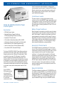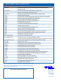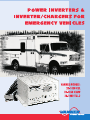
1
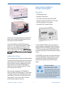
AC POWER FOR EMERGENCY VEHICLES
A set of remote options allow flexibility in configuring the
inverter system for specific needs. The optional IFM1 Interface
Module, enables the two remote status panels, system on/off
switch, and the Inverter Lockout Interlock to be connected to
the 20-1050CUL/CULW system.
12 Volt Power Inverter
The power inverter is a highly reliable electronic power
conversion unit that utilizes MOSFET power semiconductors and
a microprocessor controller. It converts 12 volt DC battery power
into 1050 watts of modified sine wave 120 volt AC power. This
AC output power is precisely regulated at 120 Volts ±5% and
60Hz ± 0.1Hz.
Model 20-1050CUL/CULW AC Power
Inverter System
Battery Charger/Conditioner
Key Features
When the system is connected to shore/utility power the battery
charger/conditioner will automatically charge the battery, then
keep it fully charged. The system's microprocessor controls the
charging sequence, starting with the Bulk charge (55 amps on
High setting, 15 amps on Low setting) mode. When the battery
is fully charged, it switches to the ready/maintenance mode to
keep the battery “topped up”. The unit is designed to charge
either lead acid flooded (wet) or gel type batteries.
• 1050 Watt Power Inverter
• Adjustable Battery Charger/Conditioner
55 Amp-High Setting/15 Amp-Low Setting
• Automatic AC Transfer Switch
• UL Certified to Federal Specification KKK-A-1822D
• Underwriters Laboratories Listed (UL and C-UL Listed)
• Remote Monitor/Control System (Requires IFM1)
• Inverter Lockout Control Interlock (Requires IFM1)
Automatic AC Transfer Switch
• Ground Fault (GFCI) Protected AC Output
The 20-1050CUL system is provided with a 2.75 ft. AC power
line cord. When connected to shore/utility power, the internal
transfer switch routes the incoming 120 volt AC power to the AC
output receptacle and to the input of the battery charger/
conditioner. In this mode, loads connected to the AC output
receptacle are supplied with shore/utility power and the battery
charger/conditioner will automatically charge and maintain
the battery. When the shore/utility power is disconnected, the
120 VAC output receptacle is switched from shore/utility power
to the power inverter. If the inverter switch is On, the power
inverter immediately (within 30 ms) supplies AC power to the
AC output receptacle.
The Vanner 20-1050CUL/CULW AC Power System combines a
powerful DC to AC power inverter with an automatic battery
charger/conditioner and a 30 amp AC transfer switch. When
connected to shore power (AC utility power) the vehicle’s
battery is charged, then automatically maintained in full
charge condition. The shore power is automatically connected
to the system’s AC output receptacle to supply power to the AC
loads. When shore power is disconnected (vehicle underway)
the automatic transfer switch connects the AC output receptacle
to the power inverter, which obtains power from the 12 volt
battery.
The 20-1050CUL/
CULW system contains
a front panel LED
indicator status panel
and interface connector
for the remote
monitor/control units.
Model 20-1050CULW
The difference between a hardwire unit (20-1050CULW) and a
non-hardwire unit (20-1050CUL) is in the 120 VAC input wiring
to the Automatic AC Transfer Switch. The actual function of the
Transfer Relay system in the 20-1050CULW is identical to the
20-1050CUL; however, on the 20-1050CULW system, the AC
input is hardwired through a wiring box located at the back
IFM1 Interface Module
VANNER POWER GROUP
-2-
Power for EMS Vehicles
Vanner Model 20-1000TUL.2
AC Power Inverter System
Key Features
• 1,050 Watt Power Inverter
• Automatic AC Transfer Switch
• UL Certified to Federal Specification KKK-A-1822D
20-1050CULW — Front View
• Underwriters Laboratories Listed (UL and C-UL Listed)
• Optional Remote Monitor/Control System
• Ground Fault (GFCI) Protected AC Output
20-1050CULW — Rear View
side of the unit. The purpose of the wiring box is to allow the
system installer to supply a 20-30 amp (instead of 15 amp)
shore power input to the 20-1050CULW.
Vanner Model 20-1000TUL.2
On both the 20-1050CUL and 20-1050CULW the battery
charger in the “Low” setting uses approximately 3.5 amps of
AC power to charge the batteries at the 15 amp rate. The
battery charger, on the “High” setting uses 12 amps of AC
TE
power to supply 55 amps of DC charging. NO
NOTE
TE:: The battery
capacity needs to be 220 amp
-hours or more when charging at
amp-hours
55 amps DC.
The Vanner Model 20-1000TUL power inverter system has
been the standard of the ambulance industry for many years.
Redesigned in 1996, the 20-1000TUL.2 contains the same DC
to AC inverter component as the 20-1050CUL/CULW and has
an automatic heavy-duty AC transfer switch without the battery
charger.
The 20-1000TUL.2 inverter works in conjunction with Vanner's
30-10 and 30-10GFI Battery Charger/Conditioners, has front
panel status LED indicators, and remote monitor/control
capabilities when used with the optional IFM1 Interface
Module.
Hardwiring the AC Input
There are situations where AC loads such as medical equipment
or quartz lights (which usually operate from the inverter power
during vehicle operation) need to operate from shore power
while the charger is operating. In situations such as this, the
system installer can use the model 20-1050CULW with a
hardwire input to set up the system to supply 20 or 30 amp
shore line power to the inverter unit.
Certified to Federal
Specification KKK-A-1822D
Vanner’s model 20-1050CUL/CULW and model
20-1000TUL.2 AC Power Systems have been
certified by Underwriter’s Laboratories (UL) to
meet the requirements of the Federal specification KKK-A-1822D. These
units are UL and C-UL Listed (UL Listed to Canadian National Standards)
to meet Power Inverter Emergency/Land Vehicle requirements.
When shore power is supplied to the 20-1050CULW, the
inverter is protected in the following ways: 1) The shore power
input passes through the unit's Transfer Relays and into two
circuit breakers; 2) One breaker is 15 amps to protect the AC
output receptacle. The other circuit breaker is 15 amps to
protect the battery charger AC input circuit.
VANNER POWER GROUP
-3-
Power for EMS Vehicles
INVERTER SYSTEM REMOTE ACCESSORIES
Remote System On/Off Switch
The 20-1050CUL/CULW and 20-1000TUL.2 AC Power Inverter
Systems support a variety of options designed to maximize the
vehicle’s electrical power capabilities. System options include a
remote shore power/charging status panel, a remote inverter
status panel, a remote system on/off switch, and the IFM1
interface module.
This switch allows the AC Power System to be remote controlled
and normally would be installed near the Remote Power
Inverter Panel. This On/Off switch controls the power inverter
only. In the
20-1050CUL/CULW system
the battery charger/
conditioner will always be
On if shore/utility power in
present. The remote switch
is provided with an eight
foot (8') cable that connects
Remote Switch Assembly—D06781
to the IFM1 Interface
Module.
IFM1 INTERFACE MODULE
Remote Power Inverter Panel
This remote panel contains
a green INVERTER LED
that shows when the
inverter is in Standby
(flashing) or On (steady). A
red FAULT LED shows a
problem such as Over
Inverter Status Panel—D06638
Temperature, Output
Overload or Low Battery. The panel has a sealed front overlay
and can be mounted on a flat surface with four screws. A 12"
wiring pigtail is provided to allow wiring to the IFM1 Interface
Module.
Interface Module
This Interface Module (Model IFM1) enables various remote
options to be connected to the 20-1050CUL/CULW, or
20-1000TUL.2 Power System. The IFM1 is supplied with a two
foot (2') data cable to connect it to the inverter system.
Electrical terminals on the IFM1 permit wiring to the two
remote status panels, remote on/off rocker switch, and to the
module disconnect switch for the inverter lockout control. The
IFM1 can be mounted conveniently near the 20-1050CUL/
CULW, or 20-1000TUL.2 unit.
Remote Charger Indicator Panel
This remote panel contains a green CHARGING LED to show
when AC shore/utility power is present, charging and maintaining the battery. A red FAULT LED shows the charger is
Off due to a problem such
as Over Temperature or
Overload. The panel has a
sealed front overlay and
can be mounted on a flat
surface with four screws.
A 12" wiring pigtail is
provided to permit wiring
Charger Indicator Panel—D06639
to the IFM1 Interface
Module.
In order to meet the Federal KKK-A-1822D ambulance
specification requirements it is necessary to add an inverter
lockout control. This control is provided by the IFM1 Interface
Module. The Inverter Lockout Control terminal on the IFM1 is
wired to the emergency vehicle's module disconnect switch load
side. This control interlock ensures that when the Module
Disconnect Switch is off, the 20-1050CUL/CULW or
20-1000TUL.2 cannot switch into the inverter mode, which
could discharge the vehicle’s battery. (See the 12 Volt Electrical
System - Functional Diagram, on page 5.)
VANNER POWER GROUP
-4-
Power for EMS Vehicles
INVERTER SYSTEM WIRING DIAGRAMS
VANNER 20-1050 AC POWER SYSTEM
VANNER 20-1000TUL.2 AC POWER SYSTEM
12 VOLT ELECTRICAL SYSTEM-FUNCTIONAL DIAGRAM FEDERAL SPECIFICATION KKK-A-1822D
VANNER POWER GROUP
-5-
Power for EMS Vehicles
Inverter Dimensions
AMBULANCE INVERTER SPECIFICATIONS
Inverter Model:
20-1050CUL/CULW
20-1000TUL.2
Output at 120 VAC Continuous
1050 Watts
1050 Watts
Surge Capacity at 120 VAC (3 sec)
2100 Watts
2100 Watts
12 VDC Nominal
12 VDC Nominal
Input Voltage, VDC
(Deep Cycle Battery Recommended) 10.5 VDC min., 16.0 VDC max. 10.5 VDC min., 16.0 VDC max.
Output Voltage
120 Volts ±5%
120 Volts ±5%
OFF
0.017 A Typical
0.017 A Typical
Load Demand (Waiting)*
0.09 A Typical
0.09 A Typical
DC Current Draw (Battery)
Full ON at No Load
0.7 A Typical
0.7 A Typical
Full ON with Load
Approx. Load Wattage ÷ 10
Approx. Load Wattage ÷ 10
or Load Amps x 12
or Load Amps x 12
60Hz ± 0.1Hz
60Hz ± 0.1Hz
Modified Sine Wave
Modified Sine Wave
Frequency
Output Waveform
Battery Charger
55 A (High)*
Charging Capacity
15 A (Low)*
N/A
Input Current
12 A
N/A
Bulk Voltage
14.2 VDC (flooded),
Float Voltage
13.2 VDC (flooded),
14.1 VDC (gel)*
N/A
13.6 VDC (gel)*
N/A
Bypass Transfer
120 VAC ± 10%
Input Voltage
Output Current, GFCI Outlet
12 Amp
Other Specifications
Ambient Temperature
Cooling Air
Chassis
Dimensions
Weight
-20 to 110° F, -29 to 43.4°C
Thermostatically controlled fan cooling
White painted aluminum with noncorrosive hardware
See dimensional diagrams
22lbs
* Setup switches are located on the front panel.
IFM1 Interface Module Dimensions
Power Inverter Remote Dimensions
VANNER POWER GROUP
-6-
Power for EMS Vehicles
OTHER VANNER EMS POWER PRODUCTS
Automatic Throttles
IQ/Bravo Series Inverters &
Inverter/Chargers
Vanner's Automatic Throttle Control System increases
engine RPM, while in park or neutral, in order to provide
higher output of the alternator under heavy electrical
loading conditions. Automatic Throttles can be used on
many types of vehicles, and are an excellent choice for
applications using DC to AC inverters.
Designed to
deliver
regulated AC
power for
sensitive and
demanding
applications
these inverters and inverter/
chargers are highly reliable UL Listed units that are easy
to install and simple to operate. The Bravo units are
available in 1800 and 2600 watts with a battery charger
option, and an optional remote panel.
When equipped with the
optional VoltGuard®
Electronic Low/Battery
Voltage Monitor, the
automatic throttle activates
when the vehicle's voltage
drops below 12.6 VDC.
IQ Series Model Numbers: IQ2600 & IQC2600
Battery Chargers
• 2600 Watts, 65 Surge Power Amps
• 120 Volts ±5%
• 12 VDC Input Battery Voltage
• 120 Amp Battery Charger (IQC models only)
• Load Demand Switch
• Automatic Circuitry Protection
• Status Indicators - Inverter On, Battery Low, Over Temp,
and Over Load
• Limited Compatibility with IFM1 Interface Module
The UL Listed ChargeMaster series of lead-acid battery
chargers provide 10 Amps of regulated DC current for
both stationary and mobile charging applications where
extended life, high
reliability, and freedom
from maintenance are
mandatory.
Built for heavy-duty
applications, these
chargers can be used with
portable generators and
produce regulated outputs even in areas having poorly
regulated AC line power.
Bravo Model Numbers: BR1800 & BRC1800
• 1800 Watts, 25 Surge Power Amps
• 120 Volts ±5%
• 12 VDC Input Battery Voltage
• 80 Amp Battery Charger (BRC models only)
• Load Demand Switch
• Automatic Circuitry Protection
• Status Indicators - Inverter On, Battery Low, Over Temp,
and Over Load
• IFM1 Compatible
Battery Isolators
Vanner Battery Isolators are designed to allow dual
battery systems to be charged from a battery charging
source while preventing one battery from discharging the
other. This protects the engine
battery from being discharged by an auxiliary
battery operation. Silicon
Diode and the low voltage
loss Schottky Diode Isolators
are available in several current
ratings.
Electronic Flashers
Vanner's heavy-duty Electronic
Flashers are designed to meet the
demanding needs of emergency
response vehicles. These flashers are
short-circuit proof, provide silent
operation, and are hermetically sealed to
protect against the elements and resist shock and
vibration.
VANNER POWER GROUP
-7-
Power for EMS Vehicles
VANNER EMERGENCY VEHICLE POWER PRODUCTS
Model/Part Number
Description
20-1050CUL
Combination Power Inverter, Battery Charger/Conditioner and Automatic AC Transfer Switch System,
with mating DC Connector
Combination Power Inverter, Battery Charger/Conditioner, Hardwired AC Input,
Automatic AC Transfer Switch System, with mating DC Connector
Combination Power Inverter and Automatic AC Transfer Switch, with mating DC Connector
Interface Module (with 2ft. data cable)
Remote System ON/OFF Switch Assembly (Rocker Switch with 8ft. Cable, used with IFM1 Interface Module)
Remote Power Inverter Indicator Panel, used with IFM1 Interface Module
Remote Charge Indicator Panel, used with IFM1 Interface Module
Remote Switch Adapter (For Older Model Rocker Switch Assemblies)
DC Cable Adapter (Blue to Gray Connector)
Rocker Switch for model D06781 Remote ON/OFF Switch Assembly
Fuse Holder (For Bussmann ANN-125)
Fuse 125A for 1000 watt & 1050 watt inverters (Bussmann Ann-125)
Fuse 200A for 1800 watt inverters (Bussmann ANN-200)
Fuse 400A for 2600 watt inverters (Bussmann ANN-400)
Gray DC Connector w/Contacts (supplied with 20-1050CUL, 20-1050CULW, and 20-1000TUL.2)
DC Connector Strain Relief (supplied with 20-1050CUL, 20-1050CULW, and 20-1000TUL.2)
Reducer Bushing to #2 AWG (need 2 per connector)
Bravo 1800 Power Inverter, Hardwire (IQ1800*)
Bravo 1800 Power Inverter, GFCI Protected Duplex Receptacle (IQ1800*)
* IQ12-1800 model will eventually replace Bravo 1800 units and will include both a Hardwire and GFCI Receptacle)
Bravo 1800 (IQC1800) Combination Power Inverter, Battery Charger/Conditioner, Hardwire
IQ2600 Power Inverter, Hardwire
IQ2600 Combination Power Inverter, Battery Charger/Conditioner, Hardwire
Bravo Remote Panel (Switch and 3 LEDs) w/20' Cable, used with Bravo 1800
Warning Light Flasher, Alternating, Dual 50 Amp Outputs
Warning Light Flasher, Alternating, Dual 12 Amp Outputs
Warning Light Flasher, Duo-mode for KKK-B Vehicles, 30/30/30 Amp
Warning Light Flasher, Duo-mode for KKK-C & D Vehicles, 40/24/30 Amp
Heavy-duty Automatic Throttle System with solenoid/cable assembly, and control module assembly
Auto Throttle kit with ON/OFF toggle switch, #02264 isolation diode, fuse, and fuse holder
Volt Guard low voltage auto throttle actuator
Battery Charger/Conditioner, 12 VDC, 10 Amp, w/AC Outlet
Battery Charger/Conditioner 12 VDC, 10 Amp, w/GFCI AC Outlet
Silicon Battery Isolator, 2 Battery, 180 Amp Alternator
Schottky Battery Isolator, 2 Battery, 250 Amp Alternator
Schottky Medical Isolator, 75 Amp Surge
20-1050CULW
20-1000TUL.2
IFM1
D06781
D06638
D06639
D06625
D06623
02635
03637
03640
04522
04523
02216
02218
02217
BR12-1800SH/IQ12-1800
BR12-1800SG/IQ12-1800
BRC12-1800SH/IQC12-1800
IQ12-2600
IQC12-2600
D05039
1250GCP
1616GCP
1840GCP
1860GCP
73-46
73-48
70-VG
30-10
30-10GFI
50-140
51-140
52-75
To the best or our knowledge the statements, specifications, and instructions in this document are correct. No warranty is made,
expressed, or implied by the seller or manufacturer with respect to any results or lack thereof from the use of information in this
document ad no liability is assumed for any direct or indirect damages, personal loss, or injury. All statements made within this
document are to be applied or relied upon at the user's risk.
Vanner Power Products Distributed By:
4282 Reynolds Drive
Hilliard, Ohio 43026
TEL: 614-771-2718
FAX: 614-771-4904
800-AC POWER
www.vanner.com
EMSBRCH/0798 Printed in the U.S.A. Specifications subject to change without notice
©Copyright 1998, Vanner Inc.