1
For Parts Call 606-678-9623 or 606-561-4983
Professional Shop Manual
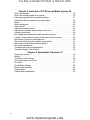
700 Series Riding Tractors
NOTE: These materials are for use by trained technicians who are experienced in the service and repair of outdoor power
equipment of the kind described in this publication, and are not intended for use by untrained or inexperienced individuals.
These materials are intended to provide supplemental information to assist the trained technician. Untrained or inexperienced individuals should seek the assistance of an experienced and trained professional. Read, understand, and follow all
instructions and use common sense when working on power equipment. This includes the contents of the product’s Operators Manual, supplied with the equipment. No liability can be accepted for any inaccuracies or omission in this publication,
although care has been taken to make it as complete and accurate as possible at the time of publication. However, due to
the variety of outdoor power equipment and continuing product changes that occur over time, updates will be made to these
instructions from time to time. Therefore, it may be necessary to obtain the latest materials before servicing or repairing a
product. The company reserves the right to make changes at any time to this publication without prior notice and without
incurring an obligation to make such changes to previously published versions. Instructions, photographs and illustrations
used in this publication are for reference use only and may not depict actual model and component parts.
© Copyright 2010 MTD Products Inc. All Rights Reserved
MTD Products Inc. - Product Training and Education Department
4
FORM NUMBER - 769-06667
11/2010
www.mymowerparts.com
For Parts Call 606-678-9623 or 606-561-4983
www.mymowerparts.com
For Parts Call 606-678-9623 or 606-561-4983
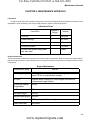
Table of Contents
Chapter 1: Introduction 1
Professional Shop manual intent . . . . . . . . . . . . . . . . . . . . . . . . . . . . . . . . . . 1
Fasteners . . . . . . . . . . . . . . . . . . . . . . . . . . . . . . . . . . . . . . . . . . . . . . . . . . . . 1
Assembly . . . . . . . . . . . . . . . . . . . . . . . . . . . . . . . . . . . . . . . . . . . . . . . . . . . . 2
Description of the 700 series . . . . . . . . . . . . . . . . . . . . . . . . . . . . . . . . . . . . . 2
Model and Serial Numbers . . . . . . . . . . . . . . . . . . . . . . . . . . . . . . . . . . . . . . . 3
Chapter 2: Engine Related Parts 5
Muffler . . . . . . . . . . . . . . . . . . . . . . . . . . . . . . . . . . . . . . . . . . . . . . . . . . . . . . 5
Fuel tank removal/replacement . . . . . . . . . . . . . . . . . . . . . . . . . . . . . . . . . . . 6
Chapter 3: Steering and Front Axle 9
Front wheel removal and axle bearing inspection . . . . . . . . . . . . . . . . . . . . 10
Left Front Axle Removal . . . . . . . . . . . . . . . . . . . . . . . . . . . . . . . . . . . . . . . . 10
Right Front Axle Removal . . . . . . . . . . . . . . . . . . . . . . . . . . . . . . . . . . . . . . . 11
General Information . . . . . . . . . . . . . . . . . . . . . . . . . . . . . . . . . . . . . . . . . . . 11
Pivot Bar . . . . . . . . . . . . . . . . . . . . . . . . . . . . . . . . . . . . . . . . . . . . . . . . . . . . 11
Installation notes . . . . . . . . . . . . . . . . . . . . . . . . . . . . . . . . . . . . . . . . . . . . . . 13
Steering Gear Inspection . . . . . . . . . . . . . . . . . . . . . . . . . . . . . . . . . . . . . . . 14
Steering Shaft Replacement . . . . . . . . . . . . . . . . . . . . . . . . . . . . . . . . . . . . . 15
Steering Gear Replacement . . . . . . . . . . . . . . . . . . . . . . . . . . . . . . . . . . . . . 16
Steering Link Rod Replacement . . . . . . . . . . . . . . . . . . . . . . . . . . . . . . . . . . 18
Front wheel alignment . . . . . . . . . . . . . . . . . . . . . . . . . . . . . . . . . . . . . . . . . 20
Chapter 4: Body Panels 23
What is covered by this chapter . . . . . . . . . . . . . . . . . . . . . . . . . . . . . . . . . 23
Hood Removal. . . . . . . . . . . . . . . . . . . . . . . . . . . . . . . . . . . . . . . . . . . . . . . 23
Hood components . . . . . . . . . . . . . . . . . . . . . . . . . . . . . . . . . . . . . . . . . . . . 25
Seat and Fenders . . . . . . . . . . . . . . . . . . . . . . . . . . . . . . . . . . . . . . . . . . . . 25
Seat Removal . . . . . . . . . . . . . . . . . . . . . . . . . . . . . . . . . . . . . . . . . . . . . . . . 26
Seat bracket removal . . . . . . . . . . . . . . . . . . . . . . . . . . . . . . . . . . . . . . . . . . 27
Fender Removal . . . . . . . . . . . . . . . . . . . . . . . . . . . . . . . . . . . . . . . . . . . . . . 28
Dash Panel . . . . . . . . . . . . . . . . . . . . . . . . . . . . . . . . . . . . . . . . . . . . . . . . . 31
To remove the lower dash . . . . . . . . . . . . . . . . . . . . . . . . . . . . . . . . . . . . . 32
I
www.mymowerparts.com
For Parts Call 606-678-9623 or 606-561-4983
Chapter 5: Auto-drive CVT Drive and Brake System 35
About this chapter . . . . . . . . . . . . . . . . . . . . . . . . . . . . . . . . . . . . . . . . . . . . . 35
About the variable speed drive system . . . . . . . . . . . . . . . . . . . . . . . . . . . . . 36
Externally repairable drive system problems: . . . . . . . . . . . . . . . . . . . . . . . . 37
Indications that a transaxle is not warrantable . . . . . . . . . . . . . . . . . . . . . . . 39
Brake . . . . . . . . . . . . . . . . . . . . . . . . . . . . . . . . . . . . . . . . . . . . . . . . . . . . . . 39
Brake adjustment . . . . . . . . . . . . . . . . . . . . . . . . . . . . . . . . . . . . . . . . . . . . . 40
Gear selector . . . . . . . . . . . . . . . . . . . . . . . . . . . . . . . . . . . . . . . . . . . . . . . . 41
Adjusting Gearshift Lever . . . . . . . . . . . . . . . . . . . . . . . . . . . . . . . . . . . . . . . 42
Adjusting the variable speed pulley control rod . . . . . . . . . . . . . . . . . . . . . . 43
Linkage: pedal shaft . . . . . . . . . . . . . . . . . . . . . . . . . . . . . . . . . . . . . . . . . . . 45
Drive pedal and brake pedal shaft assembly removal. . . . . . . . . . . . . . . . . 46
Linkage: Cobra head to control rod tie plate and hex bushing . . . . . . . . . . . 49
Belt control: Upper drive belt idler arm . . . . . . . . . . . . . . . . . . . . . . . . . . . . . 50
Belt control: Servicing the variable speed pulley . . . . . . . . . . . . . . . . . . . . . 51
Belt control: Double idler tensioner pulleys . . . . . . . . . . . . . . . . . . . . . . . . . 53
Drive belt replacement . . . . . . . . . . . . . . . . . . . . . . . . . . . . . . . . . . . . . . . . . 57
Transaxle removal and replacement . . . . . . . . . . . . . . . . . . . . . . . . . . . . . . 60
Transaxle Repair - Bench Work . . . . . . . . . . . . . . . . . . . . . . . . . . . . . . . . . . 62
Chapter 6: Hydrostatic Transaxle 75
Purging the system . . . . . . . . . . . . . . . . . . . . . . . . . . . . . . . . . . . . . . . . . . . . 76
Brakes . . . . . . . . . . . . . . . . . . . . . . . . . . . . . . . . . . . . . . . . . . . . . . . . . . . . . 77
Transaxle control linkage . . . . . . . . . . . . . . . . . . . . . . . . . . . . . . . . . . . . . . . 78
Cross-shaft and control lever . . . . . . . . . . . . . . . . . . . . . . . . . . . . . . . . . . . . 79
Drive Belt . . . . . . . . . . . . . . . . . . . . . . . . . . . . . . . . . . . . . . . . . . . . . . . . . . . 81
Clutch/Brake linkage . . . . . . . . . . . . . . . . . . . . . . . . . . . . . . . . . . . . . . . . . . 83
Brake pedal assembly . . . . . . . . . . . . . . . . . . . . . . . . . . . . . . . . . . . . . . . . . 85
Parking brake . . . . . . . . . . . . . . . . . . . . . . . . . . . . . . . . . . . . . . . . . . . . . . . . 86
Parking brake adjustment . . . . . . . . . . . . . . . . . . . . . . . . . . . . . . . . . . . . . . . 87
II
www.mymowerparts.com
For Parts Call 606-678-9623 or 606-561-4983
Chapter 7: Electrical System 89
Introduction . . . . . . . . . . . . . . . . . . . . . . . . . . . . . . . . . . . . . . . . . . . . . . . . . . 89
OCR Module . . . . . . . . . . . . . . . . . . . . . . . . . . . . . . . . . . . . . . . . . . . . . . . . . 90
Key switch . . . . . . . . . . . . . . . . . . . . . . . . . . . . . . . . . . . . . . . . . . . . . . . . . . 91
OCR Module . . . . . . . . . . . . . . . . . . . . . . . . . . . . . . . . . . . . . . . . . . . . . . . . . 94
Identifying a faulty OCR module . . . . . . . . . . . . . . . . . . . . . . . . . . . . . . . . . . 95
PTO switch . . . . . . . . . . . . . . . . . . . . . . . . . . . . . . . . . . . . . . . . . . . . . . . . . . 98
Brake switch . . . . . . . . . . . . . . . . . . . . . . . . . . . . . . . . . . . . . . . . . . . . . . . . 98
Park Brake Switch . . . . . . . . . . . . . . . . . . . . . . . . . . . . . . . . . . . . . . . . . . . . 99
Reverse Safety Switch . . . . . . . . . . . . . . . . . . . . . . . . . . . . . . . . . . . . . . . . 100
Seat Safety Switch . . . . . . . . . . . . . . . . . . . . . . . . . . . . . . . . . . . . . . . . . . 101
Starter solenoid . . . . . . . . . . . . . . . . . . . . . . . . . . . . . . . . . . . . . . . . . . . . . 102
Lighting circuit . . . . . . . . . . . . . . . . . . . . . . . . . . . . . . . . . . . . . . . . . . . . . . . 103
Start Circuit . . . . . . . . . . . . . . . . . . . . . . . . . . . . . . . . . . . . . . . . . . . . . . . . . 104
Run Circuit . . . . . . . . . . . . . . . . . . . . . . . . . . . . . . . . . . . . . . . . . . . . . . . . 106
Run Circuit / Reverse Caution mode . . . . . . . . . . . . . . . . . . . . . . . . . . . . . 108
Safety circuits . . . . . . . . . . . . . . . . . . . . . . . . . . . . . . . . . . . . . . . . . . . . . . . 109
Charging circuit . . . . . . . . . . . . . . . . . . . . . . . . . . . . . . . . . . . . . . . . . . . . . . 111
Testing the charging system . . . . . . . . . . . . . . . . . . . . . . . . . . . . . . . . . . . . 114
Electrical diagnosis . . . . . . . . . . . . . . . . . . . . . . . . . . . . . . . . . . . . . . . . . . . 119
Electronics . . . . . . . . . . . . . . . . . . . . . . . . . . . . . . . . . . . . . . . . . . . . . . . . . 119
Electrical environment: AC Vs. DC . . . . . . . . . . . . . . . . . . . . . . . . . . . . . . . 120
Ohm’s Law . . . . . . . . . . . . . . . . . . . . . . . . . . . . . . . . . . . . . . . . . . . . . . . . . 121
Kirchhoff’s current law . . . . . . . . . . . . . . . . . . . . . . . . . . . . . . . . . . . . . . . . 121
Kirchhoff’s voltage law . . . . . . . . . . . . . . . . . . . . . . . . . . . . . . . . . . . . . . . . 122
How the system is wired together . . . . . . . . . . . . . . . . . . . . . . . . . . . . . . . . 122
Types of circuits . . . . . . . . . . . . . . . . . . . . . . . . . . . . . . . . . . . . . . . . . . . . . 123
Series . . . . . . . . . . . . . . . . . . . . . . . . . . . . . . . . . . . . . . . . . . . . . . . . . . . . . 123
Parallel . . . . . . . . . . . . . . . . . . . . . . . . . . . . . . . . . . . . . . . . . . . . . . . . . . . . 123
Series/parallel . . . . . . . . . . . . . . . . . . . . . . . . . . . . . . . . . . . . . . . . . . . . . . . 124
Shorts . . . . . . . . . . . . . . . . . . . . . . . . . . . . . . . . . . . . . . . . . . . . . . . . . . . . . 124
Opens . . . . . . . . . . . . . . . . . . . . . . . . . . . . . . . . . . . . . . . . . . . . . . . . . . . . 124
Increased resistance . . . . . . . . . . . . . . . . . . . . . . . . . . . . . . . . . . . . . . . . . 124
The Tools . . . . . . . . . . . . . . . . . . . . . . . . . . . . . . . . . . . . . . . . . . . . . . . . . . 125
Digital Multi-meter . . . . . . . . . . . . . . . . . . . . . . . . . . . . . . . . . . . . . . . . . . . . 126
Wiring diagram or schematic . . . . . . . . . . . . . . . . . . . . . . . . . . . . . . . . . . . 127
Fused jumper wires . . . . . . . . . . . . . . . . . . . . . . . . . . . . . . . . . . . . . . . . . . 127
Test lights . . . . . . . . . . . . . . . . . . . . . . . . . . . . . . . . . . . . . . . . . . . . . . . . . . 127
Self-powered continuity lights . . . . . . . . . . . . . . . . . . . . . . . . . . . . . . . . . . . 127
Ammeters and specialized charging system testers . . . . . . . . . . . . . . . . . 128
Batteries . . . . . . . . . . . . . . . . . . . . . . . . . . . . . . . . . . . . . . . . . . . . . . . . . . 129
Charging the battery . . . . . . . . . . . . . . . . . . . . . . . . . . . . . . . . . . . . . . . . . . 129
Checking battery condition . . . . . . . . . . . . . . . . . . . . . . . . . . . . . . . . . . . . . 130
Battery Testers . . . . . . . . . . . . . . . . . . . . . . . . . . . . . . . . . . . . . . . . . . . . . . 131
Adjustable load testers . . . . . . . . . . . . . . . . . . . . . . . . . . . . . . . . . . . . . . . . 131
Fixed load testers . . . . . . . . . . . . . . . . . . . . . . . . . . . . . . . . . . . . . . . . . . . 132
III
www.mymowerparts.com
For Parts Call 606-678-9623 or 606-561-4983
Conductance testers . . . . . . . . . . . . . . . . . . . . . . . . . . . . . . . . . . . . . . . . . 132
Battery discharge test . . . . . . . . . . . . . . . . . . . . . . . . . . . . . . . . . . . . . . . . 133
Storage of batteries . . . . . . . . . . . . . . . . . . . . . . . . . . . . . . . . . . . . . . . . . . 133
Electrical Troubleshooting . . . . . . . . . . . . . . . . . . . . . . . . . . . . . . . . . . . . . 134
Voltage Drop Test . . . . . . . . . . . . . . . . . . . . . . . . . . . . . . . . . . . . . . . . . . . . 136
Testing switches . . . . . . . . . . . . . . . . . . . . . . . . . . . . . . . . . . . . . . . . . . . . . 139
Diodes . . . . . . . . . . . . . . . . . . . . . . . . . . . . . . . . . . . . . . . . . . . . . . . . . . . . 140
Schematic . . . . . . . . . . . . . . . . . . . . . . . . . . . . . . . . . . . . . . . . . . . . . . . . . . 142
Chapter 8: Cutting Decks 149
Cutting decks . . . . . . . . . . . . . . . . . . . . . . . . . . . . . . . . . . . . . . . . . . . . . . . 149
Deck Wash Features . . . . . . . . . . . . . . . . . . . . . . . . . . . . . . . . . . . . . . . . . 149
Deck removal . . . . . . . . . . . . . . . . . . . . . . . . . . . . . . . . . . . . . . . . . . . . . . . 150
Cleaning the Deck . . . . . . . . . . . . . . . . . . . . . . . . . . . . . . . . . . . . . . . . . . . 152
To clean the deck while it is removed . . . . . . . . . . . . . . . . . . . . . . . . . . . . 152
Cutting Blades . . . . . . . . . . . . . . . . . . . . . . . . . . . . . . . . . . . . . . . . . . . . . . 152
Blade Removal . . . . . . . . . . . . . . . . . . . . . . . . . . . . . . . . . . . . . . . . . . . . . . 153
PTO Belt . . . . . . . . . . . . . . . . . . . . . . . . . . . . . . . . . . . . . . . . . . . . . . . . . . . 154
To replace the PTO belt . . . . . . . . . . . . . . . . . . . . . . . . . . . . . . . . . . . . . . . 155
Deck with a Timing Belt . . . . . . . . . . . . . . . . . . . . . . . . . . . . . . . . . . . . . . . 158
Pulleys and Spindles . . . . . . . . . . . . . . . . . . . . . . . . . . . . . . . . . . . . . . . . . 160
Blade Brake System . . . . . . . . . . . . . . . . . . . . . . . . . . . . . . . . . . . . . . . . . . 162
Leveling the deck . . . . . . . . . . . . . . . . . . . . . . . . . . . . . . . . . . . . . . . . . . . . 164
Side to Side Leveling . . . . . . . . . . . . . . . . . . . . . . . . . . . . . . . . . . . . . . . . . 164
Front To Rear Leveling . . . . . . . . . . . . . . . . . . . . . . . . . . . . . . . . . . . . . . . . 165
Deck Wheel Adjustment . . . . . . . . . . . . . . . . . . . . . . . . . . . . . . . . . . . . . . . 166
Deck lift shaft assembly bushings . . . . . . . . . . . . . . . . . . . . . . . . . . . . . . . 167
Deck lift shaft assembly removal/replacement . . . . . . . . . . . . . . . . . . . . . 167
Deck lift links . . . . . . . . . . . . . . . . . . . . . . . . . . . . . . . . . . . . . . . . . . . . . . . . 169
Manual PTO Blade Engagement Lever . . . . . . . . . . . . . . . . . . . . . . . . . . . 169
Cutting Deck Engagement Lever Replacement . . . . . . . . . . . . . . . . . . . . 170
Replacing the cutting deck engagement cable . . . . . . . . . . . . . . . . . . . . . . 171
Chapter 9: Maintenance Intervals 173
Lubrication . . . . . . . . . . . . . . . . . . . . . . . . . . . . . . . . . . . . . . . . . . . . . . . . . 173
Engine maintenance . . . . . . . . . . . . . . . . . . . . . . . . . . . . . . . . . . . . . . . . . . 173
General maintenance tips . . . . . . . . . . . . . . . . . . . . . . . . . . . . . . . . . . . . . . 174
The spark plug(s) . . . . . . . . . . . . . . . . . . . . . . . . . . . . . . . . . . . . . . . . . . . . 174
Air filter and foam pre cleaner . . . . . . . . . . . . . . . . . . . . . . . . . . . . . . . . . . 175
Oil change . . . . . . . . . . . . . . . . . . . . . . . . . . . . . . . . . . . . . . . . . . . . . . . . . 176
Oil filter . . . . . . . . . . . . . . . . . . . . . . . . . . . . . . . . . . . . . . . . . . . . . . . . . . . . 177
Fuel system . . . . . . . . . . . . . . . . . . . . . . . . . . . . . . . . . . . . . . . . . . . . . . . . 178
Servicing the fuel system . . . . . . . . . . . . . . . . . . . . . . . . . . . . . . . . . . . . . . 178
Fuel filter . . . . . . . . . . . . . . . . . . . . . . . . . . . . . . . . . . . . . . . . . . . . . . . . . . . 178
Clean the engine . . . . . . . . . . . . . . . . . . . . . . . . . . . . . . . . . . . . . . . . . . . . 179
Lubricate the pedal shaft . . . . . . . . . . . . . . . . . . . . . . . . . . . . . . . . . . . . . . 179
IV
www.mymowerparts.com
For Parts Call 606-678-9623 or 606-561-4983
Introduction
CHAPTER 1: INTRODUCTION
Professional Shop manual intent
This Shop Manual is intended to provide service dealers with an introduction to the mechanical aspects of the 700
series tractor.
•
Detailed service information about the engine will be provided by the engine manufacturer, in most cases.
Disclaimer: The information contained in this shop manual is correct at the time of writing. Both the product and the
information about the product are subject to change without notice.
About the text format:
NOTE: is used to point-out information that is relevant to the procedure, but does not fit as a step in the procedure.
! DANGER
Danger indicates an imminently hazardous situation that, if not avoided, will result in death or
serious injury. This signal word is to be limited to the most extreme situations
! WARNING
Warning indicates a potentially hazardous situation that, if not avoided, could result in death of
serious injury.
! CAUTION
Caution is used to point out potential danger to the technician, operator, bystanders, or surrounding property.
Bullet points: indicate sub-steps or points.
Disclaimer: This Professional Shop Manual is intended for use by trained, professional technicians.
•
Common sense in operation and safety is assumed.
•
In no event shall MTD or Cub Cadet be liable for poor text interpretation, or poor execution of the procedures described in the text.
•
If the person using this manual is uncomfortable with any procedures they encounter, they should seek
the help of a qualified technician or Cub Cadet Technical Support.
Fasteners
•
Most of the fasteners used on the tractor are sized in fractional inches. Some are metric. For this reason,
wrench sizes are frequently identified in the text, and measurements are given in U.S. and metric scales.
•
If a fastener has a locking feature that has worn, replace the fastener or apply a small amount of releasable threadlocking compound such as Loctite® 242 (blue).
•
Some fasteners like cotter pins are single-use items that are not to be reused. Other fasteners such as
lock washers, retaining rings, and internal cotter pins (hairpin clips) may be reused if they do not show
signs of wear or damage. This manual leaves that decision to the judgement of the technician.
1
www.mymowerparts.com
For Parts Call 606-678-9623 or 606-561-4983
700 Series Lawn Tractor
Assembly
Torque specifications may be noted in the part of the text that covers assembly, they may also be summarized in
tables along with special instructions regarding locking or lubrication. Whichever method is more appropriate will be
used. In many cases, both will be used so that the manual is handy as a quick-reference guide as well as a step-bystep procedure guide that does not require the user to hunt for information.
The level of assembly instructions provided will be determined by the complexity and of reassembly, and by the
potential for unsafe conditions to arise from mistakes made in assembly.
Some instructions may refer to other parts of the manual for subsidiary procedures. This avoids repeating the same
procedure two or three times in the manual.
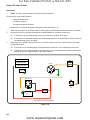
Description of the 700 series
1.
Description: A new step-through rider platform was introduced for the ‘05 mowing season. It was designated
as the 700 series rider. It is seen across many of the MTD brands and private labels. There are also several
hood configurations.The serial number and date codes are the keys to obtaining proper parts and service
information. Since that date, several drive systems have been used on this series.
2.
Variations: Drive Systems The 700 series is currently available with three basic drive systems. The 700
refers to the 5th through 7th characters of the model number found under the seat.
•
13AN772G000 is a “770” series - 7 speed shift-on-the-go transmission
NOTE: There is also a 760 series with a 6 speed shift-on-the-go transmission
•
13WX78KS011 is a “780” series - autodrive variable speed CVT tractor
•
13AR791G790 is a “790” series - Hydrostatic drive tractor
The 760-770 series is a shift-on-the-go system that uses a simple forward/neutral/reverse transaxle driven by
two belts in a variable speed pulley. A dash mounted speed range control (sets speed of rider). A foot operated brake
on the left side of the rider engages the drive when it is released.
The 780 series uses a Autodrive system with the same transmission as the 770 series. The 780, like the 770, has
the brake pedal on the left side of the tractor. A drive pedal on the right side of the tractor controls a variable-speed
pulley (CVT) system that controls the ground speed of the tractor.
The 790 series uses a hydrostatic transaxle. A pedal on the left side of the tractor operates the brake/clutch
pedal while the ground speed and direction of the tractor is controlled by a fender mounted hand control lever.
2
www.mymowerparts.com
For Parts Call 606-678-9623 or 606-561-4983
Introduction
3.
Variations: Cutting Decks Three decks sizes are currently available on the 700 series platform: 38”, 42” and
46” with twin blades. Within the different deck sizes you may find different configurations of belt routing, blade
brakes, Idlers, spindles and blades. The eighth letter in the serial number indicates the deck used on the rider.
Refer to the correct illustrated parts list when working on the deck and ordering parts.
4.
Variations: Other The 700 series platform will accommodate a variety of single and twin cylinder engines, and
a range of styles and brands will be applied to it. The steel dash panel is common to all 700 series, and plastic inserts will be used to match the different hoods used.
5.
Spotter’s Guide: The 700 series is visibly similar to the existing step-through platform 600 and 610 series
lawn tractors, but there are substantial differences.
•
Deck Engagement: The PTO belt is engaged on the 700 series using a lever on the right fender.
Model and Serial Numbers
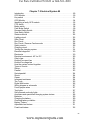
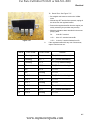
The model and serial number tag can be found under the seat.
Model number
Serial number
The serial number is located to the right of the model number as shown above.
The model number is 13AN772G000 The break down of
what the number mean is as follows:
13.........................lawn tractor
...A.......................sales level
......N.....................engine code
........7...................tractor series
..........7................drive system
............2..............hood style
...............G...........deck
...................000....customer number
The serial number is 1C259B40136. The serial number reads as follows:
1...........................engineering level
..C.........................month of production (C = March)
.....25....................day of the month
.........9..................last digit of the year
...........B................plant it was built in
..............4.............assembly line number
.................0136.....number of unit built
3
www.mymowerparts.com
For Parts Call 606-678-9623 or 606-561-4983
700 Series Lawn Tractor
4
www.mymowerparts.com
For Parts Call 606-678-9623 or 606-561-4983
Engine Related Parts
CHAPTER 2: ENGINE RELATED PARTS
This manual will cover the engine accessories that are manufactured by MTD Products.
IMPORTANT: Refer to the engine manufacturer’s manual for engine specific service information.
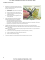
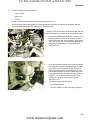
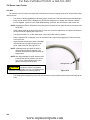
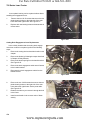
Muffler
The engine style on the rider will determine the steps needed to replace the muffler. Refer to the parts manual that
came with the rider for an illustration of the parts on the rider you are servicing.
Remove the muffler by following these steps:
NOTE: The muffler and the exhaust pipes are welded together. They are replaced as one assembly.
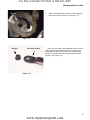
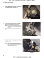
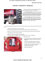
1.
Remove the hood and bumper by following the steps
described in Chapter 4: Body/Chassis.
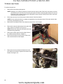
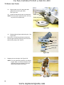
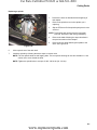
2.
Remove the two screws on each side of the frame
that secure the muffler guard to the hood support
bracket. See Figure 2.1.
3.
Remove the muffler guard.
Hood support bracket
Muffler guard
NOTE: These steps may vary slightly depending upon the
type of engine on the rider.
Screws attaching muffler guard
Figure 2.1
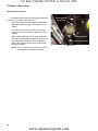
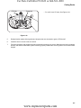
Muffler flange screws
Disconnect the muffler from the engine.
For single cylinder engines:
1.
Remove the two screws that secure the exhaust pipe
to the cylinder head. See Figure 2.2.
2.
Remove the screw that fastens the muffler support
bracket to the cylinder head. See Figure 2.2.
Muffler support screw
Figure 2.2
5
www.mymowerparts.com
For Parts Call 606-678-9623 or 606-561-4983
700 Series Lawn Tractor
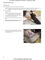
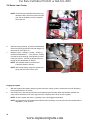
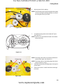
For twin cylinder engines:
1.
Remove the two nuts that secure each exhaust pipe
to the cylinder head. See Figure 2.3.
2.
Remove the muffler from the engine.
3.
Install the muffler by following the above steps in
reverse order.
4.
Install the muffler guard and hood.
5.
Test run the tractor before returning to service.
Remove these
nuts
Figure 2.3
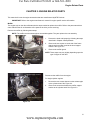
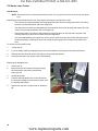
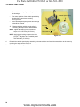
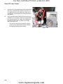
Fuel tank removal/replacement
Remove/replace the fuel tank by following these steps:
! CAUTION
The following steps involve working with gasoline. Gasoline is flammable, and steps should
be taken to avoid fire hazard;.
•
Work in a well-ventilated area.
•
Allow the engine to cool fully before starting work on the tractor.
•
Eliminate any sources of possible ignition from the work area, including but not limited to:
open flame, potential sparks.
•
Clean-up any spilled fuel quickly and properly, disposing of cleaning materials in a way that will not produce a further fire hazard.
•
Hold any drained fuel in an approved and safe container.
heat sources,
1.
Open the hood.
2.
Drain the fuel in the fuel tank into an approved container or clamp the fuel line. The steps below demonstrate
removal by clamping off the fuel line.
NOTE: The tank may be drained by mechanical syphon or by disconnecting the fuel line from the fuel filter.
6
www.mymowerparts.com
For Parts Call 606-678-9623 or 606-561-4983
Engine Related Parts
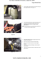
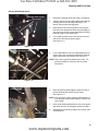
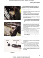
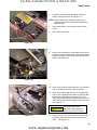
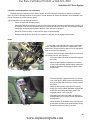
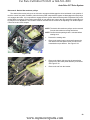
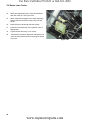
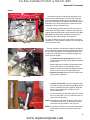
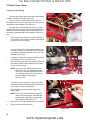
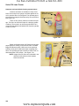
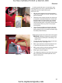
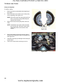
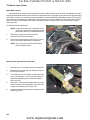
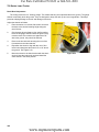
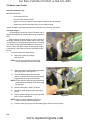
3.
Cut the plastic tie that secures the fuel tank to the gas
tank support bracket. See Figure 2.4.
4.
If you did not drain the fuel, raise the fuel tank up off
the support bracket high enough to allow you to
clamp the fuel line above the support bracket.
See Figure 2.5.
Fuel tank plastic tie
Figure 2.4
Hair pin clip
Deck lift cable
NOTE: This will allow you to remove the tank and fuel line
up and out of the support bracket.
Fuel line clamped above support bracket
Figure 2.5
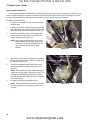
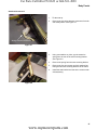
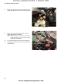
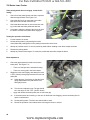
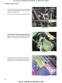
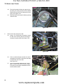
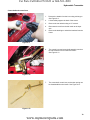
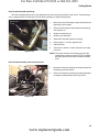
Fuel filter
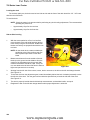
5.
Using pliers slide the fuel line clamp away from the
fuel filter. See Figure 2.6.
6.
Remove the fuel line from the fuel filter nipple.
7.
Remove the fuel tank and line from the support
bracket.
8.
Install the fuel tank by following the above steps in
reverse order.
9.
Test run the tractor and check for leaks before returning to service.
Fuel line clamp moved away from filter
Figure 2.6
7
www.mymowerparts.com
For Parts Call 606-678-9623 or 606-561-4983
700 Series Lawn Tractor
8
www.mymowerparts.com
For Parts Call 606-678-9623 or 606-561-4983
Steering and Front Axle
CHAPTER 3: STEERING AND FRONT AXLE
STEERING
This section will cover:
•
Inspection of steering components
•
Changing the front wheel bearings
•
Inspecting and removing the axles
•
Replacing a stamped steel pivot bar
•
Replacing a cast iron pivot bar
•
Replacing the steering shaft and steering gear
•
Replacing a damaged steering link
•
Front end alignment
GENERAL INFORMATION
The toe angle is not adjustable. The front wheels are kept pointed in the same direction (except for the Ackerman
effect) by a tie-rod with fixed ends. There is an adjustable end on the steering link that connects the steering gear to
the steering arm on the right front axle.
NOTE: The front wheels should exhibit 1/16” to 5/16” (1.6mm - 7.9mm) toe-in.
If the tie-rod is visibly bent, its effective length is shortened, and toe-out will result. Very minor bends may be
straightened. Substantial bends should be repaired by replacing the tie-rod.
A toe-angle problem may also be caused by worn axle bushings or worn wheel bearings: inspect the wheel bearings and axle bushings.
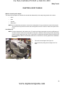
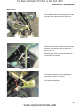
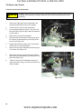
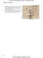
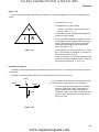
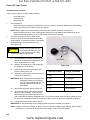
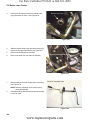
The wheel bearings may be easily examined for play:
Steering Arm
Spacer
1.
Safely lift and support the end of the pivot bar that the
wheel is attached to. See Figure 3.1.
2.
Attempt to wiggle the wheel on a horizontal axis.
• Excessive play indicates worn wheel bearings.
Rocking play (as distinguished from just slipping in
and out on the axle) that exceeds the range of
acceptable toe angle adjustment (5/16” - 1/16” = 1/
4”) is considered excessive.
Pivot Bar
Bearing
Axle
Figure 3.1
9
www.mymowerparts.com
For Parts Call 606-678-9623 or 606-561-4983
700 Series Lawn Tractor
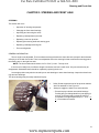
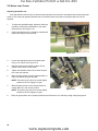
Front wheel removal and axle bearing inspection
The wheel bearings are accessible by prying-off the
hub-cap, then removing the cotter pin and flat washer that
retain the front tires. See Figure 3.2.
1.
Raise the tractor and support it with a jack stand
2.
Pry the hubcap from the axle.
3.
Remove the cotter pin that holds the wheel to the
axle.
4.
Remove the washer.
5.
Slide the wheel off the axle.
Cotter Pin
Flat Washer
Figure 3.2
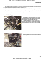
6.
The wheel bearing can be driven out of the rim.
See Figure 3.3.
7.
Replace the bearing and install the wheel in the
reverse order of disassembly.
NOTE: On installation, using a new cotter pin, the
pin must be bent tightly around the axle so
that it does not interfere with hub-cap installation.
Wheel Bearing
Grease Fitting
Figure 3.3
Left Front Axle Removal
1.
Raise the tractor and support it with a jack stand.
2.
Remove the wheel and tire as described above.
3.
Remove the cotter pin that holds the fixed tie rod to
the axle. See Figure 3.4.
4.
Axle Cap
Pry off the cap that holds the axle to the pivot par.
Discard the cap and replace it with a new one during
assembly.
Cotter Pin
NOTE: This cap holds the left axle in place.
Removing the axle allows access to the upper and
lower flange bearing and side axle cap. Inspect these
components for wear or damage and replace if necessary.
Assemble in reverse order of disassembly.
Figure 3.4
10
www.mymowerparts.com
For Parts Call 606-678-9623 or 606-561-4983
Steering and Front Axle
Right Front Axle Removal
Steering Arm
Clamp Bolt
Spacer
1.
Raise the tractor and support it with a jack stand.
2.
Remove the wheel and tire as described above.
3.
Remove the cotter pin that fastens the fixed tie rod to
the axle. See Figure 3.5.
4.
Loosen the clamp bolt that secures the steering arm
to the square-section at the top of the axle using a
pair of 1/2” wrenches, and lifting the arm off.
NOTE: Note the spacer below the steering arm. Slide the
axle from.pivot bar.
Cotter Pin
Figure 3.5
Flange Bearing
Side Axle Cap
Removing the axle allows access to the upper and
lower flange bearing and side axle cap. Inspect these
components for wear or damage and replace if necessary.
See Figure 3.6.
Assemble in reverse order of disassembly.
General Information
Continued operation with worn bearings will cause rapid
tire wear. If the bushing wears through completely, the
pivot bar will be damaged.
Flange Bearing
Figure 3.6
Replace any single-use fasteners (push-on caps and
cotter pins) with new ones on reassembly.
Lubricate all friction surfaces with grease such as MTD
P/N 737-0300A upon reassembly.
Tighten the steering arm clamp bolt to a torque of 200260 in-lb. (22.6 Nm-29.4 Nm). Replace the nylon ring lock
nut if it has lost its retaining capabilities.
Pivot Bar
Pivot bars are not normally replaced in the service life of a tractor. The most common reasons for replacing a
pivot bar are:
•
Damage caused by dropping the tractor (e.g. while loading or unloading from a truck), or collision with an
object.
•
Damage caused by continued use after the axle bushings have deteriorated.
NOTE: Various hood and engine combinations may require using slightly different procedures than listed
below. The most common deviations will be on the muffler and muffler guard removal and the hood
pivot bracket removal. These instructions demonstrate removal of a stamped steel pivot used on most
riders. Procedures for replacing cast iron pivot bars are similar.
11
www.mymowerparts.com
For Parts Call 606-678-9623 or 606-561-4983
700 Series Lawn Tractor
To replace the pivot bar:
1.
Remove the hood and any side panels.
NOTE: Although it is not strictly necessary, pivot bar removal may be easier if the hood, side panels, and front
grill assembly are removed prior to servicing the pivot bar. Refer to the body panel section for removal
information. Also consider removing the cutting deck to ease removal of the pivot bar. Refer to the deck
removal section for procedures.
2.
Raise and secure the front of the frame to allow removal of the front wheels.
NOTE: Do not use the pivot bar as a means to suspend the front of the lawn tractor. Place jack stands under
the frame, just behind the pivot bar.
3.
Remove the front wheels. Refer to the wheel removal section in this chapter.
4.
Remove the cotter pins that secure the tie rod to the
axles. Set the tie rod aside. See Figure 3.7.
NOTE: Discard the cotter pins and replace with new
hardware during assembly.
5.
Remove the muffler guard and the muffler. Refer to
the muffler removal section in Chapter 2.
6.
Remove both axles from the pivot bar. Refer to the
axle removal sections of this chapter.
Figure 3.7
7.
Remove the two hex screws that fastens the hood
pivot bracket to the frame. Repeat for the other hood
bracket. See Figure 3.8.
Remove these two hex screws
Figure 3.8
12
www.mymowerparts.com
For Parts Call 606-678-9623 or 606-561-4983
Steering and Front Axle
8.
Remove the shoulder bolts that pass through the
front hanger bracket, front pivot bracket, pivot bar,
and frame. See Figure 3.9.
9.
Remove the hex screws on the left side of the tractor
that secure the front pivot bracket. See Figure 3.10.
Remove shoulder bolts and hex nuts
Figure 3.9
Remove these three hex screws
Loosen this hex screw
10. Remove the front screw on the right side of the pivot
bracket. Loosen the rear screw. This will allow the
bracket to rotate forward, allowing the pivot bar to be
removed from the frame.
NOTE: Support the pivot bar during this procedure. Failure
to do so may allow it to drop from bracket to the
ground.
1.
Install in reverse order of disassembly.
Installation notes
Figure 3.10
• Apply anti-seize compound liberally to all of the
friction surfaces of the pivot bar, particularly the
round boss that serves as the central pivot point.
•
Replacing all of the plastic bushings while the pivot bar is disassembled makes economic and mechanical
sense.
•
Grease all moving parts on reassembly, using MTD P/N 737-0300A (Benelene), or similar grease.
13
www.mymowerparts.com
For Parts Call 606-678-9623 or 606-561-4983
700 Series Lawn Tractor
Steering Gear Inspection
It is good practice to check the steering gear whenever
a tractor is in for repair: See Figure 3.11.
•
Check the alignment in the straight-ahead position.
Alignment procedures will be covered later in this
chapter.
•
Turn the wheel to full lock in both directions with
enough force to confirm that the pinion gear is not
slipping.
•
Make a visual inspection of the steering gear and
pinion gear, paying particular attention to the condition of the teeth. If either are worn or damaged,
replace the damaged gear and any suspect bushings and hardware.
Steering Shaft
Pinion Gear
Steering Gear
Steering Link Rod
Figure 3.11
NOTE: You can replace either the steering shaft or
steering gear independently if needed.
14
www.mymowerparts.com
For Parts Call 606-678-9623 or 606-561-4983
Steering and Front Axle
Steering Shaft Replacement
Steering shaft support
hex screws
1.
Remove the steering wheel cap using a screwdriver
2.
Remove the hex bolt and bell washer that holds the
steering wheel to the steering shaft using a 1/2”
wrench. Remove the steering wheel
3.
Raise the hood and cut the plastic tie securing the
fuel tank to the dash panel. Move the tank slightly to
gain access to the hex screws that fastens the steering shaft support to the dash panel.
4.
From under the dash remove the three hex screws
and remove the steering shaft support.
See Figure 3.12.
5.
From underneath the rider use a #4 phillips driver to
remove the screw and cap that fastens the steering
shaft to the frame of the tractor. See Figure 3.13.
Figure 3.12
Steering shaft end cap
NOTE: This screw is typically installed with Loctite. The
preferred method of removal is with an impact
screwdriver.
Steering shaft screw
Figure 3.13
Steering Shaft
6.
Raise the steering shaft slightly to allow removal of
the hex bushing that centers it in the frame.
See Figure 3.14.
NOTE: The root cause of many steering shaft failures is a
worn bushing. Replace this bushing if it shows any
sign of wear.
7.
Remove the steering shaft from the rider. If the pinion
gear teeth are worn or damaged, replace the shaft.
8.
Assemble the new steering shaft in the reverse order
of disassembly.
Hex Bushing
Figure 3.14
15
www.mymowerparts.com
For Parts Call 606-678-9623 or 606-561-4983
700 Series Lawn Tractor
Steering Gear Replacement
If the steering gear teeth are damaged or missing, the steering gear will need to be replaced. To make the repair
easier, consider moving the fuel tank out of the way and removing the fuel tank brace prior to starting the job. Also
consider disconnecting the wiring harness at the engine connector and moving it out of the way.
To replace the steering gear:
1.
If desired, cut the plastic tie and move the fuel tank
out of the way.
2.
If desired, remove the four hex screws (two on each
side) that fastens the fuel tank support bracket to the
lower dash panel. Move the bracket out of the way.
3.
Optional: Remove the hex screw that fastens the
lower portion of the dash brace to the frame and
remove the brace. See Figure 3.15.
NOTE: Some older model riders do not have this
brace installed. Note that the upper end of
the brace is held in place between the left
dash panel and the fuel tank support
bracket.
4.
5.
Remove the flange lock nut that fastens the steering
link rod to the steering gear. Lift the rod up and out of
the way. See Figure 3.16.
To remove the steering gear, loosen and remove
both bolts that hold it in place using a pair of 1/2”
wrenches.
Dash Brace
Figure 3.15
Shoulder bolt through gear
Steering link rod removed
Nut on top
NOTE: The bolt near the center of the steering gear
comes-up from the bottom, with the nut on top. The
shoulder bolt that passes through the curved slot
near the steering shaft installs from the top with the
nut on the bottom.
6.
Lift away the steering gear stabilizer plate.
NOTE: The two holes near the corners of the stabilizer plate should be oriented away from the steering shaft.
Figure 3.16
16
www.mymowerparts.com
For Parts Call 606-678-9623 or 606-561-4983
Steering and Front Axle
Spacer
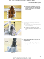
7.
With the stabilizer plate removed, the steering gear,
and spacer can be removed. See Figure 3.17.
Figure 3.17
Bushing
Steering Link Rod
There is a removable bushing between the stud on the
steering gear and the steering link rod. One side of the
bushing is a flat shoulder, the other side is tapered and
barbed. The flat shoulder faces the gear when installed
correctly. See Figure 3.18.
Figure 3.18
17
www.mymowerparts.com
For Parts Call 606-678-9623 or 606-561-4983
700 Series Lawn Tractor
Assembly notes:
•
Replace any locking fasteners that show signs of wear or reduced locking function. In some cases, the
parts may be thoroughly cleaned and locked with re leasable thread locking compound such as Loctite
242 (blue).
•
Replace the hex bushing that locates the steering shaft, the spacer at the center of the steering gear, and
the bushing on the end of the drag link to tighten-up sloppy steering, in addition to confirming that the
gears, wheel bearings, and axle bushings are in good condition.
•
Apply grease such as MTD P/N 737-0300A (Benelene), or anti-seize compound, to the friction surfaces and
teeth of the steering gear on assembly.
•
Make a visual inspection of the steering gear and pinion gear, paying particular attention to the condition of the
teeth. If either are worn or damaged, replace both gears and any suspect bushings and hardware.
•
Apply anti-seize compound to the bearing surface at the base of the steering shaft.
•
The screw that secures the bottom of the steering shaft should be thoroughly cleaned and locked with re leasable thread locking compound such as Loctite 242 (blue). Tighten it to a torque of 17-20 ft.-lbs (23-27 Nm).
•
The screw that secures steering wheel to the steering shaft should be thoroughly cleaned. Re leasable thread
locking compound such as Loctite 242 (blue) should be applied to the threads. Tighten it to a torque of 17-20
ft.-lbs (23-27 Nm).
•
Tighten the steering gear shoulder bolt (passes through the curved slot in the steering gear) before tightening
the steering gear pivot bolt (passes through the spacer at the center of the steering gear).
•
The steering gear shoulder bolt should be tightened to a torque of 200-260 in-lb. (22.6-29.4 Nm).
•
The steering gear pivot bolt should be tightened to a torque of 200-260 in-lb. (22.6-29.4 Nm).
•
The ball joint nuts should be tightened to a torque of 150-250 in-lb. (17-28 Nm) after removal or adjustment.
7.1.
Thoroughly test the steering before returning the tractor to service:
•
Test for ease and freedom of movement.
•
Check for loose operation or hardware.
•
Turn to full-lock in both directions to check linkage travel and steering gear.
18
www.mymowerparts.com
For Parts Call 606-678-9623 or 606-561-4983
Steering and Front Axle
Steering Link Rod Replacement
If the right wheel strikes an object hard enough, the
steering link could bend. If the steering link rod is bent,
inspect the other components for damage and replace as
necessary.
Flanged Lock Nut
To replace the steering link rod:
Figure 3.19
Loosen jam nut
1.
Raise the hood to gain access to the steering components behind the engine.
2.
If desired, move the fuel tank and the fuel tank support bracket out of the way. See instructions in the
steering gear replacement section of this chapter.
3.
Remove the flange lock nut that fastens the steering
link rod to the steering gear. Lift the rod up and out of
the way. See Figure 3.19.
NOTE: There is a flange bushing inserted through the hole
in the rod. Inspect for wear and replace if needed.
Note the orientation of the steering rod and bushing.
4.
Loosen the jam nut that locks the ball joint in position
on the steering arm at the front axle. Hold the ball
joint using a 1/2” wrench, and loosen the nut using an
11/16” wrench. Back the jam nut away from the ball
joint a few turns.
5.
Remove the steering arm from the axle as described
in the axle bushing replacement procedure.
Remove steering arm
NOTE: This is preferable to separating the ball joint from
the steering arm because the center-locking nut
that secures the ball joint to the steering arm distorts the threads on installation. If you choose to
remove the ball joint from the steering arm you will
need to replace it.
Figure 3.20
Bushing
Steering Link Rod
6.
Unscrew the ball joint from the steering link rod.
NOTE: Make note of the orientation of the rod during disassembly.
7.
Install a new flange bushing in the new steering arm.
See Figure 3.21.
8.
Install the rod in the reverse order of disassembly.
NOTE: The end of the steering link is off-set and coined
flat. The side of the off-set end that is steppeddown faces away from the steering gear. Otherwise the drag link will interfere with the steering
gear when connected to the steering arm and axle.
9.
Perform a front wheel alignment as described in the
next section.
Figure 3.21
19
www.mymowerparts.com
For Parts Call 606-678-9623 or 606-561-4983
700 Series Lawn Tractor
Front wheel alignment
Normally a tractor will only be out of alignment if it has been in a accident and a component has been bent or
damaged. Another need for an alignment would be when steering or front end components are being serviced.
The toe-in is set in a fixed position due to the fixed length of the rod connected between the right and left axles.
During assembly at the factory the steering gear is assembled with an equal number of teeth showing on both
sides of the steering shaft pinion gear. There is a centering hole in the bottom of the steering gear that is lined up with
a hole in the frame. The steering shaft and pinion gear are then installed.The steering wheel is then attached with the
steering wheel spokes centered.
NOTE: A mis-adjusted steering link may leave the steering gear off-center, giving the tractor a maximum turning radius that is shorter in one direction and longer in the other.
View the steering gear from behind the engine and below the fuel tank. Turn the steering wheel until and equal
number of steering gear teeth are on each side of the steering shaft pinion gear.
The steering gear is now centered and the front wheels should be facing straight ahead.
If the front wheels are not facing straight ahead, the steering link will need to be adjusted to bring the front wheels
into alignment.
To adjust the steering link:
1.
Center the steering gear as described above.
2.
Loosen the jam nut that locks the ball joint in position. Hold the ball joint using a 1/2” wrench, and
loosen the nut using an 11/16” wrench.
See Figure 3.22.
3.
After the jam nut is loosened, remove the steering
arm from the axle as described in the axle bushing
replacement procedure.
Loosen jam nut
NOTE: This is preferable to separating the ball joint
from the steering arm because the centerlocking nut that secures the ball joint to the
steering arm distorts the threads on installation.
Remove steering arm
Figure 3.22
4.
Manually position the front wheels until they are
pointing straight ahead.
5.
Rotate the steering arm and ball joint to thread them up or down the steering link as necessary to align the
steering arm with the axle.
6.
Test-fit the steering arm to confirm alignment.
7.
Once positioned tighten the steering arm clamp bolt to a torque of 200-260 in-lb. (22.6 Nm-29.4 Nm).
NOTE: Replace the nylon ring lock nut if it has lost its retaining capabilities.
8.
Center the ball joint in its travel, so it does not bind, and tighten the jam nut that secures it.
9.
Inspect the steering wheel and determine that it is pointing straight ahead.
20
www.mymowerparts.com
For Parts Call 606-678-9623 or 606-561-4983
Steering and Front Axle
If the steering wheel needs adjustment:
1.
Remove the steering wheel cap with a screwdriver.
See Figure 3.23.
2.
Using a socket remove the hex nut and bell washer
that fastens the steering wheel to the shaft.
3.
Remove the steering wheel and turn it until the
spokes are centered.
4.
Reinstall the steering wheel onto the splined shaft.
5.
Install the bell washer, hex nut, and steering wheel
cap, in that order.
• Test the operation of the steering system before
returning the tractor to service.
Figure 3.23
21
www.mymowerparts.com
For Parts Call 606-678-9623 or 606-561-4983
700 Series Lawn Tractor
22
www.mymowerparts.com
For Parts Call 606-678-9623 or 606-561-4983
Body Panels
CHAPTER 4: BODY PANELS
What is covered by this chapter
The intent of this chapter is to describe the removal and disassembly of the major body panels on the tractor.
•
Hood
•
Seat
•
Fenders
•
Dash panel
NOTE: It is not absolutely necessary to remove the mowing deck for any procedures covered in this section.
The technician may choose to remove the mowing deck so that it is easier to reach some parts of the
tractor.
Hood Removal
NOTE: The hood described in this section is the “S” style hood. Other hood styles are used on different models. Most of these models are front hinged but may have a different hood mounting bracket depending
upon the engine used on the rider. The “2” style hood is a multi-piece hood with a front pivot near top of
the grill assembly. Refer to the illustrated parts list as a reference for removing that hood or additional
illustrations.
1.
The hood is front-hinged. See Figure 4.1.
2.
Open the hood by lifting the rear edge to tilt it forward.
“S” style hood
Figure 4.1
23
www.mymowerparts.com
For Parts Call 606-678-9623 or 606-561-4983
700 Series Lawn Tractor
3.
Rotate each headlight lamp socket to release them
from the grill assembly. See Figure 4.2.
Bayonet style connector
Figure 4.2
4.
Cut the plastic wire tie that secures the headlight
harness to the hood bracket. See Figure 4.3.
NOTE: Some hood configurations have a wire harness that does not use a wire tie to secure it
to the hood.
5.
Set the harness out of the way on the frame of the
rider.
Wire Tie
Figure 4.3
6.
Open the hood far enough to align the tabs with the
opening in the slots, then lift the hood off of the tractor. See Figure 4.4.
Tab
Hood Bracket
NOTE: The hood hinges on a pair of shoulder bolts
that fit into slots in the hood bracket. The
hinge travel is limited by a tab that fits into a
channel in the hood bracket.
Shoulder Bolt
Figure 4.4
24
www.mymowerparts.com
For Parts Call 606-678-9623 or 606-561-4983
Body Panels
Hood components
Headlight bezels, grills, pivot brackets and other parts
attach to the hood using screw fasteners. The many varieties of hood styles does not allow a thorough description of
procedures in this service manual. Refer to the illustrated
parts list for your particular rider for reference. In many
cases part numbers are imprinted on plastic parts to aid in
identification. See Figure 4.5.
Figure 4.5
Seat and Fenders
There are four variants of fender used on the Cub Cadet Series 1000 for the model year 2009 and after:
•
Manual PTO models have two levers on the right fender: one for the deck height control and one for the
PTO.
•
Electric PTO models have one lever on the right fender to control the deck height.
•
CVT-drive tractors (single-speed transmission + variable speed pulleys) use fenders with a single pedal
opening on each side: clutch/brake on the left, drive pedal on the right. In addition, a forward-neutralreverse lever is on the left fender.
•
Hydrostatic-drive tractors use fenders with a single pedal opening on the left, and two openings on the
right. The clutch/brake pedal is on the left, with two pedals on the right; one to control forward drive, and
the other to control reverse drive.
NOTE: Removing the fenders offers easier access to:
•
Parts of the drive system
•
Deck engagement and deck lift components.
•
Drive tensioner pivot bracket bolt (some models).
25
www.mymowerparts.com
For Parts Call 606-678-9623 or 606-561-4983
700 Series Lawn Tractor
Seat Removal
NOTE: The fenders can be removed with the seat in place. You only need to remove the seat if you are replacing it.
Depending upon the model there are four ways that the seat may be mounted on the rider.
•
The seat has two integrated plastic mounting flanges that slide into the pivoting seat bracket. The seat is
secured in the desired position with a hex flange bolt.
•
The seat has two shoulder screws attached to the seat which slide into the pivoting seat bracket.The seat
is secured in the desired position with a hex flange bolt.
•
The seat has either of the two mounting fasteners mentioned above on the seat and is secured in the
desired position by a plastic knob to allow easy seat adjustment.
•
The seat is adjustable by the operator by moving a lever under the seat to the left and sliding the seat to
the desired position, releasing the lever and moving the seat slightly until it catches in the latch on the
lever.
To remove the fixed position seat:
1.
Tilt the seat up.
2.
If you are simply replacing a damaged seat, remove the fastener/s securing the seat to the seat bracket.
3.
Slide the seat until the seat can be removed from the pivoting seat bracket.
4.
Install the new seat in the reverse order of disassembly.
Replacing an adjustable seat:
1.
Tilt the seat up.
2.
Remove the two hex screws securing the spring
steel seat stop to the pivoting seat bracket.
See Figure 4.6.
3.
Set the parts aside.
4.
Push the seat adjustment lever to the left while at
the same time sliding the seat up until it slides out of
the pivoting seat bracket.
5.
Replace the seat in the reverse order of disassembly.
Hex Screws
Spring Steel Seat Stop
Figure 4.6
26
www.mymowerparts.com
For Parts Call 606-678-9623 or 606-561-4983
Body Panels
Seat bracket removal
1.
Tilt the seat up.
2.
Remove the two wiring harness connectors from the
seat safety switch. See Figure 4.7.
3.
Using a screwdriver or pliers, pry the extension
spring from the rear of the seat mounting bracket.
See Figure 4.8.
4.
Remove the spring from the seat mounting bracket.
5.
Remove the four hex screws and lock washers fastening the two seat mounting brackets to the frame.
6.
Install the seat bracket and seat in the reverse order
of disassembly.
Wiring Harness Connectors
Figure 4.7
Figure 4.8
27
www.mymowerparts.com
For Parts Call 606-678-9623 or 606-561-4983
700 Series Lawn Tractor
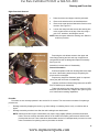
Fender Removal
Removal procedures for fenders are very similar on all variants.
NOTE: The battery will be removed in this procedure. Review the Operator’s Manual and the Chapter on Electrical Systems for important safety information about handling batteries before proceeding.
To remove the fenders:
1.
Pivot the seat up.
NOTE: It is not necessary to remove the seat from
the rider in order to remove the fenders.
2.
Remove the battery from the rider. Refer to the battery removal section of this manual.
3.
Remove the battery support brackets from the seat
frame.
4.
Disconnect the wiring harness connectors attached
to the seat safety switch. See Figure 4.9.
Figure 4.9
5.
Remove the right and left footpads by carefully prying the plastic fasteners from the fender. Set them
aside. See Figure 4.10.
Figure 4.10
28
www.mymowerparts.com
For Parts Call 606-678-9623 or 606-561-4983
Body Panels
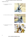
6.
Locate the two hex head screws that attach the
fender to the lower frame. See Figure 4.11.
NOTE: These fasteners are under the safety decal
adhered to the center of the fender between the
operators legs.
7.
Using a small knife, cut around the head of each
screw.
8.
Remove the two screws.
9.
Remove the carriage bolt, flat washer and nut securing the front portion of the fender to the running board
bracket. Do this on both the left and right side of the
fender. See Figure 4.12.
Hex screws under label
Figure 4.11
Carriage bolt, washer and hex screw
Figure 4.12
Remove rubber grip
10. Remove the knob from the shift lever on the left rear
side of the fender.Twist the knob to remove it.
11.
Lift adjuster plate
Remove the rubber grip from the PTO engagement
lever on the right side of the fender. A blow-gun with
air pressure regulated to less than 25 PSI (1.72
Bars). may be inserted into the small hole at the end
of the rubber grip to inflate it slightly, easing removal.
See Figure 4.13.
! CAUTION
Torx head screws
Figure 4.13
Use caution during this
step.Wear safety glasses to
protect your eyes from debris.
12. Remove the two Torx head screws securing the lift
adjuster bracket plate to the fender. Remove the
plate. See Figure 4.13.
29
www.mymowerparts.com
For Parts Call 606-678-9623 or 606-561-4983
700 Series Lawn Tractor
13.
Remove the extension spring that attaches between
the shift lever and the hole in the seat frame bracket
below the left fender. See Figure 4.14.
Extension Spring attached through hole in frame
Figure 4.14
14.
From under the fenders, remove the four hex screws
that secure the seat frame bracket to the frame
assembly. See Figure 4.15.
15.
With a helper, carefully lift the fender up and back
from the rear of the rider.
16.
Assemble the fender in the reverse order of disassembly.
Hex Screws
Figure 4.15
30
www.mymowerparts.com
For Parts Call 606-678-9623 or 606-561-4983
Body Panels
Dash Panel
The dash panel will typically only need to be removed if it is damaged. The dash assembly has a lower portion
made of painted steel and a upper portion made of plastic. The upper portion is molded to accommodate the many
different hood designs used on the 700 series riders. The steel portion comes in several styles, some designed to
accommodate the RMC (mow in reverse) module and some without. You can replace the upper portion of the dash
without removing the lower portion.
To remove the upper dash:
Upper dash screws
1.
Open the hood.
2.
Remove the two hex screws under the dash securing
the upper dash to the lower dash. See Figure 4.16.
3.
Remove the two hex screws (one on each side)
securing the sides of the upper dash panel to the
lower dash panel. See Figure 4.17.
4.
Remove the upper dash.
5.
Install in the revers order of disassembly.
Figure 4.16
Dash panel screw
Figure 4.17
31
www.mymowerparts.com
For Parts Call 606-678-9623 or 606-561-4983
700 Series Lawn Tractor
To remove the lower dash
1.
Remove the upper dash. (see above)
2.
Remove the steering wheel
2a.
Locking tabs
Remove the cap from the center of the steering wheel. See Figure 4.18.
NOTE: The cap can be released by prying-in on the
lock-tabs on the under-side of the cap.
2b.
Remove the bolt and bell washer that holds
the steering wheel to the steering shaft using
a 1/2” wrench.
2c.Lift the steering wheel off of the shaft.
3.
4.
5.
Remove the fuel tank. Refer to the section on fuel
tank removal.
Steering wheel bolt and bell washer
Figure 4.18
Remove the three hex screws under the dash
securing the steering support to the lower dash
panel. See Figure 4.19.
Hex screws
Remove the steering support.
Figure 4.19
6.
Disconnect all wiring harness plugs from dash
mounted components See Figure 4.20.
This may include:
7.
•
Hour meter
•
Key switch
•
RMC module
•
PTO switch, if so equipped
•
Parking brake safety switch
Remove any dash mounted components. The key
switch, hour meter and RMC module can be popped
out using a screwdriver to depress the tabs securing
them to the dash.
Back side of RMC module
Figure 4.20
32
www.mymowerparts.com
For Parts Call 606-678-9623 or 606-561-4983
Body Panels
Mark ferrule for installation
8.
Remove the choke/throttle lever following the directions in Chapter Two.
9.
Remove the parking brake lever.
NOTE: On some models this is also used as a speed control lever.
Parking brake bow tie clip
9a.
Remove the bow tie pin securing the parking
brake rod ferrule to the speed latch.
See Figure 4.21.
NOTE: Mark the position of the ferrule on the rod to ease
reassembly.
Figure 4.21
Torx head screws
9b.
Remove the two Torx head screws securing the
parking brake lever assembly to the dash. See
Figure 4.22.
9c.
Remove the assembly from the dash.
Figure 4.22
10. Remove the hex cap screw securing the lower portion of the dash brace rod to the frame.
See Figure 4.23.
NOTE: The rider you are working on may not have this
brace.
Dash brace
Figure 4.23
33
www.mymowerparts.com
For Parts Call 606-678-9623 or 606-561-4983
700 Series Lawn Tractor
11.
Hex cap screws
Remove the two hex cap screws securing the lower
dash to the right frame of the rider. See Figure 4.24.
Figure 4.24
12.
Remove the two hex screws securing the lower
dash to the left side of the frame.
Hex cap screws
NOTE: Before doing so, loosen, but do not remove,
the flanged hex lock nut securing the parking
brake latch to the frame.
13.
Lift the dash up and away from the steering shaft.
14.
Assemble the dash to the rider in the reverse order
of disassembly.
Loosen flanged hex lock nut
Figure 4.25
34
www.mymowerparts.com
For Parts Call 606-678-9623 or 606-561-4983
Auto-Drive CVT Drive System
CHAPTER 5: AUTO-DRIVE CVT DRIVE AND BRAKE SYSTEM
About this chapter
The drive and brake systems for the 700 Series tractor are combined. There are two reasons for this:
•
The brake is supplied with the transaxle.
•
The brake pedal applies the brake and disengages the drive system. Both systems share common linkage.
The transaxle used in the 700 Series is a relatively simple gearbox containing forward, neutral, and reverse
gears. The variation in speed is all handled by the variable speed pulley system that drives the transaxle.
If the tractor has drive system problems within the warranty period, the servicing dealer has the following responsibilities:
•
Eliminate any external causes for drive system problems before removing the transmission from the tractor.
•
External problems would include, but are not limited to: belt, linkage, or brake issues.
•
Look for signs or over-use or abuse. Transaxles that fail because of over use or abuse are not warrantable. They are to be repaired or replaced at the customer’s expense.
•
If the problem is internal, the transmission is to be replaced under the like-kind exchange policy.
•
If a transaxle is replaced under warranty, the original transaxle may be called-back for evaluation by MTD
Vendor Recovery Dept.
•
Warranty Claims will be denied, returned, or adjusted if the returned transaxle does not meet MTD
replacement criteria.
•
Servicing centers are encouraged to open transaxles for inspection, allowing them to identify a problem
within the transaxle.
•
Beyond warranty, service centers are free to repair transmissions at customer expense.
•
If the service center has questions regarding transaxle replacement, they should call the MTD Customer
Support Center before proceeding.
35
www.mymowerparts.com
For Parts Call 606-678-9623 or 606-561-4983
700 Series Lawn Tractor
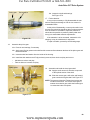
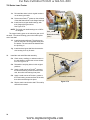
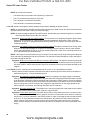
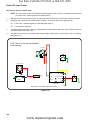
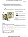
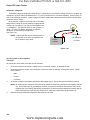
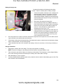
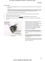
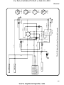
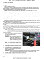
About the variable speed drive system
There are two drive belts in the system. A long drive
belt transfers power from the engine crankshaft to the
lower sheave of the variable-speed pulley. A shorter belt
fits in the upper sheave of the variable speed pulley; transferring power from there to the input pulley on the transaxle. See Figure 5.1.
Variable Speed Pulley
Lower Drive Belt
Upper Drive Belt
Figure 5.1
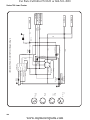
•
The drive control pedal tensions the front drive
belt using a pivoting double idler bracket.
See Figure 5.2.
•
The center partition of the variable speed pulley
separates the lower (front) belt from the upper
(rear) belt.
Double Idler Bracket
Drive pedal bracket
•
As the front belt is tensioned, it is drawn deeper
into its sheave. The effective circumference of
the driven pulley shrinks.
•
As the front belt is drawn deeper into its
sheave, the center partition is forced upward,
making the upper sheave narrower.
•
As the upper sheave pinches-down on the rear
drive belt, the belt is forced outward in the
sheave. The effective circumference of the pulley driving the rear belt grows.
•
As the upper and lower sheaves change size, the drive ratio shifts increasing the speed of the rear belt.
•
The upper drive belt is kept under constant tension by a pivoting idler arm with a pulley and a tension
spring.
•
When the clutch/brake pedal is applied it takes tension off the front double idler bracket, releasing tension
on the belt and applying the brake on the transmission.
Figure 5.2
36
www.mymowerparts.com
For Parts Call 606-678-9623 or 606-561-4983
Auto-Drive CVT Drive System
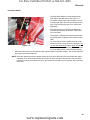
Externally repairable drive system problems:
Most of the problems listed in this section will result in a customer complaint of low power or low ground speed. If the
tractor is difficult to push, check the brakes.
1.
2.
Engine performance:
•
If the engine does not turn at the specified RPM, the tractor will not travel at its designed speed.
•
If the engine does not produce the specified amount of power, the tractor will not have its designed
amount of tractive force.
1a.
Find the specified engine RPM for the tractor.
1b.
Check the engine with a tachometer to confirm that it maintains the specified RPM under normal load.
1c.
Correct engine performance problems before trying to diagnose drive system problems.
Check the tire pressure: Under-filled tires will put additional load on the drive system.
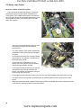
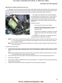
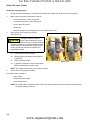
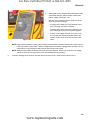
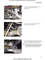
3.
Brake Rod
Check the brakes:
3a.
Double Idler
The brake linkage applies the brakes and disengages the drive belt. Confirm that both parts
of the linkage are moving properly.
See Figure 5.3.
• When the brake pedal is released, the front drive
belt should be slightly slack.
Brake/Clutch bypass rod de-clutches
idler when brake is engaged
Brake Pedal
• The drive and brake linkages are connected in
such a way that the pedals will “see-saw”, and it
should not be possible to apply drive and clutch/
brake pedal at the same time.
Figure 5.3
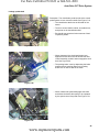
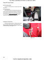
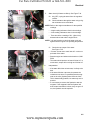
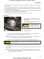
Brake rod
3b.
Brake spring
Brake yoke
Brake arm
If the linkage is working properly, but the brakes
seem to be dragging, check the brake yoke.
The linkage is not adjustable. See Figure 5.4.
• When the brakes are released, it should be possible to wiggle the brake rotor within the yoke.
• If the rotor is tight in the caliper, check the yoke
adjustment.
• If the rotor is tight in the yoke, check the operation
of the yoke to confirm that it is not stuck.
• When the brake pedal is released, the brake arm
on the yoke should fall completely back against the
axle housing.
Adjustment nut
Figure 5.4
37
www.mymowerparts.com
For Parts Call 606-678-9623 or 606-561-4983
700 Series Lawn Tractor
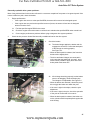
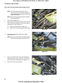
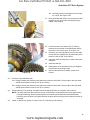
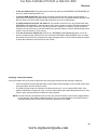
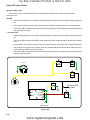
4.
5.
Double idler
Check the drive belts.
•
In normal use, drive belts typically last for years
without problems.
•
If the belt fails prematurely, identify and correct
the cause of the belt failure before returning the
tractor to service.
4a.
Look up the part number for the belts, and
confirm that the correct OEM belts are on the
tractor.
4b.
Check the belt routing. See Figure 5.5.
4c.
Check the brake/clutch linkage and belt tensioning pulleys.
4d.
Check for foreign objects jammed against the
belt.
Belt inside of guides
Belt outside of guide
Look for debris
Figure 5.5
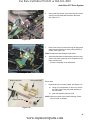
4e.
Check for missing or out-of-place belt guides.
See the belt replacement section of this chapter.
4f.
Check the engine crankshaft and transaxle input pulleys; Confirm that the sheaves are not spread-out,
causing a loose belt fit.
Check the drive control linkage. See Figure 5.6.
5a.
The drive pedal bracket assembly has stops
for the released position and fully depressed
position. The pedal bracket should have
enough travel for the full range of motion.
5b.
Some relatively simple things that may go
wrong with the pedal linkage:
•
The drive pedal itself being loose on the
bracket.
•
Worn plastic bushings between the drive pedal
shaft and the concentric brake cross-shaft.
Drive pedal bracket
Stop for released position
Stop for depressed position
Figure 5.6
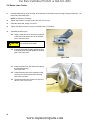
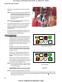
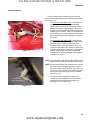
6.
Transmission Mounting Bolts
Transaxle mounting:
6a.
The primary symptoms of a transaxle that is
loose in the frame are that it will lose drive or
throw-off the upper drive belt in reverse.
6b.
Check the transmission mounting points on
the frame and torque bracket. See Figure 5.7.
6c.
If there is no drive in either direction, check
the gear selector adjustment. Refer to the
selector adjustment section later in the chapter.
Figure 5.7
38
www.mymowerparts.com
For Parts Call 606-678-9623 or 606-561-4983
Auto-Drive CVT Drive System
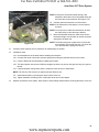
Indications that a transaxle is not warrantable
Anything that would indicate misuse, abuse, neglect, accident, improper maintenance, alteration, vandalism,
theft, fire, water or damage because of other peril or natural disaster will render the transaxle non-warrantable even
though it is within the normal warranty period.
Typical indicators of a void warranty would be:
•
Tractor is beyond the warranty period.
•
Abnormally high wear indicators for the age of the tractor (usually consistent with high hours of usage). As
an example, if the tires are completely worn-out on a tractor that is 6-months old, it is reasonable to think
it has been used pretty heavily even if the hour meter has been unplugged.
•
Bent axle, broken housing, or other obvious signs of impact damage
•
Indication that the tractor has been over-loaded or used with ground engaging attachments.
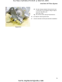
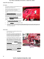
Brake
Brake rod
Brake return spring
Brake assembly
A foot pedal on the left side of the tractor controls the
brake. It engages the brake when it is depressed. If the
brake fails to stop the tractor or hold it on a hill, the brakes
must be checked and adjusted.
Visually inspect the brake pedal linkage to confirm that
it functions properly. See Figure 5.8.
• At rest, the brake foot pedal stop should be against
the frame.
Brake pedal assembly
• When the brake pedal is depressed, the bracket
on the pedal assembly rotates forward, pulling the
brake rod forward and engaging the brake on the
transmission.
Figure 5.8
• The parking brake engagement lever is on the left
side of the dash. A brake control rod passes down
through the dash and connects to a brake latch on
the frame.
• When the brake is fully depressed, the parking
brake lever can be rotated downward engaging the
brake latch and holding the brake pedal in the
engaged position. See Figure 5.9.
• Depressing the brake foot pedal and raising the
parking brake lever to the run position releases the
parking brake.
Figure 5.9
• When the brake is released the rod connecting the
brake pedal assembly to the brake actuator spring
at the transmission should be just slack.
39
www.mymowerparts.com
For Parts Call 606-678-9623 or 606-561-4983
700 Series Lawn Tractor
If the parking brake does not engage, check the following:
1.
Check for a bent parking brake rod where it passes
down through the dash. See Figure 5.10.
2.
Check that the ferrule is connected to the brake
latch and is secured with a bow tie clip.
3.
Check that the brake latch is not bent and not making contact with the brake pedal latch bracket.
4.
If necessary, adjust the length of the ferrule to allow
the latch to lock the brake pedal when engaged.
Parking brake rod
Adjustment ferrule
Brake latch
Testing the operation of the brake:
1.
Put the transaxle in neutral.
2.
Set the parking brake by depressing the brake/
clutch pedal and pushing-down on the parking brake/cruise control lever.
3.
Attempt to push the tractor. If it can be pushed by hand without skidding a rear wheel, adjust the brake.
4.
Release the parking brake.
5.
Attempt to push the tractor again. If it cannot be pushed with little effort, adjust the brake.
Figure 5.10
Brake adjustment
1.
2.
Check the gap between the brake rotor and the
brake pads. See Figure 5.11.
•
There is a fixed pad in the transaxle housing.
•
There is a moving pad in the brake caliper.
Check gap between rotor and pad
Wiggle the brake rotor slightly, and attempt to insert
a .010” (.38mm) feeler gauge between the rotor and
either pad.
2a.
Adjust the gap, if necessary, so that the feeler
gauge slips between the pad and the rotor
with light pressure.
2b.
Turn the nut to adjust the gap. The gap should
be in the range of .010”-.015” (.25mm-.38mm)
•
Figure 5.11
Apply and release the brake pedal, then re-check the gap.
2c.
If the brake seems to be sticking, or the rotor is discolored from dragging, remove the brake yoke for
repair or replacement.
2d.
Set the parking brake. The front drive belt should be slack.
2e.
Re-test the operation of the brakes before returning the tractor to service.
40
www.mymowerparts.com
For Parts Call 606-678-9623 or 606-561-4983
Auto-Drive CVT Drive System
Gear selector
Shift lever
• The forward-neutral-reverse gear selector is on the
left rear fender of the tractor. See Figure 5.12.
Shift adjustment bracket
Shift rod
Figure 5.12
• A spring under the fender attached between the
seat frame bracket and the shift lever keeps inward
pressure on the selector to give it positive feel.
See Figure 5.13.
Extension spring
• The selector pivots on a frame-mounted bracket,
transferring the motion to a push-pull detent rod
connected to the transaxle.
Figure 5.13
• The linkage contacts the reverse safety switch
tang when the tractor is in reverse.
See Figure 5.14.
• The linkage is adjustable.
Figure 5.14
41
www.mymowerparts.com
For Parts Call 606-678-9623 or 606-561-4983
700 Series Lawn Tractor
Adjusting Gearshift Lever
If the gearshift lever does not line up with the neutral position on the fender or the operator has trouble putting the
tractor in one of the gear positions because the lever hits the fender, the position of the gear shift lever can be
adjusted.
1.
To adjust the gearshift linkage, adjust the shift lever
rod where it enters the transmission to the center
detent position. See Figure 5.15.
2.
Confirm that the tractor is in neutral by releasing the
brakes and rolling it back and forth.
Figure 5.15
3.
Loosen the adjustment bolt on the shift bracket
using a 1/2” wrench. See Figure 5.16.
4.
Place the gear selector handle so that it is fully
seated in the N notch on the fender.
5.
Tighten the adjustment bolt and re-check the position of the gear selector.
6.
Move the gear selector into the forward position to
make sure the tractor goes into gear.
Adjustment bolt
NOTE: The tractor may need to be rocked slightly
forward or back to engage it in gear.
7.
Move the gear selector to the reverse position to
confirm that it is in the reverse position.
Figure 5.16
NOTE: The tractor may need to be rocked slightly
forward or back to engage it in gear.
8.
Place the gear selector in the neutral position and confirm that it is in neutral by rolling it along the ground.
42
www.mymowerparts.com
For Parts Call 606-678-9623 or 606-561-4983
Auto-Drive CVT Drive System
Adjusting the variable speed pulley control rod
An adjustable rod connects the foot pedal assembly to the variable speed pulley assembly. This adjustment sets
the neutral position of the idler pulley and the top speed of the tractor. Pressing on the drive pedal tensions the belt
between the engine pulley and the variable speed pulley and changes the ground speed of the tractor.
See Figure 5.17.
The length of the adjustment rod is set at the factory
during assembly. it is nominally set at 7.5” Inches. End of
line testing assures that the tractor will not creep when
stopped in gear and yet still achieves maximum drive
speed. Creep is the primary safety concern and must be
corrected.
Reasons for creep:
7.5”
• A bent rod due to some sort of collision.
• Improper belt installed on the tractor. A shorter, or
wider, belt may be engaging the drive when
stopped in gear.
Figure 5.17
• Adjustment rod shortened in a attempt to increase
forward ground speed and inadvertently creating
creep.
The length of the adjustment rod may also need to be
changed when the drive belts are replaced.
NOTE: In some cases a customer may complain that the tractor does not seem to be going as fast as it used
to. The cause may be attributed to belt wear and stretching. If that is the case, this would be a good
time to replace the belts.
NOTE: As a general rule, shortening the adjustment rod increases the ground speed of the tractor but doing
so can cause creep.
To adjust a tractor with creep:
1.
Confirm the creep yourself by starting the tractor with the parking brake engaged. Place the tractor in forward
gear and slowly release the brake/clutch pedal. keep you foot off the drive pedal. The rider should not creep or
move.
NOTE: If the transmission grinds when going into gear, that is another indicator that the drive belt is moving
and the adjustment rod length needs to be changed.
2.
If the rider creeps, turn off the engine, block the wheels of the rider in neutral with the parking brake off.
3.
Remove the cutting deck.
4.
Confirm that the belts are OEM belts and are in good condition. If not, replace both drive belts as described in
belt section in this chapter.
5.
Inspect the link and the double idler pulley system for any obvious signs of damage.
43
www.mymowerparts.com
For Parts Call 606-678-9623 or 606-561-4983
700 Series Lawn Tractor
6.
Measure the length of the adjustment link to see if it
is at the factory specification, 7-1/2”.
See Figure 5.18.
NOTE: Lengthening the adjustable rod to factory
specifications (or longer) should eliminate
the creep.
7.
Loosen the link jam nut securing the ball joint to the
adjustable rod using a 9/16” wrench.
8.
Remove and discard the cotter pin that holds the
plain end of the adjustment rod to the cobra head
arm on the pedal shaft.
9.
Remove the rod from the cobra head arm and move
the arm back towards the rear of the tractor. This
will give you room to rotate the rod on the ball joint.
7-1/2”
Cobra Head Arm
Figure 5.18
10.
Secure the drive control pedal in its most rearward position. Use a helper or bungie cord if necessary.
11.
Thread the rod out of the ball joint end to lengthen it.
12.
Adjust the rod length so that the cobra head arm fits easily through the hole in the adjustment rod without moving the cobra arm.
NOTE: The drive belt should appear loose at this time.
13.
Fasten the adjustment rod to the cobra arm with a new cotter pin.
14.
Tighten the jam nut.
15.
Test-run the tractor to confirm that the drive and brake systems work correctly before reinstalling the mowing
deck. If the tractor still creeps, you will need to lengthen the adjustment rod again and retest.
16.
Test and repeat until there is no tractor creep.
17.
Install the cutting deck and confirm that all of the safety features work properly.
44
www.mymowerparts.com
For Parts Call 606-678-9623 or 606-561-4983
Auto-Drive CVT Drive System
Linkage: pedal shaft
Drive pedal shaft
Description: The clutch/brake pedal and the drive control
pedal operate on two concentric shafts. See Figure 5.19.
• The clutch/brake shaft runs the full width of the
tractor.
• The drive control shaft is tubular, is installed over,
and pivots on the clutch/brake shaft.
• Each shaft has stops that limit movement of their
respective pedals.
Clutch/brake shaft
Figure 5.19
Double idler is disengaged
when the brake is applied
• When depressed, the clutch/park brake lever
applies the brake and locks the double idler belt
control assembly so that it cannot engage the drive
belt. See Figure 5.20.
• The parking brake is set by depressing the brake
pedal and then pressing down on the parking
brake lever on the left side of the dash.
Clutch/brake bypass lever
Figure 5.20
Idler is free to be controlled
by the speed control lever
• When released the pedal disengages the brake
and allows the double idler pulley to be operated
by the speed control foot pedal. See Figure 5.21.
Bypass lever releases double idler
Figure 5.21
45
www.mymowerparts.com
For Parts Call 606-678-9623 or 606-561-4983
700 Series Lawn Tractor
Drive pedal and brake pedal shaft assembly removal
NOTE: The entire pedal rod assembly can be
removed, or just the side being worked on.
These instructions show how to remove the
entire rod assembly.
Remove hair pin clip and rod from bracket
NOTE: Confirm that the parking brake is released
before starting work.
1.
Remove the mowing deck.
2.
Disconnect the rod that joins the arm at the left side
of the brake/clutch shaft to the drive belt tensioner
pulley bracket. See Figure 5.22.
3.
2a.
Remove and set aside the hairpin clip.
2b.
Remove the rod from the pedal shaft bracket.
Figure 5.22
Remove the clutch/brake pedal return spring.
See Figure 5.23.
NOTE: Note the location where the spring attaches
to the brake pedal bracket and the frame.
Clutch/brake pedal return spring
Figure 5.23
4.
Remove and discard the cotter pin that holds the
double idler pulley control rod to the “cobra head”
arm on the drive control pedal. See Figure 5.24.
5.
Remove the rod from the bracket.
Cotter pin
Control rod
Cobra head
Figure 5.24
46
www.mymowerparts.com
For Parts Call 606-678-9623 or 606-561-4983
Auto-Drive CVT Drive System
Hex screws securing left pedal shaft
6.
Using a half inch socket, remove the two hex screws
securing the left pedal shaft bracket to the frame.
See Figure 5.25.
7.
Remove the two hex screws securing the right pedal
shaft support bracket to the frame using a half inch
socket. See Figure 5.26.
Figure 5.25
Hex screws securing right pedal bracket
NOTE: Support the shaft during this procedure.
8.
As the pedal shafts are lowered away from the frame,
remove the brake rod spring where it attaches to the
brake actuation arm.
• Place the assembly on the workbench.
Figure 5.26
Brake pedal shaft
Drive pedal shaft
Bench work.
1.
Push cap
Plastic bushings
Separate the two concentric shafts. See Figure 5.27.
1a.
Using a tie rod separator or other tool, remove
the push cap securing the pedal assembly to
the main shaft.
1b.
Slide the assembly from the shaft
NOTE: Note the location of the plastic bushings. Check
them for wear or damage.
Figure 5.27
47
www.mymowerparts.com
For Parts Call 606-678-9623 or 606-561-4983
700 Series Lawn Tractor
Re-enforcement bracket
2.
3.
2a.
Disconnect the cobra-head rod from the pedal
shaft tie plate.
2b.
Slip the tie plate off of the cobra head rod.
2c.
Push the hex bushing out of the big end of the
pedal shaft tie plate.
2d.
The hex bushing can be snapped-off of the
brake pedal shaft.
Inspect the pedal shaft components individually.
Replace any parts that are worn or damaged.
•
•
4.
Cobra head arm
Examine the re-enforcement bracket between the
cobra arm and pedal shaft for damage and replace if
necessary. See Figure 5.28.
Hex bushing
Figure 5.28
The plastic bushings that fit between the two
pedal shafts should be replaced any time they
are removed. Lubricate them with a dry PTFE or graphite-based lubricant on assembly. NOT grease.
Replace the push cap and all removed cotter pins with new parts.
Install the pedal shaft assembly by reversing the steps used to remove it, then install the fenders.
NOTE: Lubricate the point where the right support bracket meets the pedal shaft with a good quality lithiumbased grease.
NOTE: It will be easier to install the brake rod spring through the brake actuator arm as you assemble the
pedal rods to the frame.
5.
4a.
Torque the hex screws during assembly to 150-180 inch pounds. (17-20 N-m)
4b.
Check the adjustment of the double idler pulley control rod
4c.
Attach the brake pedal return spring.
Test the drive system and all safety features before returning the tractor to service.
48
www.mymowerparts.com
For Parts Call 606-678-9623 or 606-561-4983
Auto-Drive CVT Drive System
Linkage: Cobra head to control rod tie plate and hex bushing
NOTE: If there is reason to replace the tie plate and hex bushing, it can be replaced without disassembly of
the pedal shafts. The most likely reason for this would be the discovery of damage to the tie plate or
hex bushing while making an adjustment to the tensioner pulley control rod.
Cotter pin
Control rod
1.
Remove the mowing deck.
2.
Remove and discard the cotter pin that holds the tensioner pulley control rod and the tie plate to the
“cobra-head” arm on the drive control pedal shaft.
See Figure 5.29.
3.
Slip the tie plate off of the “cobra-head” arm, and
pivot it downward. See Figure 5.30.
4.
Slip the tie plate off of the hex bushing, and remove
it.
5.
Snap the hex bushing off of the brake pedal shaft.
Cobra head
Figure 5.29
NOTE: The hook on the tie strap goes over the trimmed
section of the flange on the hex bushing.
Hex bushing
6.
Install the tie strap by reversing the process used to
remove it. Use a new cotter pin to secure the idler
control rod to the cobra head.
7.
Test-drive the tractor to confirm that the drive system
is working correctly before returning it to service.
Tie plate
Figure 5.30
49
www.mymowerparts.com
For Parts Call 606-678-9623 or 606-561-4983
700 Series Lawn Tractor
Belt control: Upper drive belt idler arm
The battery will be removed in this
procedure. Review the Operator’s
Manual and Chapter 7: Electrical
Systems for important safety information about handling batteries before proceeding.
! CAUTION
1.
Upper drive belt pulley
Remove the upper drive belt from the make-up tensioner pulley as described in the drive belts section
of this chapter. See Figure 5.31.
Figure 5.31
2.
Unbolt the arm from the torque bracket using a 9/
16” wrench on the top and a 9/16th deep socket on
the bottom. See Figure 5.32.
Unbolt pivot bracket here
Figure 5.32
3.
4.
The arm pivots on a shouldered bushing.
See Figure 5.33.
•
A shoulder bolt threads into the bottom of the
arm, for the tension spring to hook onto.
•
The tension idler pulley bolts to the top of the
arm.
Idler pulley
Shoulder bushing with bolt and nut
pulley bolt
Install the arm by reversing the procedure used to
remove it.
•
•
Lubricate the pivot point with grease or antiseize compound.
One end of the tensioner spring is off-set. The
off-set end connects to the arm.
Shoulder bolt for spring
Figure 5.33
50
www.mymowerparts.com
Idler arm
For Parts Call 606-678-9623 or 606-561-4983
Auto-Drive CVT Drive System
Belt control: Servicing the variable speed pulley
Slide pulley assembly from transmission
NOTE: While it may be possible to remove the variable
speed pulley from the tractor without removing the
transmission from the rider, we do not advise it.
1.
Remove the rear wheels and transmission as
described in another section of this chapter.
2.
On the work bench you can now slide the variable
speed pulley assembly from the transmission.
See Figure 5.34.
3.
Bench repairs:
Figure 5.34
Clamp pulley in vice using
an oversize belt
3a.
Clamp the pulley and bracket assembly into a
vise using a spare drive belt to hold pulley in
place and allow removal of the pulley bolt.
See Figure 5.35.
NOTE: Using a slightly oversize belt may help keep the
pulley from spinning during bolt removal.
3b.
Use a 1/2” wrench to remove the pulley bolt.
3c.
Lift the bracket, belt keeper, and bearing holder
off of the pulley.
3d.
Remove the three screws that fasten the bearing holder to the bracket, and lift away the bearing holder. See Figure 5.36.
3e.
Inspect the bearings and variable speed pulley.
Remove hex bolt
Figure 5.35
Bearing holder and
hex screws
Pulley bracket assembly
• The bearings should turn smoothly, with no
unusual noise.
Bearings
Figure 5.36
51
www.mymowerparts.com
For Parts Call 606-678-9623 or 606-561-4983
700 Series Lawn Tractor
•
The variable speed pulley should spin true in
the bearings.
•
The center partition of the variable speed pulley
should slide up-and-down smoothly.
See Figure 5.37.
•
If the variable speed pulley shows and damage
it should be replaced.
3f.
Reassemble the variable speed pulley by
reversing the steps used to disassemble it.
NOTE: Tighten the bearing holder screws to a
torque of 90-135 in-lbs (10-15 N-m).
Variable speed pulley
Hex bolt
Belle washer
NOTE: Apply thread locking compound such as
LocTiteTM 242 (blue) to the variable speed
pulley bolt. Tighten the bolt to a torque of
150-180 in-lbs (17-20 N-m).
Figure 5.37
4.
Reinstall the variable speed pulley assembly to the transmission and install the transmission to the tractor by
reversing the steps used to remove it.
5.
Run and test the drive system before returning the tractor to service.
52
www.mymowerparts.com
For Parts Call 606-678-9623 or 606-561-4983
Auto-Drive CVT Drive System
Belt control: Double idler tensioner pulleys
The double idler tension pulleys act as a clutch to engage and disengage the drive belt based on the position of
the drive control foot pedal. In addition, when the brake pedal is depressed a bypass rod disengages the idler pulleys
as it engages the brake. It is not possible to engage the drive system when the brake pedal is depressed fully or the
parking brake is engaged. If the tractor creeps when in gear without any input to the drive pedal, the double idler pulley may be out of adjustment. This condition must be corrected and is covered in the Adjusting The Variable Speed
Control of section of this chapter.
NOTE: The double idler tensioner pulleys can be removed
from the rider without removing the fenders.
NOTE: Confirm that the parking brake is released before
starting work.
Double idler bracket
tension spring
1.
Remove the mowing deck.
2.
Remove the tension spring connected between the
idler bracket and the spacer screw mounted to the
transmission torque bracket. See Figure 5.38.
3.
Remove the hairpin clip securing the transmission
bypass rod to the brake pedal assembly rod bracket.
See Figure 5.39.
4.
Remove the rod from the bracket.
Figure 5.38
Remove hair pin clip and rod
Figure 5.39
53
www.mymowerparts.com
For Parts Call 606-678-9623 or 606-561-4983
700 Series Lawn Tractor
5.
6.
Remove the cotter pin securing the idler adjustment
rod to the cobra head rod on the drive pedal bracket
assembly. See Figure 5.40.
Idler adjustment rod
Cobra head rod
Cotter pin
Remove the idler rod from the cobra head bracket.
Figure 5.40
7.
Using a half inch socket, remove the hex bolt securing the center rear idler pulley to the double pulley
bracket. Remove the bolt, lock washer, hex spacer,
pulley and nut from the bracket. See Figure 5.41.
Center rear idler pulley
Figure 5.41
8.
Hex nut secures
double idler bracket
to frame
Remove the plastic cap in the front of the fender
assembly that reveals the upper nut securing the
double idler bracket to the frame. See Figure 5.42.
Figure 5.42
54
www.mymowerparts.com
For Parts Call 606-678-9623 or 606-561-4983
Auto-Drive CVT Drive System
9.
Using a 9/16” wrench on the bottom and a 9/16th
socket on the top, remove the nut and bolt securing
the double idler bracket to the frame.
See Figure 5.43.
NOTE: Support the idler bracket during this procedure.
Remove nut and bolt securing
idler assembly to frame
Figure 5.43
10. Examine the parts for wear or damage and replace
any damaged parts. See Figure 5.44.
Figure 5.44
11.
Assemble in reverse order of disassembly. (ORDER
OF PARTS) See Figure 5.45.
• Lower idler bracket
• Front pulley hex head screw
• Shoulder spacer
• Front pulley with long shaft down
• Hex spacer
• Shoulder spacer
• upper portion of idler bracket
Figure 5.45
12. Lubricate and assemble to frame using a 9/16”
socket and wrench.
13. Replace plastic cap in fender.
55
www.mymowerparts.com
For Parts Call 606-678-9623 or 606-561-4983
700 Series Lawn Tractor
14.
Attach idler adjustment rod to cobra head bracket
with new cotter pin. See Figure 5.46.
15.
Attach transmission bypass rod to brake assembly
bracket and secure with the hairpin clip removed
earlier/
16.
Route the drive belt through the idler pulleys.
17.
Install the rear idler pulley in the opposite order of
disassembly.
18.
Tighten the hex bolt using a 1/2” socket.
19.
Test the drive the tractor, install the cutting deck and
check all safety features before returning the tractor
to service.
Proper belt routing
Figure 5.46
56
www.mymowerparts.com
For Parts Call 606-678-9623 or 606-561-4983
Auto-Drive CVT Drive System
Drive belt replacement
! CAUTION
The battery will be removed in this procedure. Review the Operator’s Manual and Chapter 7:
Electrical Systems for important safety information about handling batteries before proceeding.
NOTE: The variable speed pulley system that drives this tractor counts on interplay between two belts:
•
If one belt fails, replace both belts. One new belt and one partially worn belt will not work the same as two
new belts.
•
Do not us any belt other than the correct OEM part number belt. This drive system counts on an unusual
cross-section shape of the belts. Use of a wrong belt will very likely cause the tractor not to drive properly.
•
Check the tensioner pulley control rod adjustment after replacing belts.
Upper drive belt
1.
Remove the mowing deck.
2.
Set the park brake to release belt tension.
3.
Remove the battery and battery tray by following the
procedures described in Chapter 4: Body Panels.
4.
Remove upper (rear) drive belt: See Figure 5.47.
4a.
Idler tension spring
Release the lateral spring that provides force
for the tension idler pulley.
NOTE: Use a rope or large bent nose pliers to unhook the
spring from the frame.
Figure 5.47
Loosen pulley bolt
4b.
Loosen the idler pulley from its bracket using a
1/2” wrench. See Figure 5.48.
4c.
Lift the pulley far enough to allow the belt to
clear the belt keepers.
Figure 5.48
57
www.mymowerparts.com
For Parts Call 606-678-9623 or 606-561-4983
700 Series Lawn Tractor
4d.
The slack created will allow the upper belt to
slip easily out of the top sheave of the variable
speed pulley and off of the transmission input
pulley. See Figure 5.49.
4e.
Withdraw the belt through the battery opening
under the seat.
Walk belt up and over variable speed pulley
Figure 5.49
5.
Remove the lower (front) drive belt:
5a.
Loosen hex screw
Using a 1/2” socket with an extension, loosen
the hex screw securing the wire belt keeper
around the engine pulley. See Figure 5.50.
Pull in on rod to release from frame
Figure 5.50
5b.
5c.
Pull in on the belt keeper until the wire end is
released from the hole in the frame and rotate
it towards the rear of the rider.
See Figure 5.51.
Rotate back and away from pulley
Remove PTO pulley
Use an air powered impact wrench, if available, to remove the bolt securing the engine/
PTO pulley to the engine crankshaft. Set the
bolt and washer aside.
Figure 5.51
58
www.mymowerparts.com
For Parts Call 606-678-9623 or 606-561-4983
Auto-Drive CVT Drive System
Belt guides
5d.
Lower the pulley and drive belt enough to clear
the belt guards stamped into the frame. See
Figure 5.52.
5e.
Remove the pulley from the crankshaft and set
it aside.
5f.
Using a 1/2” socket, remove the rear flat idler
pulley from the double idler bracket.
See Figure 5.53.
Stamped belt guards
Figure 5.52
Hex spacer that looks like nut
NOTE: Make note of the order of parts. The hex spacer
looks like a nut but is used as a spacer.
Rear idler pulley
5g.
Walk the belt up and over the variable speed
pulley assembly above the transmission. Rotate
the variable speed pulley to help slip the belt
past the belt keepers.
5h.
Install the new lower drive belt in the reverse
order of disassembly.
Belt installation notes
Figure 5.53
Proper belt routing
• Install only correct OEM belts. Incorrect belts may
cause problems that effect the performance and/or
safety of the tractor.
• The belt is routed inside the front spacer bolts.
See Figure 5.54.
• The spacer bolt in front of the double idler bracket
goes between the two courses of the belt.
Two outer guides
• Apply a small amount of anti-seize compound to
the engine crankshaft before installing the crankshaft pulley.
• Apply a small amount of thread locking compound
such as Loctite 271TM (red) to the threads of the
crankshaft bolt.
One inner guide
Figure 5.54
• Tighten the crankshaft bolt to a torque of 36-50 ftlbs (50-68 N-m).
• Thoroughly test the operation of the drive system
and all safety features before returning the tractor
to service.
59
www.mymowerparts.com
For Parts Call 606-678-9623 or 606-561-4983
700 Series Lawn Tractor
Transaxle removal and replacement
! CAUTION
The battery will be removed in this procedure. Review the Operator’s Manual and the Electrical chapter of this manual for important safety information about handling batteries before
proceeding.
1.
Remove the upper drive belt as described in the
drive belt replacement section of this chapter.
2.
Loosen, but do not remove the wheel bolts.
3.
Lift, and safely support the tractor. The rear of the
tractor should be high enough to allow the transaxle
to pass under it.
4.
Remove the rear wheels and spacers.
5.
Disconnect the forward-neutral-reverse gear selector rod from the transmission by removing the hair
pin clip. See Figure 5.55.
6.
Support the transaxle so that it can be lowered out
of the tractor in a controlled fashion.
7.
Remove the two torque bracket hex screws using a
1/2” wrench. See Figure 5.55.
8.
Remove the two hex screws securing the variable
speed pulley bracket assembly to the left side of the
frame. See Figure 5.56.
9.
Take the nuts off of the T-bolts that hold the transaxle to the frame using a 1/2” wrench. Set the nuts
and bolts aside.
Torque bracket screws
Hair pin clip
Figure 5.55
Hex screws securing variable speed bracket
to frame
Transmission
T bolts (2 of 4)
Figure 5.56
60
www.mymowerparts.com
For Parts Call 606-678-9623 or 606-561-4983
Auto-Drive CVT Drive System
Brake actuator spring
Disconnect here during removal
NOTE: At this point, the brake actuator spring is still
attached to the brake rod from the pedal shaft, and
the brake arm on the transaxle. See Figure 5.57.
10. Carefully lower the transaxle out of the tractor.
NOTE: If the transmission has spacers, remove them at
this time.
NOTE: You may need to rotate the transmission to allow
the input pulley to clear the torque bracket.
11.
Figure 5.57
Move the transaxle forward to make some slack in
the brake linkage. Use the slack to unhook the brake
spring from the brake rod.
NOTE: The brake spring has a tighter hook on the brake
arm end than on the brake rod end. It is much easier to disconnect the spring from the rod.
12.
Carefully lift the transaxle onto a workbench for disassembly as needed.
13.
Installation notes:
13a. Check adjustment of the brake before installing the transaxle.
13b. Connect both ends of the brake actuator spring before lifting the transaxle back into the tractor.
13c. Lube the Double-D axle shaft before installing the wheels.
13d. The wheel spacer sleeves are of different lengths: the short one goes on the right, the long one goes on
the left.
13e. If the transmission has spacers where it meets the frame be sure to install them.
NOTE: The 760 and 770 tractors use spacers and the 780 does not.
13f. Install the transaxle by reversing the steps used to remove it.
13g. Tighten fasteners according to the torque table at the end of this chapter.
14.
Operate and test the drive system, brake system, and all safety features before returning the tractor to service
61
www.mymowerparts.com
For Parts Call 606-678-9623 or 606-561-4983
700 Series Lawn Tractor
Transaxle Repair - Bench Work
General Information
If the tractor is still under warranty, a damaged transaxle would be replaced and not repaired. That being said,
dealers are encouraged to check warranted transaxles for a cause of failure. It only take a few minutes to open a
transaxle for inspection. If it prevents a claim from being denied, it is worthwhile.
Transaxles are typically replaced in customer pay situations. If a transaxle is not damaged too badly, it makes
sense to compare the cost of repair to the cost of a new transaxle. The repaired transaxle can be reinstalled, or sold
at a later date.
1.
Assess the damage from the outside;
See Figure 5.58.
1a.
If the tractor is within the warranty period, is
the damage consistent with a warrantable failure?
1b.
If the tractor is beyond the warranty period, is
the transaxle feasible to repair?
1c.
Are the axles bent?
1d.
Is the housing broken from the outside-in?
1e.
Is the housing broken from the inside-out?
1f.
Spin-test:
Figure 5.58
•
Will the input shaft turn in neutral?
•
Will it drive the wheels forward in forward gear?
Hold the brake rotor and check input-shaft back-lash. It should be 0.006”-0.014” (0.15-0.36mm).
•
Will it drive the wheels backward in reverse gear?
Hold the brake rotor and check input-shaft back-lash. It should be 0.006”-0.014” (0.15-0.36mm).
1g.
2.
If it fails the spin test, are the brakes too tight?
If further investigation is required to determine the
cause of the failure or to asses the feasibility of
repair, disassemble the transmission using the following steps:
NOTE: steps #4 through #6 can be skipped if this is
a warranty-related autopsy.
3.
Slide the shift-shaft pillow block off of the shift shaft.
See Figure 5.59.
4.
Remove the detent screw using a 1/4” allen wrench.
Shift shaft
Pillow block
Figure 5.59
62
www.mymowerparts.com
For Parts Call 606-678-9623 or 606-561-4983
Auto-Drive CVT Drive System
5.
Use a magnet, or turn the transaxle upside-down to
remove the detent ball and spring.
See Figure 5.60.
6.
Disassemble the brake:
Detent ball
Detent screw hole
Detent spring
Detent screw
Figure 5.60
6a.
Unhook and remove the brake spring.
See Figure 5.61.
6b.
Unbolt the brake yoke from the transaxle using
a 3/8” wrench. See Figure 5.62.
Figure 5.61
Brake yoke
Figure 5.62
63
www.mymowerparts.com
For Parts Call 606-678-9623 or 606-561-4983
700 Series Lawn Tractor
6c.
Slip the brake rotor off of the brake shaft
(splined end of bevel gear shaft).
See Figure 5.63.
6d.
Inspect the brake shaft and inner brake pad.
NOTE: The inner pad is epoxied in-place, but may
be pried-out for replacement.
Brake shaft
Brake pad (fixed)
Brake rotor
Figure 5.63
6e.
7.
Disassemble and inspect the brake yoke. See
Figure 5.64.
Brake arm
Remove the 13 remaining perimeter screws that
hold the upper transaxle housing to the lower transaxle housing using a 3/8” wrench.
Brake yoke
Brake pins
Backing plate
Brake pad
Figure 5.64
8.
Separate the two housings. See Figure 5.65.
NOTE: The axle shafts will generally be of different
lengths. Mark, or note the orientation of the
differential and axle assembly to the transaxle housing before removing it.
Lower housing
Upper housing
Figure 5.65
64
www.mymowerparts.com
For Parts Call 606-678-9623 or 606-561-4983
Auto-Drive CVT Drive System
Shims
9.
Lift the axle and differential housing out of the transaxle. See Figure 5.66.
10. Note the positions of the shim washers.
Figure 5.66
Differential and axle assembly
11.
Slip the seals, bearings, and washers off of the differential and axle assembly. See Figure 5.67.
NOTE: When correctly installed, the seals fit on the axle
shaft with the lips facing out. Their primary purpose
is to exclude dirt and moisture. Grease does not
tend to migrate past the axle seals.
NOTE: If the transaxle is to be re-built, replace the bearings and seals with new ones.
12. Inspect the differential and axle assembly.
12a. Look for damaged ring gear teeth.
Figure 5.67
12b. With the ring gear held still, turning one axle
should cause the other axle to rotate smoothly
in the opposite direction.
12c. Look for rust or excessive wear on the bearing
contact surfaces.
12d. Problems in any of these areas mean the differential assembly should be replaced.
12e. If this is a warranty-related autopsy, identify the root cause of the problem. If it is not something that was
done wrong at the factory, the problem is not warrantable.
NOTE: MTD does not have a part number for water, and it is not installed at the factory.
65
www.mymowerparts.com
For Parts Call 606-678-9623 or 606-561-4983
700 Series Lawn Tractor
Forward bevel gear
13.
Lift the bevel gears out of the transaxle for disassembly and (mostly) visual inspection.
See Figure 5.68.
Reverse bevel gear
Engagement teeth
13a. Note the placement of the shims on the bevel
gear shaft.
13b. Check the bevel gear teeth (that mesh with
the pinion gear) for wear or damage.
13c. Check the shift collar engagement teeth on
the bevel gears for wear or damage.
13d. Check the inside bearing surface of each
bevel gear for wear or damage.
Shift collar
13e. Check the bevel gear shaft for wear or damage.
Figure 5.68
Shift fork
13f. Check the shift collar and fork for wear.
See Figure 5.69.
13g. Check shift collar teeth and splines for wear or
damage.
14.
Check the interior of the transaxle housings.
14a. If there is heavy gear-tooth damage on the
ring gear of bevel gears, there is likely to be
large debris in the grease. Dispose of the
grease if the transaxle is to be rebuilt.
14b. If there is heavy wear on any of the contact
surfaces, there is likely to be small particles of
metal in the grease. Dispose of the grease if
the transaxle is to be rebuilt.
Teeth
splines
Figure 5.69
14c. If the grease is obviously contaminated with
water or other substances, dispose of the grease if the transaxle is to be rebuilt.
14d. If the transaxle is being warranted, leave the grease and debris in place, after the root cause of the failure is identified.
66
www.mymowerparts.com
For Parts Call 606-678-9623 or 606-561-4983
Auto-Drive CVT Drive System
14e. If the transaxle is repaired, the damage is isolated, and the grease is not contaminated with
anything, it is acceptable to re-use the grease.
See Figure 5.70.
Figure 5.70
Feeler gauges
15.
Inspect the pinion gear and input shaft assembly.
See Figure 5.71.
15a. The pinion gear teeth should not show signs of
heavy wear or damage.
15b. The input shaft should have 0.015”-0.020”
(0.38-0.51mm) end-play, and 0.002”-0.010” runout.
Figure 5.71
16.
Hog ring
If there a reason to take-apart the input pinion, use
the following steps:
16a. Remove the hog-ring pulley stop by pryingopen the end gap and slipping it up the shaft.
See Figure 5.72.
Figure 5.72
67
www.mymowerparts.com
For Parts Call 606-678-9623 or 606-561-4983
700 Series Lawn Tractor
Input shaft
16b. Use a screwdriver to pry-off the E-ring.
See Figure 5.73.
E-ring
Figure 5.73
16c. Remove the shim washers. See Figure 5.74.
Shims set end-play
Figure 5.74
16d. Pull the pinion shaft out of the housing.
See Figure 5.75.
Needle
bearings
Figure 5.75
68
www.mymowerparts.com
For Parts Call 606-678-9623 or 606-561-4983
Auto-Drive CVT Drive System
Pinion gear
Thrust washer
16e. Inspect the shaft and bearings.
See Figure 5.76.
17. Final evaluation:
It may not be necessary to fully disassemble the transaxle to identify the damage or find the root cause of a
warrantable failure.
At this point of disassembly, or some point earlier in the
process, the technician should be able to make an assessment of whether it is feasible to repair the transaxle. It
should also be possible to positively identify what went
wrong in a warrantable transaxle replacement.
If the transaxle is to be warranted, reassemble it for
shipping. It may be called back for inspection.
Figure 5.76
If repair is feasible, proceed by the following steps:
18.
Assemble the pinion gear:
18a. Press-in new bearings, if necessary.
18b. Apply some Durina grease to the shaft and the contact surfaces between the base of the pinion gear and
the thrust washer.
18c. Insert the shaft and washer from the inside of the housing.
18d. Install the shim washers and E-clip previously removed, then check end-play and run-out.
•
Add shims to reduce end-play.
•
Take-out shims to increase end-play.
Reduction gear
Brake spline
19. Assemble and install the bevel gear shaft:
19a. Apply a small amount of anti-seize compound
to the splined section of the shaft.
19b. Slide the reverse gear, shift collar, and forward
gear onto the bevel gear shaft. See Figure 5.77.
NOTE: The gears are identical. Forward and reverse are
functional references. The reverse bevel gear is
nearest the reduction gear, while the forward gear
is nearest the brake rotor spline.
Figure 5.77
69
www.mymowerparts.com
For Parts Call 606-678-9623 or 606-561-4983
700 Series Lawn Tractor
Shims
19c. Re-install the shims in their original locations
on the bevel gear shaft.
Reduction-gear
side bearing (long)
Shims
19d. Smear some Durina grease on the surfaces
of the shaft that will ride in the flange bearings.
TM
19e. Install new bevel gear shaft bearings, with
their flanges facing the shims.
See Figure 5.78.
NOTE: The bevel gear shaft bearings are of different lengths.
The longer bearing goes on the reduction gear end of
the shaft. The shorter bearing goes on the brake-spline
end of the shaft.
Seal
Brake-side bearing
(short)
Figure 5.78
19f. Install the brake shaft seal. The primary purpose of this seal is to keep grease away from
the brakes. The seal should be installed with
the lip facing in.
19g. Install the bevel gear shaft into the transmission housing for a dry fit check.
20.
Install the axle and differential assembly:
Witness marks
20a. Check notes, markings, or witness marks on
the axle shafts to confirm the correct orientation. See Figure 5.79.
20b. Reinstall the end-play shims in their original
positions.
20c. Apply a small amount of DurinaTM grease to
the in-board bearing contact surfaces of the
axle, then slide new bearings into place.
20d. Apply a small amount of DurinaTM grease to
the outer bearing contact surfaces of the axle,
then slide new bearings into place.
20e. Slip the seals onto the axle shaft. The seal lip
should face outward.
This axle is in backwards
Figure 5.79
70
www.mymowerparts.com
For Parts Call 606-678-9623 or 606-561-4983
Auto-Drive CVT Drive System
20f. Carefully place the assembly into the housing
for a dry fit. See Figure 5.80.
21. Press the differential and the reverse gears as close
together as they will go while remaining properly
seated in the housing.
Figure 5.80
22. Confirm that there is at least 0.030” (0.762mm)
between the rivet heads on the differential and the
back side of the reverse gear. See Figure 5.81.
23. Collective axle end play (the amount one axle shaft
moves when the opposite axle is pushed) should be
between 0.010”-0.080” (0.25-2.0mm).
24. Adjust the shims as necessary to achieve these two
conditions.
25. Install the shift fork.
26. Install the top of the transaxle housing, and tighten
the perimeter screws finger-tight.
Figure 5.81
28.
27. Spin-test the transaxle in forward, neutral, and
reverse.
Check the input shaft back-lash:
28a. Engage forward gear, hold the brake spline and rotate the input shaft. The top edge of the input shaft
should rotate between 0.006”-0.014” (0.15-0.36mm).
28b. Engage reverse gear, hold the brake spline and rotate the input shaft. The top edge of the input shaft
should rotate between 0.006”-0.014” (0.15-0.36mm).
29.
Remove the top of the housing, and adjust the bevel shaft gear shims as necessary, then re-check.
NOTE: The back-lash in the input shaft is a function of the amount of play between the pinion gear and the
bevel gear it is driving. Shimming a bevel gear to run nearer the pinion shaft will reduce the back-lash.
Removing shims to allow more space between the pinon and bevel gears will increase the amount of
back-lash.
30.
Install, or add DurinaTM grease to a total of 20 fl.oz. (0.59 liters) in the housing.
71
www.mymowerparts.com
For Parts Call 606-678-9623 or 606-561-4983
700 Series Lawn Tractor
31.
Carefully install the top of the housing, and install the 13 perimeter screws, leaving 2 empty screw holes; 1 on
each side of the brake spline.
NOTE: No sealant is necessary.
32.
Tighten the screws to a torque of 90-135 in-lbs. (10-15 N-m).
33.
Install the detent ball, spring, and screw.
34.
Tighten the detent screw to a torque of 160-200 in-lbs. (18-23 N-m).
35.
Assemble the brake yoke:
35a. Apply a small amount of anti-seize compound
to the brake rotor splines and to the actuator
pins in the brake yoke.
! CAUTION
Do not get anti-seize on the friction surfaces of the brake.
35b. Install the steel backing plate against the pins,
then place the friction pad against the backing
plate. See Figure 5.82.
Figure 5.82
35c. Install the brake rotor, with the flat side facing
the transaxle housing.
See Figure 5.83.
35d. Install the brake yoke to the transaxle, being
careful not to let the friction pad or backing
plate fall out of place.
35e. Tighten the brake yoke screws to a torque of
90-135 in-lbs. (10-15 N-m).
Brake rotor
Figure 5.83
72
www.mymowerparts.com
For Parts Call 606-678-9623 or 606-561-4983
Auto-Drive CVT Drive System
35f. Set the clearance between the pads and rotor
to 0.010-0.015” (0.25-38mm) using the adjusting nut on the brake yoke.
See Figure 5.84.
35g. Re-hook the brake spring to the brake arm
36. Re-install the shift rod pillow block.
37. Give the transaxle a final spin-test before installation.
Adjustment nut
Figure 5.84
73
www.mymowerparts.com
For Parts Call 606-678-9623 or 606-561-4983
700 Series Lawn Tractor
Specifications
Specification
U.S.
Metric
Pinion end play
0.010”-0.015”
0.25-0.38mm
Pinion run-out
0.002”-0.010”
0.05-0.25mm
Pinion back-lash
0.006”-0.014”
0.15-0.36mm
Differential rivet.-to-gear clearance
0.030” minimum
0.762mm
Axle end-play
0.010”-.08”
0.25-2.0
Amount of Durina grease, 10 oz. tube
(P/N: 737-0148) 2X
20 fl.oz
0.59 liters
Brake clearance
0.010”-0.015”
0.25-0.38mm
Drive System Torque Values
Fastener
Torque in-lb.
Torque N-m
Seat bolt
60-80
17-20
Lug nut
350-500
41-57
Wheel bolt
160-190
18-22
Crankshaft bolt
450-600
51-68
Tq. bracket bolt
175-250
20-28
Axle T-bolt nuts
150-180
17-20
Tensioner bracket
150-180
17-20
Pedal shaft straps
150-180
17-20
Belt keeper nut /bolt
150-180
17-20
Idler pulley bolt
150-180
17-20
Brake yoke bolts
90-135
10-15
Input pulley nut
300-400
34-45
Housing screws
90-135
10-15
Detent screw
160-200
18-23
V.S. pulley bolt
150-180
17-20
V.S. bearing cover
90-135
10-15
Make-up pulley pivot
bolt
175-250
20-28
74
www.mymowerparts.com
For Parts Call 606-678-9623 or 606-561-4983
Hydrostatic Transaxles
CHAPTER 6: HYDROSTATIC TRANSAXLE
790 series lawn tractors come equipped with a HydroGear model 348-0510 transaxle. See Figure 6.1.
If a warrantable problem occurs in the first two years
of service, the transaxle will be replaced as a unit by an
authorized White dealer, returning the transaxle to MTD for
vendor recovery. It may also be repaired by a Hydro-Gear
authorized MTD dealer under the Hydro-Gear warranty.
If any non-warranty hydrostatic transaxle service is
required, it can be performed by a White or Hydro-Gear
authorized MTD dealer. These transmissions are feasible
to repair, and the repair / replace decision is left to the
judgement of the shop and the customer.
Figure 6.1
These transaxles frequently last the life of the tractor with no need for service. To help increase the life of the transaxle:
•
Clean off accumulated mud or debris to aid cooling.
•
Avoid using a pressure washer, as it may force water past the seals, contaminating the fluid.
•
Remove the rear wheels annually, clean the axles, and apply a fresh coating of anti-seize compound.
•
Keep linkages and brakes properly adjusted.
•
Replace the cooling fan promptly if it gets damaged.
•
In normal service, do not attempt to drain and fill the transaxle. There is no drain plug.
To check the oil level:
1.
Access to the fill plug can be gained by removing the
battery and the tray that supports the battery. See
Figure 6.2.
2.
Disconnect the negative (black) cable first, and
reconnect it last when the battery is reinstalled.
3.
After both cables are removed using a pair of 7/16”
wrenches, remove the battery hold-down.
4.
Carefully lift-out the battery.
5.
Remove the battery tray.
Figure 6.2
75
www.mymowerparts.com
For Parts Call 606-678-9623 or 606-561-4983
700 Series Lawn Tractor
NOTE: Customers and unfamiliar technicians may
attempt to add or check the fluid level at the
vent cap on the plastic over-flow reservoir.
See Figure 6.3.
Expansion tank
Vent cap
Check/fill plug
Figure 6.3
6.
After a thorough cleaning, to prevent contamination
of the fluid, the fill plug can be removed using a 1/4”
allen wrench. See Figure 6.4.
7.
Between 5 deg. - 100 deg. f (10 deg. - 38 deg. c),
the fluid level should be 1” - 1.25” (2.54cm -3.18cm)
from the top of the housing. Total capacity is 0.600 0.632 gal. (2271ml - 2391ml) of 20W-50 motor oil
having an API classification of SH/CD.
20W-50
NOTE: The transaxle must be removed and
inverted to drain the fluid out.
NOTE: After a fluid change, purge the system and
top-up the fluid to the correct level.
Figure 6.4
Purging the system
1.
With the engine at idle speed, and the by-pass valve open, slowly cycle the control lever from full forward to
full reverse positions 5 or 6 times.
2.
Check fluid level, close the by-pass valve, and repeat the previous step. When the transaxle operates normally, without excessive noise, the purge process is complete; all the air is out of the system.
NOTE: Air in the system will cause a “growling” noise, and sluggish performance.
NOTE: In normal service, fluid replacement should not be necessary, but in the event of fluid contamination or
degradation, it can be done.
76
www.mymowerparts.com
For Parts Call 606-678-9623 or 606-561-4983
Hydrostatic Transaxles
Brakes
Return spring
Brake rod
Extension spring
The brake rod pulls on a spring that is hooked to the
cam-arm on the brake caliper. The cam-arm forces two
pins inward against a backing plate and brake pad. The
pad forces the floating rotor against a second pad located
behind the rotor. The pinching action creates the friction
necessary to stop or hold the tractor.
A return spring pulls the cam arm back to relieve the
friction when the brake pedal is released. See Figure 6.5.
Cam arm
Slightly above and behind the brake assembly is the friction pack. The friction pack maintains a set amount of
resistance in the control linkage. See Figure 6.6.
Too much resistance may raise control effort to an unacceptable level. This would be caused by an over-tightened
nut on the friction pack.
Figure 6.5
Friction pack
Too little resistance may allow the linkage to drift back to
neutral, particularly when ascending a grade conforming to
the 15 degree description in the Operators Manual. This
condition may indicate that it is necessary to tighten the
friction pack nut slightly.
• The brake is properly adjusted when a 0.015”
(0.381 mm) feeler gauge will slip between the pad
and the rotor.
• Brake adjustment is made by removing the cotter
pin from the castle-nut and rotating the nut to
tighten or loosen the clearance between the pads
and the rotor. There is no linkage adjustment.
• Replace the cotter pin with a new one after making any brake adjustment.
Figure 6.6
• A tight or stuck brake can cause symptoms similar to low fluid: noisy operation and sluggish performance. In addition to these symptoms, the brake
will become extremely hot, and the rotor will
become discolored.
• The factory setting on the friction pack is to torque
the nut to 100 in-lbs (11.3 n-m), then back the nut
off one full turn (360 deg.).
Measuring control
force
Figure 6.7
NOTE: This setting should result in about 5 lbs (2.67 kg.)
of resistance in the lever, measured as near the
end of the lever as possible. See Figure 6.7.
NOTE: A belt tension checker such as that manufactured
by Browning is useful for checking control resistance.
77
www.mymowerparts.com
For Parts Call 606-678-9623 or 606-561-4983
700 Series Lawn Tractor
Transaxle control linkage
Bell crank
The lever that controls the ground speed and direction
of travel is located on the right rear fender.
Cross shaft
Adjustable rod
The lever rotates a cross-shaft and bell crank. An
adjustable rod connects the bell crank to the input arm on
the left side of the transaxle. See Figure 6.8.
The input arm on the transaxle will return to neutral
when the rod is disconnected. The rod length should be
adjusted so that the neutral position of the control lever on
the fender corresponds with neutral position of the input
arm.
•
Input arm
If mis-adjusted, the tractor will “creep” in neutral, or
lurch as soon as the brake is released, even though
the control lever is in neutral.
•
If one end of the rod is disconnected, with the control lever in neutral, the centering action of the input
arm should not draw the end of the rod a way from
the hole it connects to.
•
Lengthen or shorten the rod as necessary to adjust,
by threading it into or out of the ferrule.
•
Reconnect the rod and test the operation of the linkage and the tractor’s safety features before returning the tractor to service.
Figure 6.8
Adjustment
Bracket
bolts
NOTE: The pitch on the threads of the rod is 16
threads per inch. If an adjustment of less
than 1/16” is needed, the bolts that secure
the mounting bracket to the frame can be
loosened slightly for adjustment.
See Figure 6.9.
•
The bracket can be budged one way or the other,
within the amount of travel allowed by the bolt holes
in the frame, to effect an adjustment.
•
Once adjustment has been made, tighten the
bracket bolts.
NOTE: If the control lever develops enough play
that it becomes imprecise, the plastic hex
bushings that support the cross shaft are
easily replaced. See Figure 6.10.
1.
Remove the “E” clip and flat washer from the shaft.
2.
Remove and replace the bushing.
Figure 6.9
Hex bushing
Flat washer
E-ring
Cross shaft
Fan
Figure 6.10
78
www.mymowerparts.com
For Parts Call 606-678-9623 or 606-561-4983
Hydrostatic Transaxles
Cross-shaft and control lever
1.
Remove the handle from the lever using a blow-gun.
See Figure 6.11.
2.
Lift and safely support the back of the tractor.
3.
Remove the rear wheels using a 1/2” wrench.
4.
Disconnect the rod from the bell crank to the input
arm.
5.
Remove the bushings or unbolt the brackets from the
frame.
6.
The control lever and cross shaft assembly can then
be maneuvered out from under the fender.
See Figure 6.12.
7.
The cross shaft, control lever, and torsion spring can
be disassembled on the bench. See Figure 6.13.
Figure 6.11
Figure 6.12
Figure 6.13
79
www.mymowerparts.com
For Parts Call 606-678-9623 or 606-561-4983
700 Series Lawn Tractor
8.
Rotate the lever to relieve tension from the torsion
spring, and align the coined “ears” on the lever with
the slots that they pass through in the cross shaft
assembly. See Figure 6.14.
9.
Install by reversing the removal procedure. Replace
any worn parts and test-run the mower to confirm
proper function before returning it to service.
To relieve tension
Figure 6.14
80
www.mymowerparts.com
For Parts Call 606-678-9623 or 606-561-4983
Hydrostatic Transaxles
Drive Belt
Belt keeper
screws and
spacers
Belt keeper tabs
1.
To remove the transaxle drive belt, begin by removing
the cutting deck and the front deck stabilizer link. The
procedure in the operator’s manual or the procedure
described in the “DECK REMOVAL” section of this
manual will provide some guidance, if necessary.
2.
Set the Parking Brake.
3.
Remove the crankshaft pulley using a 5/8” wrench.
See Figure 6.15.
Figure 6.15
Bolt
Lock washer
Stack pulley Spacer
(Rounded shoulder
Flat washer
towards engine)
NOTE: Pulley Hardware: The pulley is secured by a bolt,
lock washer, and a heavy flat washer. A spacer is
positioned above it on the crankshaft, with the top
edge radius matching the step in the crankshaft.
The key is integral with the stack pulley.
See Figure 6.16.
Figure 6.16
Tensioning pulley
Stationary idler pulley
4.
Release the parking brake.
5.
Loosen, but do not remove the nut that secures the
drive belt tensioning pulley to the tensioner bracket
using two 9/16” wrenches. See Figure 6.17.
6.
With the pulley loosened slightly, the belt will slip off
between the lip of the pulley and the belt keeper.
Figure 6.17
81
www.mymowerparts.com
For Parts Call 606-678-9623 or 606-561-4983
700 Series Lawn Tractor
7.
Disconnect the battery, and remove it from the tractor.
8.
Remove the tray that supports the battery. This will
reveal the cooling fan and pulley on top of the
hydrostatic transaxle. See Figure 6.18.
Screws
holding fan
to pulley
Figure 6.18
9.
Remove the three screws that secure the fan to pulley using a 5/16” driver.
10.
Loosen the pulley using a 3/4” wrench, and lift the
pulley far enough to slip the belt by the belt keeper
tabs and screws. See Figure 6.19.
11.
Belt installation is basically the reversal of the
removal process. On installation:
Belt keeper tabs
Belt keeper screws
•
Confirm correct belt routing inside of all the
keepers and through all of the guide pins.
•
Apply a small quantity of anti-seize compound
to the engine crankshaft before installing the
crankshaft pulley.
•
Tighten the crankshaft pulley bolt to a torque of
37.5-50 ft-lb. (51-68 Nm).
•
Tighten the transaxle pulley nut to a torque of 30-43 ft-lb. (41-59 Nm).
•
Confirm proper operation of the brake/clutch linkage before installing the cutting deck.
Figure 6.19
82
www.mymowerparts.com
For Parts Call 606-678-9623 or 606-561-4983
Hydrostatic Transaxles
Clutch/Brake linkage
Tensioner
de-clutches belt
Application of the clutch / brake pulls on the rod that
actuates the cam arm on the brake caliper, and pivots the
tension pulley bracket away from the belt, creating slack.
See Figure 6.20.
Brake
ON
One spring, reaching rearward from the bracket, works
against the pedal. This spring tensions the belt when the
pedal is released.
NOTE: Failure of this extension spring will cause a loss of
drive and reduced belt life.
NOTE: A bracket that does not pivot because of damage,
binding, or corrosion will cause loss of drive and
reduced belt life.
Figure 6.20
A lighter extension spring, reaching forward from the
arm on the pedal shaft maintains slight pedal pressure
until the rear spring comes into play. See Figure 6.21.
Clutch / brake pedal
return spring
Figure 6.21
To remove/replace the brake rod:
Cotter pin
Washer
1.
Remove the cutting deck.
2.
Disconnect the front of the brake rod from the brake
pedal assembly by removing and discarding the cotter pin, removing the washer, and pulling the rod out
of the hole in the bell crank on the brake cross shaft
assembly. See Figure 6.22.
Brake rod
Figure 6.22
83
www.mymowerparts.com
For Parts Call 606-678-9623 or 606-561-4983
700 Series Lawn Tractor
3.
Pivot the spring that connects the brake rod to the
caliper up and outward to unhook it.
See Figure 6.23.
4.
Install the brake rod by following the previous steps
in reverse order.
Spring
(connecting brake rod
to cam arm on caliper)
NOTE: Confirm correct operation of the brake /
clutch pedal mechanism and all tractor safety features before returning the tractor to service.
Figure 6.23
84
www.mymowerparts.com
For Parts Call 606-678-9623 or 606-561-4983
Hydrostatic Transaxles
Brake pedal assembly
Brake pedal assembly
Figure 6.24
1.
Remove the cutting deck to gain access to the linkage. See Figure 6.24.
2.
Mark or make note of the linkage connections and
orientations relative to the brake pedal assembly.
3.
Disconnect the extension spring that reaches forward
from the brake pedal assembly
4.
Remove and discard the cotter pins that secure the
brake rod and the tensioner pulley control rod to the
brake pedal assembly. Disconnect the rods.
5.
Remove the pedal support brackets from the frame
using a 1/2” wrench, and lower the pedal assembly
out of the tractor.
6.
Brake pedal assembly installation can be accomplished by reversing the removal process.
NOTE: Use new cotter pins on reassembly.
NOTE: Confirm correct operation of the brake / clutch pedal mechanism before returning the mower to service.
85
www.mymowerparts.com
For Parts Call 606-678-9623 or 606-561-4983
700 Series Lawn Tractor
Parking brake
to ON
The parking brake is operated by small lever on the
left side of the dash panel. The label describes one end of
the lever’s travel as “ON”, and the other end as “RUN”.
Moving the lever up to the “RUN” position allows the
brake pedal to come up, releasing the brake and engaging
the drive belt.
Depressing the clutch / brake pedal and moving the
lever back to “ON” locks the pedal down. See Figure 6.25.
Pedal down
Figure 6.25
The lever moves an adjustable rod that moves the
latch assembly. See Figure 6.26.
The latch assembly should be adjusted so that it
depresses the plunger on the park brake switch, and locks
the pedal down.
Adjustable rod
Latch assembly
Figure 6.26
86
www.mymowerparts.com
For Parts Call 606-678-9623 or 606-561-4983
Hydrostatic Transaxles
Parking brake adjustment
To adjust the parking brake rod:
NOTE: The parking brake rod is properly adjusted when
the tab on the latch just bottoms-out in the notch
on the brake pedal assembly when the pedal is
depressed and the park brake is moved to “ON”.
See Figure 6.27.
Notch
Tab
Latch assembly
Brake pedal
assembly
Figure 6.27
1.
Removing the cotter pin that secures the ferrule on
the adjustable rod to the latch.
2.
Adjust the length of the rod by threading the ferule up
or down as needed.
3.
Secure the ferrule with a new cotter pin upon completion of the adjustment.
NOTE: The plunger on the parking brake switch should be
pressed-in far enough to securely close the contacts in the switch.
NOTE: If the plunger is not pressed far enough: check that the switch is securely fastened to the dash.
NOTE: The tab on the latch that contacts the plunger may be adjusted slightly by bending.
NOTE: If the latch is not working correctly and adjustment fails to solve the problem, examine the latch for
binding or interference:
4.
•
Some of the clearances between the latch and the frame are fairly close.
•
Component wear, with years of use, may allow the latch to bind.
•
Interference/binding will likely be evidenced by wear marks in the metal and paint at the point of contact.
•
Replace any visibly worn components, and adjust the linkage.
Confirm the correct operation of the tractor’s safety features before returning it to service
87
www.mymowerparts.com
For Parts Call 606-678-9623 or 606-561-4983
700 Series Lawn Tractor
88
www.mymowerparts.com
For Parts Call 606-678-9623 or 606-561-4983
Electrical
CHAPTER 7: ELECTRICAL SYSTEM
Introduction
This chapter is divided into four sections:
•
Section 1: About this chapter and precautions
•
Section 2: Components
• This section will describe the location and operation of the electrical components on the mower. Where
appropriate, some disassembly or component removal instructions will be included.
•
Section 3: Diagnostic Techniques
• This section will cover basic tools, techniques, and methodology for diagnosing electrical issues on the
mower. A lot of the information in this section can be applied to other equipment.
•
Section 4: Schematics
Before disconnecting any electrical component, take precautions to prevent the component
or the wires attached to it from shorting out. The most effective means of doing this is to dis! CAUTION
connect the battery ground cable from the negative battery terminal. Unless performing
tests that require the electrical system to be in operation, disconnect the negative cable
from the battery before doing any work to the electrical system of the mower.
Components
Since the early 80’s all MTD tractors have been equipped with safety switches to prevent the tractor from mowing
in reverse. This was done in response to children being run over by lawn mowers. In 2005 the American National
Standards Institute (ANSI) issued a standard preventing all lawn tractors from mowing in reverse, however it did
allow for an operator controlled over-ride system.
There are three different electrical systems that have been use on the 700 series tractor. They are:
•
Standard electrical system
•
7-pin Operator-Controlled Reverse System (OCR).
•
8-pin Operator-Controlled Reverse System (OCR)
NOTE: Both of the OCR’s used on the 700 are the same as the 600 series tractors.
The standard electrical system is basically the same system that has been used since the 80’s. There are no
electronics in the standard system.
89
www.mymowerparts.com
For Parts Call 606-678-9623 or 606-561-4983
Series 700 Lawn Tractor
OCR Module
The Operator-Controlled Reverse System (OCR) used by MTD consists of a module. It take two functions or
steps to arm the OCR, per ANSI. These steps are:
1.
Turn the key switch to the OCR position.
2.
Press the orange triangle.
NOTE: A red LED will light up to notify the operator that the tractor is in mow in reverse mode.
When armed, the OCR module “disconnects” the reverse switch from the system. The module also monitors the
system. If an unsafe condition arises, the module will shut down.
NOTE: The starter safety circuit has no connection to the OCR module.
•
The function of individual safety switches can be seen as providing information “inputs” to the OCR module.
•
The safety switch will turn the tractor off in an unsafe condition just as they always have. The only function
of the OCR module is to disconnect the reverse switch.
•
The safety switches can now be checked from a central point on the mower. This makes life easier on the
technician, frequently making it unnecessary to connect to difficult to reach switches in the preliminary
stages of diagnosis.
The OCR module contains solid state electronic circuits. When diagnosing anything that is connected to the
OCR module, a high impedance test light or a high impedance digital multi-meter (DMM) must be used. The amperage draw of a standard incandescent test light may over-burden some internal electronic circuits, burning out the
module.
NOTE: These tools are not outrageously expensive or exotic. High impedance test lights (Thexton model 125
is typical) can be purchased locally from stores like NAPA for under $30.00. Appropriate multi-meters can be
purchased for under $100.00, and are an invaluable tool for any competent technician.
•
It is typical when industries shift from electromechanical to electronic controls that diagnosis shifts from
tracing through a number of independent circuits to checking the in-puts to and out-puts from a central
processor. This is similar to, but much less complex than the transition that the auto industry made with
the conversion to fuel injection in the 1980s.
•
The next part of this section gives a detailed description of the electrical components on this mower, their
function in the system, and their physical location on the mower. Armed with this information and the
proper tools, a technician should be able to efficiently diagnose most electrical problems.
7-pin verses 8-pin module
When the OCR was first introduced for the 2005
model year, the module only had 7-pin in the harness connector. In 2006, an eight pin was added to the module. The
eight pin is grounded and help protect the module from
system noise. In addition to the pin, the afterfire solenoid’s
power was moved from the alternator to the A1 wire of the
key switch. The alternator is now wired to the battery feed
to the key switch. See Figure 7.1.
Pin missing
7-pin module
8-pin module
Figure 7.1
90
www.mymowerparts.com
For Parts Call 606-678-9623 or 606-561-4983
Electrical
Key switch
The key switch used on tractor equipped with the standard electrical system is a three position 5-pin switch.
S
1.
M
B
• Continuity can be found between the G and the M
terminals.
2.
L
In the OFF position:
G
In the RUN position:
• Continuity can be found between the L and the B
terminals.
3.
In the START position:
• Continuity can be found between the L, B and the
S terminals.
Figure 7.2
Front
The Key Switch is similar to those used in a variety of
MTD applications since 1999. The difference, in this case,
is that it is incorporated in the same housing as the OCR
module; the two items are not available separately.
See Figure 7.3.
OCR Module
NOTE: The 7-pin and the 8-pin modules use the same
switch.
1.
In the OFF position:
• Continuity can be found between the M, G, and A1
terminals.
Key
Switch
2.
Back
In the NORMAL RUN position:
• Continuity can be found between the A1 and the B
terminals.
Figure 7.3
.H\VZLWFKVFKHPDWLF
/
0
$
0
*
$
/
0
$
6WDUW
6%
6%
$
*
$
5XQZ2&5
/
0
$
*
$
In the RUN w/OCR position:
• Continuity can be found between the A1 and the B
terminals.
*
$
2II
/
3.
6%
6%
• Continuity can be found between the A2 and the L
terminals
4.
In the START position:
• Continuity can be found between the A1, B and the
S terminals
1RUPDOUXQ
Figure 7.4
91
www.mymowerparts.com
For Parts Call 606-678-9623 or 606-561-4983
Series 700 Lawn Tractor
NOTE: On all 700 series tractors:
•
The M terminal is connected to the magneto by a yellow wire.
•
The G is connected to ground by a green wire
•
The S terminal is connected to the starter.
•
The B terminal is connected to the battery.
In the OFF position, the magneto primary windings are grounded, disabling the ignition system.
NOTE: On tractors with the standard electrical system and the 8-pin OCR module; the after fire solenoid loses
its power from the B terminal. This turns off the fuel supply.
NOTE: On tractors equipped with the 7-pin OCR module; the alternator is grounded through the A1 terminal to
drain the power away from the after fire solenoid.
Symptom: engine runs with key in OFF position: The key switch is not completing the path to ground either
because of an internal fault or a bad ground connection elsewhere in the harness. Check continuity
between M, G, (and A1 if equipped) terminals with key switch in OFF position. Check the green wire for
continuity to ground.
Symptom: loud “BANG” when key is turned to the OFF position: The after fire solenoid is not closing, either
because it is physically damaged or the power is not being turned off. Check for power at the solenoid.
Check continuity between G and A1 (L on 5-pin switches) terminals. Check for no continuity between A1
(L on 5-pin switches) and the B terminals.
NOTE: If the engine is at an idle when the key is turned off, fuel is drawn into the engine through the idle ports
of the carburetor by-passing the fuel shut off solenoid. The raw fuel will travel through the engine and ignite in
the muffler causing an after fire.
Symptom: Engine runs 3-5 seconds after key is turned to OFF position: The after fire solenoid is turning off
the fuel supply, but the ignition is continuing to operate. Check continuity between the M and G terminals
in the OFF position. Check continuity from yellow wire connection all the way to the spade terminal on the
magneto.
In the START position, continuity can be found between B, S, and A1 (L on 5-pin switches) terminals.
Battery power from the B terminal is directed to the start circuit through the S terminal and to the after fire
solenoid through A1 (L on 5-pin switches) terminal.
Symptom: No crank and no starter solenoid click: Power is not getting to the trigger spade on the starter
solenoid. Test for a good battery then check for power where the fused red wire with white trace connects
to the B terminal. Check for continuity between B and S terminals in START position. If power is getting to
the S terminal in the START position, the problem lies down-stream in the starter circuit, Check continuity
from the orange wire on the S terminal to the orange wire with white trace on the trigger spade on the
starter solenoid. If it is broken, trace through the brake and PTO switches.
Symptom: No crank, solenoid click: The problem lies in the heavy-gauge side of the starter circuit; low battery voltage, battery cables, starter cable, solenoid, or ground issue.
Symptom: Crank, spark, but no fuel: First check the fuel tank to verify that there is fuel in it. If there is fuel in
the fuel tank, test for power at the after fire solenoid. If there is no power there, then check for continuity
from B to A1 (L on 5-pin switches) in the START position. If power is reaching the red wire that connects
to the A1 (L on 5-pin switches) terminal in the start position, the problem lies down stream of the key
switch. A handy quick-check is to apply power to the red wires where they connect to the S terminal
(whole circuit) or directly to the after fire solenoid to listen for the audible “click” that it makes when functioning.
92
www.mymowerparts.com
For Parts Call 606-678-9623 or 606-561-4983
Electrical
Symptom: Crank, but no spark: This is a highly unlikely scenario. If it occurs after a key switch has been
changed independently of the OCR module, this would arouse suspicion that the wrong key switch was
installed. Otherwise, the problem lies elsewhere in the safety circuits or engine. Do not over look the possibility of a bad magneto or chafed ground lead within the engine harness.
In the NORMAL RUN position (green zone), the B and A1 (L on 5-pin switches) terminals should have continuity.
Symptom: Battery does not charge: Follow the engine manufacturer’s recommendations for testing alternator output.
NOTE: A blown fuse will disable the starter and the charging circuits. A simple quick-test for the presence of
alternator output at the battery is to check across the battery posts for DC voltage.
Symptom: After fire solenoid does not work: engine starts and dies: The after fire solenoid is powered by
the red wire with a white trace from the A1 (L on 5-pin switches) terminal of the key switch, and should
operate independently of anything else on the mower once the engine is running. If the alternator fails
and battery power is not reaching the after fire solenoid through the key switch, it will not work. This is an
unusual set of circumstances.
In the REVERSE CAUTION MODE (yellow zone), the same characteristics are true as for the normal run position,
but in addition the L terminal will have continuity with the A2 terminal.
The A2 terminal is connected to the OCR module by a white wire. The L terminal (formerly used for the lighting circuit) connects directly to the ground circuit of green wires. When the key is in the REVERSE CAUTION MODE position, the white wire carries a ground signal to the OCR module. When the parking brake
is released, this ground signal arms (enables), but does not turn on the OCR module.
Symptom: OCR module will not turn on: Make sure the parking brake is released. Check for continuity
between A2 and L terminals on the key switch when it is in the REVERSE CAUTION MODE position.
Confirm that the green wire has continuity to ground. If the switch is capable of establishing a ground signal to the OCR module, the problem is likely to lie elsewhere in the system.
Symptom: OCR module will not turn on: confirm that the ground path (continuity to ground) to the white
wire is broken when the key switch is in any position other than REVERSE CAUTION MODE.
The OCR module is disarmed (disabled) when the parking brake is set. To re-arm the module, the key is
moved to another position, breaking the ground signal, then returned to the REVERSE CAUTION MODE,
re-establishing the ground signal. It works something like a latched relay. If it is not possible to break the
ground-path, it is not possible to freshly establish it either, and the OCR module will not be armable.
Causes for such a condition might include a shorted or incorrect key switch, or a chafed white wire shorting
to ground between the key switch and the OCR module.
93
www.mymowerparts.com
For Parts Call 606-678-9623 or 606-561-4983
Series 700 Lawn Tractor
OCR Module
The OCR Module is in the same housing as the key
switch, and is not available separately. For the purpose of
diagnosis, it is treated separately. Diagnosis of the module
with the key switch introduces too many over-lapping variables. See Figure 7.5.
OCR Module
NOTE: The function and testing procedures are the
same for the 7 and the 8-pin modules.
Principle: To diagnose the module, the simplest
approach is to check all of the inputs (safety
circuits) that are connected to it. If the inputs
work properly, but the OCR module does not
work properly (outputs), then the module can
be determined to be faulty. A specific procedure is covered, following the description of the
correct operation of the OCR module.
Figure 7.5
Working properly: The module cannot be diagnosed if its function is not understood. It is
designed to work as follows: See Figure 7.6.
When the OCR module is disarmed, the mower
will operate as MTD mowers have historically
operated:
• If reverse is engaged when the PTO is ON,
the engine will turn off.
LED Indicator
• If the operator leaves the seat with the engine
running, the engine will turn off.
• If the operator leaves the seat with the PTO
in the OFF position, the engine will turn off
unless the parking brake is applied.
• When the OCR module is armed, the mower
will operate identically to when the module is
disarmed.
•
When the OCR module is armed and turned
on: The mower will operate identically to when
the module is disarmed, except that the operator will be able to put the transmission in
reverse with the PTO engaged and the engine will continue to run. The operator may put the mower into
and out of reverse as many times as they wish without having to re-arm or turn on the module again.
94
www.mymowerparts.com
For Parts Call 606-678-9623 or 606-561-4983
Electrical
•
To arm the OCR module: The operator must turn the key switch to the REVERSE CAUTION MODE (yellow zone), while the parking brake is off.
•
To turn the OCR module ON: The module must first be armed, then the orange triangular button is
depressed, illuminating the red LED indicator to indicate that it is ON. It is important that the operator must
take two actions to turn the OCR module ON so that they do not do so inadvertently.
•
The OCR module will turn OFF and disarm if: The operator moves the key to any position other than
REVERSE CAUTION MODE or sets the parking brake. If the operator leaves the seat without setting the
parking brake, the engine will turn off. The key movement necessary to re-start the engine will make it
necessary to re-arm and turn on the OCR module if the operator wishes to continue with the ability put the
mower in reverse while the PTO is running.
•
To re-arm and turn the module ON: If the key is in REVERSE CAUTION MODE position, it must be
turned to another position (Normal Run), then returned to REVERSE CAUTION MODE. Once re-armed,
the module can be turned on by pressing the orange triangular button. It will be confirmed that the module
is ON by the illumination of the red LED on the module.
Identifying a faulty OCR module
If the OCR module does not function as described, the OCR plug test should be the first step in diagnosis.
•
If the OCR plug test confirms that the safety circuits (inputs) work as designed, yet the OCR module does
not work properly, the OCR module is faulty.
•
The OCR plug test will give an indication of what the problem is if it is not a faulty OCR module. If the
problem is identified in a particular circuit, check the safety switch that is associated with that circuit. If the
switch is good, then the problem lies within the wiring harness.
NOTE: Like the electronic components found on most cars, the OCR module requires a fully charged battery
to work properly. If the system voltage falls below 12 V, an accurate diagnosis of the OCR module is
impossible because the module will be temporarily disabled by low voltage.
95
www.mymowerparts.com
For Parts Call 606-678-9623 or 606-561-4983
Series 700 Lawn Tractor
1.
Disconnect the molded 8-pin plug from the OCR
module.
NOTE: The 7-pin module had a jumper harness that
is between the module and the main harness. When performing the pin test, use the
jumper connector that connects to the module (unless otherwise noted).
See Figure 7.7.
Jumper harness
Test here
NOTE: The jumper harness changes the pin locations of the yellow wires.
2.
3.
Looking at the plug head-on, it will be configured as
shown in the diagram: There will be 8 female pin
terminals. When probed, they should yield the
results described in the following sections.
See Figure 7.8.
Figure 7.7
Check the PTO and seat safety circuits with the 8pin pigtail connector unplugged, then reconnect it
and continue with the OCR plug test.
Yellow wire with black trace
•
Behavior: When the female pin terminal leading into the main harness is probed (yellow wire
with black trace), it should show continuity to
ground with the seat empty and the PTO OFF.
•
With the seat occupied, the key switch OFF and
the PTO ON, it should show continuity to
ground.
•
Circuitry: The yellow wire with a black trace
tees into the wire that provides a ground path
from the seat switch to the PTO switch when
the seat is vacant.
•
If there is not continuity to ground when the
seat is empty, and the PTO OFF, the seat
switch is not working properly or it has lost its
ground.
•
If there is not continuity to ground when the
seat is occupied, and the PTO ON, either the
PTO switch is not working properly or it has lost
its connection to the magneto circuit.
NOTE: The PTO switch should the a ground signal
from the M terminal of the key switch when it
is in the OFF position.
•
Interpretation: If behavior is correct, the seat
switch and PTO switch are functioning properly.
<EN
1$
5EN
*5((1
5('
<ZK
:+,7(
1$
7-pin jumper connector
<EN
1$
5EN
*5((1
5('
<ZK
:+,7(
1$
8-pin connector
Figure 7.8
NOTE: On tractors equipped with the 7-pin module,
the seat switch and the PTO switch can be tested separately by unplugging the jumper harness and
testing at the main harness. The yellow wire with a white stripe is the seat switch and yellow wire with a
black stripe is the PTO switch.
96
www.mymowerparts.com
For Parts Call 606-678-9623 or 606-561-4983
Electrical
Yellow/white wire
•
Behavior: When the female pin terminal leading into the main harness is probed (yellow wire), there
should be continuity to ground only when the parking brake is on.
•
Circuitry: The yellow wire with white trace leads to the parking brake switch, where it finds a path to
ground when the parking brake is on.
•
Interpretation: If behavior is correct, the parking brake circuit is good. If there is continuity to ground
when the parking brake is off, the switch may be inoperative, or there may be a short to ground in the wire
leading to it. If there is not continuity to ground when the parking brake is on, the switch may be inoperative or there may be an open condition in the wire leading to it.
Red wire with black trace
•
Behavior: There is a red wire with black trace between yellow wire with a black trace and the green wire.
This wire provides the module with input from the reverse switch. When the mower is in reverse, this terminal should have continuity to ground.
•
Circuitry: This wire runs directly to the reverse safety switch. This is a simple metal tang switch that
grounds-out against the shift/speed lever.
•
Interpretation: Continuity to ground when the mower is not in reverse would indicate a short to ground.
This could take the form of a chafed wire contacting ground, a bent reverse safety switch that is always in
contact with another metal part, or a broken plastic insulator that separates the switch from the frame or
fender depending on the transmission.
Lack of continuity to ground would indicate a broken or disconnected wire leading to the reverse safety
switch, or a switch that is not closing because of physical damage or corrosion.
Green wire(s)
•
Behavior: At the opposite end of the top row from the yellow wire with black trace is a green wire. The
green wire should always have continuity to ground.
•
Circuitry: The green wire(s) leads to ground.
•
Interpretation: If this ground path is not good, there will probably be other ground-related issues with the
mower: slow starter motor, slow battery charge, dim lights. All ground connections should be mechanically
secure and corrosion free.
Red wire
•
Behavior: The red wire on the OCR plug carries battery voltage. It should show D.C. battery voltage
when the key switch is in any of the run positions.
•
Circuitry: This wire draws power directly from the A1 terminal on the key switch.
•
Interpretation: If there is no battery voltage at this terminal, the mower is probably not functioning at all.
Look for a blown fuse, disconnected battery or some other major fault.
White wire
4.
•
Behavior: There should be continuity to ground at this terminal when the key switch is in the REVERSE
CAUTION MODE position.
•
Circuitry: When the key switch is in the REVERSE CAUTION MODE position, a ground path is established by connecting terminal A2 to terminal L within the key switch. The purple wire from the OCR module connects to A2, and a green ground wire connects to L.
•
Interpretation: If the purple wire fails to reach a ground path when the key switch is in the REVERSE
CAUTION MODE position, the OCR module will not arm or operate. Check the key switch for continuity
between A2 and L in the REVERSE CAUTION MODE position, confirm that the green wire connecting to
the L terminal does have good continuity to ground, and check for any loss of continuity in the white wire
that extends from the key switch to the OCR module, including the molded connector between the two
components.
If the OCR plug test indicates fault with any of the safety switches, the next step is to test the suspect switch.
The operation of those switches are described in the following sections.
97
www.mymowerparts.com
For Parts Call 606-678-9623 or 606-561-4983
Series 700 Lawn Tractor
PTO switch
•
The manual PTO switch is mounted seat box on the
right hand side. See Figure 7.9.
•
The PTO switch plunger is depressed when the
PTO lever is moved to the “off” position.
•
The switch has two pair of contacts: one NO and
one NC.
•
The Orange wire with black trace connects to one of
the NO terminals of the PTO switch. When the PTO
is turned “off” the NO contacts close, completing a
circuit from the brake switch to the starter solenoid
through the orange wire with white trace.
•
PTO switch
There are two yellow wires connected to the NC terminals.
1.
The yellow wire with a black stripe is from the
seat switch and tees off to the RMC module.
2.
The other yellow wire goes to the ignition module.
3.
If the seat is empty or if the tractor is put in reverse with the OCR turn off, a ground signal is sent to the
PTO switch. If the PTO is “on” the ground signal will pass through the switch and go to the ignition module turning the engine off.
Figure 7.9
Brake switch
•
The brake switch is mounted the left side of the
frame. See Figure 7.10.
•
The plunger on the switch is depressed when
the clutch / brake pedal is pressed-down, declutching the drive belt and applying the brakes.
The switch contains two sets of contacts.
•
A normally open (NO) set of contacts is in the
starter inhibit circuit. When the clutch / brake
pedal is depressed, the contacts are closed,
power coming from the key switch (key switch
in START) through the orange wire is passed
on to the PTO switch through the orange wire
with black trace.
•
A normally closed (NC) set of contacts is in the
safety shut-down circuit. A circuit is completed
from the ignition module’s primary windings to
ground. The ground comes from the seat switch
(if the seat is empty) through the yellow wire
with black trace. If the brake pedal is up, that
ground signal will pass through the brake
switch to the ignition through the yellow wire.
Brake
Switch
Figure 7.10
98
www.mymowerparts.com
For Parts Call 606-678-9623 or 606-561-4983
Electrical
Park Brake Switch
Park
brake
switch
• The Park Brake Switch is riveted inside the left
front edge of the dash panel. See Figure 7.11.
• The switch contains two sets of contacts, one set
normally open (NO), and one set normally closed
(NC). Only the normally open set is used in this
application.
• The switch plunger is extended (contacts open)
when the parking brake is released: “RUN” position on the label.
• The plunger is depressed (contacts closed) when
the parking brake is applied: “ON” position on the
label.
Figure 7.11
•
• To insure that the correct spade terminals on the
switch are tested, it may be best to identify the yellow wire with white trace and the green wire that
connect to the switch where they enter the connector for the RMC module, and test from that point.
When the park brake is set, this switch sends a ground signal to the RMC module. The module responds
by turning-off and disarming itself.
NOTE: Once the operator has set the parking brake, they may leave the seat of the tractor while the engine
continues to run. Because the tractor cannot tell if the same operator has returned to the seat when
operation resumes, the module must be re-set (armed) and turned-on by the operator who is currently
in the seat.
99
www.mymowerparts.com
For Parts Call 606-678-9623 or 606-561-4983
Series 700 Lawn Tractor
Reverse Safety Switch
The Reverse Safety Switch is a simple metal contact
tang switch.
CVT transmissions
Reverse Safety
Switch
Tractors that have the CVT transmissions have the
reverse switch mounted on the left side of the frame, by
the rear wheel. When the tractor is placed in reverse, the
shift linkage will contact the switch providing a ground.
This switch has a red wire with black trace that goes
directly to the RMC module. See Figure 7.12.
Figure 7.12
Hyrdostatic transmissions
The Reverse Safety Switch is a simple metal contact
tang. The gear selector touches it when placed in the
reverse position, providing a ground path through the gear
selector lever itself. See Figure 7.13.
Reverse switch
Figure 7.13
100
www.mymowerparts.com
For Parts Call 606-678-9623 or 606-561-4983
Electrical
Seat Safety Switch
The Seat Safety Switch consists of a pair of simple
metal contact tangs attached to the seat mounting bracket.
See Figure 7.14.
Yellow wire white
trace
Seat safety switch
(seat empty)
Insulator
Ground
tab
Contact tangs
Yellow wire/
black trace
Figure 7.14
• The yellow wire with black trace is connected to
one of the spade terminals of the seat safety
switch. When the seat is vacant, the tab on the
seat bracket applies a ground path to the tangs.
The yellow wire with white trace carries this ground
signal to the PTO switch. If the PTO is ON and the
seat is empty, the circuit is completed, shorting-out
the primary windings of the magneto, turning-off
the engine.
• The yellow wire with white trace is connected to
the other spade terminal on the seat safety switch.
When the seat is vacant, the tab on the seat
bracket provides a ground path to the tang. The
yellow wire with white trace carries this ground signal to the brake switch. If the brake is not applied,
and the seat is empty, the circuit is completed,
shorting-out the primary windings of the magneto,
turning-off the engine.
NOTE: The orientation of which wire to which tab does not
matter. It will not affect the operation of the circuits.
NOTE: On current production, the connector for the yellow
wire with a black trace has two wires in it. One of
the wires will go to the PTO switch. The other wire
is from the reverse switch or the OCR if equipped)
and is tied into the wire gong to the PTO switch.
See Figure 7.15.
• The most common problems are likely to be
caused by physical damage: a broken insulator
between the switch and the seat bracket, an
unplugged wire, or a bent tang.
2 yellow wires
with a black trace
Figure 7.15
101
www.mymowerparts.com
For Parts Call 606-678-9623 or 606-561-4983
Series 700 Lawn Tractor
Starter solenoid
The starter solenoid is mounted at the left rear corner
of the frame. The mounting bracket is visible beneath the
left fender, and the solenoid itself is accessibly by removing the battery. See Figure 7.16.
•
When the proper safety conditions are met,
(brake applied, PTO OFF) the orange wire with
white trace energizes the windings that magnetize an iron core, pulling the contacts closed
between the two heavy posts, connecting battery power to the starter motor.
Ground wire
(to mounting bolt)
Starter solenoid
To starter
To battery
Trigger wire
(orange/white trace)
Figure 7.16
102
www.mymowerparts.com
For Parts Call 606-678-9623 or 606-561-4983
Electrical
Lighting circuit
1R2&5OLJKWLQJFLUFXLW
%
.H\VZLWFK
No OCR System
)XVH
/
The headlights on a 700 series tractor are always on if
the key switch is in any of the run positions.
• Battery power leaves the key switch from the L terminal and goes to the headlights through a blue
wire.
*UQG
8-pin OCR System
326
1(*
*UQG
• Battery power leaves the key switch from the A1
terminal and goes to the headlights through a red
wire.
%DWWHU\
SLQ2&5OLJKWLQJFLUFXLW
7-pin OCR System
.H\VZLWFK
%
• The headlights are powered directly from the AC
feed of the alternator. When the engine is running,
the headlights are powered.
)XVH
$
*UQG
326
1(*
*UQG
%DWWHU\
$OWHUQDWRU
$&IHHG
*UQG
SLQ2&5/LJKWLQJ&LUFXLW
Figure 7.17
103
www.mymowerparts.com
For Parts Call 606-678-9623 or 606-561-4983
Series 700 Lawn Tractor
Start Circuit
NOTE: The start circuit is the same for all three electrical systems.
Turning the key to the START position:
•
Spins the starter motor
•
Enables the ignition
•
Energizes the afterfire solenoid
Looking at the circuit that sends power to the starter motor: See Figure 7.18.
1.
When the key switch is in the START position, battery power is passed from the B terminal to the S terminal.
2.
Power goes from the key switch S terminal to the brake switch N.O. contacts. (orange wire)
3.
2a.
If the brake is off, the switch plunger will be up and the N.O. contacts will be open.
2b.
If the brake is on, the switch plunger will be depressed, and the N.O. contacts will be closed. Power will
be passed along to the PTO switch.
When the key is in START, and the brake is on, power will continue to the N.C. terminal of the PTO switch
(orange/black trace).
3a.
If the PTO is on, the switch plunger will be depressed, and the N.C. set of contacts will not be open.
3b.
If the PTO is off, the switch plunger will be up and the N.C. set of contacts will be closed. Power will be
passed along to the trigger terminal on the starter solenoid.
(EADLIGHTS
!LTENATOR!#
.H\6ZLWFK
!LTENATOR$#
/
6
0
%
%UDNH6ZLWFK
*
!FTERFIRE
3OLENOID
'ROUND
*URXQG
6WDUWHU6ROHQRLG
372
VZLWFK
*URXQG
)XVH
326
1(*
*UQG
%DWWHU\
+EY3WITCHINTHEh3TART0OSITIONv
Figure 7.18
104
www.mymowerparts.com
For Parts Call 606-678-9623 or 606-561-4983
Electrical
4.
When the following conditions are met:
•
Key to START
•
Brake is on
•
PTO off
The starter solenoid trigger terminal will receive power (orange wire).
5.
When the starter solenoid is triggered, it internally connects the heavy red cable from the battery with the
heavy red cable that leads to the starter motor. The starter spins.
Magneto
Once the starter motor spins, we still need spark and fuel
to make the engine run. Looking at the circuits that do that:
Magneto
1.
The ignition sparks are generated by a magneto. The
magneto will work as long as the primary windings
are not grounded. With the key switch in any position
other than off, there is no connection between the M
(Magneto) terminal and the G (Ground) terminal.
See Figure 7.19.
2.
There is an afterfire solenoid on the carburetor. When
it is energized, fuel flows normally through the carburetor. When it is not energized, it closes off the fuel
flow through the main jet of the carburetor. The purpose of the solenoid is to prevent unburned fuel from
being pumped through the engine after the ignition is
turned off. This unburned fuel accumulates in the
muffler and may ignite with an alarming noise.
See Figure 7.20.
3.
The the key switch sends power to:
Primary winding
ground wire
Figure 7.19
Afterfire solenoid
• The afterfire solenoid
• The OCR module “A1 pwr” terminal (if equipped)
Figure 7.20
105
www.mymowerparts.com
For Parts Call 606-678-9623 or 606-561-4983
Series 700 Lawn Tractor
Run Circuit
No OCR System
(EADLIGHTS
With the key switch in the RUN position, the L terminal
sends power to:
•
The afterfire solenoid
•
The headlights
!LTENATOR!#
.H\6ZLWFK
!LTENATOR$#
/
6
0
%
!FTERFIRE
3OLENOID
See Figure 7.21.
This is identical to what happens with the key in the
START position, except that the circuit that actually spins the
starter motor is not energized.
*
'ROUND
6WDUWHU6ROHQRLG
7-pin OCR System
With the key switch in the RUN position, the A1 terminal
sends power to:
•
•
*URXQG
The afterfire solenoid
)XVH
326
1(*
The OCR module “A1 pwr” terminal
*UQG
NOTE: The alternator send its power to the afterfire
solenoid and charges the battery through the
A1 terminal. See Figure 7.22.
%DWWHU\
+EY3WITCHINTHEh2UN0OSITIONv.O/#2
Figure 7.21
(EADLIGHTS
!LTENATOR!#
.H\6ZLWFK
!LTENATOR$#
$
*
/
6
!FTERFIRE
3OLENOID
$
%
0
*URXQG
'ROUND
6WDUWHU6ROHQRLG
!
$SZU
*URXQG
)XVH
5HYHUVH6:
$SZU
326
1(*
*UQG
6HDW6Z
³2Q´
*URXQG
(372
%DWWHU\
50&0RGXOH
+EY3WITCHINTHEh2UN0OSITIONvPIN/#2MODULE
Figure 7.22
106
www.mymowerparts.com
*URXQG
For Parts Call 606-678-9623 or 606-561-4983
Electrical
8-pin OCR System
With the key switch in the RUN position, the A1 terminal sends power to:
•
The afterfire solenoid
•
The OCR module “a1 pwr” terminal
•
The headlights
This is similar to the 7-pin OCR system except the headlights are powered by the A1 terminal of the key switch
and the alternator bypasses the key switch to charge the battery. See Figure 7.23.
(EADLIGHTS
!LTENATOR!#
.H\6ZLWFK
!LTENATOR$#
$
*
/
6
!FTERFIRE
3OLENOID
$
%
0
*URXQG
'ROUND
6WDUWHU6ROHQRLG
!
$SZU
*URXQG
)XVH
*UQG
$SZU
326
1(*
0DJQHWR
%DWWHU\
³2Q´
3%E\SDVV
3DUNLQJEUDNH6Z
5HYHUVH6:
*URXQG
50&0RGXOH
+EY3WITCHINTHEh2UN0OSITIONvPIN/#2MODULE
*URXQG
Figure 7.23
107
www.mymowerparts.com
For Parts Call 606-678-9623 or 606-561-4983
Series 700 Lawn Tractor
Run Circuit / Reverse Caution mode
NOTE: The 7-pin and the 8-pin OCR systems have basically the same circuit, the only difference is that the 8pin system has a second ground for the OCR module.
1.
With the key in Reverse Caution mode, A1 gets power from the B terminal, just like the normal run position.
2.
In addition, A2 is internally connected to the L terminal. L is normally used for the lighting circuit.
2a.
In this case, a separate lighting circuit draws power from A1.
2b.
L is connected to ground.
3.
The OCR module arms when it gets a ground signal from A2 through the white wire to the “A2 pwr” terminal on
the OCR module. See Figure 7.24.
4.
The OCR turns on when it is armed and the orange triangle is depressed. A red LED will come on to indicate
the system is on.
./4%4HE!CIRCUITWASNOTINCLUDED
INTHISDRAWING
.H\6ZLWFK
$
*
/
6
0
$
%
*URXQG
3DUNLQJEUDNH
VZLWFK
*URXQG
6WDUWHU6ROHQRLG
)XVH
$SZU
3DUNLQJEUDNH6Z
326
1(*
*UQG
3%E\SDVV
$SZU
*URXQG
0DJQHWR
%DWWHU\
³2Q´
5HYHUVH6:
*URXQG
5HYHUVH6ZLWFK
50&0RGXOH
+EY3WITCHINTHEh-OWIN2EVERSE0OSITIONv
Figure 7.24
108
www.mymowerparts.com
*URXQG
For Parts Call 606-678-9623 or 606-561-4983
Electrical
Safety circuits
Since the early 80’s, MTD has had safety circuits on their lawn tractors that will turn off the tractor if an unsafe
condition exists. These safety circuits will have yellow wires.
Brake and seat safety circuit
The seat and brake switches are wired in series to shut
down the tractor if the operator leaves the seat without setting the brake. See Figure 7.25.
.H\6ZLWFK
/
0
%UDNH6ZLWFK
$
*
6
$
1.
The seat switch is connected to the N.C. terminal of
the brake switch (yellow wire/black trace).
%
• When the seat is occupied, the tab on the seat
bracket does not contact the tangs of the seat
switch.
*URXQG
6HDW6ZLWFK
*URXQG
0DJQHWR
• When the seat is vacant, the tab on the seat
bracket applies a ground to the tangs of the seat
switch. The ground signal travels to the brake
switch through the yellow wire with a black trace.
"RAKEAND3EAT#IRCUIT
Figure 7.25
2.
The N.C. path of the brake switch is connected to the magneto through a yellow wire.
2a.
When the brake is applied, the plunger of the brake switch is depressed, opening the N.C. (Normally
Closed) contacts within the switch.
2b.
When the brake is released, the plunger on the switch is extended, closing the N.C. contacts within the
switch. This allows the ground signal from the seat switch to pass through the brake switch and ground
out the magneto.
109
www.mymowerparts.com
For Parts Call 606-678-9623 or 606-561-4983
Series 700 Lawn Tractor
Reverse safety circuit
The reverse circuit functions the same for all of the electrical systems used on the 700 series tractors.
See Figure 7.26.
No OCR
•
When the transmission put into reverse, the shift linkage will contact the reverse switch, applying a ground
to it.
•
The ground signal will travel to a N.O terminal of the PTO switch through a yellow wire wit a black trace.
•
If the PTO is ON, the contacts will close and sent the ground signal to the magneto through the yellow wire
and shut down the engine.
7 and 8 pin OCR
•
When the transmission put into reverse, the shift linkage will contact the reverse switch, applying a ground
to it.
•
The ground signal will travel to the REV SW terminal of the OCR module through a red wire with a a black
trace.
•
If the module is in the mow in reverse mode, the reverse switch is “unplugged” and the signal stops there.
•
If the module is not in the mow in reverse mode, the ground signal passes through the module to the PTO
switch through a yellow wire wit a black trace.
•
If the PTO is ON, the contacts will close and sent the ground signal to the magneto through the yellow wire
and shut down the engine.
.H\6ZLWFK
/
0
%UDNH6ZLWFK
$
*
6
6HDW6ZLWFK
$
*URXQG
%
*URXQG
372
VZLWFK
0DJQHWR
&ORTHE.O/#2
3YSTEM
$SZU
$SZU
0DJQHWR
³2Q´
3DUNLQJEUDNH
VZLWFK
3%E\SDVV
*URXQG
3DUNLQJEUDNH6Z
5HYHUVH6:
5HYHUVH6ZLWFK
*URXQG
*URXQG
50&0RGXOH
*URXQG
3AFETY#IRCUIT
Figure 7.26
110
www.mymowerparts.com
For Parts Call 606-678-9623 or 606-561-4983
Electrical
Charging circuit
All MTD tractors have a charging circuit, however the charging circuit will very from engine to engine. This section will cover some of the basic theory and troubleshoot procedures for charging circuits.
IMPORTANT: Refer to the engine manufacturer for specific values and testing procedures.
All charging systems have three main component:
•
Alternator
•
Rectifier or a rectifier/regulator
•
Battery
NOTE: This section will cover the alternator and the rectifier. The battery is covered in a separate section
towards the end of this chapter.
Alternator
The alternator is composed of two parts:
See Figure 7.27.
Stator
• The stator - named so because it remains stationary, is composed of copper coils wrapped around
iron cores.
• The rotor - named so because it rotates around the
stator, is composed of magnets mounted to the
underside of the flywheel.
1.
When the engine is running, the magnets attached to
the underside of the flywheel induce an A.C. (Alternating Current) in the stator that is mounted beneath
the flywheel.
2.
The A.C. voltage leaves and returns to the stator
through a rectifier.
Rotor
(magnets in recess)
Figure 7.27
Rectifiers
+
The voltage coming out of the stator is AC, that means
it is constantly changing polarity. If an oscilloscope is connected to the output voltage, a sine wave would be seen.
See Figure 7.28.
Sine wave
0
A rectifier is a devise that converts AC voltage into DC
voltage. The are two types of rectifiers commonly used on
lawn tractors:
-
•A half wave rectifier
•A full wave bridge rectifier
Figure 7.28
111
www.mymowerparts.com
For Parts Call 606-678-9623 or 606-561-4983
Series 700 Lawn Tractor
Half wave rectifiers
A half wave rectifier is a devise that blocks the bottom
or negative half of the AC signal. These rectifies send a
pulsed voltage signal to the system. See Figure 7.29.
Most half wave rectifiers are simply a diode placed on
the stator output.
!#VOLTAGE
(ALFWAVE
$#VOLTAGE
Figure 7.29
Full wave bridge rectifiers
A full wave converts all of the AC voltage into DC voltage. A full wave bridge rectifier is composed of four diodes
connect to form a bridge circuit.
When the AC voltage coming from the stator is positive, it passes through diode #2 and goes out into the system. It returns from the ground and passes through diode
#3 to get to the stator. See Figure 7.30.
1
2
3
4
!,4
When the AC voltage coming from the stator is negative, it passes through diode #4 and goes out into the system. It returns from the ground and passes through diode
#1 to get to the stator.
$#
/UTPUT
&ULLWAVERECTIFIERPOSITIVEVOLTAGE
1
2
3
4
!,4
$#
/UTPUT
&ULLWAVERECTIFIERNEGATIVEVOLTAGE
Figure 7.30
112
www.mymowerparts.com
For Parts Call 606-678-9623 or 606-561-4983
Electrical
Regulators
A voltage regulator is a devise that voltage output to a
specified value or range of values. Voltage regulators are
commonly built into the rectifiers.
$#
/UTPUT
!,4
zener
diode
&ULLWAVERECTIFIERREGULATOR
A rectifier uses a special kind of diode, called a zener
diode. Zener diodes are made to be installed in a circuit
reverse biased. That means that it is installed backward to
prevent current flow. When the voltage applied to the
zener is within a specific range (determined by the construction of the diode), The diode will break down and
allow current to flow through it in the reverse direction.
See Figure 7.31.
The amount of current the charging circuit pulls
depends on the loads applied to it. A dead battery will
draw a lot of current, but as the battery charges, the current draw lowers.
When current draw increases, the system voltage lowers. As the voltage drops, the zener allows more current to
pass through it to bring the voltage back up to the regulated voltage.
Figure 7.31
Charging system drawings
!LTENATOR!#
!LTENATOR!#
!LTENATOR$#
.H\6ZLWFK
$
*
/
6
0
!LTENATOR$#
$
*
$
!FTERFIRE
3OLENOID
%
/
6
0
*URXQG
$
%
*URXQG
.H\6ZLWFK
6WDUWHU6ROHQRLG
6WDUWHU6ROHQRLG
*URXQG
*URXQG
)XVH
)XVH
326
1(*
*UQG
326
1(*
*UQG
%DWWHU\
PIN/#2AN.O/#2CHARGINGSYSTEM
%DWWHU\
PIN/#2CHARGINGSYSTEM
Figure 7.32
113
www.mymowerparts.com
For Parts Call 606-678-9623 or 606-561-4983
Series 700 Lawn Tractor
Testing the charging system
1.
Charge and check the battery or confirm that the battery full charged and not the source of the problem.
2.
Make a visual inspection of the tractor. Look for:
3.
•
Loose connections - power and ground
•
Corroded connections - power and ground
•
Ground wires all present
•
Blown fuse
•
Obvious damage to the wiring harness- burns, chafed wires, kinks.
Quick check, to see if there is a problem.
See Figure 7.33.
Stopped -12.54v
Running 14.18v
This step involves running the
engine. Before starting the engine,
make sure that no unsafe conditions
will arise from doing so. Potential hazards include:
motion hazards from contact with spinning parts or
moving equipment, heat-source hazards, and
asphyxiation hazard.
! CAUTION
3a.
Check base-line battery voltage.
3b.
Start the engine and advance the throttle to
3,000 RPM.
3c.
Check operating voltage.
3d.
If operating voltage does not rise with engine
RPM, proceed with the system check.
Figure 7.33
NOTE: The voltage reads will vary from engine to engine.
4.
System check, to identify the problem
The system check consists of:
•
Stator Check
•
Regulator Rectifier Check
•
Down stream Check
NOTE: For engines with a half wave rectifier, refer to the engine manufacturer for the location of the diode and
the proper testing procedures.
114
www.mymowerparts.com
For Parts Call 606-678-9623 or 606-561-4983
Electrical
5.
Stator check (full wave rectifiers): See Figure 7.34.
5a.
Key OFF, unplug the stator from the regulator/
rectifier.
5b.
Check resistance through the stator using a digital multimeter set to read Ohms.
NOTE: Refer to the engine manufacture for the specified
readings.
Figure 7.34
•
A high reading indicates a fault in the windings.
•
A low reading indicates a short in the windings.
•
There should be a reading of O.L. (Open Line)
between either lead and the engine block.
NOTE: It is good practice to check the stator cold, and
again when the engine is at operating temperature.
5c.
•
Check the raw output of the stator.
See Figure 7.35.
Connect a meter set to read Volts A.C. to the output leads of the stator.
• Start the engine and advance the throttle to 3,000
RPM.
• The stator should produce at least 26 Volts A.C. In
some cases, output will be as high as 34 Volts A.C.
6.
Interpretation:
• If the stator fails either or both tests, it is likely to be
bad.
Figure 7.35
• If the stator fails the output test, but passes the
resistance test, there is a possibility that the magnets on the rotor (flywheel) have lost their fields.
This is theoretically possible, but extremely rare in
practice.
• It is necessary to remove the flywheel to test the
magnets. If the magnets inside the flywheel will
draw a steel screwdriver to them, they are good. If
not, the flywheel must be replaced.
115
www.mymowerparts.com
For Parts Call 606-678-9623 or 606-561-4983
Series 700 Lawn Tractor
7.
Regulator/rectifier check: See Figure 7.36.
7a.
Check the ground.
•
With the engine running and the stator leads reconnected to the regulator/rectifier, perform a
ground-side voltage-drop test from the regulator/rectifier to the engine block.
•
If the voltage reading is greater than 0.1 Volts
D.C., replace or properly fasten the ground wire
that connects the regulator/rectifier to the
engine block. Retest to confirm good connection.
Figure 7.36
116
www.mymowerparts.com
For Parts Call 606-678-9623 or 606-561-4983
Electrical
7b.
Bench Test: See Figure 7.37.
• Set a digital multi-meter to read on the X100Ω
scale.
• With the key OFF and the fuse removed, unplug all
the wires from the regulator/rectifier.
• Remove the regulator/rectifier from the engine (not
strictly necessary, but provides easy access).
• Make the resistance tests described in the accompanying table.
A.C.2
A.C.1 B+
Figure 7.37
8.
Test #
Pos. Probe
B+
is the D.C. terminal
A.C.1
is the A.C. terminal nearest B+
A.C.2
is the A.C. terminal furthest from B+
If the regulator/rectifier fails any one of these tests,
replace it with a new one.
COM. Probe
Results
1
Housing
B+
O.L. (infinite resistance)
2
Housing
A.C. 1
O.L. (infinite resistance)
3
Housing
A.C.2
> 1.0 Ω (5 second delay)
4
B+
A.C.1
0 Ω (Perfect continuity)
5
B+
A.C.2
> 1.0 Ω
6
B+
Housing
> 1.0 Ω
7
A.C.1
B+
0 Ω (Perfect continuity)
8
A.C.1
A.C.2
> 1.0 Ω
9
A.C.1
Housing
> 1.0 Ω
10
A.C.2
B+
O.L. (infinite resistance)
11
A.C.2
A.C.1
O.L. (infinite resistance)
12
A.C.2
Housing
> 1.0 Ω
117
www.mymowerparts.com
For Parts Call 606-678-9623 or 606-561-4983
Series 700 Lawn Tractor
9.
Check the D.C. amperage output of the regulator/rectifier using a an Ammeter of sufficient capacity or a
D.C. Shunt tool and a volt meter set to read on the
millivolt scale, as described in the TOOLS section of
this chapter.
10.
If the regulator/rectifier passes all of these tests, but
the battery is not charging, check the circuit between
the regulator/rectifier D.C. output (B+) terminal and
the battery positive post for voltage for a voltage
drop. See Figure 7.38.
•
The harness connector, the 20A fuse, and the
hot post on the starter solenoid all lie between
the regulator/rectifier and the battery.
Figure 7.38
118
www.mymowerparts.com
For Parts Call 606-678-9623 or 606-561-4983
Electrical
Electrical diagnosis
NOTE: Electrical diagnostic procedures and tools are the same for all Cub Cadet and MTD mowers. This section is written in a way to provide basic trouble shooting skills that can be used on any mower.
With a basic understanding of the behavior of electricity and the tools used to measure that behavior, a technician can be about 80% effective at finding electrical problems.
80% effective is not bad, but the remaining 20% of the diagnoses are the really difficult ones that can devour the
same amount of time as the easy 80%. Experience plays a big part in successfully diagnosing the really difficult electrical problems. Experience leads to greater understanding.
Two German Physicists, working independently during the late 18th and early 19th centuries, summarized what
they had figured out about electricity into some basic laws that can help a technician understand how a system works
or why it does not work. Their names were Gustav Kirchhoff and Georg Ohm, and their laws are named for them.
There are basically three things that a technician is likely to test in trying to identify an electrical problem: Volts,
Resistance, and Current. To help technicians understand the behavior of electricity, this section begins with an explanation of:
•
Basic electrical values.
•
Ohm’s law.
•
Kirchhoff’s current law.
•
Kirchhoff’s voltage law.
•
How the system is wired together.
NOTE: A graphic explanation of Kirchhoff’s laws can be found at the following web site:
http://online.cctt.org/physicslab/content/phyapb/lessonnotes/DCcircuits/lessonKirchoff.asp
The section then continues by explaining handy tools and techniques for diagnosing electrical problems on outdoor power equipment.
Electronics
Outdoor power equipment has historically had relatively simple electromechanical controls. Customer expectations and regulatory demands has driven change in the industry, while electronic controls have become relatively
inexpensive.
In many cases, electronic controls can simplify a system that would otherwise be very complex. Instead of creating a huge mass of switches and relays that are tied together by spaghetti-like wiring harness, sensors (switches) in
an electronic system send signals to a processor. These input signals are processed by a control module that produces outputs.
Outputs can include power to run an electric PTO clutch, a trigger signal to a starter solenoid, or the grounding of
a magneto to turn off an engine if an unsafe condition exists.
Most electronic devices are quite dependable, but they are vulnerable to things that simple electrical devices are
not bothered by. Examples include:
•
EMI: Electro-Magnetic Interference is created by electric “noise”. This noise is created by ignition systems
in general with non-resistor spark plugs being especially “noisy”. Alternators, and even power passing
through wires can also generate EMI. Countermeasures against EMI include metal shielding (take a look
at the ignition system on a fiberglass-bodied Corvette), and filtering devices built into vulnerable components. Something as simple as putting non-resistor spark plugs in a machine with electronic controls can
disable the controls.
•
Voltage Spikes: A dramatic increase in voltage will damage many electronic devices. Such spikes may
be caused when jumper cables are disconnected or a voltage regulator fails. Some early automotive systems could even be damaged by personal discharge of static electricity. Most are better protected now.
119
www.mymowerparts.com
For Parts Call 606-678-9623 or 606-561-4983
Series 700 Lawn Tractor
•
Low Voltage: Many electronic devices simply stop working if system voltage falls below a given threshold.
If a 12 volt system is run at 11 volts with a failing alternator, electronic controls may stop working.
•
Bad Grounds: Bad grounds can reduce the effective system voltage, create resistance and heat, and
send false signals. This is the single most common breeding ground of electronic gremlins.
•
Heat and Vibration: Heat and vibration are hard on most mechanical devices. The same is true of electronics.
•
Moisture: Moisture causes a nasty combination of corrosion and shorts. Corroded connections and wires
create resistance that results in low voltage and ground issue. Many electronic components are “potted” or
encased in a sealant that protects them from moisture. They are still vulnerable to bad inputs caused by
corroded external connections and damaged switches.
•
Improper Tools: Some test lights can over load electronic circuits.
Electrical environment: AC Vs. DC
Most modern outdoor power equipment that has an electrical system complex enough to require diagnosis will
be equipped with an alternator that produces alternating current (AC). In most systems, this current is immediately
rectified to direct current (DC), and regulated to a nominal 12 Volts. The presence of AC is very limited. The primary
concern of this section is 12 Volt DC systems, though much of the theory and techniques apply equally well to other
DC systems.
1.
2.
3.
Voltage: Pressure
•
Voltage is the “pressure” that electricity has. It is the amount of force pushing electrons through a circuit.
•
The unit of measurement for this pressure is volts.
•
The capital letter “V” is used to represent volts.
•
Most (not all) outdoor power equipment operates on a nominal 12 volts. In practice, system voltage may
run as high as 13.5V or 14V.
Current: Flow
•
Current is the “flow” of electricity. It is the amount of electrons flowing in the circuit.
•
The flow of current is measured in Amperes or Amps for short.
•
The capital letter “I” (Intensity of current flow) is used to represent Amps.
Ohms: Resistance
•
Resistance is the opposition to current flow. It is a restriction that slows down the flow of current.
•
Resistance is measured in Ohm’s.
•
The greek letter omega “Ω”, or the letter ”R” for Resistance is used to represent Ohm’s.
•
Resistance creates heat. A circuit with too much electrical load or too much resistance for the load placed
on it will get hot.
120
www.mymowerparts.com
For Parts Call 606-678-9623 or 606-561-4983
Electrical
Ohm’s Law
Ohm’s Law relates voltage, amperage, and resistance. It states that voltage is the product of resistance times
current.
• It is written as V = I x R.
• In simplest terms, it goes like this:
V
It takes 1 volt to push 1 amp through a resistance of 1 ohm (1 = 1 x 1).
R
I
Figure 7.39
• This equation can be rearranged using algebra to
solve for any one variable.
• Those who were traumatized by algebra can represent Ohm’s law as a triangle. When using the triangle, cover the value to be found, and the two
values left exposed signify how to obtain that
value. See Figure 7.39.
• As an example if the “R” is covered, the “V” is over
the “I” which means “V” divided by ”I” will solve for
the covered letter “R” (V/I = R).
• If the “V” is covered, “I” and “R” are exposed on the
same line, meaning that the product of “I” times “R”
will solve for the unknown “V” (I x R = V).
Kirchhoff’s current law
Kirchhoff’s current law deals with nodes. Nodes are the junction of two or more wires or the junction of a wire to
a component.
Kirchhoff’s current law states that what ever current goes into a node must come out.
Node
5 Amps
3 Amps
2 Amps
As an example: Three wires are connected with a wire
nut. One wire has 5 amps going into the connection:
• The sum of the currents coming out of the other
two wires must equal 5 amps. That could be 3
amps in one wire and 2 amps in the other or it
could be 2.5 amps in each wire, but the total coming out must be the same as the current going in.
See Figure 7.40.
Figure 7.40
121
www.mymowerparts.com
For Parts Call 606-678-9623 or 606-561-4983
Series 700 Lawn Tractor
Kirchhoff’s voltage law
Kirchhoff’s voltage law deals with voltage drops. A voltage drop is the amount of voltage used up or “dropped” by
resistance in a circuit. Ohm’s law states that V = I x R, every component in a circuit has resistance, even the wires. To
push current through resistance, it takes voltage. Kirchhoff’s voltage law states that the sum of all the voltage drops
equals the source voltage.
As an example, imagine a circuit that has a 12V battery
that produces 4 amps of current powering a light bulb that
creates 3 Ω of resistance. The wires are assumed to have
0 Ω resistance*. The light bulb uses 12 volts (4 amps x 3
ohms = 12 volts). The battery produces 12 volts that
equals the 12 volts used by the light bulb.
See Figure 7.41.
NOTE: * If the proper size wire is used and there is
no corrosion in the wire, the resistance will
be too small to worry about.
4 Amps flow
X
3 Ω resistance
12 Volts
4 Amps
= 12 Volts
Figure 7.41
How the system is wired together
The Rules
All circuits have some basic rules that must be followed:
1.
All circuits must have at least one voltage source. It could be a battery, an altenator or both.
2.
All circuits must have a load. A circuit without a load is the same as shorting out the power source. Typical
loads could be:
3.
•
lights
•
a motor
•
a solenoid
All circuits must have a complete path back to the voltage source. This is also known as having continuity.
NOTE: On outdoor power equipment, the frame of the machine is frequently used as the return path to the battery. This is referred to as grounding the machine. Any point on the frame should be the same as the
negative post of the battery (Electrically) unless there is a bad connection between the battery and the
frame or between the frame and the component or cable that is assumed to be grounded to it.
4.
Most circuits have additional components like switches and fuses.
122
www.mymowerparts.com
For Parts Call 606-678-9623 or 606-561-4983
Electrical
Types of circuits
There are three ways a circuit can be wired:
•
Series
•
Parallel
•
Series/parallel
Series
Series circuits are wired so that the current has only
one path to follow. If one component in the system fails,
the circuit will be broken and whole system will not work.
See Figure 7.42.
Switch
Lamp
Battery
Figure 7.42
Parallel
Lamp
Battery
Parallel circuits are wired so that current has multiple
paths to follow. If a component in one of the parallel paths
fails, the rest of the circuit will keep working.
See Figure 7.43.
Lamp
Lamp
Figure 7.43
123
www.mymowerparts.com
For Parts Call 606-678-9623 or 606-561-4983
Series 700 Lawn Tractor
Series/parallel
Series/parallel circuits have some sections wired in
series and some in parallel. See Figure 7.44.
Lamp
Battery
Lamp
Lamp
Lamp
Switch
Figure 7.44
What can go wrong?
There are three types of failures that can occur in an electrical circuit:
1.
Shorts
2.
Opens
3.
Increased resistance
Shorts
A short is when electricity takes a path that it was not designed to take by-passing a component in the circuit.
A common example of a short is a wire with insulation that chafed through, exposing the copper conductor. The
bare copper will short the circuit when it touches a ground source.
Opens
An open is when current can not complete its path back to the power source. A common example of this is a
burned-out lamp (light bulb) in a series circuit.
Increased resistance
Increased resistance is, as the name implies, an increase in resistance.
This can be caused by loose or corroded connections, or connections that are insulated by grease, paint, or coatings. Fasteners finished in oil/phosphate or black oxide are bad conductors. Use bright fasteners (zinc coated).
Resistance can be a problem on the ground side as well as the hot side of a system. Remember that electricity
must complete a loop (circuit) back to the battery post. Any resistance in that loop will interfere with the flow.
Arguably the most common electrical failure, and the hardest to find, increased resistance can have more subtle
symptoms than outright open circuits. Many times affected circuits will still partially function. It is not an open because
there is some current that can get through, but the increase in resistance is enough to affect the circuit.
124
www.mymowerparts.com
For Parts Call 606-678-9623 or 606-561-4983
Electrical
The Tools
Equipment needed to diagnose an electrical system:
•
DMM (Digital Multi-Meter)
•
Wiring schematic or diagram
Equipment that may be useful:
•
Fused jumper wires.
•
Test light
•
Self-powered continuity light
•
Ammeter
•
Battery charger
•
Battery tester
•
Battery jumper cables
•
Hand tools to gain access to components.
•
Flashlight.
125
www.mymowerparts.com
For Parts Call 606-678-9623 or 606-561-4983
Series 700 Lawn Tractor
Digital Multi-meter
A DMM is the most useful tool to troubleshoot any
electrical system. There is an amazing variety of DMMs on
the market. Some are very basic, others are tailored to
specific industries, and some high-end graphing meters
function like oscilloscopes. Even the most basic ones are
quite versatile. See Figure 7.45.
Uses
Voltage
Set meter to read “Volts DC ( _ _ _ )” if using an autoranging meter or to an appropriate scale (typically 20 Volts
DC) if using a more basic model.
•
Figure 7.45
Connect the meter in parallel to the circuit
being measured, between the test point and a
known-good ground. Turn on the circuit to be tested, and read the meter. For most tests the engine need
not be running, but the key will need to be turned on.
•
If the meter is connected with the polarity reversed, a “-” will appear in front of the voltage reading. It has
no ill effects on the meter nor on accuracy.
•
If the meter is set to Volts AC (~) it may not register any DC voltage, but no physical harm will be done to
the meter nor the equipment being diagnosed. It may waste some time though.
Amperage
Most DMMs have a very limited capacity to test amperage (10 Amperes). When measuring current flow, the
meter must be connected in series with the component to be measured. That means opening the circuit and having
the circuit go through the meter.
NOTE: Some meters have an inductive “Amp clamp” accessory that can be used without breaking the circuit.
IMPORTANT: Testing amperage beyond the capacity of the meter can burn out an internal fuse in some
meters. The fuses can be expensive.
Resistance
Set the meter for the “Ω” scale.
•
Isolate the part of the circuit to be tested (disconnect it from the source of power).
•
Most auto-ranging meters will provide readings on several scales. For outdoor power equipment, the
straight Ohm scale is most appropriate. If a letter appears next to the W on the screen of the DMM, it indicates different scales of sensitivity.
• “μ” is micro-Ohms, meaning is 1,000,000th (0.000001) of an Ohm
• “m” is milli-Ohms, meaning is 1,000th (0.001) of an Ohm.
• “K” is Kilo-Ohms, meaning 1,000 Ohms.
• “M” is Meg-Ohms, meaning 1,000,000 Ohms
•
A reading of “0” may be called “Continuity”. A reading of “OL” may be referred to as “No Continuity”.
•
Mistaken Ohm readings most frequently come from bad technique. Poor connections between the probes
and the point to be read can throw-off readings. False readings can be generated if the technician touches
both probes with their fingers while taking the reading.
•
The meter has it’s own power source to measure resistance. Connecting the meter to a component that
has current going through it will damage the meter (usually beyond repair).
126
www.mymowerparts.com
For Parts Call 606-678-9623 or 606-561-4983
Electrical
Wiring diagram or schematic
A wiring or a schematic diagram, and the ability to read it are very important in troubleshooting a circuit. The diagram shows how the circuit was designed and what paths the electricity is suppose to flow.
Fused jumper wires
Fused jumper wires are handy to help find bad grounds or to jump across switches for testing purposes.
! CAUTION
Only use fused jumper wires. If there is a short in the circuit, using an un-fused jump could
damage components in the circuit.
Test lights
Hi impedance test light:
GOOD
Incandescent
test light:
CAUTION
Test lights are used as a quick way to verify voltage at a
point in a circuit. Like DMMs, they come in a wide variety
from many manufacturers.
The most basic test lights simply use the current being
checked to light an incandescent lamp. These should not
be used on any equipment that has or may have solidstate circuitry. The power necessary to light the bulb is
more than many solid-state circuits were designed to handle. Components will be destroyed in the process of testing them. See Figure 7.46.
IMPORTANT: Do not use a test light on a Z-Force-S
mower. It can damage the OCR module.
Figure 7.46
IMPORTANT: If a test light is used at all, it should
have “high-impedance”, indicating that it only
takes a sample of the electricity being tested, and
illuminates an LED to indicate the presence of
power.
NOTE: Some high impedance test lights are capable of indicating whether the current being sampled is AC or
DC.
Self-powered continuity lights
Continuity lights can indicate whether a circuit is complete or not, but they give no indication of resistance. They
are handy for finding point-break when static-timing some older engines, but have largely been replaced by DMMs.
There are some powered high-impedance test lights on the market that have a continuity feature, and some
technicians like the fact that they can be less bulky than a DMM.
Battery Jumper Cables
The obvious use of jumper cables is to jump-start equipment to get it into the shop.
NOTE: This is not recommended for any fuel injected Kohler-powered equipment.
A clever use of jumper cables: If the technician suspects that there is resistance on the ground side of the system, a quick-and-dirty test can be made using jumper cables.
•
Connect one cable clamp to the negative post of the battery, and connect the clamp at the other end of the
same cable to the engine block.
•
If there is an immediate difference in starter motor performance, use the voltage drop technique discussed
later in this section to identify the source of the resistance.
127
www.mymowerparts.com
For Parts Call 606-678-9623 or 606-561-4983
Series 700 Lawn Tractor
Ammeters and specialized charging system testers
Inductive ammeters are available in many forms.
Some are as simple as a gauge to be held against the circuit in question when it is energized. The operating principle is based on magnetic field induced by the current flow.
See Figure 7.47.
DMM with inductive
ammeter feature
Inductive ammeter
There are two primary reasons to measure amperage. The first is to check the output of a charging system
or battery. The second is to check the performance of a
component that draws a substantial flow of power, typically
a motor or clutch.
Figure 7.47
Briggs and Stratton sells a DC Shunt that converts
amperage into a reading on the millivolt scale of a DMM.
Briggs and Stratton part # 19359 covers low amperage
systems, while part # 19468 tests higher amperage systems. The operating principle is based on Ohm’s Law, as
described earlier in this section. See Figure 7.48.
DMM on
300Mv
scale
To negative
battery post
calibrated
resistance:
creates
amperage
reading
NOTE: Usage of the DC Shunt tool is detailed in the
1995 and 1999 editions of their Update
Seminar materials.
Connect to
battery end of
ground cable
Figure 7.48
128
www.mymowerparts.com
For Parts Call 606-678-9623 or 606-561-4983
Electrical
Batteries
Batteries produce flammable and explosive gases, particularly during charging.
! CAUTION
•
Do not smoke or allow an open flame or heat source near the battery.
•
Charge batteries in an open area
•
Wear eye protection and acid resistant gloves when handling batteries.
•
Do not allow direct metal contact across the posts. This will produce extreme heat that may cause
direct burns or ignite flammable gas.
California Proposition 65 warning: Battery posts, terminals, and related accessories contain lead and lead
compounds. These chemicals are known in the State of California to cause cancer and reproductive harm.
Wash hands after handling
NOTE: The batteries used in Current Cub Cadet equipment are sealed. It is not possible to check, test or
add fluid.
Batteries contain electrolyte, which is highly corrosive. If a battery is ruptured, neutralize the electrolyte
with baking soda, then carefully rinse the effected area with water.
A fully charged battery that is in good condition is an important factor when trying to diagnose other parts of an
electrical system:
•
Some charging systems do not work if the system voltage falls below 6V. It takes a certain amount of voltage to excite the fields in the alternator.
•
Some solid-state components will not work if the system voltage falls below a given threshold.
•
Some solid-state components can be damaged by the jump starting that accompanies operation with a
dead battery.
•
Many electric PTO clutches will fail to work dependably if battery needs to be replaced. Even though the
charging system produces enough output to drive the clutch, it is over taxed driving the clutch and forcing
a charge into a damaged battery.
•
Continued operation with a weak battery over taxes the charging system.
Charging the battery
NOTE: It is best to remove batteries from equipment for charging to minimize corrosion from out-gassing during charging.
! CAUTION
When disconnecting or removing the battery, disconnect the ground cable first. When reconnecting or installing a battery, connect the ground cable last. These steps will minimize the
chance of shorting-out the battery posts with a tool.
1.
Batteries on most modern outdoor power equipment are 12 volts so set the charger to 12 volts.
2.
Set the charge rate to 2 amps.
! CAUTION
Never charge an outdoor power equipment battery at a rate higher than 2 amps. Damage to
the battery will result.
Never attempt to charge or jump a frozen battery.
3.
Charge the battery until it is fully charged. Most battery chargers have an amp gauge to show the charging
rate. When the gauge is at zero, stop charging the battery.
129
www.mymowerparts.com
For Parts Call 606-678-9623 or 606-561-4983
Series 700 Lawn Tractor
Checking battery condition
There are three things to do when testing a battery:
1.
•
Visual inspection
•
Electrolyte test
•
Operational test
Visual inspection
•
Inspect the battery and battery connections for corrosion. Clean if necessary. Neutralize acid with baking
soda, and protect the terminals once they are cleaned.
NOTE: Battery cable corrosion is the most common type of increased resistance circuit failures.
•
Inspect the battery case for signs of damage and missing vent caps. Battery cases that bow out in the
middle indicate that the battery froze or over heated and should be replaced.
2.
Check the electrolyte level if the caps can be
removed. Fill as needed with distilled water. After
initial charging, do not add electrolyte to the battery.
3.
Hydrometer test (non-sealed batteries only)
See Figure 7.49.
Always wear eye protection and
acid resistant gloves when working with electrolyte. Use baking
soda to neutralize any spilled acid.
! CAUTION
3a.
Give the battery at least ten minutes for the
electrolyte to stabilize after charging the battery or adding water to the cells.
3b.
Measure the temperature of the electrolyte in
the middle cells of the battery.
3c.
Squeeze the bulb on the hydrometer, then
insert the hose into the cell.
3d.
Release the bulb, drawing electrolyte into the
hydrometer to the fill line.
Hydrometer
Figure 7.49
Specific Gravity
Charge Condition
1.265
Fully Charged
IMPORTANT: Hold the hydrometer straight up and
down when drawing up the electrolyte. The float needs to float free, not
rubbing against the sides of the
hydrometer.
1.225
75% Charged
1.190
50% Charged
1.155
25% Charged
3e.
Write down the specific gravity of each cell.
1.12
Fully Discharged
3f.
The readings must be corrected for the temperature of the electrolyte. The hydrometer
manufacture should list the temperature the
float is calibrated to. Most are calibrated to 80o. To correct the reading, add 0.004 to the reading for every
10o above the calibrated temperature or subtract 0.004 for every 10o below the calibrated temperature.
3g.
Compare the reading to the chart to the left.
IMPORTANT: To prevent damage to the charging system disconnect the battery to charge it.
NOTE: If battery needs to be charged, let battery sit for ten minutes to stabilize after charging. Apply a load to
the battery for 15 seconds to remove the surface charge. Then re-check the battery.
130
www.mymowerparts.com
For Parts Call 606-678-9623 or 606-561-4983
Electrical
Battery Testers
There are four major ways to check a battery:
•
Electrolyte test using a specific gravity tester (hydrometer) to compare the density of the electrolyte in a
fully charged battery to the density of water (water = 1.0 s.g.).
•
Electrolyte test using a refractometer to check the density of the electrolyte by measuring the degree to
which light waves bend when passing through the electrolyte.
•
Load test that checks the output of the battery after the fully charged battery has done a certain amount of
work. Fixed load testers are commonly available. Variable load testers are not generally found in outdoor
power equipment repair shops.
•
Capacitance test that checks the ability of the battery plates to hold a charge.
Adjustable load testers
Adjustable load testing is used if an adjustable load tester is available. Follow the procedures specified by the
manufacturer of the tester to connect to the battery.
1.
Minimum
Required
Voltage
Electrolyte
Temperature
>70 deg. f. (21 deg. c.)
9.6 V
60 deg. f. (16 deg. c.)
9.5 V
50 deg. f. (10 deg. c.)
9.4 V
40 deg. f. (4 deg. c.)
9.3 V
30 deg. f. (-1 deg. c.)
9.1 V
20 deg. f. (-7 deg. c.)
8.9 V
10 deg. f. (-12 deg. c.)
8.7 V
0 deg. f. (-18 deg. c.)
8.5 V
Disconnect the battery cables.
IMPORTANT: Disconnect the negative cable first to
help prevent a shorting hazard.
2.
Measure the temperature of the electrolyte.
3.
Connect a voltmeter and the load tester to the appropriate terminals.
4.
Hook an amp probe onto the ground lead of the load
tester.
NOTE: A shunt can be used in place of the amp probe, but
a second voltmeter will be needed to get a measurement from the shunt.
5.
Apply a load equal to 50% of the battery’s rated CCA
for 15 seconds.
NOTE: CCA stands for cold cranking amps. The rating
should be on the battery for aftermarket batteries.
For OEM batteries, contact the manufacturer for
the CCA rating. Most riding mower batteries are
200-275 CCA.
6.
Record the voltage while the load was applied. Compare the voltage to the above chart:
7.
If the battery voltage is above what is listed in the chart, the battery is good.
8.
If the battery voltage is below what is listed in the chart, replace the battery.
131
www.mymowerparts.com
For Parts Call 606-678-9623 or 606-561-4983
Series 700 Lawn Tractor
Fixed load testers
Fixed load testers (sometimes called toasters) are
inexpensive load testers found at any auto parts store.
See Figure 7.50.
NOTE: Because they have a fixed load value, they
do not give most batteries a reliable and safe load
test. Most fixed load testers have a load that is more
than 50% of the rated CCA of riding mower batteries. This makes them inappropriate to use on
smaller pieces of outdoor power equipment.
1.
Disconnect the battery cables, ground first.
2.
Measure the temperature of the electrolyte in the
middle cells.
3.
Connect a voltmeter and the load tester to the
appropriate terminals.
Figure 7.50
4.
Apply the test load for 15 seconds. Monitor the
meter on the load tester for the battery’s performance.
5.
Refer to the manufacturer of the test on how to read the test meter.
6.
The results of this test are not accurate and should only be relied on if the battery fails badly.
NOTE: Do not use any fixed load tester on a battery under 200 CCA. Doing so can boil the water out of the
battery and damage the plates in the battery.
Conductance testers
There are several brands of conductance battery testers presently on the market. Conductance battery testers
use the battery being tested as their power source. These testers send a small AC signal through the battery to measure the capacity of the plate to hold a charge.
Conductance testers are very easy to use and are far less damaging to the battery being tested. For these reasons, conductance battery testing is the preferred method of battery testing.
NOTE: Contact the manufacturer of the tester being
used for specific test procedures.
1.
Connect the tester to the battery.
2.
Set the tester to the CCA rating of the battery.
3.
Initiate the test.
4.
Read the display of the tester. The tester’s display
will indicate if the battery passed or not.
See Figure 7.51.
Test Results
Figure 7.51
132
www.mymowerparts.com
For Parts Call 606-678-9623 or 606-561-4983
Electrical
Battery discharge test
Occasionally a battery will discharge while sitting
unused. To test for a battery that is “leaking” voltage:
Figure 7.52
1.
Confirm that operator technique is not creating a situation that cases a draw. As an example, if a homeowner habitually turns their equipment off using a
safety switch (perhaps vacating the seat with the key
switch still ON), that may leave a relay or fuel shut-off
solenoid energized.
2.
Disconnect and charge the battery fully.
3.
Use the ammeter function of a DMM to check for a
power draw between the negative post on the battery
and the end of the ground cable that normally connects to it. There should be no significant D.C.
Amperage flow. See Figure 7.52.
4.
A spark jumping from the post to the cable end is an
indication that there is a substantial current draw, but
should not be used repeatedly as a diagnostic tool.
This is an extremely unkind thing to do to any electronic components of the mower.
5.
Once the presence of a draw is confirmed, disconnect components of the system one at a time while monitoring an ammeter to see which makes the draw stop.
6.
If the battery is being checked independently of the equipment it powers, measure and note the battery voltage
while it is disconnected, over a three-day period.
7.
There should be less than a 0.2 volt drop in the readings. If there is more than a 0.2 volt drop, the battery is
bad.
Storage of batteries
1.
Always store a battery with a full charge. This may require periodic re-charging.
NOTE: This does not apply to a dry battery that has not had the electrolyte added to it yet.
2.
Take measures to prevent the battery from freezing in cold weather. The electrolyte in a fully charged battery
has a lower freezing point than the electrolyte in a battery with a lower state of charge.
3.
Store the battery in a cool, dry place.
4.
If storing multiple batteries (primarily store stock), rotate the stock so that the oldest battery goes out first. This
will increase the life of the batteries.
133
www.mymowerparts.com
For Parts Call 606-678-9623 or 606-561-4983
Series 700 Lawn Tractor
Electrical Troubleshooting
1.
The first step in troubleshooting is to always verify the complaint. Defining and verifying the problem reduces
the possibility of misunderstanding and helps clarify the diagnostic approach.
2.
The next step is to check the simple stuff first:
•
Check the fuse or fuses:
NOTE: Failure of any fuse is an indication that there is a problem of some sort in the circuit that the fuse protects.
•
Look for obvious physical damage.
•
Use the hour meter and indicator lamps as a guide to direct the search. As an example, when diagnosing
a “no-crank” condition on a Z-Force-S mower: if the PTO light is lit on the hour meter but the technician
has visually verified that the PTO clutch is not engaged, the PTO circuit would be a reasonable place to
check for problems.
•
Check the battery:
IMPORTANT: A valid diagnosis of many systems cannot be made without full system voltage applied.
3.
Take a methodical approach to finding the problem. As a rule of thumb, start at one end of the circuit and work
to the other.
4.
The next step is to decide what method to use to troubleshoot the circuit.
•
If checking a safety circuit that grounds the magneto, use an Ohms meter to test for continuity.
•
If checking a safety circuit that enables a starter motor or accessory, use a volt meter to confirm the presence of power at each junction in the system.
•
If a circuit does not work at all, look for a short or an open.
•
If the circuit works slowly or intermittently, look for resistance by doing a voltage drop test.
NOTE: In all diagnosis, it is very important to understand the circuit that is being checked. The use of a schematic is recommended, even if a technician is thoroughly familiar with the system.
5.
Testing for opens/shorts
NOTE: When checking circuits for continuity, disconnect the circuit at the nearest plug and use the metal terminals of the plug as a connection point for the test probes. DO NOT STAB THE WIRES.
NOTE: When checking circuits for voltage, back-probe the terminals nearest the point to be checked. DO NOT
STAB THE WIRES.
134
www.mymowerparts.com
For Parts Call 606-678-9623 or 606-561-4983
Electrical
6.
Starting with a fully charged battery and battery cable
connections that are clean and tight, measure the
battery voltage. See Figure 7.53.
7.
With the circuit energized, start at either end of the
circuit and check for voltage.
• If starting at the battery end of a powered circuit,
trace it through until power vanishes.
• If starting at the ground end of a powered circuit,
trace it through to the point that power appears.
Figure 7.53
• If there is low voltage at the far end of the circuit,
do a voltage drop test (as described later in this
section) on the circuit to find the source of resistance.
NOTE: When working toward the battery, check each junction with the connector disconnected, then re-check
it with the junction reconnected. If there is voltage with the connector unplugged but not when it is connected there is a short between that point and the last connector tested.
NOTE: When working toward the battery, if one junction has lost power, but the next connector has voltage
with its junction still connected, there is an open between the two junctions.
8.
Continue checking each connector until the other end of the circuit is reached or the fault is found.
135
www.mymowerparts.com
For Parts Call 606-678-9623 or 606-561-4983
Series 700 Lawn Tractor
Voltage Drop Test
To review:
•
Ohm’s law states that it takes voltage to push
current through a resistance.
•
Kirchhoff’s voltage law states that the sum of all
the voltage drops equals the source voltage.
•
Combining those two laws, we see that any
restriction in a circuit (e.g.: loose connector
damaged wire, or corroded terminal) will use up
some voltage as the current is pushed through.
•
A voltage drop test is a way of looking for that
voltage.
•
Because electricity needs to complete a full circle (circuit), voltage drop tests are useful on
both the positive or the negative side of the system.
•
This text will address the negative side to begin
with. Bad grounds are responsible for as many
electrical failures as the positive side of the system, yet the ground side is frequently neglected
by technicians. See Figure 7.54.
Figure 7.54
NOTE: Ultimately, all current will find its way back to the negative post of the battery.
To check ground-side voltage drop: set-up a multimeter to measure 12V DC.
1.
Make a good electrical connection between the black (-) probe and the negative post on the battery.
2.
Make a good electrical connection between the red (+) probe and the suspect point of ground.
3.
Power-up the circuit in question.
4.
The voltage that shows-up on the meter is the voltage that is being used to pass current through a resistance
in the circuit.
5.
Voltage drop on a good circuit should be less than 0.1 volts. A voltage drop reading on the meter of greater
than 0.2 volts indicates a fairly substantial problem that demands attention.
•
As an example, if the starter solenoid does not
engage properly, check for voltage drop
between the ground point for the starter solenoid and the negative post on the battery.
See Figure 7.55.
•
With the starter engaged, this machine exhibited a voltage-drop reading of 0.308 volts, indicating a poor ground connection.
Figure 7.55
136
www.mymowerparts.com
For Parts Call 606-678-9623 or 606-561-4983
Electrical
A similar ground-side test on a mower with a slowcranking starter motor can be conducted between the
engine block and the negative battery post.
See Figure 7.56.
Figure 7.56
1.
With the starter engaged, this machine exhibited a
voltage-drop reading of 0.312 volts, indicating a poor
ground connection.
2.
Individually, these readings should lead a technician
to inspect the connection between the solenoid and
the ground path on the first mower (e.g. mounting
hardware, green wire with eyelet beneath head of
solenoid mounting bolt), or the engine and the frame
on the second mower (e.g. loose or rusty engine
mounting bolts).
3.
If both of these readings were found on the same
mower, a common point in the system would be the
primary suspect (e.g. poor connection between negative battery cable and frame).
Applying this principle to the positive side of the system:
IMPORTANT: Ultimately, all positive current will find
its way from the positive post of the battery to the
negative post.
Figure 7.57
1.
To check hot-side voltage drop: set-up a multi meter
to measure 12V DC. See Figure 7.57.
2.
Make a good electrical connection between the red
(+) probe and the positive post on the battery.
3.
Make a good electrical connection between the black
(-) probe and the suspect point of the circuit.
4.
Power-up the circuit in question.
5.
The voltage that shows-up on the meter is the power
that is not following the intended path back to the
negative battery post.
137
www.mymowerparts.com
For Parts Call 606-678-9623 or 606-561-4983
Series 700 Lawn Tractor
6.
Voltage drop on a good circuit should be less than
0.1 volts. A voltage drop reading on the meter of
greater than 0.2 volts indicates a fairly substantial
problem that demands attention.
•
As an example, if the mower had a slow-turning
starter, the ground-side voltage drop measured
below 0.1 volts, and there was not a parasitic
load on the engine (e.g. PTO clutch that is not
fully disengaged), it would be logical for the
technician to check voltage drop to the starter.
See Figure 7.58.
•
With the starter motor engaged, the voltage
drop reading here is nearly 0.6 volts, indicating
a serious problem in the heavy-gauge circuit
between the starter and the battery.
Figure 7.58
•
Checking voltage-drop at various points along the circuit can help pin-point the problem.
•
Check voltage-drop at the output lug on the starter solenoid:
•
If there is a significant difference, the problem lies between the lug on the solenoid and the lug on the
starter.
•
If there is little change, the problem lies further up-stream.
•
Check voltage drop at the input lug on the solenoid. If there is significant difference between the reading
here and the reading at the output lug (greater than 0.10 volt), then the contacts inside the solenoid may
be burned. If there is little change, the problem lies further up-stream, between the battery and the solenoid.
•
Results may be cross-checked by testing voltage drop across the two posts of the starter solenoid while
cranking the starter motor.
138
www.mymowerparts.com
For Parts Call 606-678-9623 or 606-561-4983
Electrical
Testing switches
•
Refer to the “COMPONENTS” section of this chapter that describes the function of the individual switches
to be tested.
•
Switches can be tested “hot” by looking for voltage at the appropriate posts. This is not definitive, since the
source of the voltage is not always confirmed. Checking for voltage does not work on switches that work
by providing a ground path to the magneto primary windings or a solid state control device.
•
The most valid way to test switches is a continuity test.
1.
Understand the internal functions of the switch. Key switches and PTO switches can be fairly complex.
2.
Isolate the switch from the rest of the circuit.
3.
Test each pair of terminals for continuity in all modes of switch operation: at-rest, and actuated.
4.
Many switches on Cub Cadet equipment are typed by their at-rest state: Normally Open, Normally Closed,
Common.
• Normally Open (N.O.) contacts do not complete a
circuit when the switch is at-rest (plunger
extended). They close to complete a path through
the switch when the plunger is depressed.
Normally Closed
switch element:
Spades marked: “NC”
• Normally Closed (N.C.) contacts complete a circuit
when the switch is at-rest (plunger extended).
They open to break the path through the switch
when the plunger is depressed.
Normally Open
switch element:
Spades blank
Figure 7.59
• Some Cub cadet switches contain more than one
pair of contacts. The same switch housing can
contain normally open and normally closed switch
elements.
• When testing a switch that contains more than one
set of contacts (elements), the male spade terminals associated with Normally Closed contacts will
be stamped “N.C.”
• The male spade terminals that are associated with
each-other face each-other broad-surface to broad
surface. See Figure 7.59.
139
www.mymowerparts.com
For Parts Call 606-678-9623 or 606-561-4983
Series 700 Lawn Tractor
Diodes
What is a diode? A diode acts like a one way valve,
allowing current to flow in only one direction.
See Figure 7.60.
•
•
Which way does this electrical check-valve
work? There will be a band on one end of the
diode. The band indicates the negative side of
the diode
Silver band
(-)
(+)
Most DMMs have the ability to test a diode.
electrons flow from the negative to the positive.
Figure 7.60
Testing a diode:
1.
Isolate the diode in the circuit.
2.
Set the DMM to the diode or Ω scale.
See Figure 7.61.
3.
Attach the negative lead of the DMM to the side of
the diode with a band on it.
4.
Place the positive lead on the other side of the
diode.
Diode scale
Figure 7.61
5.
There should be continuity. See Figure 7.62.
Continuity
Silver band
(-)
Figure 7.62
140
www.mymowerparts.com
(+)
For Parts Call 606-678-9623 or 606-561-4983
Electrical
No continuity
Silver band
(-)
6.
Switch the leads and repeat the test.
7.
The meter should indicate no continuity.
See Figure 7.63.
8.
If the results do not match the above, replace the
diode.
(+)
Figure 7.63
141
www.mymowerparts.com
For Parts Call 606-678-9623 or 606-561-4983
Series 700 Lawn Tractor
Schematic
5HG:KLWH
6ROHQRLG
*UHHQ
%OXH
372VZLWFK
2UDQJH:KLWH
5HG
%UDNH
VZLWFK
<HOORZ:KLWH
5HG
)XVH
$PSV
6 %
0
/
*
<HOORZ%ODFN
2UDQJH
5HG:KLWH
.H\VZLWFK
5HG:KLWH
<HOORZ%ODFN
6HDWVZLWFK
2II
0*
5XQ
%/
6WDUW
%6/
6
6
0
/
/
0
6
0
/
%
%
%
*
*
*
www.mymowerparts.com
+HDGOLJKWV
+HDGOLJKWV
$OWHUQDWRU$&
$OWHUQDWRU'&
$IWHUILUHVROHQRLG
0DJQHWR
6WDUWHU
%ODFN
%DWWHU\
5HYHUVH
VZLWFK
5HG
2UDQJH%ODFN
1RQ2&5(OHFWULFDO6\VWHPZLWKRXW$PPHWHU
142
6WDUWHU
www.mymowerparts.com
%DWWHU\
6ROHQRLG
5HG
)XVH
$PSV
%OXH
2UDQJH%ODFN
5HG
.H\VZLWFK
*
5HG:KLWH
<HOORZ%ODFN
%UDNH
VZLWFK
0
/
6 %
5HG:KLWH
2UDQJH
<HOORZ%ODFN
5HYHUVH
VZLWFK
6HDWVZLWFK
1RQ50&(OHFWULFDO6\VWHPZLWKRXW$PPHWHUGXDORXWSXWDOWHUQDWURU
%ODFN
5HG
5HG:KLWH
372VZLWFK
2UDQJH:KLWH
*UHHQ
<HOORZ:KLWH
0DJQHWR
$OWHUQDWRU'&
$IWHUILUHVROHQRLG
$OWHUQDWRU$&
+HDGOLJKWV
+HDGOLJKWV
6WDUW
%6/
5XQ
%/
2II
0*
6
0
6
0
/
/
6
0
/
%
%
%
*
*
*
For Parts Call 606-678-9623 or 606-561-4983
Electrical
143
For Parts Call 606-678-9623 or 606-561-4983
Series 700 Lawn Tractor
5HG%ODFN
5HG
6ROHQRLG
*UHHQ
<HOORZ%ODFN
<HOORZ
5HG
*UHHQ
2UDQJH:KLWH
5HG
372
VZLWFK
%UDNH
VZLWFK
<HOORZ%ODFN
)XVH
/
6 %
*
$
0
$
5HG:KLWH
5HG
2UDQJH
5HG:KLWH
.H\VZLWFK
6HDW
VZLWFK
VHDWHPSW\
<HOORZ:KLWH
*UHHQ
5HG%ODFN
5HYHUVH
VZLWFK
6 %
*
$
$
www.mymowerparts.com
/
0
2II
*0$
6 %
*
$
6 %
/
*
$
0
$
5XQ
%$
/$
/
$
$
6 %
*
$
5XQ
%$
0
/
0
6WDUW
%6$
144
+HDGOLJKWV
+HDGOLJKWV
$OWHUQDWRU$&
$OWHUQDWRU'&
$IWHUILUHVROHQRLG
0DJQHWR
6WDUWHU
%ODFN
$3:5
6HDWVZ
$3:5
*URXQG
0DJQHWR
5HYHUVHVZ
50&0RGXOH
5HG
2UDQJH%ODFN
<HOORZ%ODFN
:KLWH
3LQ2&50RGXOH(OHFWULFDO6\VWHPZLWKRXW$PPHWHU
%DWWHU\
%OXH
5HG
5HG%ODFN
%OXH
%DWWHU\
5HG
)XVH
372
VZLWFK
%UDNH
VZLWFK
:KLWH
2UDQJH%ODFN
<HOORZ%ODFN
5HG
www.mymowerparts.com
6HDWVZ
50&0RGXOH
6HDW
VZLWFK
VHDWHPSW\
5HG%ODFN
*UHHQ
5HYHUVH
VZLWFK
<HOORZ:KLWH
$PPHWHU
.H\VZLWFK
*URXQG
0DJQHWR
5HYHUVHVZ
$3:5
$3:5
5HG
5HG:KLWH
$
*
$
6 %
0
/
5HG:KLWH
2UDQJH
3LQ2&50RGXOH(OHFWULFDO6\VWHPZLWK$PPHWHU
%ODFN
6ROHQRLG
<HOORZ
5HG
*UHHQ
2UDQJH:KLWH
<HOORZ%ODFN
*UHHQ
<HOORZ%ODFN
6WDUWHU
0DJQHWR
$IWHUILUHVROHQRLG
$OWHUQDWRU'&
$OWHUQDWRU$&
+HDGOLJKWV
+HDGOLJKWV
6WDUW
%6$
6 %
*
$
0
$
/
5XQ
%$
6 %
*
$
0
$
/
6 %
*
$
0
$
5XQ
%$
/$
/
2II
*0$
6 %
*
$
0
$
/
For Parts Call 606-678-9623 or 606-561-4983
Electrical
145
For Parts Call 606-678-9623 or 606-561-4983
Series 700 Lawn Tractor
5HG
5HG:KLWH
<HOORZ
5HG
6ROHQRLG
5HG
*UHHQ
<HOORZ%ODFN
2UDQJH:KLWH
*UHHQ
)XVH
$PSV
372
VZLWFK
6
0
/
$
%UDNH
VZLWFK
5HG
%
*
$
2UDQJH
5HG:KLWH
.H\VZLWFK
5HYHUVH
VZLWFK
6HDW
VZLWFK
VHDWHPSW\
3DUNLQJEUDNH
EUDNH21
<HOORZ%ODFN
5HG%ODFN
*UHHQ
<HOORZ:KLWH
*UHHQ
5HG:KLWH
3.%5$.(
3%%<3$66
$3:5
$3:5
5(96:
*5281'
0$*1(72
50&0RGXOH
5HG
2UDQJH%ODFN
<HOORZ%ODFN
:KLWH
0IN/#2%LECTRICAL3YSTEMWITHOUT!MMETER
2II
*0$
5XQ
%$
/$
5XQ
%$
6WDUW
%6$
/
0
/
0
/
0
/
6
$
6
$
$
6
$
6
0
%
*
*
$
%
*
$
%
*
$
%
$
146
www.mymowerparts.com
+HDGOLJKWV
+HDGOLJKWV
$OWHUQDWRU$&
$IWHUILUHVROHQRLG
$OWHUQDWRU'&
0DJQHWR
6WDUWHU
%ODFN
5HG
0DJQHWR
6WDUWHU
$OWHUQDWRU'&
$OWHUQDWRU$&
$IWHUILUHVROHQRLG
+HDGOLJKWV
+HDGOLJKWV
<HOORZ
5HG:KLWH
5HG
5HG
%ODFN
5HG
)XVH
$PSV
372
VZLWFK
2UDQJH%ODFN
<HOORZ%ODFN
:KLWH
<HOORZ%ODFN
5HG
www.mymowerparts.com
$
*
$
%
3.%5$.(
50&0RGXOH
5(96:
*5281'
0$*1(72
$3:5
*UHHQ
5HG%ODFN
5HYHUVH
VZLWFK
6HDW
VZLWFK
VHDWHPSW\
3DUNLQJEUDNH
EUDNH21
<HOORZ:KLWH
*UHHQ
5HG:KLWH
.H\VZLWFK
3%%<3$66
$3:5
5HG
$PPHWHU
%UDNH
VZLWFK
0
/
6
5HG:KLWH
2UDQJH
0IN/#2%LECTRICAL3YSTEMWITH!MMETER
6ROHQRLG
*UHHQ
2UDQJH:KLWH
<HOORZ%ODFN
*UHHQ
6WDUW
%6$
5XQ
%$
5XQ
%$
/$
2II
*0$
$
6
$
6
$
6
$
6
0
/
0
/
0
/
0
/
*
*
*
*
$
%
$
%
$
%
$
%
For Parts Call 606-678-9623 or 606-561-4983
Electrical
147
5HG
For Parts Call 606-678-9623 or 606-561-4983
Series 700 Lawn Tractor
148
www.mymowerparts.com
For Parts Call 606-678-9623 or 606-561-4983
Cutting Decks
CHAPTER 8: CUTTING DECKS
Cutting decks
The 700 series riders comes with a variety of deck options. The eighth digit of the model number will identify
which deck is on the tractor. The most common decks used on the 700 series are the F, G and T decks.
Letter
Deck
F
38” Twin blade deck
G
42” Twin blade deck
R
42” Timed twin blade deck
S
42” Twin blade deck
T
46” Twin blade deck
NOTE: This service manual cannot begin to cover all the belt and deck configurations on the 700 series tractor. We will cover some common examples and procedures. Refer to the Illustrated Parts List for a
complete diagram and list of parts for the rider.
Deck Wash Features
Most of our decks have a cutout for installing a quick
disconnect deck wash fitting. Some decks come with that
feature installed. Others come with a deck plug bolt
secured to the deck with a flat washer, lock washer and
hex nut. The water nozzle and adaptor can be installed at
a later date. A Double D port in the deck helps align and
secure the nozzle during installation. See Figure 8.1.
Deck Wash Plug
Figure 8.1
149
www.mymowerparts.com
For Parts Call 606-678-9623 or 606-561-4983
700 Series Lawn Tractor
Deck removal
1.
Place the tractor on firm level ground and set the
parking brake.
2.
Lower the deck to the lowest cutting height.
3.
Remove the PTO belt from the engine pulley:
3a.
Make sure the PTO lever is in the disengaged
position.
3b.
If necessary, loosen the hex screw that fastens the belt guard to the frame using a 1/2”
wrench. See Figure 8.2.
Belt guard hex screw
Figure 8.2
3c.
Press inward on the belt guard where it
passes through the hole in the right side of the
frame and rotate it towards the rear of the
tractor. See Figure 8.3.
3d.
Slide the PTO belt off of the engine pulley.
Belt guard - press in and rotate to the rear
Figure 8.3
4.
Remove the bow tie cotter pin that secures the deck
engagement cable to the cable bracket on the deck.
See Figure 8.4.
Bow tie cotter pin
Figure 8.4
150
www.mymowerparts.com
For Parts Call 606-678-9623 or 606-561-4983
Cutting Decks
5.
Pull back on the deck engagement cable. Lift it up
and out of the slot in the cable bracket.
See Figure 8.5.
6.
Unhook the spring end of the PTO cable from the
idler pivot bracket. See Figure 8.6.
7.
Remove the bow tie clips securing both sides of the
deck to the deck hanger brackets. Carefully release
the deck from the hanger brackets. See Figure 8.7.
Deck engagement cable
Figure 8.5
Spring connected to idler pivot bracket
Figure 8.6
NOTE: Some decks may have spring loaded deck release
rods. Pull out on the rods and rotate them against
the bracket. This will hold them in the out position,
releasing the deck from the hanger brackets.
Bow tie clip securing deck hanger bracket
Figure 8.7
151
www.mymowerparts.com
For Parts Call 606-678-9623 or 606-561-4983
700 Series Lawn Tractor
8.
Remove the bow tie clip that secures the front lift
rod to the deck and slide the rod out of the deck.
See Figure 8.8.
NOTE: The 38” deck has a slot for the front hanger
rod. Slide the deck forward and lift the
hanger rod out of the slot to release it from
the deck.
9.
Raise the deck lift lever to the highest setting.
10.
Slide the deck, pulling it out from under the rider.
11.
Install the deck by following the above steps in
reverse order.
NOTE: Double check the belt routing before engaging the PTO. Test run the rider in a safe area
before returning it to service. Check the
operation of all safety features.
Figure 8.8
Cleaning the Deck
Cleaning debris off of the deck should be done every time the deck is removed. It is routine maintenance that will
make the deck easier to work on and prolong the life of the deck and spindles.
! DANGER
Debris build up on the mower deck is an unsafe condition. The debris traps heat in the spindles causing damage to the spindle bearings. Debris around the belt can over-heat the belt or
jam in the pulleys.
To clean the deck while it is removed
1.
Blow all the debris off of the top of the deck using compressed air.
! CAUTION
2.
Wear eye protection when using compressed air to blow debris off equipment.
Scrape off the debris build up from the under side of the deck using a plastic scraper.
NOTE: Applying a light coating of oil to the underside of the deck after scraping it clean will help prevent rusting of the deck and help keep the debris from building up on the underside of the deck.
Cutting Blades
The condition of the blades will greatly effect the quality of the cut.
The blades should be sharpened and balanced after every five acres of mowing, depending on local conditions.
A dull blade tears the grass instead of cutting it. Torn grass blades leaves a rough look and makes the grass vulnerable to diseases.
Blades need to be examined for damage before sharpening. Blades must be balanced after sharpening to minimize the vibrations felt from the deck.
Bent blades are a sign of a blade impact. The blades must be replaced and the spindles inspected for bent shafts
and cracked housings if a bent blade is found.
152
www.mymowerparts.com
For Parts Call 606-678-9623 or 606-561-4983
Cutting Decks
Blades come in a variety of styles; side discharge, mulching, bagging, combination, there are even de-thatching
blades on the market.
The cutting deck on the 700 series tractor is mounted with a slight rake, meaning that the front of the deck is a 1/
4” - 3/8” lower than the rear of the deck. This is very important to get the proper air flow in the deck so that the blades
can make the grass blades stand up to get cut.
Air flow under the cutting deck is generated by the spinning blades. If the blades are mounted upside down, the
air flow will be reversed, pushing the grass down instead of standing up.
NOTE: Blades that are mounted upside down increase the risk of impact damage.
Blade Removal
1.
Remove the deck as described in the previous section of this chapter or lift the tractor using a professional grade lift.
2.
Remove the blade nuts using an impact wrench and
a 15/16” socket. See Figure 8.9.
Use care around the blade while
removing or tightening the nut. The
blade can spin and cause an injury
to the technician.
! CAUTION
Blade nut
Figure 8.9
•
3.
Remove the blade.
4.
Sharpening the blades:
To properly sharpen the cutting blades, remove equal amounts of metal from both ends of the blades
along the cutting edges, parallel to the trailing edge, at a 25° to 30° angle.
IMPORTANT: If the cutting edge of the blade has already been sharpened to within 1 5/8” from the edge, or if
any metal separation is present, replace the blades with new ones.
•
It is important that each cutting blade edge be ground equally to maintain proper blade balance.
! CAUTION
•
5.
A poorly balanced blade will cause excessive vibration and may damage the tractor and
result in personal injury.
Blade balance can be checked by using a blade balancer. Grind metal from the heavy side until it balances evenly.
Install the blade by following the above steps in reverse order. Tighten the blade nut to a torque of 70 - 90 ft-lbs
( 95 - 122 Nm).
NOTE: The 700 series blades have a star center. The star must seat on shaped boss on the bottom of the
spindle shaft with the wings of the blade pointing to the deck. If there is damage to the raised star of the
spindle shaft, the spindle must be replaced.
153
www.mymowerparts.com
For Parts Call 606-678-9623 or 606-561-4983
700 Series Lawn Tractor
PTO Belt
The function of the PTO belt is to transfer the mechanical force from the engine to the deck. The belt faces many
different forces.
•
The friction of the belt grabbing the different pulleys creates heat. This heat softens the belt weakening it.
•
Every time an electric PTO is engaged, the PTO belt is subjected to an impact load. When the electric
PTO is engaged, it goes from 0 to 3,600 RPM instantly. Over time, this will cause the belt to wear out.
NOTE: Engaging the Electric PTO before the mowing deck is placed into the grass will reduce the impact load
on the belt.
•
When a blade impacts an object like a rock or a tree root, the belt is subjected to an impact load similar to
the impact load of engaging the electric PTO.
•
The belt has rubber in it. As the rubber ages, it becomes brittle making it weaker.
•
When a manual PTO is engaged, it too can cause the belt to slip during engagement. This also causes
wear on the belt.
•
Inspect the belt frequently for wear or damage.
If the belt shows any signs of fraying or hot
spots, replace the belt. See Figure 8.10.
NOTE: A damaged belt can cause the deck to
vibrate when the deck is engaged. The
vibration can be bad enough to simulate an
engine issue.
NOTE: Not all belt damage is visible. Broken cords
inside the belt are not visible to the naked
eye, but can cause vibration issues and
greatly reduce the life of the belt.
Damaged belt
Our belts are designed to fit our
! CAUTION equipment and are not standard
lengths. Use of a non-OEM belt may
prevent the mowing deck from working properly.
•
Figure 8.10
The bending and straightening of the belt as it passes the pulleys creates internal friction that heats up the
belts.
154
www.mymowerparts.com
For Parts Call 606-678-9623 or 606-561-4983
Cutting Decks
To replace the PTO belt
NOTE: This service manual cannot begin to cover all the belt and deck configurations on the 700 series tractor. We will cover some common examples and procedures. Refer to the Illustrated Parts List for a
complete diagram and list of parts for the rider.
1.
Remove the deck as described at the beginning of
this chapter.
NOTE: Removal of the deck is necessary because the belt
covers and some of the pulley assemblies need to
be removed in order to service the PTO belt.
2.
Multiple holes for belt cover
Figure 8.11
NOTE: Take note of the holes in the deck that were used
during assembly of the belt covers to the deck. The
deck has several sets of holes that can be used for
different deck configurations. Carefully align the
belt covers during reassembly.
NOTE: During reassembly take care to make sure the belt
routes inside any integrated belt keepers or
guards.
3.
Belt guards
Remove the belt covers. See Figure 8.11.
Slide the belt off of the pulleys. See Figure 8.12.
NOTE: Some decks have belt guards on the idler pulleys.
Loosen the nut and bolt that secure the idler pulley
enough so that the PTO belt can slip out from
between the guard and the pulley. Note the order
of parts when disassembling the pulleys and belt
guards.
NOTE: Note the belt keeper guide on the idler pivot
bracket. Notice how the belt is routed inside the
guide. You may see this type of belt keeper used
on the idler pulleys of some decks.
Figure 8.12
155
www.mymowerparts.com
For Parts Call 606-678-9623 or 606-561-4983
700 Series Lawn Tractor
NOTE: When reassembling the pulleys and belt
guards, note that the guard may have a
coined protrusion that fits into a hole on the
idler bracket. This properly aligns the belt
guide. See Figure 8.13.
4.
Route the new belt around the pulleys. Refer to the
Operators Manual or belt routing label on the deck
for proper routing diagram.
Alignment protrusion and hole
Figure 8.13
•
For a 38” deck, See Figure 8.14.
Figure 8.14
•
For a 42” “G” deck and a 46” “T” deck,
See Figure 8.15.
Figure 8.15
156
www.mymowerparts.com
For Parts Call 606-678-9623 or 606-561-4983
Cutting Decks
PTO belt
Timing belt
• For a 42” timed “R” deck, See Figure 8.16.
Figure 8.16
5.
Reinstall and/or tighten all belt guards and keepers that were loosened to get the PTO belt off.
6.
Install the deck in reverse order of removal.
7.
Test drive the tractor and engage the cutting deck before returning it to service. Make sure the belt is engaging
properly and that the blade brake system is working properly. Blade brake servicing will be covered later in this
chapter.
157
www.mymowerparts.com
For Parts Call 606-678-9623 or 606-561-4983
700 Series Lawn Tractor
Deck with a Timing Belt
Timing belt:
NOTE: When servicing a rider with a timed cutting
deck, it is important to check the timing of
the belt any time repairs or periodic maintenance are performed to the mower. The
blades must be 90 degrees apart. If they are
not, they must be re-timed. Follow the directions in this section to re-time the belts.
1.
Remove the deck as describe at the beginning of
this chapter.
2.
Remove the PTO belt by following the steps
described in the previous section of this manual
3.
Remove the PTO belt idler spring.
See Figure 8.17.
4.
Remove this spring
Figure 8.17
Remove the timing belt idler stop using a pair of 9/
16” wrenches. See Figure 8.18.
NOTE: The idler spring pulley applies the tension to
the timing belt. The timing belt idler stop will
prevent the idler pulley from springing away
from the timing belt during a blade impact.
This helps prevent the blades from jumping
time.
Timing belt idler stop
Figure 8.18
5.
Remove the timing belt idler spring.
See Figure 8.19.
Timing belt idler spring
Figure 8.19
158
www.mymowerparts.com
For Parts Call 606-678-9623 or 606-561-4983
Cutting Decks
PTO idler pulley
6.
Work the belt off of the pulleys.
NOTE: The PTO idler pulley and the timing belt idler pulley
can be moved apart, making clearance to remove
the timing belt. See Figure 8.20.
Timing belt idler pulley
Figure 8.20
7.
To install the timing belt turn the blades 90o apart.
See Figure 8.21.
NOTE: Failure to time the blades will result in the blades
hitting each other.
¡
Figure 8.21
Timing marks
NOTE: The timing marks will line up with the blades and
should be 90o apart. See Figure 8.22.
NOTE: The timing marks on the blade pulleys have been
shown in white for clarity.
8.
Install the timing belt by following steps 1 through 6 in
reverse order.
9.
Test run the tractor in a safe area before returning it
to service.
Figure 8.22
159
www.mymowerparts.com
For Parts Call 606-678-9623 or 606-561-4983
700 Series Lawn Tractor
Pulleys and Spindles
To replace a pulley:
1.
Remove the deck as described at the beginning of
this chapter.
2.
Remove the belt cover if there is one on the pulley
you are replacing. See Figure 8.23.
NOTE: Some belt covers have belt guides built into
them. Use caution during reassembly and
route the belt correctly.
3.
Slip the PTO belt off of the pulley that is to be serviced.
NOTE: Timed decks may need to have the timing
belt removed also. Re-time the belt during
reassembly. Refer to that section of this
manual.
4.
Remove the pulley nut and bolt. Note the order of
any parts such as washers, spacers, belt guides etc.
See Figure 8.24..
5.
Install the new pulley by following the above steps in
reverse order.
6.
Test run the tractor before returning to service.
Belt guides
Figure 8.23
Figure 8.24
160
www.mymowerparts.com
For Parts Call 606-678-9623 or 606-561-4983
Cutting Decks
Replacing a spindle
Spindle bolts
1.
Remove the deck as described at the beginning of
this chapter.
2.
Remove the spindle cover on the spindle you a
replacing.
3.
Slip the PTO belt off of the spindle pulley that is to be
serviced.
NOTE: Timed decks will need to have the timing belt
removed. Re-time the belt during reassembly
Figure 8.25
4.
Remove the blade following the steps described in
the previous section of this chapter.
5.
Remove the four bolts fastening the spindle to the
deck. See Figure 8.25.
6.
Lift the spindle out of the deck shell.
7.
Install the spindle by following the above steps in reverse order.
NOTE: The four spindle bolts are self tapping bolts. The new spindle housing will not have threads in it. Use
caution not to cross thread the bolts.
NOTE: Tighten the spindle bolts to a torque of 200 - 300 in-lbs (23 - 34 Nm).
161
www.mymowerparts.com
For Parts Call 606-678-9623 or 606-561-4983
700 Series Lawn Tractor
Blade Brake System
The blade brake is a safety system designed to stop the blades quickly when the PTO is disengaged. An extension spring attached to the idler pivot bracket forces the brake pucks to engage the pulley sheaves to stop the pulleys
from turning. A brake rod connects the brake assemblies for each spindle pulley. Engaging the deck PTO pivots the
idler bracket and disengages the blade brake. As the brake pucks wear, the efficiency of the braking action deteriorates. The brake puck is riveted to the brake assembly and must be replaced when it does not function properly.
See Figure 8.26.
To replace the brake assemblies:
NOTE: Cutting decks may vary in appearance, but
the theory of operation is the same. Note the
order of the parts as you disassemble them.
1.
Remove the cutting deck from the rider as
described else were in the chapter.
2.
Remove the spindle pulley covers if they are in the
way of servicing the blade brake components.
Brake pucks
NOTE: You may not need to remove the belts to
service the brake pucks.
Figure 8.26
Replacing the right side brake assembly
Brake assembly components
1.
Note the layout or orientation of all the components.
2.
Remove the extension spring to release tension on
the idler pivot bracket.
3.
In this example you can replace the right side brake
puck by removing the 1/4 -20 screw that aligns the
brake assembly with the pivot bracket and pulley.
See Figure 8.27.
4.
Remove the 1/4-20 screw and parts that secures the
brake assembly to the pivot bracket. Note the order
of parts for reassembly See Figure 8.30..
5.
Install the new brake assembly by reversing the disassembly process.
Figure 8.27
162
www.mymowerparts.com
For Parts Call 606-678-9623 or 606-561-4983
Cutting Decks
NOTE: Make sure the rod belt keeper is properly aligned
over the belt and the belt is not rubbing on the
keeper during reassembly. See Figure 8.28.
Proper alignment of belt keeper
Figure 8.28
Replacing the left brake assembly
1.
Remove the cutting deck from the rider as described
earlier in the chapter.
2.
Note the layout or orientation of all the components
as you work on the deck.
3.
Remove the extension spring to release tension on
the idler pivot bracket.
4.
In this example you can replace the left side brake
assembly by removing the hex cap screw and nut
that secures the brake assembly to the deck. See
Figure 8.29.
Left brake assembly
Figure 8.29
NOTE: Note the proper order of the parts as you remove
them. See Figure 8.30.
Brake components
5.
Figure 8.30
Install the new brake assembly by reversing the disassembly process.
.
163
www.mymowerparts.com
For Parts Call 606-678-9623 or 606-561-4983
700 Series Lawn Tractor
Leveling the deck
For the best quality cut, the deck must be level side to side and the front of the deck should be 1/4” - 3/8” lower
than the rear of the deck.
To level the deck:
NOTE: Check the tractor’s tire pressure before performing any deck leveling adjustments. The recommended
operating tire pressure is:
•
Approximately 10 psi for the rear tires
•
Approximately 14 psi for the front tires
Side to Side Leveling
1.
With the tractor parked on a firm, level surface,
move the deck to the mid height position (third or
fourth notch) using the deck lift lever. Rotate both
blades so that they are perpendicular with the tractor frame.
NOTE: On the timed decks, rotate one blade perpendicular to the frame, perform step two
then repeat this procedure on the other
blade.
2.
Measure the distance from the outside of the left
blade tip to the ground and the distance from the
outside of the right blade tip to the ground. Both
measurements taken should be equal. If they are
not, note whether the left side of the deck is lower or
higher and proceed to the next step.
Adjustment gear
Loosen bolt
Figure 8.31
3.
Working from the left side of the tractor, loosen, but do not remove, the bolt on the left deck hanger bracket.
See Figure 8.31.
4.
To level the deck turn the adjustment gear, located immediately behind the bolt, clockwise (rearward) to raise
the left side of the deck. Turn the gear counter-clockwise (toward front) to lower the left side of the deck.
See Figure 8.31.
5.
The deck is properly leveled when both blade tip measurements, as described earlier, are equal.
6.
Retighten the bolt on the left deck hanger bracket when proper adjustment is achieved.
164
www.mymowerparts.com
For Parts Call 606-678-9623 or 606-561-4983
Cutting Decks
Front To Rear Leveling
The front of the cutting deck is supported by an adjustable front deck hanger rod. This rod can be adjusted to set
the front to rear pitch of the deck. The front of the deck should be between 1/4-inch and 3/8-inch lower than the rear
of the deck. Adjust if necessary as follows:
The two nuts
1.
With the tractor parked on a firm, level surface, move
the deck to the mid height position (third or fourth
notch) using the deck lift lever. Rotate the blade nearest the discharge chute so that it is parallel with the
tractor frame.
2.
Measure the distance from the front of the blade tip to
the ground and the rear of the blade tip to the ground.
NOTE: The front measurement should be 1/4” - 3/8” closer
to the ground. If the measurement is correct, you
are finished with this procedure. If the distance
needs to be changed, proceed to the next step.
3.
Figure 8.32
Working at the front of the tractor, loosen the hex lock
nut at the front of the deck hanger rod. Thread the
lock nut away from the hex nut behind it to allow
room to adjust the rear nut. See Figure 8.32.
NOTE: Some cutting deck hanger brackets use one lock nut to adjust the front deck height.
NOTE: All nuts are on the front side of the bracket to allow the deck to float and rise up if the deck impacts
something. This helps to minimize damage to the deck
4.
Using a wrench, turn the hex nut next to the hanger bracket clockwise to raise the front of the deck, or counterclockwise to lower the front of the deck.
5.
Tighten the lock nut (if applicable) when deck height is properly adjusted.
165
www.mymowerparts.com
For Parts Call 606-678-9623 or 606-561-4983
700 Series Lawn Tractor
Deck Wheel Adjustment
The cutting decks are of a “floating” design. This means that they are suspended above the ground. The gauge
wheels occasionally touch the ground. They are designed to bump the deck up and over irregularities. This helps
prevents scalping damage to the turf and damage to the deck.
Adjust the wheels as follows:
1.
Place the tractor on a smooth, flat surface and move
the deck to the desired mowing height using the
deck lift lever.
2.
Check gauge wheels distance from the flat surface
below. If the gauge wheels contact the ground, they
must be raised. If the wheels are higher than 1/2"
above the ground, they should be lowered.
3.
Remove the shoulder bolt securing the one of the
front wheels to the index bracket.
4.
Reposition the wheel to align with the one of four
index holes that places the wheel 1/4" to 1/2" above
the ground. See Figure 8.33.
5.
Mount the wheel to the index bracket with the shoulder bolt. Note the index hole used and install the
other wheels in the same position.
Ball wheel
Index holes
Figure 8.33
166
www.mymowerparts.com
For Parts Call 606-678-9623 or 606-561-4983
Cutting Decks
Deck lift shaft assembly bushings
The deck lift shaft bushings may need replacement at some point during the life of the mower. These bushings
can be replaced without removing the deck lift shaft assembly. To replace the bushings:
Remove the
E-ring
Figure 8.34
1.
Remove the deck following the steps described at the
beginning of this chapter.
2.
Remove the E-ring that retains the lift shaft bushing.
See Figure 8.34.
3.
Slide the old bushing out.
4.
Slide the new bushing in.
5.
Install the E-ring that retains the bushing.
6.
Repeat steps 2 - 6 on the opposite side.
7.
Install the deck.
8.
Test drive the tractor in a safe area before returning
to service.
NOTE: The friction surface of the bushing may be lubricated with dry lubricant such as PTFE or graphite.
Ease will attract dust and will accelerate bushing
wear.
Deck lift shaft assembly removal/replacement
1.
Remove the deck by following the steps described at
the beginning of this chapter.
2.
Remove the fender by following the steps described
in Chapter 4: Body/Chassis. See Figure 8.35.
Deck lift assembly
Figure 8.35
167
www.mymowerparts.com
For Parts Call 606-678-9623 or 606-561-4983
700 Series Lawn Tractor
3.
Remove the E-clips that retain the lift shaft bushings. (Both sides of frame.) See Figure 8.36.
Remove the E-clip
Figure 8.36
4.
Slide the deck lift shaft to the right with enough force
to pop out the right side bushing. See Figure 8.37.
5.
Remove the bushings from the shaft.
6.
Remove the shaft from the seat box assembly.
Bushing released from frame
Figure 8.37
7.
Disassemble the lift shaft components if necessary.
See Figure 8.38.
Deck Lift Assembly Parts
NOTE: Note the orientation of the torsion spring
during disassembly.
8.
Install the deck lift shaft by following the above steps
in reverse order.
Figure 8.38
168
www.mymowerparts.com
For Parts Call 606-678-9623 or 606-561-4983
Cutting Decks
Deck lift links
The deck lift links have two functions. The first function is to support the rear of the deck. The second function is
to raise or lower the deck in response to movement of the deck lift lever.
To accomplish the second function, the deck lift rods connect from the deck lift shaft assembly to the deck lift
links.
The deck lift links have several holes that are used to support different cutting decks. Note the position of the lift
rods and links where they attach to the deck during disassembly.
Manual PTO Blade Engagement Lever
Reverse safety switch
The Manual PTO handle engages the cutting blades
with a spring tensioned cable that runs from the handle
assembly on the right fender to the cutting deck.
Tension spring
In the disengaged position the lever presses down on
the reverse safety switch. An extension spring maintains
pressure on the switch in this position. See Figure 8.39.
Deck engagement cable
Figure 8.39
A two-piece plastic bearing supports the lever where it
passes through the frame. See Figure 8.40.
Two-piece plastic bearing
Figure 8.40
169
www.mymowerparts.com
For Parts Call 606-678-9623 or 606-561-4983
700 Series Lawn Tractor
A worn plastic bearing can be replaced without disassembling the engagement lever.
1.
Remove the two 1/4-20 screws that secure the two
plastic bearing halves to the right side of the seat
frame below the right fender. See Figure 8.41.
2.
Replace with new bearing halves and reassemble in
reverse order.
Bearing half removed
Figure 8.41
Cutting Deck Engagement Lever Replacement
In the unlikely situation that the cutting deck engagement lever needs to be replaced, perform the following
steps:
1.
Remove the cutting deck as described earlier in this
chapter.
2.
Remove the fender by following the steps described
in Chapter 4: Body/Chassis.
3.
Remove the tension spring from the handle bracket.
See Figure 8.42.
4.
Remove the deck engagement cable were it fastens
to the handle bracket.
5.
Disconnect the deck engagement cable from the
handle bracket.
Tension spring
Deck engagement cable
Figure 8.42
6.
Remove the two 1/4-20 screws that secure the two
plastic bearing halves to the right side of the seat
frame below the right fender. Set the parts aside.
See Figure 8.43.
7.
Rotate the handle as you remove it through the hole
in the frame.
8.
Install a new handle in the reverse order of disassembly.
Two-piece plastic bearing
Mounting screws
Figure 8.43
170
www.mymowerparts.com
For Parts Call 606-678-9623 or 606-561-4983
Cutting Decks
Replacing the cutting deck engagement cable
NOTE: Replacing a broken cutting deck engagement
cable can be replaced without removing the cutting
deck or the fenders.
1.
Place the rider on a level surface and secure the
parking brake.
2.
Lower the cutting deck to its lowest position.
3.
Raise the seat, disconnect the negative battery
cable, the positive cable and then the battery holddown rod. See Figure 8.44.
4.
Remove the battery from the rider.
5.
Remove the two battery hanger brackets.
6.
Remove the bow tie clip that secures the deck
engagement cable to the cable bracket on the deck.
See Figure 8.45.
7.
Pull back on the deck engagement cable and lift it up
and out of the slot in the cable bracket.
See Figure 8.46.
Figure 8.44
Bow Tie Pin
Figure 8.45
Deck engagement cable
Figure 8.46
171
www.mymowerparts.com
For Parts Call 606-678-9623 or 606-561-4983
700 Series Lawn Tractor
8.
Unhook the spring end of the PTO cable from the
idler pivot bracket. See Figure 8.47.
PTO cable spring
Figure 8.47
9.
“Z” fitting
Reach through the opening in the fender assembly
where the battery was located and remove the “Z”
connector from the PTO deck engagement lever
attached to the right side of the seat frame.
See Figure 8.48.
NOTE: Rider fender was removed for clarity is this
photo.
10.
Squeeze the two tabs to release the deck engagement cable to the bracket on the seat frame.
See Figure 8.48.
Squeeze tabs
Figure 8.48
11.
Cut the plastic cable tie that secures the engagement cable were it passes under the shift rod.
See Figure 8.49.
12.
Reassemble a new engagement cable in the
reverse order of disassembly.
Cable tie
NOTE: Install a new cable tie attaching the engagement cable where it passes under the shift
rod. Allow some movement of the shift rod
and cable. The tie keeps the cable from
hanging down and possibly catching on an
object as the operator uses the rider.
Figure 8.49
172
www.mymowerparts.com
For Parts Call 606-678-9623 or 606-561-4983
Maintenance Intervals
CHAPTER 9: MAINTENANCE INTERVALS
Lubrication
To help keep the 700 series in proper running order it is recommended the following lubrication intervals be used
(adjustable to local conditions). Use a high quality petroleum grease to lubricate the tractor.
Lubrication Chart
Lube Point
Number of
fittings
Interval
Pivot bar
2
25 hours
Wheel bearings
2
25 hours
Spindles
2 or 3
10 hours
Pedal pivot points
10 hours
Remove rear wheels and grease
rear axle shaft
Yearly
Engine maintenance
The recommended maintenance intervals listed in this manual are a guideline. Refer to the specific engine manual
that came with your tractor. Local conditions such as a dusty environment may require more frequent service of some
components.
Engine Maintenance
Maintenance items
Interval
Oil Change
Change oil after first 8 hours on a new engine and then
every 100 hrs or yearly before storage
Oil FIlter
Replace when changing oil unless engine manufacturer
recommends longer interval
Air filter pre cleaner
(if applicable)
25 hrs
Air filter
50 hrs or yearly
Gap spark plug/s
100 hrs
Replace spark plug/s
200 hrs
Fuel filter
100 hrs or yearly before storage
Adjust valve lash
200 hours
173
www.mymowerparts.com
For Parts Call 606-678-9623 or 606-561-4983
700 Series Lawn Tractor
General maintenance tips
BEFORE EACH USE
•
Check engine oil level
•
Check air filter and pre cleaner
•
Inspect for build up of debris around engine cooling fins and air cowlings
•
Inspect around hood and dash louvers for any debris buildup
Inspect the battery terminals and clean them if needed every 10 hours of operation.
The spark plug(s)
The spark plug(s) should be checked, cleaned and regapped and replaced as specified by the engine manufacturer.
When checking the spark plug(s), a dry tan coating on
the plug/s indicates the proper fuel/air mixture.A dry, light
colored residue on the plugs is a sign the engine is running
lean. Check the fuel mixture and adjust the carburetor.If
there is a thick, wet, black residue on the plug the engine
is running rich. Check the fuel mixture and adjust the carburetor.
1.
To remove/replace the spark plug(s):
1a.
Remove the spark plug wire(s).
See Figure 9.1.
NOTE: Do not use metal pliers on spark plug
wire(s). Damage to the wire can result.
1b.
Remove the spark plug(s) with the appropriate
spark plug socket. See Figure 9.2.
1c.
Clean the Spark plug(s) with carburetor
cleaner or replace them with the spark plug(s)
suggested by the engine manufacturer.
Figure 9.1
spark plug socket
NOTE: Do not clean the spark plug(s) mechanically
(sand blasting or scraping). This will damage
the insulator.
1d.
Gap the electrodes to 0.030” (0.76mm).
1e.
Thread the spark plug(s) into the spark plug
hole(s).
1f.
Tighten the spark plug(s) to a torque specified
by the engine manufacturer.
Figure 9.2
NOTE: Refer to engine manufacturer’s service
manual for more detailed instructions.
1g.
Push the spark plug wire(s) onto the spark plug(s) until they snap into place.
174
www.mymowerparts.com
For Parts Call 606-678-9623 or 606-561-4983
Maintenance Intervals
Air filter and foam pre cleaner
A dirty air filter and/or foam pre cleaner can reduce engine power, increase fuel consumption and make starting
more difficult. See Figure 9.3.
The foam pre cleaner should be checked before each use and cleaned every 25 hours.
The air filter should be replaced per engine manufacturers requirements.
Refer to the engine manufacturer’s service manual for the proper procedures to access the air filter.
To clean a pre cleaner (if applicable):
Filter Cover
Foam pre cleaner
Filter element
1.
Remove the pre cleaner following the steps described
by the engine manufacturer.
2.
The foam pre cleaner should be cleaned by:
2a.
Washing the filter in warm soapy water.
2b.
Rinse it and let it air dry.
IMPORTANT: Always replace a damaged filter.
Figure 9.3
NOTE: Most foam pre cleaners can be oiled with three
drops of oil placed on them and the oil distributed
through the filter by squeezing it before installing
the pre filter. THERE IS ONE MAJOR EXCEPTION. When the foam pre-cleaner is in direct contact with the paper filter, it SHOULD NOT be oiled.
In this case the oil could soak into the paper filter
and clog it. Never oil a paper air filter. In all cases,
follow the recommendations of the engine manufacturer for your particular engine.
175
www.mymowerparts.com
For Parts Call 606-678-9623 or 606-561-4983
700 Series Lawn Tractor
Oil change
The oil change interval is every 100 hrs or yearly before storage.
NOTE: The first oil change on a new engine should be preformed at 8 hours.
To change the oil:
NOTE: Some engines have a drain valve to facilitate draining the oil while others have a simple oil plug.
NOTE: If the engine has an oil filter, change the filter after draining the old oil and before filling it with new oil.
To drain the oil on engines with an drain valve:
1.
Remove the cap from the oil drain. See Figure 9.4.
2.
Slide a piece of 1/2” clear hose onto the drain.
Drain valve
Oil Cap
NOTE: This hose is normally supplied with the tractor to aid draining of the engine oil.
3.
Push in on the oil drain and rotate 90 degrees to
open the drain.
4.
After all of the oil has been drained, close the oil
drain.
5.
Remove the drain hose.
6.
Place the cap back on the oil drain.
7.
Fill engine with new oil. Use a good quality 10w30
motor oil that meets the specifications recommended by the engine manufacturer.
8.
Drain hose
Figure 9.4
Check the dip stick to verify that the oil is at the proper level before returning to service.
To drain the oil on an engine without a drain valve:
1.
Most manufacturers provide a drain extension to
ease the draining of oil from their engines.
See Figure 9.5.
2.
Place the extension under the drain plug
3.
Remove the drain plug.
4.
After all of the oil has been drained, re-install the
drain plug.
5.
Clean and remove the extension from the plug.
6.
Fill engine with new oil. Use a good quality 10w30
motor oil that meets the specifications recommended by the engine manufacturer.
NOTE: Check the dip stick to verify that the oil is at
the proper level before returning to service
Drain plug
Extension
Figure 9.5
176
www.mymowerparts.com
For Parts Call 606-678-9623 or 606-561-4983
Maintenance Intervals
Oil filter
To replace the oil filter:
1.
Drain the oil by following the previously described
steps.
2.
Remove the oil filter using an oil filter wrench.
See Figure 9.6.
3.
Place a light coating of oil on the O-ring of the new filter.
4.
Pre-fill the new filter with fresh, clean oil. Let it set for
about a minute to let the oil soak into the filter material.
5.
Thread the new filter on to the engine. Hand tighten
1/8-1/4 turn past snug.
6.
Fill the engine with oil.
7.
Test run the engine and check for leaks before returning to service.
Oil Filter
Figure 9.6
177
www.mymowerparts.com
For Parts Call 606-678-9623 or 606-561-4983
700 Series Lawn Tractor
Fuel system
What you should know about fuel.
Most of the fuel presently available in North America is oxygenated to some extent. This is commonly done
through the addition of ethanol. Most engines offered for sale on outdoor power equipment in the North American
markets are designed to tolerate no more than 10% ethanol by volume
Ethanol is hygroscopic, meaning it absorbs water. If left exposed to air, it will draw water out of the air.
Ethanol is an oxygenator, which means that it will oxidize (corrode) metal that it comes into contact with. Exposure to air causes fuel to go bad quickly, leaving gum and varnish deposits.
Fuel used in Cub Cadet outdoor power equipment should be no more than 30 days old. Because it may already
have been stored at the refinery or gas station for a week or more, fuel should be purchased in small quantities and
stored in safety approved gas cans with the caps closed.
For storage, all fuel should be run out of the tank and engine. Anti-oxidation additives such as Sta-bil will help
keep the fuel fresher.
Servicing the fuel system
Inspect the fuel system every time the tractor is operated. If dirty fuel, or fuel that does not smell “right” is found in
the fuel tank, drain the fuel tank and replace the fuel filter
Drain the fuel tank by removing the fuel line from the fuel filter and drain the fuel into an empty safety approved
gas can. dispose of the bad fuel in a safe manor that follows local laws.
Fuel filter
A dirty fuel filter can result in a lean run condition. The fuel filter should be replaced every 100 hours. Fuel filters
have a specific “micron” rating based on the engine manufacturers specifications for a particular engine. The
“micron” refers to the size of contaminant particles the can pass through the filter. A smaller number blocks particles
that are larger than that number.
NOTE: It is important to use OEM fuel filters that match the micron rating of the filter specified by the engine
manufacturer. Using the wrong fuel filter may limit fuel flow and starve the engine of fuel. A filter with
loo large a micron rating can allow damaging particles to enter the fuel system and potentially block it.
To replace the fuel filter.
1.
Clamp off the fuel lines to prevent fuel from leaking
when the lines are disconnected.
See Figure 9.7.
Fuel line moved away from filter
IMPORTANT: Take care that the fuel lines are not
damage when clamping them off.
Never insert a screw or anything else
into the fuel line to prevent fuel from
coming out. This will damage the
inside of the fuel line.
NOTE: There are commercially available fuel line
clamping tools that will not damage the fuel
lines.
2.
Squeeze the tabs on the fuel line clamps and slide
them away from the filter.
3.
Carefully slide the fuel lines off of the filter. If there
are pieces of rubber on the barbs of the fuel filter,
replace the affected fuel line.
Fuel line clamps
Fuel line clamping tool
Figure 9.7
IMPORTANT: The 700 series tractor uses low permeation fuel line to meet EPA guidelines. When replacing
the fuel lines, they must be replaced with the same type of low permeation fuel line.
4.
Install the new filter by following the above steps in reverse order.
5.
Test run the engine and check for leaks before returning to service.
178
www.mymowerparts.com
For Parts Call 606-678-9623 or 606-561-4983
Maintenance Intervals
Clean the engine
Air cooled engines cool better if they are clean. Check for nesting or signs of nesting especially after dormant
season storage.
Lubricate the pedal shaft
Pedal shaft support bracket
NOTE: The deck does not need to be removed to perform
this procedure.
1.
Loosen the two hex screws that secure the right side
pedal shaft support to the frame using a 1/2” wrench.
See Figure 9.8.
2.
Gently pull down on the pedal shaft.
3.
Apply a generous amount of a high quality lithium
grease to the support and the shaft using a brush.
4.
Tighten the two hex screws loosened in step 1.
Figure 9.8
179
www.mymowerparts.com
For Parts Call 606-678-9623 or 606-561-4983
700 Series Lawn Tractor
180
www.mymowerparts.com