1
8E/AR8
®
MODEL NUMBER 917.270610
OWNER'SMANUAL
° Assembly
o Operation
Customer Responsibilities
o Service and Adjustments
o Repair Parts
For answers to your questions
about this product, Call:
1-800-659-5917
Sears Craftsman Help Line
5 am - 5 pm, Mon - Sat
CAUTION:
Read and follow
all safety
rules
and instructions
before
operating
this equipment.
SAFETY
Practices RULES
for Ride-On
Safe Operation
Mowers
IMPORTANT:
THIS CUTTING MACHIN E IS CAPABLE OF AMPUTATING
HANDS AND FEET AND THROWING
OBJECTS..
FAILURE TO OBSERVE THE FOLLOWING SAFETY INSTRUCTIONS
COULD RESULT 1N SERIOUS INJURY OR DEATH.
i.
•
•
•
•
°
•
•
•
•
,,
•
•
,,
•
•
GENERAL
OPERATION
Read, understand, and follow all instructions in the manual
and on the machine before starting.
Only allow responsible adults, who are familiar with the
instructions, to operate the machine
Clear the area of objects such as rocks, toys, wire, etc,
which could be picked up and thrown by the blade
Be sure the area is clear of other people before mowing Stop
machine if anyone enters the area
Never carry passengers
Do not mow in reverse unless absolutely necessary. Always
look down and behind before and while backing
Be aware of tile mower discharge direction and do not point
it at anyone Do not operate the mower without either the
entire grass catcher or the guard in place.
Slow down before turning.
Never Ieave a running machine unattended. Always turn off
blades, set parking brake, stop engine, and remove keys
before dismounting
Turn off blades when not mowing_
Stop engine before removing grass catcher or unclogging
chute.
Mow only in daylight or good artificial light
Do not operate the machine while under the influence of
alcohol or drugs
Watch for traffic when operating near or crossing roadways
Use extra care when ioading or unloading the machine into
a trailer or truck
III.CHILDREN
Tragic accidents can occur if the operator is not alert to the
presence of children
Children are often attracted to the
machine and the mowing
activity.,
Never assume that
children will remain where you last saw them°
°
Keep children out of the mowing area and under the watchful
care of another responsible adult
•
Be alert and turn machine off if children enter the area.
•
Before and when backing, look behind and down for small
children
•
Never carry children. They may fall off and be seriously
injured or interfere with safe machine operation.
°
Never allow children to operate the machine
•
Use extra care when approaching blind corners, shrubs,
trees, or other objects that may obscure vision.
IV.
SERVICE
Use extra care in handling gasoline and other fuels, They are
flammable and vapors are explosive..
Use only an approved container
Never remove gas cap or add fuel with the engine
running. Allow engine to cool before refueling. Do not
smoke
Never refuel the machine indoors.
Never store the machine or fuel container inside where
there is an open flame, such as a water heater
Never run a machine inside a closed area
Keep nuts and bolts, especially blade attachment bolts, tight
and keep equipment in good condition.
Never tamper with safety devices.
Check their proper
operation regularfy.
Keep machine free of grass, leaves, or other debris build_up..
Clean oil or' fuel spillage.
Mow machine to coot before
storing.
Stop and inspect the equipment if you strike an object
Repair, if necessary, before restarting.
Never make adjustments or repairs with the engine running
Grass catcher components are subject to wear, damage, and
deterioration, which could expose moving parts or allow
objects to be thrown. Frequently check components and
replace with manufacturer's recommended parts, when necessary
Mower blades are sharp and can cut. Wrap the blade(s) or
wear gloves, and use extra caution when servicing them
Check brake operation frequentfy. Adjust and service as
required.
o
il,
SLOPE
OPERATION
Slopes are a major factor related to loss-of-control
and
tipover accidents, which can result in severe injury or death.
All slopes require extra caution.
If you cannot back up the
slope or' if you feel uneasy on it, do not mow it..
DO:
•
•
•
•
•
•
•
•
Mow up and down slopes, not across,
Remove obstacles such as rocks, tree limbs, etc_
Watch for holes, ruts, ot bumps. Uneven terrain could
overturn the machine. Tall grass can hide obstacles.
Use slow speed. Choose a low gear so that you wilt not have
to stop or shift while on tile slope.
Follow the manufacturer's
recommendations
for wheel
weights or counterweights to improve stability.
Use extra care with grass catchers or other attachments.
These can change the stability of the machine
Keep all movement on the slopes slow and gradual.. Do not
make sudden changes in speed or direction..
Avoid starting or stopping on a slope, if tires lose traction,
disengage the blades and proceed slowly straight down the
slope
o
•
.
portant safety precautions.
It means
Look for this BECOMEALERT!!!
CAUTION!!!
symbol
to point out
YOUR
imSAFETY IS INVOLVED.
J
DO NOT;
°
Donotturnonslopesunlessnecessary,
andthen,turnsiowiy
and gradually downhill, if possible..
•
Do not mow near drop-errs, ditches, or embankments. The
mower could suddenly turn over if a wheel is over the edge
of a cliff or ditch, or if an edge caves in.
•
Do not mow on wet grass. Reduced traction could cause
sliding.
°
Do not try to stabilize the machine by putting your foot on the
ground°
•
Do not use grass catcher on steep slopes.
CAUTION:
_
Always disconnect
spark plug
spark plug in order to prevent accidental
wire and place wire where it cannot contact
starting when setting up, transporting,
adjusting or making repairs.
A WARNING A
The engine exhaust from this product contains ctiemicals known to the State of California to cause cancer, birth defects, or other
reproductive
harm.
CONGRATULATIONS
on your purchase
of a Sears
Tractor°
It has been designed, engineered
and manufactured to give you the best possible dependability
and
performance.
Should you experience
any problem you cannot easily
remedy,
please contact
your nearest Sears Authorized
Service Center/Department.
We have competent,
welltrained technicians
and the proper tools to service or repair
this tractor..
Please read and retain this manual°
The instructions
will
enable you to assemble and maintain your unit properly
Always observe the "SAFETY
RULES"
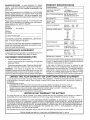
MODEL
NUMBER
917 270610
PRODUCT
SPEClfFtCAT ONS
HORSEPOWER:
15.5
GASOLINE CAPACITY
AND TYPE:
1 25 Gallons
UNLEADED REGULAR
OIL TYPE (APf-SF/SG/SH):
SAE 30 (above 32°F)
SAE 5W-30 (below 32°F)
OIL CAPACITY:
3 PINTS
SPARK PLUG:
(GAP: 030")
CHAMP!ON
RJ19LM
VALVE CLEARANCE:
INTAKE:
EXHAUST:
005" _,.007"
009" - ,011"
GROUND SPEED (MPH):
FORWARD:
1st
2nd
3rd
4th
5th
6th
REVERSE:
SERIAL
NUMBER
DATE OF PURCHASE
THE MODEL AND SERIAL NUMBERS WILL BE FOUND
ON A PLATE UNDER THE SEAT.
YOU SHOULD RECORD BOTH SERIAL NUMBER AND
DATE OF PURCHASE AND KEEP IN A SAFE PLACE
FOR FUTURE REFERENCE,
MAINTENANCE
AGREEMENT
A Sears Maintenance
Agreement
ucL Contact your nearest Sears
CUSTOMER
•
Read and observe
the safety
o
Follow a regular schedule
using your tractor..
TIRE PRESSURE:
FRONT:
REAR:
CHARGING SYSTEM:
3 AMPS BATTERY
5 AMPS HEADLIGHTS
BATTERY:
AMP/HR:
MIN CCA:
CASESIZE:
BLADE BOLT TORQUE:
27-35 FT LBS,
is available on this prodstore for details.
RESPONSIBnLIT ES
rules
10
1,3
2.1
3.1
4 0
51
1,6
14 PSI
I2 PSI
25
t90
U1R
caring for and
with a spark arrester meeting applicable local or state laws
(if any), If a spark arrester is used, it should be maintained
in effective working order by the operator.
Follow the instructions
under "Customer
Responsibilities" and "Storage" sections of this owner's manual
WARNING:
This tractor
is equipped
with an internal
combustion
engine and should not be used on or near any
unimproved
forest-covered,
brush-covered
or grass-covered land unless the engine's exhaust system is equipped
In the state of California the above is required by law
(Section 4442 of the California Public Resources Code)
Other states may have similar laws.. Federal laws apply on
federal lands. A spark arrester for the muffler is available
through your nearest Sears Authorized Service Center/
Department (See REPAIR PARTS section of this manual)
in maintaining,
o
MMEED
TWO YEAR WARRANTY
ON CRAFTSMAN
RmDING EQUIPMENT
For two (2) years from the date of purchase, if this Craftsman Riding Equipment's maintained, lubricated and tuned up according
to the instructions in the owner's manual, Sears will repair or replace, free of charge, any parts found to be defective in material or
workmanship,
This Warranty does not cover:
•
Expendable items which become worn during normal use, such as blades, spark plugs, air cleaners, belts, etc
o
Tire replacement or repair caused by punctures from outside objects, such as naiis, thorns, stumps, or glass.
°
Repairs necessary because of operator abuse, negligence, improper storage or accident or the failure to maintain the
equipment according to the instructions contained in the owner's manual,
Riding equipment used for commercial or rental purposes,,
LiMiTED 90 DAY WARRANTY
ON BATTERY
For ninety (90) days from date of purchase, if any battery included with this riding equipment proves defective in material or
workmanship and our testing determines the battery will not hold a charge, Sears will replace the battery at no charge
IN-HOME WARRANTY SERVICE ON YOUR CRAFTSMAN RIDING EQUIPMENT IS AVAILABLE AT NO-CHARGE FOR 30
DAYS FROM THE DATE OF PURCHASE. PLEASE CONTACT YOUR NEAREST SERVICE CENTER AFTER 30 DAYS FROM
THE DATE OF PURCHASE, WARRANTY SERVICE IS AVAILABLE BY TAKING YOUR CRAFTSMAN RIDING EQUIPMENT TO
YOUR NEAREST SEARS SERVICE CENTER. (IN-HOME WARRANTY SERVICE WILL STILL BE AVAILABLE AFTER 30 DAYS
FROM THE DATE OF PURCHASE BUT A STANDARD TRIP CHARGE WILL APPLY)
THIS WARRANTY APPLIES ONLY
WHILE THIS PRODUCT IS IN THE UNITED STATES.
This Warranty gives you specific legal rights, and you may also have other rights which may vary from state to state
SEARS,
ROEBUCK
AND CO.
D/817 WA, HOFFMAN
ESTATES,
IL 60179
..........u,,u,,,
u,
,,,,,,
,,,,,,
.......
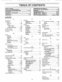
TABLE OF CONTENTS
.....................
,, ,u,
nnU,'
SAFETY RULES ................ ............................................ 2
PRODUCT SPECIFICATIONS ...................................... 3
CUSTOMER RESPONSIBILITIES ..................... 3, 17-20
WARRANTY ..................................................................
3
TRACTOR ACCESSORIES ..........................................
5
ASSEMBLY ..............................................................
7-10
OPERATION ...........................................................
11-14
11 ' = '
,
MAINTENANCE SCHEDULE ......................................
17
SERVICE AND ADJUSTMENTS ..................... ; ...... 21-26
STORAGE ....................................... _........................... 27
TROUBLESHOOTING ............................................
28-29
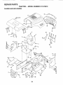
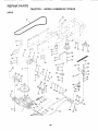
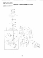
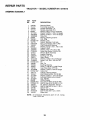
REPAIR PARTS - TRACTOR ................................. 32-47
REPAIR PARTS - ENGINE .................................... 48-55
PARTS ORDERING/SERVICE ................ BACK COVER
NDEX
E
A
Accessories .......................................
5
Adjustments:
Brake ........................................
23
Carburetor ..................................... 26
Mower
Front-To-Back ......................
22
Side-To-Side .........................
22
Throttle Control Cable ................... 26
Air Filter, Engine ..........................
t9-20
Air Screen, Engine ..........................
20
Assembly .........................................
7-10
B
Battery:
Charging ...............................
8
Cteaning ...................................
18
installation
Levets ...............................................9,18
Preparation ..................................
8
Starting with Weak Battery ............24
Storage ....................................................
27
Terminals ...........................................18
Belt:
Motion Drive
Remova!/Replacement
.................
23
Mower Belt(s)
Removal/Replacement
........... 23
Blade:
Sharpening .........................................t 8
Replacement ................................ 18
Brake Adjustment ......................................23
.....................................................
8
C
Carburetor Adjustment ........................... 26
Controls, Tractor. .................................. 12
.....................................
Customer Responsibilities ............. 17,20
Engine:
Air Fiiter ..........................................19
Air Screen
20
Cooling Fins ............................... 20
Engine Oil ............................. 14,19
Fuel Filter .........................................
20
Spark Plug(s) ..........................
20
Tractor:
Battery .............................................18
Blade .._...................................................
18
Lubrication Chart ..................... 17
Maintenance Schedule ............ 17
Tire Care ..............................
10,18, 24
Transaxle .........................................
19
Cutting Height, Mower ........................... 13
O
Electrical:
Interlocks and Relays
25
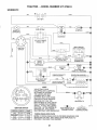
Schematic ..................................
31
Wiring Diagram .............................. 32
Engine:
Air Filter .................................... t9-20
Air Screen .................................... 20
Cooling Fins ......................................20
Oil Change .................................... 19
Oil Level ........................................... !4
Oil Type ..........................................
14, 19
Preparation ........................................13
Repair Parts .............................. 32-49
Starting ............................................ I5
Storage ........................................
27
.................
F
[
Filter:
Air Filter..........................................
Fuel ......................................
Fuel:
Type .............................................
Storage ........................................
Fuse ....................................................
19
20
15
27
25
H
Hood Removal/installation
................... 25
L
Leveling Mower Deck .......................... 22
Lubrication:
Chart .............................................. t7
Engine ............................................. 19
M
Maintenance Schedule .....................
22
Mower:
Adjustment, Front-to-Back ..............22
Adjustment, Side-to-Side ............ 22
Blade Replacement ..................... 18
Blade Sharpening ......................... 18
Cutting Height .............................. 13
Installation ..........................................21
Operation ..................................... 14
Removal ........................................... 21
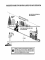
Mowing Tips ..............................................15
Muffler ..................................................
20
Spark Arrester. ........................... 3,42
Oil:
Cold Weather Conditions ........ 15,19
Engine .........................................
19
Storage ............................................ 27
Operation ....................................
1O-14
Operating Mower ................................. 13
Options:
Accessories ........................................ 5
Spark Arrester ................................ 3
P
Parking Brake ................................... 12,13
Parts Bag ........................................................
6
Parts, Replacement/Repair
...............32-49
Product Specifications ............................... 3
R
Repair Parts ...................................
32-49
S
Safety Rules ..................................................
2
Seat
...................................................................
8
Service and Adjustments ................ 21-26
Carburetor
................................
26
Fuse ...........................................................
2,5
Hood Removalftnstallation ........... 25
ivtotion Drive Belt
RemovaYReplacement
........... 23
Mower Bell(s)
Removal/Replacement
...............23
Mower Adjustment
Front-to-Back ........................... 22
Side4o-Side ............................... 22
Mower Removal/Installation ......... 21
Tire Care ...................................t0,18,24
Slope Guide Sheet ...................
_................. 57
Spark Plug(s)
20
Specifications ........................................
3
Starting the Engine .......................... 14-15
Steering Wheel ................................. 7, 24
Stopping the Tractor ............................... t3
Storage .................................................... 27
..................................................
T
Throttle Control Cable Adjustment .........26
Tires ............................................ 10, 18, 24
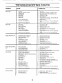
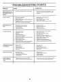
Trouble Shooting Chart .....................28-29
Transaxle
19
.................................................
W
Warranty .................................................. 3
Wiring Diagram .................................................
32
Wiring Schematic .................................. 31
ACCESSORIES
,11111
AN
ATTACH
u ,i,,111,,,11,1,,,
i,r,,
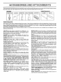
These accessories and attachments were available through most Sears retail outlets and service centers when the tractor was purchased.
Most Sears stores can order these items for you when you provide the model number of your tractor
ENGINE
SPARK PLUG
MAINTENANCE
GAS CAN
ENGINE OIL
FUEL STABILIZER
AIR FILTER
BLADES
BELTS
PERFORMANCE
Sears offers a wide variety of attachments that fit your tractor
you This list was current at the time of publication; however,
may be made in these attachments, or some may no longer
accessories
and attachments
that are available for your
Most of these attachments
attaching and detaching.
Many of these are listed below with brief explanations of how they ean help
it may change in future years - more attachments may be added, changes
be available or fit your model Contact your nearest Sears store for the
tractor.
do not require additional hitches or conversion kits (those that do are indicated)
AERATOR promotes deep root growth for a healthy lawn Ta _
pered 2 5-inch steel spikes mounted on 10-inch diameter discs
puncture holes in soil at close intervals to let moisture soak in
Steel weight tray for increased penetration
BAGGER lets you collect
grass clippings and leaves for a
healthier, nearer looking fawn Two Permanex containers hold
30-gallon plastic bags.
BUMPER protects front end of tractor from damage
CARTS make hauling easy
Variety of sizes available, pEus
accessories such as side panel kits, tool caddy, cart cover,
protective mat and dolly.
CORING AERATOR takes small plugs out of soil to allow moisture and nutrients to reach grass roots. 36-inch swath
24
hardened steel coring tips 150 Ib. capacity weight tray
EASY OIL DRAIN VALVE makes oil changes easier, faster
FRONT NOSE ROLLER canters in front of mower deck to reduce
chances of "scalping" on uneven terrain.
GANG HITCH lets you tow 2 or 3 pull-behind attachments at once,
such as sweepers, dethatchers, aerators (not for use with roIlers,
carts or other heavy attachments)
GAUGE WHEELS on both sides of the mower deck reduce
chances of"scalping" on uneven terrain. For mower decks not so
equipped.
MULCH RAKE/DETHATCHER
loosens soil and flips thatch and
matted leaves to lawn sudace for easy pickup Twenty spring line
teeth Useful to prepare bare areas fo rseeding. Available for front
or rear mounting.
HIGH PERFORMANCE
REEL-ACTION
SPRING TINE DETHATCHER covers 36-inch wide path and
tosses thatch into large hopper Mounts behind tractor
MULCHING CLOSE-OUT PLATE KIT, once installed, lets you
mulch, discharge or bag clippings (bagger optional) without
changing blades For modeis not equipped as 3-in-1 Convertible
mowers
See "MOWER" in the Repair Parts section of this
manual
RAMP TOPS AND FEET let you load and un!oad tractor from a
pickup truck
Use with 2 x 8 or 2 x 10 lumber.
ROLLER for smoother lawn surface.
36-inch wide, 18-inch
diameter water-tight drum holds up to 390 Ibs. of weight Rounded
edges prevent harm to turf. Adjustable scraper automatically
cleans drum.
and are designed for easy
SNOW BLADE for snow removal only. t4-1nch high, 48-inch wide
blade clears 42-inch path when angled left or righL Raises, lowers
with side lever Adjustable skids; replaceable, reversible scraper
bar (Use with tire chains and wheel weights and/or rear drawbar
weight )
SNOWTHROWER has 40-inch swath Drum-type auger handles
powdery and wet/heavy snow
Mounts easily with simple pin
arrangement Discharge chute adjusts from tractor seat 6-inch
diameter spout discharges snow 10 to 50 feet. Lift controlled at
tractor seat. (Use with chains and wheel weights and!or rear
drawbar weight .)
SPRAYERS use 12-volt DC electric motor that connecls to the
tractor battery or other 12-volt source
includes booms for
automatic spraying and hand held wand for spot spraying Wand
has adjustable spray pattern
For app{ying herbicides, insecticides, fungicides and liquid fertilizers.
SPREADER/SEEDERS
make seeding, fedilizing, and weed killing easy, Broadcast spreaders are also useful for granular deicers and sand
SWEEPERS let you coltect grass clippings and leaves,
TILLER has 5 hp engine and 36-inch swath to prepare seed beds,
cultivate and compost garden residue Tiller has its own built-in
lift and depth :ontrol system and does NOT require a sleeve hitch
Fits any law_ yard orgarden tractor, Simply hook up to the tractor
drawbar and go!
Optional
accessories
convert unit for
dethatching, aerating, hilling...without tools.
TIRE CHAINS are heavy duty; closely spaced extra-large cross
links give smooth ride, outstanding traction
TRACTOR CAB has heavy duty vinyl fabric over tubular steel
frame, ABS plastic top; clear plastic windshield offers 360 degree
visibility Hinged metal doors with catch. Keeps operator warm
and dry Remove vinyl sides and windshields for use as sun
protector in summer
Optional accessories
include:
tinted/
tempered solid safety glass windshield with hand operated wiper;
12-volt amber caution light for mounting on cab top.
VACS for powerful coflection of heavy grass clippings and leaves.
Optional wand attachment to pick up debris in hard-to-reach
places. VAC/CHIPPER includes a chipper-shredder
WEIGHT BRACKET for drawbar for snow removal applications
Uses (1) 55 Ib weight
WHEEL WEIGHTS for rear wheels provide needed traction for
snow removal or dozing heavy materials.
.......
i
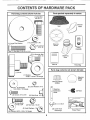
OF HARDWARE
PAC
Parts packed
(1) La[ge Flat Washer
separately
in carton
Mulcher
Plate
Seat
©
(1) Lockwashe_
,,11
.......
3/8
Steering
Wheel
Locknut
5/16-18
Video
Cassette
x 1-1/4@(t)
(1) Shoulder Bolt
5/16-18
Steering
Boot
Manual
Pa_s Bag
i
Parts bag contents
not shown
full size
(1) Knob
,
,
Steering
Wheel
Insert
Steering Wheel
Adapter
Steering
Extension
Shaft
(2) Keys
O
(2) Latch Hook
Assemblys
6
Slope Sheet
,,11
i,, ,,,,,,11,1
......
ii
, i,
,, ,i ........
'
i
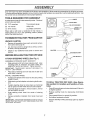
ASSEMBLY
...............
i,,i
Your new tractor has been assembled at the factory with exception of those parts left unassembied for shipping purposes..
To ensure safe and proper operation of your tractor all parts and hardware you assemble must be tightened securely Use
the correct tools as necessary to insure proper tightness.
TOOLS REQURRED FOR ASSEMBLY
A socket wrench set will make assembly easier_. Standard
wrench sizes are listed,
(2) 7/16" wrenches
Tire pressure gauge
(2) 1/2" wrench
Utility knife
(1) 9/16" wrench
(I) phillips screwdriver
When right or left hand is mentioned in this manual, it
means when you are in the operating position (seated
behind the steering wheel)..
TO REMOVE TRACTOR
UNPACK
FROM CARTON
_-,_-_
*'_'-"
CARTON
=
Remove all accessible loose parts and parts cartons
from carton (See page 6)..
o
Cut, from top to bottom, along lines on all four corners
of carton, and lay panels flat.
-
STEERING
WHEEL
STEERING
BOOT,
ADAPTER
Check for any additional loose parts or cartons and
remove.
BEFORE ROLLING TRACTOR OFF SKED
_
_,_
ATTACH
STEERING
WHEEL
EXTENSION
I _
SHAFT
5116 BEX BOLT
(See Fig. 1)
ASSEMBLE EXTENSION SHAFT AND BOOT
•
Slide extension shaft onto lower steering shaft. Align
mounting holes in extension and lower shafts and
install 5/16 hex bolt and Iocknut. Tighten securely
IMPORTANT: TIGHTEN BOLT AND NUT SECURELY TO
18-22 FT. LBS TORQUE
5/16 LOCKNUT
Place tabs of steering boot over tab slots in dash and
push down to secure
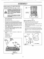
INSTALL STEERING WHEEL
"7 - -_
"_"
/t
;
o
LOWER
STEERING
SHAFT
"
_,
_ / /
_ _ _
I __
"" " _-,_ _'_P
°
Position front wheels of the tractor so they are pointing
straight forward.
•
Slide steering wheel adapter onto steering shaft extension,
°
Position steering wheel so cross bars are horizontal
(left to right) and slide inside boot and onto adapter
o
Assemble large flat washer, 3/8 lock washer, 3/8 hex
bolt and tighten securely.
o
Press iift lever plunger and raise attachment lift lever to
its highest position
=
Snap steering wheel insert into center of steering
wheel
,,
Remove protective materials from tractor hood and
grill..
IMPORTANT: CHECK FOR AND REMOVE ANY STAPLES
iN SKID THAT MAY PUNCTURETIRES WHERE TRACTOR
IS TO ROLL OFF SKID
o
o
Release parking brake by depressing clutch/brake
pedal..
Place gearshift lever in neutral (N) position_
Roll tractor backwards off skid°
o
FIG. 1
TO ROLL TRACTOR OFF SKID (See Operation section for location and function of controls)
-
Remove banding holding discharge guard up against
tractor.
,
, ......
i,iiii
ASSEMBLY
HOW TO SET UP YOUR TRACTOR
CONNECT
BATTERY
SEAT
PAN
(See Figs. 2 and 3)
CAUTION: Do not short battery terminals by allowing a wrench or any other
object to contact both terminals at the
same time. Before connecting battery,
remove metal bracelets, wristwatch
bands, Hngs, etc.
BOXDOOR
Positive terminal must be connected
first to prevent sparking from accidental grounding.
=
Remove cardboard packing from seat pan and tiff seat
pan to raised position,,
.
Open battery box door
°
Remove terminal protective caps and discard,
.
If this battery is put into service after month and year
indicated on label (label located between terminals)
charge battery for minimum of one hour at 6-10 amps.
o
o
o
FIGo 3
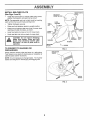
INSTALL
Adjust seat before tightening ._djustment knob,
First connect RED battery cable to positive (+) terminal
with hex bolt, flat washer, lock washer and hex nut as
shown,, Tighten securely,,
o
Remove cardboard pactdng on seat pan.
o
Place seat on sea[ pan and assemble shoulder bolt.
Tighten shoulder bolt securely.
Q
Assemble adjustment
Do not tighten,
f
Connect BLACK grounding cable to negative (-) termina] with remaining hex bolt, flat washer, lock washer
and hex nuL Tighten securely
e
Slide seat until a comfortable position is reached which
allows you to press clutch/brake pedal all the way
down,
=
Get off seat without moving its adjusted position.
Close battery box door
Inspection for' secure connections
ware).
°
Inspection for corrosion
o
.
Testing battery.
Jumping (if required).
°
Periodic charging ,.
POSITIVE
(RED} CABLE
knob and flat washer Ioosely.
Lower seat into operating position and sit on seat,.
Open battery box door for:
-
SEAT (See Fig, 4)
(to tighten hard-
Raise seat and tighten adjustment knob securely
SEAT PAN
SEAT
SHOULDER
BOLT
DISCARD
TERMINAL
PROTECTIVE
CAPS
HEX
NUT
LOCK
WASHER
FLAT WASHER
FLAT
ADJUSTMENT
KNOB
WASHER
FIG. 4
HE×
BOLT
NEGATIVE
_(BLACK)CABLE
FIG. 2
8
INSTALL MULCHER
(See Figs. 5 and 6)
o
PLATE
InstalI two latch hooks to mulcher plate using screw,
washer, lock washer, and weld nut as shown.
NOTE: Pre-assembte weld nut to latch hook by inserting
weld nut from the top with hook pointing down..
LOCK
o
Tighten hardware securely.
WELD
,
Raise and hold deflector shield in upright posffion..
NUT
=
•
Place front of mulcher plate over front of mower deck
opening and slide into place, as shown.
Hook front latch into hole on front of mower deck.
•
Hook rear latch into hole on back of mower deck
.......
DOWN
WELD NUT
FROM THE TOP
WASHER
_.
SCREW
HOOK
LATCH
HOOK
ii
guard from mower. Raise and hold
CAUTION:
not remove
discharge
guard whenDoattaching
mulcher
plate
and allow it to rest on plate while in
operation.
LOCK
WASHER
WASHER
WELD
NUT
PLATE
TO CONVERT
DISCHARGING
TO BAGGING
OR
FIG. 5
DEFLECTOR
SHIELD
Simply remove muicher plate and store in a safe place.
Your mower is now ready for discharging or installation of
optional grass catcher accessory,
J
NOTE: It is not necessary to change blades, The mulcher
blades are designed for discharging and bagging also,
LATCH
HOOKS
FIG. 6
9
, ,i,1,,,111,,,
i,,,,,i
,
ii
i,iii
i, ,,i,i1,,
i,,11.,_1,,,.,_,1111,11,11,
,i
,
ii
r
]
ASSEMBLY
I
CHECK
TIRE
,/CHECKLIS
PRESSURE
The tires on you r tractor were ovednf!ated at the factory for
shipping purposes_ Correct tire pressure is important for
bgst cutting performance.
,
PLEASE REVIEW THE FOLLOWING
DECK LEVELNESS
For best cutting results, mower housing should be properly
leveled
See "TO LEVEL MOWER HOUSING" in the
Service and Adjustments section of this manual.
CHECK
BELTS
FOR
PROPER
POSITION
OF ALL
See the figures that are shown for replacing motion and
mower blade drive belts in the Service and Adjustments
section of this manual. Verify that the belts are routed
correctty_
CHECK
T
BEFORE YOU OPERATE AND ENJOY YOUR NEW
TRACTOR, WE WISH TO ASSURE THAT YOU RECEIVE
THE BEST PERFORMANCE AND SATISFACTION FROM
THIS QUALITY PRODUCT
Reduce tire pressure to PSi shown in "PRODUCT
SPECIFICATIONS" on page 3 of this manual.
CHECK
!1
/
All assembly instructions
#'
No remaining loose parts in carton.
v"
Battery is properly prepared and charged_
1 hour at 6 amps)o
•/
Seat is adjusted comfortably and tightened securely.
_/
Al! tires are properly inflated. (For shipping purposes,
the tires were overinflated at the factory).
,/
Be sure mower deck is properly leveled side-to-side/
front-to-{ear for best cutting results. (Tires must be
properly inflated for leveling).
,/
Check mower and drive belts. Be sure they are routed
properly around pulleys and inside all belt keepers_
v"
Check wiring. See that all connections are still secure
and wires are properly clamped.
BRAKE SYSTEM
After you learn how to operate your tractor, check to see
that the brake is properly adjusted. See "TO ADJUST
BRAKE" in the Service and Adjustments section of this
manual.
CHECKLIST'.
have been completed.
(Minimum
WHILE LEA RNING HOW TO USE YOUR TRACTOR, PAY
f EXTRA A TTENTtON TO THE FOLL OWING IMPORTANT
ITEMS:
/
Engine oil is at proper leveI
/
Fuel tank is filled with fresh, clean, regular unleaded
gasoline.
_" Become familiar with all controls - their location and
function= Operate them before you start the engine.
J
10
Be sure brake system is in safe operating condition.
ii,
i , u,,,,n,,,,ll ...............................
,.....
, ,,, u,,,,,,,i
,
,i ,q
OPERATION
ii
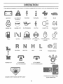
These symbols
,hi,
n,,
may appear
lu,u,
i,,,i
, ,
on your tractor or in literature supplied with the product.
Learn and understand
_ .....
their meaning_
BATTERY
CAUTION OR
WARNING
REVERSE
FORWARD
FAST
SLOW
ENGINE ON
ENGINE OFF
OIL PRESSURE
CLUTCH
LIGHTS ON
OVER TEMP
LIGHT
MOWER HEIGHT
DIFFERENTIAL
LOCK
PARKING BRAKE
LOCKED
\
FUEL
CHOKE
REVERSE
NEUTRAL
HIGH
LOW
UNLOCKED
PARKING BRAKE
÷
MOWER LIFT
ATTACHMENT
CLUTCH ENGAGED
ATTACHMENT
CLUTCH DISENGAGED
IGNITION
HYDROSTATIC
DANGER, KEEP HANDS AND FEET AWAY
FREE WHEEL
(Hydro Models only)
11
OPERATION
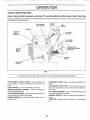
KNOW YOUR TRACTOR
READ THIS OWNER'S
MANUAL
AND SAFETY
RULES
BEFORE
OPERATING
YOUR TRACTOR
Compare the illustrations with your tractor to familiarize yourseff with the locations of various controis and adj ustments
this manual for future reference°
IGNITION
SWITCH
Save
LIGHT
SWITCH
LIF1 LEVER
PLUNGER
ATTACHMENT
LIFT LEVER
o
CLUTCH{
BRAKE
PEDAL
MOWER DECK
HEIGHT ADJUSTMENT
POSITIONS
PARKING
BRAKE
GEARSHIFT
LEVER
"_
FIG. 7
Our tractors conform to the safety standards of the American National Standards Institute,,
ATTACHMENT CLUTCH LEVER: Used to engage the
mower blades, or other attachments mounted to your
tractor,
GEARSHIFT LEVER: Selects the speed and direction of
tractor°
ATTACHMENT LIFT LEVER: Used to raise, lower, and
adjust the mower deck or other attachments mounted to
your tractor',.
LIFT LEVER PLUNGER: Used to release attachment lift
lever' when changing its position
LIGHT SWITCH: Turns the headlights on and offl
THROTTLE/CHOKE
CONTROL:
Used for starting and
controlling engine speed,
CLUTCHIBRAKE PEDAL: Used for declutching and braking the tractor and starting the engine,
PARKING BRAKE:
brake position_
Locks clutch/brake
IGNITION SWITCH: Used for starting and stopping the
engine,,
AMMETER: indicates battery charging (+) or discharging
pedal into the
12
i,
i
OPERATION
,,,i, ,,,,i,,,i,
,,i
..................
i,i
.......
i
i ,,,i,
i,iii,
,
.....................
The operation of any tractor can result in foreign objects thrown into the eyes, which
can result in severe eye damage. Always wear safety glasses or eye shields while
operating your tractor or performing any adjustments or repairs. We recommend a wide
vision safety mask over the spectacles or standard safety glasses.
,
, i,iii .....
i,,i,ir,l,,i,,i
...........
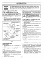
HOW TO USE YOUR TRACTOR
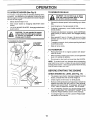
TO SET PARKING
BRAKE
(See Fig. 8)
Your tractor is equipped with an operator presence sensing
switch. When engine is running, any attempt by the
operator to leave the seat without first setting the parking
brake will shut off the engine.
= Depress clutch/brake pedal into full "BRAKE" position
and hold
=
ing the operator's
position;
grass catcher, etc.
TO USE THROTTLE
IGNITION
Operating engine at less than full throttle reduces the
battery charging rate
o
Full throttle offers the best bagging and mower performance
AND BACKWARD
The direction and speed of movement
gearshift lever..
* PARKING BRAKE
"ENGAGED"
POSITION
PARKtNC
"DISENGAGED"
POSITION
o
Start tractor with clutch!brake pedal depressed and
gearshift lever in neutral (N) position
=
Move gearshift lever to desired
TO ADJUST MOWER
(See Fig. 8)
CLUTCH/BRAKE
PEDAL
"DRIVE" POSITION
position,
CUTTING
The position of the attachment
cutting height,.
•
FIG. 8
HEIIGHT
lift lever determines
the
Grasp lift lever
Press plunger with thumb and move lever to desired
position
(See Fig. 8)
MOWER BLADES =
Move attachment clutch lever to "DISENGAGED"
sition.
GROUND DRIVE -
is controlled by the
= Slowly release clutch!brake pedal to start movement
IMPORTANT: BRING TRACTOR TOA COMPLETE STOP
BEFORE SHIFTING OR CHANGING GEARS. FAILURE
TO DO SO WILL SHORTEN THE USEFUL LIFE OF YOUR
TRANSAXLE
GEARSHIFT
LEVER
STOPPING
(See Fig. 8)
=
TO MOVE FORWARD
(See Fig. 8)
_,_GAGED"
POSITION
POSITION
CONTROL
to empty
Always operate engine at full throttle..
ATTACHMENT CLUTGH LEVER
"ENGAGED"
POSITION
\,
"_ .............
CAUTIdN;Aiwaystop ractorcompletely;
as described above, before leav-
Place parking brake lever in "ENGAGED" position and
refease pressure from clutch/brake pedaL Pedalshoutd
remain in "BRAKE" position, Make sure parking brake
will hold tractor secure,.
THROTTLFJCHOKE
CONTROL LEVER
' ...........
NOTE: Under cedain conditions when tractor is standing
idle with the engine running, hot engine exhaust gases may
cause "browning" of grass. To eliminate this possibility,
always stop engine when stopping tractor on grass areas_
The cutting height range is approximately 1_1/2 to 4". The
heights are measured from the ground to the blade tip with
the engine not running These heights are approximate
and may vary depending upon soil conditions, height of
grass and types of grass being mowed,
po-
o Depress clutch/brake pedal into full "BRAKE" position,
Move gearshift lever to neutral (N) position
ENGINE •
Move throttle control to slow position.,
NOTE: Failure to move throttle control to slow position and
allowing engine to idle before stopping may cause engine
to "backfire"
.
Turn ignition key to "OFF" position and remove key.
Always remove key when leaving tractor to prevent
unauthorized use,
•
Never use choke to stop engine
13
o
The average fawn should be cut to approximately 2-1/2
inches during the cool season and to over 3 inches
during hot months
For healthier and better looking
lawns, mow often and after moderate growth.
o
For best cutting performance, grass over 6 inches in
height should be mowed twice
Make the first cut
relatively high; the second to desired height
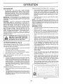
TO OPERATE
MOWER
TO OPERATE
(See Fig. 9)
Your tractor is equipped with an operator presence sensing switch_ Any attempt by the operator to leave the seat
with the engine running and the attachment clutch engaged
will shut off the engine_
=
Select desired height of cut.
=
Start mower blades by engaging attachment
control
•
TO STOP MOWER BLADES - disengage attachment
clutch control.
,_
I _
I _
"ENGAGED"
POSITION
ATTACHMENT
LIFT LEVER
HIGH POSITION
|
I
Choose the slowest speed before starting up Dr down
hNIs_
=
Avoid stopping or changing speed on hills°
•
If slowing is necessary, move throttle control lever to
slower position.
,
If stopping is absolutely necessary, push clutch/brake
pedal quickly to brake position and engage parking
brake
°
Move gearshift lever to 1st gear. Be sure you have
allowed room for tractor to roll slightly as you resta_
movement.
•
Torestart movement, slowly release parking brake and
clutch/brake pedal.
°
Make all turns slowly
,, ,,,,,
ATTACHMENT CLUTCH LEVER
"DISENGAGED"
POSITION
CAUTION:
DO not drive up or d0wn
hills with slopes greater than 15 ° and
do not drive across any slope.
•
clutch
CAUTION: Do not operate the mower
without either the entire grass catcher,
on mowers so equipped, or the discharge guard in place,
ON HILLS
TO TRANSPORT
r
,
Raise attachment
merit lift control
•
When pushing or towing your tractor, be sure gearshift
lever is in neutral (N) position°
Do not push or tow tractor at more than five (5) MPH.
°
lift to highest position with attach-
NOTE: To protect hood from damage when transporting
your' tractor on a truck or a trailer, be sure hood is closed
and secured to tractor'.. Use an appropriate means of tyirig
hood to tractor (rope, cord, etc.).
BEFORE STARTING
CHECK ENGINE
_t
o
DISCHARGE
GUARD
FIG. 9
14
THE ENGINE
OIL LEVEL (See Fig. 14)
The engine in your tractor' has been shipped, from the
factory, already filled with summer" we!ght oito i
Check engine oil with tractor on level ground,
•
Remove oil fill cap/dipstick and wipe clean, reinsert the
dipstick and screw cap tight, wait for a few seconds,
remove and read oil level. If necessary, add oil until
"FULL" mark on dipstick is reached. Do not overfill.
,
For cold weather operation you should change oil for
easier starting (See "OIL VISCOSITY CHART" in the
Customer Responsibilities section of this manual),
•
To change engine oil, see the Customer Responsibilities section in this manual
OPERATUON
ADD GASOLINE
COLD WEATHER STARTING
o
o
When engine starts, allow engine to run with the throttle
control in the choke position until the engine runs
roughly, then move throttle control to fast position This
may require an engine warm-up period from several
seconds to several minutes, depending on the temperature.
o
The attachments can also be used during the engine
warm-up period..
Fill fuel tank. Use fresh, clean, regular unleaded
gasoline with a minimum of 87 octane_ (Use of leaded
gasoline will increase carbon and lead oxide deposits
and reduce valve life).. Do not mix oil with gasoline.
Purchase fuel in quantities that can be used within 30
days to assure fuel freshness..
IMPORTANT: WHEN OPERATING IN TEMPERATURES
BELOW 32°F(0°C), USE FRESH, CLEAN WINTER GRADE
GASOLINE TO HELP INSURE GOOD COLD WEATHER
STARTING.
NOTE: if at a high altitude (above 3000 feet) or in cold
temperatures (below 32 F) the carburetor fuel mixture may
need to be adjusted for best engine performance. See "TO
ADJUST CARBURETOR" in the Service and Adjustments
section of this manual
WARNING:
Experience indicates that alcohol blended
fuels (called gasohol or using ethanol or methanol) can
attract moisture which leads to separation and formation of
acids during storage., Acidic gas can damage the fuel
system of an engine while in storage
To avoid engine
problems, the fuel system should be emptied before storage of 30 days or longer.1 Drain the gas tank, start the
engine and let it run until the fuel lines and carburetor are
empty, Use fresh fuel next season,, See Storage Instructions for additional information.
Never use .engine or
carburetor cleaner products in the fuel tank or permanent
damage may occur.
, i i
,,,
,,
,, i, i1,_,,_,_,,
MOWtNG TiPS
TO START
ENGINE
i ........
i, i,u,,i
Sit on seat in operating position, depress clutch/brake
pedal and set parking brake,
.
-
Place gear shift lever in neutral (N) position
Move attachment clutch to "DISENGAGED" position
=
Move throttle controt to choke position,
Note: Before starting, read the warm and cold starting
procedures below.,
°
°
o
Mower should be properly leveled for best mowing
performance See "TO LEVEL MOWER HOUSING" in
the Service and Adjustments section of this manual
Tile left hand side of mower should be used for trimming
o
Drive so that clippings are discharged onto the area
that has been cut. Have the cut area to the right of the
machine. This will result in a more even distribution of
clippings and more uniform cutting.
o
When mowing large areas, start by turning to the right
so that clippings will discharge away from shrubs,
fences, driveways, etc After one or two rounds, mow
in the opposite direction making left hand turns until
finished (See Fig t0)
o
tf grass is extremely tall, it should be mowed twice to
reduce load and possible fire hazard from dried clippings.. Make first cut relatively high; the second to the
desired height
o
Do not mow grass when it is wet.. Wet grass will plug
mower and leave undesirable clumps. Allow grass to
dry before mowing.
.
Always 3perate engine at full throttle when mowing to
assure better mowing performance and proper discharge of material Regulate ground speed by selecting a low enough gear to give the mower cutting
performance as well as the quality of cut desired
o
When operating attachments, select a ground speed
that will suit the terrain and give best performance of
the attachment being used.
(See Fig. 8)
.
Insert key into ignition and turn key clockwise to"START"
position and release key as soon as engine starts. Do
not run starter continuously for more than fifteen seconds per minute
tf the engine does not start after
several attempts, move throttle control to fast position,
wait a few minutes and try again, If engine still does not
start, move the throttle control back to the choke
position and retry_
WARM WEATHER
Tire chains cannot be used when the mower housing is
attached to tractor
o
When starting the engine for the first time or if the engine
has run out of fuel, it will take extra cranking time to move
fuel from the tank to the engine
.
o
,,
CAUTION:
Fill to bottom of gas tank
filler neck. Do not overfill. Wipe off any
spilled oil or fuel. Do not store, spill or
use gasoline near an open flame.
, ,
( 50'* F and below)
f
STARTING (50 ° F and above)
When engine starts, move the throttle control to the fast
position.,
The attachments and ground drive can now be used. If
the engine does not accept the load, restart the engine
and allow it to warm up for one minute using the choke
as described above
J
FIG. 10
15
=.............
i
ii,
i
I_I,rI,,r=HU,U,I,,=,
!
=
OPERATIO
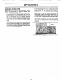
MULCHING
MOWING
TIPS
o
For best results, adjust the mowercutting height so that
the mower cuts off only the top one-third of the grass
blades (See Fig° 11 ). For extremely heavy mulching,
reduce your width of cut on each pass and mow slowly°
=
Certain types of grass and grass conditions may require that an area be mulched a second time to
completely hide the clippings. When doing a second
cut, mow across or perpendicular to the first cut path.
o
Change your cutting pattern from week to week, Mow
north to south one week then change to east to west the
next week, This wilt help prevent matting and graining
of the lawn.
IMPORTANT:
FOR BEST PERFORMANCE,
KEEP
MOWER HOUSING FREE OF BUILT-UP GRASS AND
TRASH CLEAN AFTER EACHUSE_
=
o
The special mulching blade will recut the grass clippings many times and reduce them in size so that as
they fall onto the lawn they will dlsperse into the grass
and not be noticed_ Also, the mulched grass will
biodegrade quickly to provide nutrients for the lawn.
Always mufch with your highest engine (blade) speed
as this will provide the best recutting action of the
blade&
Avoid cutting your lawn when it is wet, Wet grass tends
to form clumps and interferes with the mulching action.
The best time to mow your fawn is the early afternoon_
At this time the grass has dried and the newly cut area
will not be exposed to the direct sun_
MAX 1/3
lit
FIG. !1
L
16
i
i,=l,,U
,,
nn ,,n .......
OUSTOME
,_
ii ....
,.....
,,
u,,,,.
ESPONSIB L qrBES
......................
,lu ...........
_
n
i
'
iii
' ........................
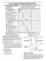
AS YOU COMPLETE
REGULAR SERVlCE ...
J__4__SERV!CEDATES
Check Brake Operation
Check Tire Pressure
6#4
f
Check for Loose Fasteners
a
Sharpen/Replace Mower Blades
_
Lubrication Chart
_
...........
]
[
T ,C heck Battery LeveVRecharge
0
Clean Battery and Terminals
a
CheckTransaxle Cooling
Adjust Blade Belt(s) Tension
_5
.......
Adjust Motion Drive Belt(s) Tension
J
Check Engine Oil Level
Change
E
Clean
Engine
Oil
Air Filter
.......
, _#'2
N
Clean,Air Screen
G ! Inspect Muffler/Spark Arrester
[
t
,
,
Replace Oil Filter (if equipped)
N cleaoEng oe
Coo ing
Fins
Replace Spark Plug
Replace
Air Filter Paper
Reptace Fuel Filter
..............
12 3 4 -
Cartridge
,,,,
,,
5 - It equipped wilt_ adiustable syslem
6 - Not requfed il equipped with maintenance-free
battery
7 - Tighten float axle pivot bolt to 35 ft-Ibs maximum
Change more often when operating under a heavy toad or in high ambient temperatures
Service more often when operating in dirty or dusty conditions
tf equipped with o{1_ilter. change oit eve_ 50 hours
Replace blades more often when mewing in sandy soil
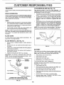
GENERAL
DO eel
overlighten
LUBRICATION
RECOMMENDATIONS
CHART
(_)SPINDI
The warranty on this tractor does not cover items that have
been subjected to operator abuse or negligence
To
receive full value from the warranty, operator must maintain
tractor as instructed in this manual.
_)
(_) FRON]
SEARING
Some adjustments will need to be made periodically to
properly maintain your tractor°
_ FRONT WHEEL (_)
BEARING ZERK
ZERK
All adjustments in the Service and Adjustments section of
this manual should be checked at least once each season.
o
®
Once a year you should replace the spark pIug, clean
or replace air filter, and check blades and belts for
wear.. A new spark plug and clean air filter assure
proper air-fuel mixture and help your engine run better
and last longer..
BEFORE
(_ ATTACHMENT
CLUTCH
PIVOT(S)
_
®
EACH USE
=
Check engine oil level
=
Check brake operation
o
.
Check tire pressure.
Check for loose fasteners..
PIVOTS
(_SAE
30 OR 10W30 MOTOR OIL
(_)GENERAL
(_)REFER
17
PURPOSE GREASE
TO CUSTOMER
RESPONSIBILITIES
"ENGINE"
SECTION
IMPORTANT;
DO NOT OtL OR GREASE THE PIVOT POINTS
WHICH HAVE SPECIAL NYLON BEARINGS
VISCOUS
LUBRICANTS WILL ATTRACT
DUST AND DIRT THAT WILL SHORTEN
THE LIFE OF THE SELF-LUBRICATING
BEARINGS.
_F YOU
FEEL THEY MUST BE LUBRICATED,
USE ONLY A DRY. POWDERED GRAPHITE
TYPE LUBRICANT
SPARINGLY
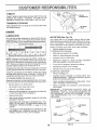
TO SHARPEN BLADE (See Fig. 13)
Care should be taken to keep the blade balanced, An
unbalanced blade will cause excessive vibration and eventuat damage to mower and engine.
BRAKE
OPERATION
If tractor requires more than six (6) feet stopping distance
at high speed in highest gear, then brake must be adjusted.
(See "TO ADJUST BRAKE" in the Service and Adjustments section of this manual).
TIRES
o
Maintain proper air pressure in all tires (See "PRODUCT SPECIFICATIONS" on page 3 of this manual).
•
Keep tires free of gasoline, oil, or' insect control chemicals which can harm rubber.
o
Avoid stumps, stones, deep ruts, sharp objects and
other hazards that may cause tire damage,
•
The blade can be sharpened with a file or on a grinding
wheel. Do not attempt to sharpen while on the mower.
o
To check blade balance, you will need a 5/8" diameter
steel bolt, pin, or a cone balancer. (When using a cone
balancer, follow the instructions supplied with balancer).
o
Slide blade on to an unt hreaded portion of the steel bolt
or' pin and hold the bolt or pin parallel with the ground,
If blade is balanced, it should remain in ahorizontal
position. If either end of the blade moves downward,
sharpen the heavy end until the blade is balanced°
NOTE: Do not use a nail for balancing blade. The lobes of
the center hole may appear to be centered, but are not.
NOTE: To seal tire punctures and prevent fiat tires due to
stow leaks, tire sealant may be purchased from your' local
parts dealer. Tire sealant also prevents tire dry rot and
corrosion°
BLADE
CENTER
HOLE
CARE
For best results mower btades must be kept sharp. Replace bent or damaged blades,
BLADE
REMOVAL
(See Fig. 12)
o
Raise mower to highest position to allow access to
blades..
•
Remove hex bolt, lock washer' and flat washer securing blade.
.
Install new or resharpened blade with trailing edge up
towards deck as shown.
=
Reassemble hex bolt, lock washer and flat washer in
exact order as shown.
FIG. 13
BATTERY
Your tractor has a battery charging system which is sufficient for normal use. However, periodic charging of the
battery with an automotive charger will extend its life,
° Tighten bolt securely (27-35 FL Lbs. torque).
IMPORTANT: BLADE BOLT IS GRADE 8 HEATTREATED.
NOTE: We do not recommend sharpening blade - but if
rou do, be sure the blade is balanced.
BLADE
\
BLADE
518" BOLT
OR PiN
ASSEMBLY
,_
Keep battery and terminals clean.
=
Keep battery bolts tight.
•
Keep small vent holes open.
=
Recharge at 6-10 amperes for 1 hour.
TO CLEAN BATTERY AND TERMINALS
Corrosion and dirt on the battery and terminals can cause
the battery to "leak" power°
MANDREL
TRAILING
EDGE UP
LOCK WASHER
"HEX
•
BOLT (GRADE S)*
*A GRADE 8 HEAT TREATED BOLT CAN BE
IDENTIFIED BY SIX LINES ON THE BOLT HEAD,
FIG. 12
18
-
Open battery box door.
°
Disconnect BLACK battery cable first then RED battery cable and remove battery from tractor.
=
Rinse the battery with plain water and dry.
o
Clean terminals and battery cable ends with wire brush
until bright.
°
Coat terminals with grease or petroleum jelly.
•
Reinstall battery (See "CONNECT
Assembly section of this manual).
BATTERY"
in the
, i,nll
.....
i
CUSTOMER
,,
i,nn, ,UUl
in,u
,
u,,.,,=,l .............
i,,
RESPONSDBR
'
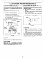
V-BELTS
_ FILL
CAPIDIPSTICK
Check V-belts for deterioration and wear after 100 hours of
operation and replace if necessary The belts are not
adjustable., Replace belts if they begin to slip from wear.
TRANSAXLE
COOLING
Keep transaxte free from build-up of dirt and chaff which
can restrict cooling,
OIL DRAIN
PLUG
ENGINE
FIG. 14
LUBRICATION
AIR FILTER
Only use high quality detergent oil rated with API service
classification SF, SG, or SH, Select the oil's SAE viscosity
grade according to your expected operating temperature.
Your engine wilt not run properly using a dirty air filtero
Clean the foam pre-cleaner after every 25 hours of operation or every season. Service paper cartridge every 100
hours of operation or every season, whichever occurs first
SAE VISCOSITY GRADES
_F
-20"
°c ._o°
O"
-2o
TEMPERATURE
30 "
-loo
32 '_ 40"
o"
RANGE ANTICIPATED
60'
1'0°
80 _
20
Service air cleaner more often under dusty conditions..
°
Remove knob(s) and cover.,
TO SERVICE PRE-CLEANER
•
Slide foam pre-cleaner off cartridge.,
100"
_o,'
_o
BEFORE NEXT OIL CHANGE
NOTE: Although multi-viscosity oils (5W30, 10W30 etc,)
improve starting in cold weather, these muttFviscosity oils
will result in increased oil consumption when used above
32°F. Check your engine oil level more frequently to avoid
possible engine damage from running low on oil,,
Change the oil after every 25 hours of operation or at least
once a year if the tractor is not used for 25 hours in one year
Check the crankcase oil level before starting the engine
and after each eight (8) hours of operation Tighten oil fill
cap/dipstick securely each time you check the oil level,
o
Wash it in liquid detergent and water°
°
Squeeze it dry in a clean cloth
•
Saturate it in engine oil. Wrap it in clean, absorbent
cloth and squeeze to remove excess oil,
o
tf very dirty or damaged, replace pre-cleaner
°
Reinstall pre-cteaner over cartridge.
o
Reinstall cover and secure with knob(s),
TO SERVICE CARTRIDGE
.
Remove cartridge nUt,r
"
TO CHANGE ENGINE OIL (See Fig. 14)
Determine temperature range expected before oil change.,
A!l oil must meet APt service classification SF, SG or SH.
•
Be sure tractor is on level surface.
-
Oif wilt drain more freely when warm
Catch oil in a suitable container.
o
Remove oil fill cap/dipstick. Be careful not to allow dirt
to enter the engine when changing oil
•
Remove drain plug,
-
After oil has drained completely, replace oil drain plug
and tighten securely_
°
Refill engine with oil through oil fi!i dipstick tube. Pour
slowly. Do not overfill,, For approximate capacity see
"PRODUCT SPECIFICATIONS"
on page 3 of this
manual,.
-
(See Fig. 15)
Carefully remove cartridge to prevent debris from
entering carburetor
Clean base carefully to prevent
debris from entering carburetor.,
Clean cartridge by tapping gentty on fiat surfaceo If very
dirty or damaged, replace cartridge
°
Reins! II cartridge, nut, preeleaner, cover and secure
with knob(s),
IMPORTANT:
PETROLEUM SOLVENTS, SUCH AS
KEROSENE, ARE NOT TO BE USED TO CLEAN THE
CARTRIDGE,. THEY MAY CAUSE DETERIORATION OF
THE CARTRIDGE, DO NOT OIL CARTRIDGE, DO NOT
USE PRESSURIZED
AIR TO CLEAN
OR DRY
CARTRIDGE
CARTRIDGE
NUT
COVER
Use gauge on oil fill cap/dipstick for checking level., Be
sure dipstick cap is tightened securely for accurate
reading_ Keep oil at "FULL" line on dipstick
PAPER
CARTRIDGE
FOAM
PRE-CLEANER
19
FIG. 15
i i
,..............
CUSTOM
n
i,,u
CLEAN
i ......................
ILITIES
i,,,_
AIR SCREEN
'
(See Fig. 16)
IN-LINE FUEL FILTER
Air' screen must be kept free of dirt and chaff to prevent
engine damage from overheating. Clean with a wire brush
or compressed air to remove dirt and stubborn dried gum
fibers.
ENGINE
COOLING
Remove any dust, dirt or oi! from engine cooling fins to
prevent engine damage from overheating.
Remove screws from blower' housing and lift housing
and dipstick tube assembly off engine_
o
o
Cover oil fi{I opening to prevent entry of dirt.
Use compressed air or stiff bristle brush to thoroughly
clean engine cooling fins,
o
_,,, , ,rr
,_r
The fuel filter should be replaced once each season, If fuel
filter becomes ctogged, obstructing fue! flow to carburetor,
replacement is require&
FINS (See Fig. 16)
o
,
(See Fig. 17)
.
With engine cool, remove filter and plug fuel line
sections.
o
Place new fuel filter in position in fuel line with arrow
pointing towards carburetoL
•
Be sure there are no fuel line leaks and clamps are
properly positioned.
=
Immediately wipe up any spilled gasoline.
CLAMP
To reassernble, reverse above procedure.
SCREWS
BLOWER HOUSING
SCREWS
CLAMP
FUEL
FILTER
FIG. 17
AIR SCREEN
OILF1LL
TUBE
ASSEMBLY
ENGINE COOLING
CLEANaNG
FINS Z
SPARK
PLUG
Clean engine, battery, seat, finish, etc. of all foreign
matter',
.
Keep finished surfaces and wheels free of all gasoline,
oil, etc,
°
Protect painted surfaces with automotive type wax.
We do not recommend using a garden hose to clean your
tractor unless the electrical system, muffler, air filter and
carburetor are covered to keep water out. Water in engine
can result in a shortened engine life.
FIG, 16
MUFFLER
Inspect and replace corroded muffler and spark arrester (if
equipped) as it could create a fire hazard and/or damage.
SPARK
•
PLUGS
Replace spark plugs at the beginning of each mowing
season or after every 100 hours of operation, whichever'
occurs first. Spark plug type and gap setting are shown in
"PRODUCT SPECIFICATIONS" on page 3 of this manual.
20
m
,, i,,,,,,,11,1,,, ,i
,i
,,i.......
i,,i iiiiiiii,,111
i ii
.......................
.,,
,, i,,,,i
SERVnCE AND ADJUSTMENTS
i
........................
_,
.......
i_1
,
,,11....
i,i......
i,
,............. ,......
,
i ,,i,,,,,,111_,,i,,11
....
,,i,,,,,,,,,
ii
,....
°
Depress clutch/brake pedal fully and set parking brake.
CAUTION:
BEFORE lever
PERFORMING
ANY
SERVICE OR ADJUSTMENTS:
•
Place gearshift
in neutral (N)
position.
o Place attachment clutch in "DISENGAGED"
position.
•
Turn ignition key "OFF" and remove key.
°
Make sure the blades and all moving parts have completely stopped.
o
Disconnect spark plug wire from spark plug and place wire where it cannot come in contact with
plugo
i,i
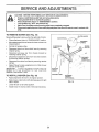
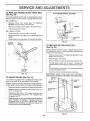
TO REMOVE
......................
MOWER
=
...................
,,,
_ ,
,J,,
(See Fig. 18)
CLUTCH
J L_
,
LEVER
Mower will be easier to remove from the right side of tractor
°
°
Place attachment clutch in "DISENGAGED" position
Move attachment lift [eve r forward to lower mower to its
lowest position,
-
Roll belt off engine pulley.
°
Disconnect clutch rod from clutch lever by removing
retainer spring_
°
Disconnect anti-sway bar from chassis bracket by
removing retainer spring.
*
Disconnect suspension arms from rear deck brackets
by removing retainer springs
o
Disconnect front links from deck by removing retainer
springs.
.
Raise lift lever to raise suspension arms Slide mower
out from under tractor.
CLUTCH ROD \_
RETAINER
SUSPENSION
' _%"RETAINER
_:
SPRINGS
i
IMPORTANT:
IF AN ATTACHMENT OTHER THAN THE
MOWER IS TO BE MOUNTED TO THE TRACTOR,
REMOVE THE FRONT LINKS
RETAINER
SPRING
ANTI-SWAY
TO INSTALL
MOWER
(See Fig. 18)
o
Raise attachment lift lever to its highest position
=
Slide mower under tractor with discharge guard to right
side of tractor.
•
=
Lower lift lever to its lowest position
Install mower in reverse order of removal instructions
ENGINE
PULLEY
BAR
RETAINER
SPRINGS
(BOTH SIDES)
FIG. t 8
21
.(BOTH SIDES)
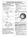
FRONT-TO-BACK ADJUSTMENT (See Figs. 21 and 22)
IMPORTANT; DECK MUST BE LEVEL SIDE-TO-SIDE. IF
THE FOLLOWING FRONT-TO-BACK ADJUSTMENT IS
NECESSARY, BE SURE TO ADJUST BOTH FRONT LINKS
EQUALLY SO MOWER WILL STAY LEVEL SIDE-TOSIDE,
Adjust the mower while tractor isparked on level ground or
driveway_ Make sure tires are properly inflated (See
"PROD UCT SPECIFICATIONS" on page 3 of this manual).
h tires are over or' underinfiated, you will not properly adjust
your mower=
SIDE-TO-SIDE
ADJUSTMENT
•
Raise mower' to its highest position.
=
Atthe midpoint of both sides of mower, measure height
from bottom edge of mower to ground Distance "A" on
both sides of mower should be the same or within 1/4"
of each other'.,
=
If adjustment is necessary, make adjustment on one
side of mower only
o
*
To obtain the best cutting results, the mower housing
should be adjusted so that the front is approximately 1/8" to
1/2" lower than the rear' when the mower is In its highest
position.
(See Figs. 19 and 20)
Check adjustment on right side of tractoL Measure distance "D" directly in front and behlnd the mandrel at bottom
edge of mower' housing as shown
o
To raise one side of mower, tighten lift link adju_;tment
nut on that side.
Before making any necessary adjustments, check that
both front links are equal in tength_ Both links should
be approximately 10-3/8".
=
To lower one side of mower', loosen lift link adjustment
nut on that side..
.
If links are not equal in length, adjust one link to same
length as other link.
To lower front of mower loosen nut "E" on both fronf
links an equal number of turns.
When distance "D" is 1/8" to 1/2" lower at front than
rear, tighten nuts "F" against trunnion on both front _
links.
NOTE: Each full turn of adjustment nut will change mower
height about 1/8".
o
Recheck measurements
-
after adjusting.
BOTTOM EDGE
OFMOWERTO
GROUND
I
BOTTOM EDGE
OF MOWERTO
GROUND
°
To raise front of mower, loosen nut"F" from trunnion on
both front links Tighten nut "E" on both front links an
equal number of turns.
When distance "D" is 1/8" to 1/2" lower at front than
rear', tighten nut "F" against trunnion on both front links,
Recheck side-to-side adjustment.
A
•
GROUNDLINE
,
MANDREL
FIG. 19
FIG. 21
BOTH FRONT LINKS MUST BE EQUAL IN LENGTH
LIFT LINK
ADJUSTMENT
NUT
FIG. 20
NUT
FRONT LINKS
22
TRUNNION
FIG= 22
"E"
•
, .........................
iir1,111
u .................... rrll ,,
I' ,,,r..............
,
m
•
SERVICE AND ADJUSTMENTS
i n u,,,i.....
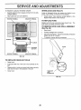
TO REPLACE
(See Fig. 23)
MOWER
BLADE
DRIVE
BELT
W|TH
lU, ,,,11,,,
PARKING
BRAKE
"ENGAGED"
The mower blade drive belt may be replaced without tool&
Park the tractor on level surface. Engage parking brake,
BELT REMOVAL o
Remove mower from tractor (See "TO REMOVE
MOWER" in this section of this manual),,
,,
Work belt off both mandrel pulleys and idler pulleys,
•
Pull belt away from mower
JAM NUT
/
/
-_
OPERATING
ARM
BELT INSTALLATION •
Install new belt in reverse order of removal,
.
°
Make sure belt is in aft pulley grooves and inside aII beit
guides
Install mower in reverse order of removal instructions
J
FIG. 24
MANDREL
PULLEY
IDLER
PULLEYS
TO REPLACE
(See Fig. 25)
MOTION
DRIVE
BELT
Park the tractor on [evet surface. Engage parking brake,
For assistance, there is a belt installation guide decal on
bottom side of left footresL
MANDREL
PULLEY
BRAKE
Remove mower (See "TO REMOVE MOWER" in this
section of this manual.,)
o
Remove upper belt keeper.
o
o
Remove belt from stationary idler and clutching idler
Pufl bert slack toward rear of tractor,, Remove belt
upwards from transaxle pulrey by deflecting belt keepers,
•
PulI belt toward front of tractor and remove downwards
from around engine pulley
o
Install new belt by reversing above procedure,
IMPORTANT:
MAKE SURE UPPER BELT KEEPER IS
POSITIONED PROPERLY BETWEEN LOCATOR TABS,
FIG. 23
TO ADJUST
o
(See Fig. 24)
ENGIt_
PUt .EY
Your tractor is equipped with an adjustable brake system
which is mounted on the right side of the transaxle,
TABS
IDLER
If tractor requires more than six (6) feet stopping distance
at high speed in highest gear, then brake must be adjusted,,
°
Depress clutch/brake pedal and engage parking brake.
.
Measure distance between brake operating arm and
nut "A" on brake rod
°
If distance is other than 1-1/2", loosen jam nut and turn
nut"A" until distance becomes !-1/2"
Retighten jam
nut against nut "A"
.
Road test tractor for proper stopping distance as stated
above° Readjust if necessary, if stopping distance is
still greater than six (6) feet in highest gear, further
maintenance is necessary, Contact your nearest authorized service center/departmento
KEEPER
IDLER
PULLEY
FIG. 25
23
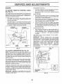
TRANSAXLE
SHIFTER
LINKAGE
JUSTMENT (See Figs. 26 and 27)
AND
AD-
TO REMOVE WHEEL
(See Fig. 28)
FOR REPAIRS
The transaxle should be in neutrat when the gear shift lever
i_ in the neutrat (N) (fock gate) position. The adjustment is
preset at the factory; however, if adjustment is needed,
proceed as follows:
•
Block up axle securety_
o
•
Make sure transaxle is in neutral (N).
Loosen two locknuts on tie rod.
=
Repair tire and reassemble,,
°
°
Turn center' rod until gearshift lever falls into neutral
lock gate on fender console.
On rear wheels only: align grooves in rear wheel hub
and axle Insert square key.,
°
Replace washers and snap retaining ring securely in
axle groove
o
Replace axle cover.
Remove axte cover, retaining dng and washerstoalloW
wheel removal (rear wheel contains a square key * Do
not lose).
Tighten Iocknuts securely,
._,-......<
_
NOTE: To seat life punctures and prevent fiat tires due to
slow leaks, tire sealant may be purchased from your local
parts dealer_ Tire sealant also prevents tire dry rot and
corrosion,
GEARSHIFTLEVER
WASHERS
RETAINING
RING
FIG. 26
LOCKNUTS
t
AXLECOVER
CENTER ROD
(REAR WHEEL ONLY)
FIG. 28
TO START ENGINE WITH A WEAK BA'I-I'ERY
(See Fig, 29)
TRANSAXLE
,_ _
_,
'
-......
STEERING
WHEEL
ALIGNMENT
IMPORTANT:
YOUR TRACTOR iS EQUIPPED WITH A 12
VOLT NEGATIVE
GROUNDED
SYSTEM.
THE OTHER
VEHICLE
MUST ALSO
BE A 12 VOLT
NEGATIVE
GROUNDED
SYSTEM.
DO NOT USE YOUR TRACTOR
BATTERY TO START OTHER VEHICLES°
if steering wheel c{ossbars are not horizontal (left to right)
when wheels are positioned straight forward, remove steering wheel and reassemble per' instructions in the Assembly
section of this manual
TO ATTACH JUMPER CABLES -
TOE-IN/CAMBER
o
The front wheel toe-in and camber are not adjustable on
your tractor_ tf damage has occurred to affect the front
wheel toe-in or' camber, contact your nearest authorized
service center/department_
°
FRONT
WHEEL
i1,,, , ,111111,
If your battery is too weak to start the engine, it should be
recharged.
If "jumper cables" are used for emergency
starting, follow this procedure:
FIG. 27
TO ADJUST
ateexplosivegases. Keepsparks,ftame
CAUTION:
and
smokingLead-acid
materials batteries
away from
generbatteries.
Always wear eye protection
when around batteries
.
24
Connect each end of the RED cable to the POSITIVE
(+) terminal of each battery, taking care notto short
against chassis.
Connect one end of the BLACK cable to the NEGATIVE (-) terminal of fully charged battery:
Connect the other end of the BLACK cable to good
CHASSIS GROUND, away from fuel tank and battery.
=,
=
.........................
=,.,.,,
$ERVUCE AN
n= =
,
ADJUSTMENTS
.......................
i ,,,,..
. n
TO REMOVE CABLES, REVERSE ORDER -
INTERLOCKS
o
Loose or damaged wiring may cause your tractor to run
poorly, stop running, or prevent it from starting.
•
BLACK cable first from chassis and then from the fully
charged battery..
RED cable last from both batteries,
POSITIVE TERMINAL
NEGATIVE
•
AND RELAYS
Check wiring° See electrical wiring diagram in the
Repair Parts section of this manual,
TERMINAL
TO REPLACE
FUSE
Replace with 30 amp automotive-type phJg-in fuse.
fuse holder is located behind the dash.
TO REMOVE HOOD
(See Fig. 30)
AND GRILL
Raise hood°
=
Unsnap headlight wire connector°
-
Stand in front of tractor G rasp hood at sides, tilt toward
engine and lift off of tractor.
-
To replace, reverse above procedures.
HOOD
NEGATIVE
TERMINAL
FIG, 29
TO REPLACE
HEADLIGHT
BULB
°
Raise hood,
=
Pull bulb holder out of the hole in the backside of the
grill.
•
Replace bulb in holder and push bulb holder securely
back into the hole in the backside of the grill.
Close hood
•
I-]EADLIGHT
'WIRE
CONNECTOR
FIG. 30
25
ASSEMBLY
,
CHARGED
BATTERY
POSITIVE TERMINAL
The
-
iii ....
,111
.....iiiii
iiii
SERVSCE AND ADJUSTMENTS
'II'IMI I"
'11'1 '
ENGINE
I
'11
PRELIMINARY SETTING -
TO ADJUST
THROTTLE
(See Fig. 31)
CONTROL
o
Air cleaner assembly must be assembled to the carburetor when making carbu[etor adjustments_
o
Be sure the throttle control cable is adjusted properly
(see above)_
FINAL SETTING -
CABLE
The throttle control has been preset at the factory and
adjustment should not be necessary.. Check adjustment as
described below before loosening cable., tf adjustment is
necessary, proceed as follows:
=
With engine not running, move throttle control lever
from slow to choke position Slowly move lever from
choke to fast position.
o
Check that holes "A" in governor control lever and hole
in governor plate line-up. If holes "A" are not aligned,
loosen clamp screw and move throttle cable untif holes
are aligned° Tighten clamp screw securely°
GOVERNOR
CONTROL LEVER
o
=
o
GOVERNOR
CONTROLPLATE
ACCELERATION
"
HOLES"A"
CLAMP
SCREW
CARBURETOR
TEST -
Move throttle control lever from slow to fast position., If
engine hesitates or dies, turn idle mixture valve out
(counterclockwise)
1/8 turn. Repeat test and continue
to adjust,
if necessary,
until engine
accelerates
smoothly
High speed stop is factory adjusted.
Do not adjust damage may result
IMPORTANT:
NEVER TAMPER
W1TH THE ENGINE
GOVERNOR,
WHICH IS FACTORY SET FOR PROPER
ENGINE SPEED OVERSPEEDINGTHEENGtNEABOVE
THE
FACTORY
HiGH
SPEED
SETTING
CAN
BE
DANGEROUS
IFYOUTHINKTHEENGINE-GOVERNED
HIGH SPEED NEEDS ADJUSTING,
CON I'CT
YOUR
NEAREST
AUTHORIZED
SERVICE
CENTER/
DEPARTMENT,
WHICH HAS PROPEREQb
_MENTAND
EXPERIENCE
TO
MAKE
ANY
NECESSARY
ADJUSTMENTS
THROTTLE
CABLE
IDLE SPEED
FIG. 31
TO ADJUST
Start engine and allow to warm for five minutes. Make
final adjustments with engine running and shift/motion
control lever in neutral (N) position.
Move throttle control lever to slow position, With finger,
rotate and hold throttfe lever against idle speed screw.
Turn idle speed screw to attain 1750 RPM.
While stiif holding throttle {ever against idle speed
screw, turn idle mixture valve fu{l travel clockwise then
counterclockwise until engine runs rough. Turn valve
to a point midway between those two positions. Release throttle lever..
THRL, ;'TLE
(See Fig. 32)
NOTE: The carburetor on this engine is low emission it is
equipped with an idle fuel adjusting needle with a limiter
cap, which allows some adjustment within the limits allowed bythecap_ Donot attempt to remove thelimiter cap
The limiter cap cannot be removed without breaking the
adjusting needle.
The carburetor has been preset at the factory and adjustmerit should not be necessary.. However', minor adjustment may be required to compensate for differences in fuel,
temperature, altitude or load. If the carburetor does need
adjustment, proceed as follows:
in general, turning idle mixture valve in (clockwise) decreases the supply of fuel to the engine giving a leaner fuel/
air mixture. Turning the idle mixture valve out (counterclockwise) increases the supply of fuei to the engine giving
a richer fuel/air mixture.
IMPORTANT:
DAMAGE TO THE NEEDLE
THE SEAT IN CARBURETOR
MAY RESULT
TURNED IN TOO TIGHT,_
VALVE
AND
iF SCREW IS
LIMITER
FIG. 32
26
i
. ...ll.l.l-..U,Ul
....n...i.r.
. u...........
i..
STORAGE
...
i.i..i
....... ir.llll
.....
..i
. i...Ul..U.
.i...
before storing in a.ny,enclos,ure. ,,
r.....
...............
_..._
FUEL SYSTEM
m
IMPORTANT:
IT IS IMPORTANT TO PREVENT GUM
DEPOSITS FROM FORMING IN ESSENTIAL
FUEL
SYSTEM PARTS SUCH AS CARBURETOR, FUEL FILTER,
FUEL HOSE, OR TANK DURING STORAGE.
ALSO,
EXPERIENCE INDICATES THAT ALCOHOL BLENDED
FUELS (CALLED GASOHOL OR USING ETHANOL OR
METHANOL) CAN ATTRACT MOISTURE WHICH LEADS
TO SEPARATION AND FORMATION OF ACIDS DURING
STORAGE,
ACIDIC GAS CAN DAMAGE THE FUEL
SYSTEM OF AN ENGINE WHILE IN STORAGE
where
fumes
may
reach
an open
flame
gasoline
in the
tank
inside
a building
or
spark. Never
Allow store
the engine
to cool
CAUTION:
the tractor
with
I
. .i.u.i
ENGINE
immediately prepare your tractor for storage at the end of
the season or if the tractor will not be used for 30 days or
mo re.
.....
i..i....., i
B
TRACTOR
Remove mower from tractor for winter storage, When
mower is to be stored for a period of time, clean it thoroughly, remove all dirt, grease, feaves, etc, Store in a
clean, dry area.
o
Clean entire tractor (Sea"CLEANING*' in the Customer
Responsibilities section of this manual),
.
Inspect and replace belts, if necessary (See belt replacement instructions in the Service and Adjustments
section of this manual)
°
Lubricate as shown in the Customer Responsibilities
section of this manual.
*
Be sure that all nuts, bolts and screws are securely
fastened. Inspect moving parts for damage, breakage
and wear, Replace if necessary.
o
Touch up all rusted or chipped paint surfaces; sand
iightly before painting
Fully charge the battery for storage,
o
After a period of time in storage, battery may require
recharging.
Drain the fuel tank.
o
Start the engine and let it run until the fuel Iines and
carburetor are empty_
a
Never use engine or carburetor cleaner products in the
fuel tank or permanent damage may occur.
Use fresh fuel next season.
o
NOTE:
Fuel stabilizer is an acceptable alternative in
minimizing the formation of fuel gum deposits during storage Add stabilizer to gasoline in fuet tank or storage
container Always fotlow the mix ratio found on stabilizer
container. Run engine at least 10 minutes after adding
stabilizer to allow the stabilizer to reach the carburetor. Do
not drain the gas tank and carburetor if using fuel stabilizer.
ENGINE
OIL
Drain oil (with engine warm) and replace with clean engine
oil. (See "ENGINE" in the Customer Responsibilities
section of this manual).
BATTERY
=
°
CYLINDERS
•
Remove spark plug(s)
To help prevent corrosion and power leakage during
long periods of storage, battery cables should be
disconnected and battery cleaned thoroughly (see "TO
CLEAN BATTERY AND TERMINALS" in the Customer Responsibilities section of this manual),
o
Pour one ounce of oil through spark plug hole(s) into
cylinder(s),
=
Turn ignition keyto"START"position
to distribute oil
After cleaning, leave cables disconnected and place
cables where they cannot come in contact with battery
terminals,
o
Reptac _ with new spark plug(s).
o
Be sure battery drain tube is securely attached.
o
Do not store gasoline from one season to another.
o
If battery is removed from tractor for storage, do not
store battery directly on concrete or damp surfaces,
.
Replace your gasoline can if your can starts to rust
Rust andfor dirt in your gasoline will cause problems
If possible, store your tractor indoors and cover it to
give protection from dust and dirt
•
•
for a few seconds
OTHER
.
=
Cover your tractor with a suitable protective cover that
does not retain moisture Do not use plastic. Plastic
cannot breathe which allows condensation to form and
will cause your tractor to rust
IMPORTANT: NEVER COVER TRACTOR WHILE ENGINE
AND EXHAUST AREAS ARE STILL WARM
27
i
ii
un
i
, ii
=FRO
U l ......
i
LESHOOTING
PROBLEM
CAUSE
Will not start
1
Out of fuel
2
3
4
5
6
7
Engine not "CHOKED"
Engine flooded
Bad spark plug
Dirty air filter
Dirty fuel filter
Water in fuel
8
9
Loose or damaged wiring
Carburetor outof adjustment
10
Hard to start
JJiuJuJ
illUU_ ....
CORRECTION
properly
Engine vaJves out of adjustment
1
Fill fuel lank
2
3
4
5
6
7
Sea"TO START ENGINE' in Operation section
Wait severaI minutes before attemptir_g to start
Replace sped< plug
Clean/replace air filter
Replace fuel fiiter
Drain fuel tank and carb,_retr)r refill tahk with fresh
8
9
gasoline and replace ;_el filter
Check nil wiring.
See 'To Adjust Carbu_eb:," It, Survice Adjustments
sectior'
10.
Confucian
autho_iz_.d serv!ce center/department.
1
2
3
4
5
6
7
Dirty air filter
Bad £parl_'plug
Weak or dead battery.
Dirty fuel filter
Stale or dirty fuel
Loose or damaged wiring
Carburetor out of adjustment
1
2
3
4
5
6
7
Clean#apiece air filter
Replace spark plug
Recharge or replace battery
Replace fuel filter
Dram fuel tank end refill with fresh gasoline
Check a!l wiring
See "To Adjusl Carburetor" in Service Adjustments
section
8
Engine valves out of adjustment
8
Contact an authorized
t
2
3
4
Clutch/brake pedal not depressed
Attachment dutchts engaged
Weak or dead battery
Blown fuse
5
6
7
8
9.
Corroded battery terminals
Loose or damaged wtdng
Faulty ignilion switch
Faulty solenoid or stealer
Faulty operator presenceswitch(es).
,i, i, i
1
2
3
4
5
6
7
8
9
r
i,,i,1,1
ii1,,11,11111,
i .....
iiii
1
2
3
4.
Weak or dead battery
Corroded battery terminals
Loose or damaged wiring
Faulty solenoid or starter:
2
3
4;
Loss of power
1
2
3
4
5
6
7
8
9
Cutting too much grass/too fast
Throttle in "CHOKE" position.
Build-up of grass, leaves and trash under mower,
Dirty air filler
Low oil level/dirty oil
Faulty spark plug
Dirty fuet f{Iter
Stale or dirty fuel
Water in fuel
1
2
3
4
5
6
7
8
9
lU
Excessive
service centeddepartment
•
.
10
1t
12
13
14
Spark plug wire loose
Dirty engine air screen/fins
Dirty/clogged muffler
Loose or damaged wiring
Carburetor out of adjustment
10
1t
12
13
14
l&
Engine valves out of adjustment
15
:
Depress clutch/brake pedal
Disengage attachment clutch
Recharge or reptace battery
Replace fuse
Clean battery _erminats
Check all wiring
Check/replace ignition swifch
Chectdreplace solenoid or stealer
Contact an authorized service centeddepartment.
i
Engine clicks but will not
start
i , n nn ii
:
POINTS
H.................... n
Engine will not turn over
,,
i
Recharge or replace battery
Clean battery fermina_s
Check eli wiring
Checldrep_ace solenoid or starter.
Set in "Higher Cut" position/reduce speed
Adjust throttle control
Clean underside of mower housing
Clean/replace air Iilfer
Check oi! leveVchange oil
Clean and regap or change spad_ plug
Replace fue_ filter
Drain fuel tank and refitl with fresh gasoline
Drain fuel tank and carburetor, refill tank with fresh
gasoline and replace fuel filter
Connect and tighten spark plug wire
Clean engine air screen/lies
Clean/replace muftler
Check all wiring.
See "To Adjust Carburetor" in Service Adjustments
section
Contact an authorized
service center/department
,n,,n
vibration
1
2
Worn, bent or loose blade
Bent blade mandrel
3
Loose/damaged
1
2
3
part(s)
28
Replace blade Tighten blade bolt
Replace blade mandrel.
Tighten loose part(s) Replace damaged parts
, u ,,
L
i
, i i,,,u,l,u¸
,
TROUBLESHOOTmNG
, iii
.....
POmNTS
n,l,,
PROBLEM
CAUSE
CORRECTION
u,u ....
I
Engine continues to run
when operator leaves seat
with attachment clutch
,
, ,,, Ul,,,i
u,
Check wiring, switches and connections
tf not
corrected, contact an authorized service center/
Faulty operator-safety presence control system
department
engaged
, i, nl,
,i
Poor cut - uneven
1
2
3
4
5
Worn, bent or loose blade
Mower deck not level.
Buildup of grass, leaves, and trash under mower
Bent blade mandrel
Clogged mower deck vent holes from buildup of
grass, ieaves, and trash around mandrels
1
2
3
4
5
Replace bfade Tighten blade bolt
Level mower deck
Clean underside of mower housing
Replace blade mandrel
Clean around mandrels to open vent holes
I
2
3
4
Obstruction in clutch mechanism
Worn!damaged mower drive belt
Frozen idler pulley
Frozen blade mandrel
t
2
3
4
Remove
Replace
Replace
Replace
Engine speed too slow
Travel speed too fast
Wet grass
Mower deck not ievel
Low/uneven tire air pressure
Worn, bent or loose blade
Buildup of grass, leaves and trash under mower
Mower drive beIt worn
Blades improperly installed
improper blades used
Clogged mower deck vent hoies from buildup of
grass, leaves, and trash around mandrels
1
2
3
4
Place throttle control in "FAST" position
Shift to slower speed
Allow grass to dry before mowing
Level mower deck
m
Mower blades will not
rotate
obstruction
mower drive belt
idler putley
blade mandrel
, lun, n,
Poor grass discharge
1
2
3
4
5
6
7
8
9
tO
11
5
6
7
8
9
10
11
Checktires for proper air pressure
Replace/sharpen blade Tighten blade bolt
Clean underside of mower housing
Replace mower drive belt
Reinstall biades sharp edge down
Repiace with blades listed in this manual
Clean around mandrels to open vent holes
,,n,i
Headlight(s)
not working
(if so equipped)
Battery will not charge
Engine "backfires"
when turning engine
"OFF"
1
Switch is "OFF"
1
Turn switch 'ON"
2
3
4
5
Bulb(s) burned out
Faulty light switch
Loose or damaged wiring
Blown fuse
2
3
4
5
Replace bulb(s)
Checldreplace ligl;t switch
Check wiring and connections
Replace tuse
1
2
Bad battery ceif(s)
Poor cable connections
1
2
Reptace battery
Check/clean atl connections
3
4
Faulty regulator (if so equipped)
Faufty alternator
3
4
Replace regulator
Replace alternator
1
Engine throttle control no1 set at 'SLOW"
position for 30 seconds before stopping engine
29
Move throttle control to "SLOW" position and atlow
to idle for 30 seconds before stopping engine
30
TRACTOR
- - MODEL NUMBER
917.270610
SCHEMATIC
+111o
BATTERY
oqr+i .ED
I ......
__
RED
FUSE
30 AMP.
STARTER
[---_---++
)
WHITE
;O
BLACK
', O+_
SOLENOID
L .......
J
CLUTCH / BRAKE
(PEDAL UP)
WHITE
IGNITION
SWITCH
/__)G
(NOT OCCUPIED)
........
SEAT SWITCH t
L+
wE
(
BLACK
I
I
I
I
f
o
I
"3
i
I
_o:i.'
t
!-,,
"_l'
Cj-.._A H---.... ,,
_l
GROUNDING
(CLUTCH OFF)
J
CONNECTOR
0LAoK
METER
HOUR
(OPTIONAL)
h____J_
BLACK
IGNITION
UNIT
FUEL1
I
SPARK
PLUG
_2
GAP ON_
(2 PLUGS
m
TWIN CYL ENGINES)
CHARGING SYSTEM OUTPUT
3 AMP DC @ 3800 RPM
FUEL SHUT-OFF
SOLENOID
LIGHTING
5AMPAC
ORANGE
28 VOLTS AC MIN. @ 3600 RPM
(CHARGING SYSTEM DISCONNECTED}
BLUE
I
SYSTEM OUTPUT
@ 3G00 RPM _
__
j_p_
r'_Et'_,m _
u_,_
, ,&/TI_I::IM_,Tt"31_
................
I I
{ I
NOTE
IGNITION SWITCH
POSITION
OFF
RUN/LIGHT
OlROU|T
G+ M + L
"MAKE*"
NONE
B+L
A+Y
RUN
B + L
NONE
START
B+ L+ S
NONE
YOUR TRACTOR IS
EQUIPPED WITH A SPECIAL
BROWN
ALTERNATOR SYSTEM+
THE LIGHTS ARE NOT
CONNECTED TO THE
BATTERY, BUT HAVE THEIR
OWN ELECTRICAL SOURCE.
BECAUSE OF THIS, THE
BRIGHTNESS OF THE LIGHTS
WILL CHANGE WITH ENGINE
SPEED. AT IDLE THE LIGHTS
WILL DIM. AS THE ENGINE IS
NON-REMOVABLE
SPEEDED UP, THE LIGHTS
CONNECTIONS
WILL BECOME THEIR BRIGHTEST.
HEADLIGHTS
®
O
REMOVABLE
CONNECTIONS
WIRING INSULATED CLIPS
NOTE: IF WIRING INSULATED CLIPS WERE REMOVED FOR
SERVICING OF UNIT, THEY SHOULD BE REPLACED TO
PROPERLY SECURE YOUR WIRING,
31
/-2-7
REPAIR PARTS
TRACTOR
- - MODEL NUMBER
917.270610
ELECTRICAL
\
21
41
7O
26
20
t
,
25
6
•
16
/
/
/
33
\
\
\
32
REPAmR PARTS
TRACTOR
- - MODEL NUMBER
917.270610
ELECTRICAL
KEY
NO.
PART
NO,
1
2
3
4
6
8
16
19
20
2t
22
24
25
26
28
29
3O
31
32
33
40
41
42
43
44
45
52
70
144925
747604'12
S_D551025
STD551125
STD541025
156417
153664
STD551t25
73350400
147430
4152J
4799J
146147
108824X
4207J
121305X
14O3O1
124211X
141226
1093t0X
156442
71110408
131563
145673
73640400
121433X
141940
14.0422
DESCRIPTION
Battery 12 VOLT 25 AMP
Bolt Hex Hd I/4-20unc x 3/4
Washer 9/32 x 5/8 x t6 Ga
Washer Lock Hvy Hetical 1/4
Nut Fin Hex 1/4-20 Unc
Case Battery
Switch, Interlock Push-in
Washer Loci{ 1/4
Nu[ Jam Hex 1/4-20 Unc
Harness Asm Light W/4152j
Bulb Light #1 t56
Cable Battery 6 Ga 11" red
Cable Battery 6 Ga w/16 wire red
Fuse 30 AMP Auto Green
Cable Ground 6 Ga 12" black
Switch Plunger Nc Gray
Switch Ign 4 Pos
Nut Ignition
Cover Sw Key BIk 1 25 Text SLT
Key lgn Molded Craftsman
Harness Ign Man Cl Am Hm 97
Bolt Blk. Fin Hex 1/4_20 Unc x 1/2
Cover Terminal Red
Solenoid
Nut Keps BIk Hex 1/4-20 Unc
Ammeter Rectangular 6 Amp
Protection Wire Loop
Harness Engine B&S 14 OHV
NOTE: All component dimensions give in US, inches
1 inch = 25,4 mm
33
REPAHRPARTS
TRACTOR
CHASSIS
- - MODEL NUMBER
917.270610
AND ENCLOSURES
28
25
5
53
26
51
5
55
57
15
14
L
54
..,j
140
26
33
10
35
14
26
34
REPAUR PARTS
TRACTOR
CHASSIS
- - MODEL NUMBER
917.270610
AND ENCLOSURES
KEY
NO.
PART
NO.
1
2
3
4
5
6
6
9
10
11
12
13
14
15
159530
140356
17490612
STD551025
155272
155924X015
155138
147633X010
STD533710
155927
145660
155934X010
1749O608
74180512
16
17
!8
24
25
26
28
29
30
3t
33
34
35
37
38
39
51
52
53
54
55
57
140
t45
--
STD541431
144983X558
126936X
STD523710
19131312
STD541437
145198X558
155127
157584X558
136619
145244X558
145243X558
STD533707
17490508
'139886
139887
73800400
19091416
145201
161464
145202
STD522507
158418
156524
5479J
NOTE:
DESCRIPTION
Chassis Assembly
Drawbar
Screw, Thd Roll. 3/8-16 x 3/4
Washer 13/32 x 3/4 x 16 Gauge
Bumper Hood/Dash
Saddle
Clip Retainer Slide-On
Dash
Bolt, Carriage 3/8-16 x 3/4
Panel, Dash, LH.
Clip Tinnerman Grille P/L
Panel, Asm. SLKSCR Dash R.H
Screw Thdrol 3/8-16 x 1/2
Screw, Machine, Truss Head
5/16-18 UNC x 3/4
Nut
Hood Assembly
Bumper Hood
Bolt
Washer 13/32 x 13/16 x 12 Gauge
Nut
Grille w/Clips MS-558
Lens, Grille
Fender
Bracket, Fender Support
Footrest, LH,
Footrest, R.H
Bolt
Screw Thdrol 5/16-18 x 1/2 TYT
Pivot Bracket Assembly, L.H.
Pivot Bracket Assembiy, R.rH.
Nut Lock w/Insert 1/4-20 UNC
Washer 9/32 x 7/8 x !6 Ga,
Bracket Grille Pickoff LH
Screw Hex WSHD 8-18 x 7/8
Bracket Grille Pickoff RH
Bolt, Fin Hex 1/4-20 UNC x .75
Bracket Front Suspension
Rod Pivot Chassis/Hood
Plug, Button
AII component dimensions given in U S inches
1 inch = 254 mm
35
REPAnR PARTS
TRACTOR
- - MODEL NUMBER
917.270610
DRIVE
32
3O
52
62
35
77
37
34
19
i
26
27
36
RE!PAreR
PARTS
TRACTOR
- - MODEL NUMBER
917.270610
DRIVE
KEY
NO.
2
3
4
5
6
7
8
10
11
12
13
14
15
18
19
2I
22
24
25
26
27
28
29
3O
31
32
34
35
36
37
38
39
PART
NO.
146682
123666X
12000028
121520X
17490512
130802
131679
STD561210
105701X
t9!51216
74550412
STD551125
74490544
STD5237t0
STD541437
108933X
130804
STD541237
106888X
STD551037
STD561210
145204
124236X
130807
127275X
STD523107
155071
120183X
STD551062
STD571810
123674X
STD523727
DESCRIPTION
Transaxle (See Breakdown)
Dana Model 4360-113
Spring Return Brake T/a Zinc
Pulley Transaxie !8/20" tires
Ring Retainer # 5100-62
Strap Torque 30 Degrees
Screw Thdrol 5/16-18 x 3/4 TYT
Bracket Saddle Shift "i"ia
Rod Shf Sdl LY/YT Str BIk Zinc
Pin Cotter 1/8 x I Cad
Washer Plate Shf 388 Sq Hole
Washer 15/32 x 3/4 x 16ga
Bolt 1!4-28unf Gr8 W/Patbh
Washer Lock Hvy Helical 1/4
Bolt Hex FLGHD 5/16-18Gr.5
Bolt Fin Hex
Nut Lock Hex W/Ins., 3/8-16 Uric
Knob Rd 1/2413 Plstc Thds BIk
Rod Brake Blk Zinc 26 840
Nut Hex Jam 3/8-16 Uric
Spring Rod Brake 2 00 Zinc
Washer 13/32 x 13/16 x 16 Ga
Pin Cotter 1/8 x 3/4 Cad
Rod Brake Parking Lt/Yt
Cap Brake Parking Red
Bracket Mtg Transaxte
Keeper Belt LH LT 14 Ga
Bolt Hex Hd 5/16-18unc x 3/4
Shaft Asm Pedal Foot
Bearing Nylon Btk 629 Id
Washer 21/32 x I x 16 Ga
Pin Roll 3/16 x 1"
Pulley Idler Fiat
Boil Fin Hex 3/8-16unc x 2-3/4
KEY
NO.
PART
NO.
4O
41
42
47
48
49
50
51
52
53
55
56
57
58
59
61
62
63
64
65
66
70
72
74
75
76
77
78
112
116
1!8
121
4470J
154777
19131312
127783
154604
123205X
STD523715
STD541437
STD541431
105710X
105709X
STD523712
130801
127274X
140312
17490612
8883R
140186
71170764
STD551143
154778
134683
19132012
109502X
121749X
STD581075
123583X
121748X
19091210
72110610
154774
154419
NOTE:
37
DESCRIPTION
Spacer Split 395 x 59 Bzp
Keeper Belt Idler
Washer 13/32 x 13/16 x !2 Ga
Pulley Idler V Groove Plastic
Beltcrank Asm Clutch
Retainer Belt Style Spring
Bolt Hex Hd 3/8-16unc x 1-1/2
Nut Crowntock 3/8-16 UNC
Nut Crown Lock 5/t6-18
Link Clutch 7 66
Spring Return Clutch 6 75
Bolt Fin Hex 3/8-16 unc x 1-1/4
V-Belt Gd Drive 95 25
Keeper Belt RH LT Pnt/zinc 16g
Keeper Belt Centerspan
Screw Thdrol 3/8-16 x 3/4 Ty-tt
Cover Pedal BIk Round
Pulley Eng CI Mech 38deg LT/YT
Bolt Hex 7/16-20 x 4 Gr 5
Washer Lock Hvy Hlct Spr 7/16
Keeper Belt Engine
Guide Belt Mower Drive RH
Washer 13/32 x 1-1/4 x 12 Ga
Spacer Axle
Washer 25/32 x 1 1/4 x 16 Ga
E-ring #5133-75
Key Square 2 0 x 1845/1865
Washer 25/32 x 1-5/8 x 16ga
Washer 9/32 x 3/4 x 10 Ga
Bolt Rdhd Sq Neck 3/8-16 x 125
Spacer Bellcrank
Nyliner Clutching Stl
All component dimensions
1 inch = 25°4 mm
given in USo inches
"MODEL NUIIi181_R917"270610
\
\
\
\
REPAIR PARTS
TRACTOR
STEERING
- - MODEL NUMBER
917.270610
ASSEMBLY
KEY
NO.
PART
NO.
1
2
3
4
5
6
7
8
9
10
11
13
15
17
18
19
20
22
23
25
26
27
28
29
30
32
36
37
38
39
40
41
42
43
44
46
47
51
54
62
63
65
66
67
68
139768
154427
156483
t57473
6266H
121748X
19272016
12000029
3366R
156438_
STD551137
154779
73901000
156546,
57079
124035X
126684X
71200410
127501
154406
126847X
136874
19131416
17490612
STD561210
130465
155099
152927
139769
19133808
STD541537
1007!1L
145054
121749X
153720
121232X
6855M
STD541431
STD523112
156594
74780616
154780
154404
74781044
154429
NOTE:
DESCRIPTION
Steering Wheel
Front Axle Assembly
Spindle Assembly, LH.
Spindle Assembly, RH.
Bearing, Race, Thrust, Hardened
Washer 25/32 x 1-5/8 x 16 Gauge
Washer 27/32 x 1-t/4 x 16 Gauge
Ring, Klip
Bearing, Steering Column
Link, Drag
Washer, Lock
Spacer, Bearing, Front Axle
Nut, Lock, Flange 5/8-11 UNC
Shaft Assembly, Steering
Washer, Thrust .515 x .750 x .033
Support, Shaft
Washer, Shim 1/4 x 5/8 x .062
Screw Hex Socket 1/4-20 x 5/8
Pittman Shaft Assembly
Bracket, Steering
Bushing, Link, Drag
Gear, Sector
Washer !3/32 x 7/8 x 16 Gauge
Screw, Thd., Roll 3/8-16 x 3/4
Pin
Rod, Tie
Bushing, Steering
Screw TT #10-32 x 5 x 3/8 Flange
Cap Wheel Steer OPP BIk
Washer 13/32 x 2-3/8 x 8 Gauge
G ripco Nut
Adaptor, Steering Wheel
Boot, Steering Dash P/L Mtl BIk
Washer 25/32 x 1-1/4 x 16 Gauge
Extension Steering Non-Adjust
Cap, Spindle
Fitting, Grease
Nut Lock Hx W/Ins 5/16-18 UNC
Bolt Fin Hex 5/16-18 UNC x 1-1/4
Kit, Steering Assembly, Service
Bolt Fin Hex 3/8_16 unc. x I Gr. 5
Spacer Axle
Bearing Arm Pittman
Bolt Fin Hex 5/8-1 lunc x 2-3/4
Brace Axle
All component dimensions
1 inch = 25,4 mm
39
given in U.S, inches
REPAIR PARTS
TRACTOR
- - MODEL NUMBER
917.270610
SEAT ASSEMBLY
5
KEY
NO.
PART
NO.
1
2
3
4
5
6
7
8
9
10
11
14O122
140551
STD523710
19131610
145006
STD541437
124181X
17490616
19131614
155925
120068X
DESCRIPTION
Seat 3350 BIk/blk Craftsman
Bracket Pnt Pivot Seat (blk)
Bolt Fin Hex 3/8-16unc X 1
Washer 13/32 X 3/4 X 10 Ga
Clip Push In Hinged
Nut Hex Lock w/Ins 3/8-t6 Unc
Spring Seat Cprsn 2 250 BIk Zi
Screw Thdrot 3/8-16 X 1 Ty-tt
Washer t3/32 X 1 X 14 Ga
Pan Pflt Seat (blk)
Knob Seat
KEY
NO.
PART
NO,
12
13
14
15
16
17
21
22
24
25
121246X
121248X
72050412
134300
121250X
t23976X
153236
STD541431
19171912
127018X
NOTE:
4O
DESCRIPTION
Bracket Pnt Mounting Switch
Bushing Snap BIk Nyl 50 Id
Boft Rdhd Sht Nk 1/4-20x1-1/2
Spacer Split 28 X 96 Zinc
Spring Cprsn ! 27 BIk Pnt
Nut Lock 1/4 Lge Flg Gr 5 Zinc
Bolt Shoulder 5/16-18 Unc-2A
Nut Hex Lock w/Ins 5/16-18
Washer' 17/32 X 1-3/16 X 12 Ga
Bolt Shoulder 5/16-18 X 62
All component dimensions given in U.So inches.
! inch = 25_4 mm
REPAnR PARTS
TRACTOR
- - MODEL NUMBER
917.270610
DECALS
!4
9
17
6
3
7
7
4
14
16
1't
1
12
13
10
18
15
KEY
NO.
1
2
3
4
6
7
9
10
11
12
13
PART
NO,
156834
273303
160280
160281
133644
150297
146709
149516
156439
4900J
146046
KEY
NO.
DESCRIPTION
Decal,
Decal,
Decal,
Decal,
Decal,
Decal,
Decal,
Decal,
Decal,
Decal,
Decal,
14
15
16
I7
18
---+--
Instruction Operat Eng
Engine
Hood Rh
Hood Lh
Maint Customer Sears Dom
Panel Side
Fender Craftsman Gold
Btry Dngr/Psn Eng
Fender Danger Sears E/S
Clutch/brake Eng
V-belt Dr Sch Tractor
4,10
7
11
PART
NO.
147139
160396
140837
150333
156787
138311
145246
145247
162029
162030
KEY
NO.
PART
NO.
I
2
3
4
5
6
7
8
9
t0
11
--
59192
65139
106222X
59904
106732X427
278H
9040H
106108X427
106268X
7152J
104757X
'144334
NOTE:
41
DESCRIPTION
Decal, Chassis 42" 6sp
Decal, Mower Drive Schematic
Decal, Saddle Brake Parking
Decal, Cap Cnsmr Help Line Srs.
Decal, Mower EZ3 Mulching Sears
Decal, Lift Handle
Pad, Footrest Rbr Sq Generic 95
Fastner Pop In Footrest
Manual, Owner's (English)
Manual, Owner's (Spanish)
DESCRIPTION
Cap Value Tire
Stem Value
Tire F Ts 15 X 6 0 - 6 Service
Tube Inner Front #35060
Rim Asm 6"front White Service
Fitting Grease
Bearing Flange
Rim Asm 8"rear White Service
Tire R Ts 18x9 5-8 Service
Tube Rear 9 5 X 8 Service
Cap Axle Blk 1 50 X 1 00
Sealant, Tire (10 oz. tube)
All component dimensions
1 inch = 254 mm
given in U, So inches+
REPAaR PARTS
TRACTOR
-- MODEL tXILIMBER 917.270610
ENGINE
72
62
81
13
14
23
29
/
\
OPTIONAL
F_QUIPMENT
Spark Arrester
42
4
REPAIR PARTS
TRACTOR
- - MODEL NUMBER
917.2706'I 0
ENGINE
KEY
NO.
1
2
3
PART
NO.
150600
t7720410
4
13
14
15
t6
23
29
31
32
33
35
37
38
137352
272293
13280324
13200300
STD551237
15988O
137180
109202X
158990
123487X
'17490512
137O4O
......
40
44
46
62
72
78
81
124028X
17490412
19091416
STD551131
71070512
17490620
128861
NOTE:
DESCRIPTION
Control TH/Ch LH IV 180.20.22"
Screw Hex Thd Cut 1/4-20x5/8 T
Engine (See Breakdown) B&S Model
28 U707-1174-E1
Muffler Exhaust B&S Lt
Gasket ! 3!3 Id Tin Plated
Nipple Pipe 3/8 Npt X 3"
Elbow Std 90 Degree 3/8-18 Npt
Washer Lock Ext Tooth 3/8
Shield BRN/DBR Guard
Arrestor Spark
Tank Fuel 1 25 Fr
Cap Asm Fuel W/sym Vented
Clamp Hose Btk
Screw, Thdrol 5/16_18 x 3/4 Tyt
Line Fuel 20"
Plug Oil Drain (Order From Engine
Manufacturer)
Bushing Snap Nyl BIk Fuel Line
Screw Hexwsh Thdrol 1/4-20x3/4
Washer 9/32 X 7/8 X 16ga
Washer Lock Hvy Hlcl Spr 5/16
Screw Hexhd Cap 5/t6-18x3/4
Screw Thd rol 3/8-16x 1- 1/4 Tytt
Nut Flange !/4-20 Starter Nut
All component dimensions given in U.S° inches
1 inch = 25.4 mm
43
REPAHRPARTS
TRACTOR
- - MODEL NUMBER
917.270610
LIFT
7
8
I
I
I
l
I
5
I
l
I
!'i
3
13
4
6
6
5
13
161718
19
15
32
44
20
REPAIR PARTS
TRACTOR
- - MODEL NUMBER
917.270610
LIFT
KEY
NO.
PART
NO.
159460
2
3
4
5
6
7
8
1I
12
13
15
16
17
18
t9
20
31
32
159471
t05767X
12000002
19211621
1201_3X
125631X
122365X
139865
139866
STD624008
127218
73350800
130171
73800800
139868
STD624008
140302
7354O600
NOTE:
DESCRIPTION
Washer Asm Inner Spring W/
Plunger
Shaft Asmo Lift RH
Pin Groove
E Ring #5133-62
Washer 21/32 x I x 21 Ga.
Bearing Nylong
Grip Handle Fluted
Button Plunger Read
Link Asm Lift LH.
Link Asm Lift R,H
Retainer Spring
Link Front
Nut,Jam Hex 1/2_13 Unc
Trunnion BIk Zinc
Nut Lock W/Wsh 1/2-13 Unc
Arm Suspension Mower
Retainer Spring
Bearing, Pvt. Lift. Spherical
Nut Crownlock 3/8_24
All component dimensions given in U,S, inches
1 inch = 25,4 mm
45
REPAIR PARTS
TRACTOR
- - MODEL NUMBER
917.270610
MOWER
76
68
34
,33
32
105
102
106
17
""_
105 _,_
106_
104
21 22
\
2
t6
28
29
18
21
13_
46
27
REPAIR PARTS
TRACTOR
- - MODEL NUMBER
917.270610
MOWER
KEY
NO.
PART
NO,
1
2
3
4
5
6
8
9
10
11
!2
13
144393
STD533107
138017
138440
STD624008
130832
850857
STD551137
140296
134149
129895
137645
14
15
16
17
18
19
20
21
22
23
24
25
26
27
28
29
30
31
32
33
34
35
36
37
40
41
43
44
45
46
48
128774
110485X
140329
72110610
STD533108
132827
136888
STD541431
134753
131267
105304X
123713X
110452X
130968
19111016
13'1491
157722
129963
153535
137266
STD533717
133835
131494
STD551037
STD541437
133551
140083
140088
STD624003
137729
133944
DESCRIPTION
Mower Housing
Bolt
Bracket Assembly,Sway Bar, Front
Bracket Assembly, Sway Bar
Retainer Spring
Arm, Suspension, Rear
Bolt, Hex 3/8-24 x 1o25 Grade 8
Washer, Lock
Washer, Hardened
Blade, Mulching
Bearing, Ball
Shaft Assembly, Mandrel, Vented
(Includes Key Number 6)
Housing, Mandrel, Vented
Bearing, Ball, Mandrel
Stripper, Vented Mower Deck
Bolt, Carriage 3/8-16 x 2-1/4
Bolt, Carriage 5/16_t8 x 5/8
Bolt, Shoulder
Baffle, Vortex
Nut, Crownlock 5/16-18 UNC
Stiffener Bracket
Bracket, Deflector
Cap, Sleeve
Spring, Torsion, Deflector
Nut, Push
Shield, Deflector
Washer 11/32 x 5/8 x !6 Gauge
Rod, Hinge
Screw Thdrol Roiling Washer Head
Washer, Spacer
Pulley, Mandrel
Nut, Toplock, Flanged
Bolt
Fastner, Christmas Tree
Pulley, idler, Flat
Washer 13/32 x 13/16 x 16 Ga.
Nut, Crownlock 3/8-16 UNC
Rod, Pivot, with Nibs
Rod, Clutch, Secondary, with Nibs
Guard, Mandrel, L.H.
Retainer
Screw, Thd_ Roll 1/4-20 x 5/8
Washer, Hardened
KEY
NO.
PART
NO.
49
50
51
52
53
54
55
56
58
59
67
68
71
72
73
74
75
76
77
78
79
80
81
82
83
84
85
92
101
102
103
104
105
106
128
t32
141
--
155066
131340
STD541410
139888
131845X900
133943
155046
122052X
140086
141043
149846
144200
142427
131870
127847
121748X
12000029
128903
127845
154809
127498
153701
STD541237
142028
120956X
156O84
7214O618
STD541437
136420
71161010
19061216
10071000
160793
2029J
153390
19132203
6266H
130794
--
145411
DESCRIPTION
Roller Assembly, Cam Follower
Bolt, Shoulder #t0-24 Grade 5
Locknut
Bolt, Shoulder 5/16-18 UNC
Arm Assembly, Pad, Brake
Washer, Hardened
Arm, Idler
Spacer, Retainer
Spring, Torsion Brakes 42"
Guard, Tuv Idler (94)
Knob Custom Oval
V-Belt
Rod, Clutch, Primary, with Nibs
Spring, Return
Arm, Clutch, Secondary
Washer 25/32 x I-5/8 x 16 Gauge
Ring, Klip
Bolt, Shoulder 3/8-I6 UNC x 1..44
Keeper, Spring
Arm, Clutch, Primary
Bushing, Large, Brass
Spring, Mower Clutch
Nut, Hex Jam 3/8-16 UNC
Trunnion Adjo 94
Washer Sintered
Keeper Belt Idler
Bolt Carriage 3/8-t6 x 2-1/4
Locknut, Hex W/VVsh 3/8_16 UNC
Cover Mulching 42" Black
Screw Truss Head Phil 10-24 x 5/8
Washer #10
Washer Lock #10
Latch Asm Bagger
Nut Weld
Washer Felt
Washer 13/32 x 1-3/8 x 3 Ga.
Washer Thrust .75 x 1.230
Mandrel Assembly (includes Key
Numbers 8-10, 12-15, 31 and 32)
Mower Deck, Complete (Std deck order separately mulcher plate
components key nos° 101-106)
NOTE: All component dimensions given in UoS. inches
1 inch = 25.4 mm.
47
REPAURPARTS
TRACTOR-DANA TRANSAXLE
- MODEL NUMBER
MODEL NUMBER
917.270610
4360-113
20
2t
22
11*
31
1
32
27
33
36
11*
52
53
42
49
50
59
62
63
i869
7O
48
REPAaR PARTS
TRACTOR
D_,N!k TRANSAXLE
KEY PART
NO. NO.
1
2
3
4
5
6
7
8
9
160939
2274J
i34400
i05904X
160940
138235
108727X
'148266
148269
10
11
12
13
t4
15
16
17
18
19
20
21
22
23
24
25
26
27
28
29
30
31
32
33
34
35
36
37
38
39
2225J
134793
148268
120415X
142674
138234
110078X
105909X
105910X
160942
160943
148267
138236
73810500
142676
2244J
105916X
120470X
110070X
142677
142681
124644X
108980X
!20406X
134796
105925X
2228J
2231J
160944
124639X
- MODEL
NUMBER
- - MODEL NUMBER
917.270610
4360-113
DESCRIPTION
KEY PART
NOo NO.
Housing, Upper
Screw, Tapping, 1/4-20 X 734
Ball, Detent
Spring, Detent
Screw, Tapping, [,Io. 10-24 X _-182
Assy, Shifter
V-Ring
Bearing, Flange
Seai, Oil
40
4I
42
43
44
45
46
47
48
!20472X
105928X
!10084X
134394
120473X
142678
143697
t2464.1X
106589X
49
50
51
52
53
54
55
56
57
58
59
60
61
62
63
64
65
66
67
68
69
70
71
72
120408X
105937X
2226J
134401
2264J
160946
110081X
160948
110071X
120952X
110082X
160950
142680
120961X
7294J
108989X
160952
120954X
160953
138244
108996X
160954
120951X
120416X
Ring, Retaining
c,
* Assy, Kit, Shim, .625 ,_,haft
Bearing, Flange
Washer, Plain, 632 X 138 X 046
Key, Woodruff, No., 9
Assy, Kit, Input Shaft
Pinion, Bevel, 14T
Ring, Retaining
Chain, 24 Pitches
Cover, Detent
Gear, Spur, 12T
Collar, Clutch
Assy, Kit, Clutch Keys
Nut, Lock, 5/16-24
Shaft, intermediate
K_'-y,Woodruff, No 61
Ring, Retaining
Sprocket, t8T
Spacer, 1.131 X 1.45 X .494
Gear, Spur, 37T
Gear, Spur, 35T
Gear, Spur, 30T
Gear, Spur, 25T
Gear, Spur, 22T
Gear, Spur 19T
Washer, Plain, ..640 X 1.37 X o061
Washer, Plain, °632 X 1.00 X .046
Washer, Plain, _632 X 1.00 X .031
Assy, Gear, Comb°, 12T & 30T
Shaft, Idler
DESCRIPTION
Spacer, .633 X 87 X .755
Sprocket, 9T
Gear, Bevel, 42T
* Assy, Kit, Shim, .750 Shaft
Shaft, Drive
Gear, Spur, 12T
Gear, Spur, 15T
Gear, Spur, 20T
Gear, Spur, 25T
Gear, Spur, 28T
Gear, Spur, 31T
Washer, Plain, .632 X t.00 X _060
Washer, Neoprene
Washer, Plain, .758X I25X .031
Axle, LH
Gear, Miter, 15T
Ring, Retaining
Gear, Spur, 32T
Shaft, Cross
Gear, Miter, 15T
Axle, RH
Housing, Lower
Puck, Friction
Disc, Brake
Spacer, Brake Puck
Jaw, Brake
Pin, Dowel
Screw, Tapping, 5/16-18 X 2 35
Lever, Actuating
Washer, Plain, ..321 X 1 MOO
X .055
Bracket, Anti-Rotation
Puck, Friction
G teas e
NOTE: All component dimensions
1 inch = 25.4 mm
49
given in US. inches
REPAIR PARTS
TRACTOR
BRIGGS
& STRATTON
ENGINE
- - MODEL NUMBER
- MODEL NUMBER
28U707,
917.270610
TYPE NUMBER
1174-E1
230
_614
230
337
f
"_ REQUIRES SPECIAL TOOLS
TO INSTALL, SEE REPAIR
INSTRUCTION MANUAL.
1034
1026
5O
REPAIR PARTS
TRACTOR
BRIGGS
-- MODEL NUMBER
& STRATTON
ENGINE
- MODEL
106 987
95 117
634
NUMBER
28U707,
917.270610
TYPE NUMBER
1174-Et
=
127
138
634A
0o
__
5
142
.
104
137
1033 VALVE OVERHAUL
121 CARBURETOR
OVERHAUL
52
KIT
M
95
111
I
127 _
5!
164
_123
REQUIRES SPECIAL TOOLS
TO INSTALL. SEE REPAIR
INSTRUCTION MANUAL.
51
634
KIT
................
REPAUR PARTS
TRACTOR
BRIGGS
& STRATTON
L
ENGINE
- - MODEL NUMBER
- MODEL
i
' ,Ut
3
20
634A
NUMBER
ullll
28U707,
917.270610
TYPE NUMBER
1174-E1
ii, uuul,,,,,ll
842
524
868 868A
467
_523
!,
I
_
.......
+'
51
'"+-+_
........ _
_524
138
977 CARBURETOR
GASKET SET
_
224
304
S
305_
75
468
1006
_188
52
I
REPARR PARTS
TRACTOR
BRIGGS
& STRATTON
ENGINE
-- MODEL NUMBER
- MODEL NUMBER
28U707,
917.270610
TYPE NUMBER
1174-E1
877
663
87
I
209
783
729A
728
615
8O2
311
803
503
544
53
REPAIR PARTS
TRACTOR
BRIGGS
& STRATTON
KEY PART
NO. NO,
1
2
3
4
5
7
8
9
10
11
12
13
15
16
20
22
23
24
25
26
27
28
29
496412
399265
391086
494238
495858
273280
495735
27803
94621
281246
271916
271997
271996
94728
94239
498971
94196
291675
94624
492326
222698
495860
495977
495978
495979
495854
495852
495851
495855
263129
498319
498320
494504
495490
32
32A
33
34
35
37
40
45
46
51
94695
94648
495856
495857
262811
224502
224641
262411
496884
272465
52
272569
53
75
78
87
93
94
94637
225136
94832
491323
281346
498030
ENGINE
..- MODEL NUMBER
- MODEL
NUMBER
28U707,
917.270610
TYPE NUMBER
KEY PART
NO. NO,
DESCRIPTION
95 94098
98 495800
104 231789
105 231855
t06 231854
108 224558
108A 224540
11t 262715
117 232118
232119
121 499233
123 94913
125 499153
127
--130 224539
131 494379
133 494381
137 281165
138 281164
141 495097
141A 495931
142 232117
146 94196
164 214O47
166 94555
171 281051
186 493496
187 298O99
188 94627
192 492160
201 262767
209 260695
216 262766
219 490815
222 495611
224 94905
225 495157
227 493935
23O 94742
232 262785
238 262836
240 394358
265 221535
284 94704
Cylinder Assembly
Bearing, Cylinder
* Seat, Oil
Base, Engine
Head, Cylinder
*** Gasket, Cylinder Head
Breather Assembly
* Gasket, Valve Cover
Screw, Seres
Tube, Breather
* Gasket, Crankcase Cover, .015"
* Gasket, Crankcase Cover, .005"
* Gasket, Crankcase Cover, .009"
Screw, Cylinder Head
Plug, Oil Drain
Crankshaft
Timing Gear Key
* Seat, Oil
Screw, Seres, Base Mounting
Flywheel and Ring Gear Assembly,
Magneto
Key, Flywheel
Piston Assembly, Standard Size
Piston Assembly, .010" Oversize
Piston Assembly, .020" Oversize
Piston Assembly, .030" Oversize
Ring Set, Piston, Standard Size
Ring Set, Piston, .010" Oversize
Ring Set, Piston, .020" Oversize
Ring Set, Piston, .030" Oversize
Lock, Piston Pin
Pin Assy., Piston, Standard Size
Pin Assy. Piston, .005" Oversize
Rod Assembly, Connecting
Rod Assembly, Connecting,
.020" Undersize Crankpin Bore
Screw, Hex Washer Head, 1_57/64
Screw, Hex Washer Head, 1-5/8
Valve, Exhaust
Valve, Intake
Spring, Valve
Guard, Flywheel
Retainer, Valve Spring
Tappet, Valve
Gear, Cam
.... Gasket, Carburetor
(Carburetor to Elbow)
*** Gasket, Carburetor
(Elbow to Cylinder)
Stud, Carburetor Mounting
Washer, Spring
Screw, Pan Head
* Seal, Governor Shaft
Bushing, Throttle Shaft
Valve, Needle
*
**
1174-E1
DESCRIPTION
** Screw, Throttle
Screw, Idle Speed
** Pin, Float Hinge
** Valve Float
** Seat, Inlet Valve
Valve, Choke (Lrnt 153)
Valve, Choke (Lrnt 154)
Spring Choke (Lint 155)
** Jet, Needle Valve (Std.)
Jet, Needle Valve (Hi-AlL)
Carburetor Overhaul Kit
Screw, Elbow Mounting
Carburetor Assembly
** Plug, Welch (Sold in Kit Only)
Valve, Throttle
Shaft and Lever, Throttle
Float, Carburetor
.... Gasket, Float Bowl
**** Washer, Bowl
Choke, Shaft Kit (Choke-A-Matic)
Choke, Shaft Kit (Choke-A=Matic)
** Nozzle, Carburetor
Key, Timing Gear
Elbow, Carburetor
Stud, Rocker Arm
Nut, Air Cleaner Mounting
Connector, Hose
Line, Fuel (Cut to Suit)
Screw, Sems
Screw Assembly, Rocker Arm
Link, Governor'
Spring, Governor
Link, Choke
Gear, Governor'
Plate, Governor Control
Screw, Sems, Air Cleaner
Crank, Governor
Lever Assembly, Governor'
Washer, Governor Crank
Spring, Governor Link
Cap, Valve
Filter, Fuel (In Fuel Line)
Clamp, Casing
Screw, Hex Head
Included in Gasket Set (495993)
Included in Carburetor Kit (499233)
***
Included in both Gasket Set (495993) and
Valve Overhaul Kit (495992)
....
included in Gasket Set (495993), Carburetor Kit
(499233) and Carburetor Gasket Set (494385)
NOTE: Alt component dimensions given in U.S. inches
1 inch = 25_4 mm
54
RE!PAnRPARTS
TRACTOR-BRIGGS
& STRATTON
KEY PART
NO, NO.
294
304
305
810068
496280
94786
306
307
309
310
311
333
334
337
346
356
358
363
383
423
445
467
468
474
482
503
510
523
524
525
535
537
544
552
562
592
601
614
615
618
634
634A
635
646
657
663
718
726
225020
94930
497595
497602
497608
495859
94731
491055
93705
497708
495993
19203
89838
94903
493909
493903
494439
393474
93621
806000
497606
495230
281370
496113
272403
281106
497603
491986
94907
231978
93053
93306
263080
262803
494453
494455
280872
224546
94906
94620
230192
399676
727
728
729
490324
94951
281390
ENGINE
MODEL NUMBER
- MODEL NUMBER
28U707,
KEY PART
NO, NO.
DESCRIPTION
Screw, Set
Housing, Bfower
Screw, Hex. Head,
Blower Housing Mounting
SHe]d, Cylinder
Screw, Cylinder Shield
Motor, Starter
Bolt, Thru
Brush Set
Armature, Magneto
Screw, Sems, Armature Mounting
Plug, Spark
Screw, Hex Head
Wire Assembly
Gasket Set
Puller, Flywheel
Wrench, Spark Plug
Screw, Seres
Cartridge, Air Cleaner
Knob, Air Cleaner
Screen, Flush Rotating
Stator, Alternator
Screw, Sems
Strap, Starter
Drive, Starter
. Cap and Dipstick, Oil Filler
Seat, Filler Tube
Tube, Oil Filler
Element, Fifter
* O-Ring, Air Cleaner
Armature, Starter
Bushing, Governor Crank
Bolt, Carriage
Nut, Hex
Clamp, Fuel Pipe
Pin, Cotter
Retainer
Spring, Choke Return
** Seal, Spring Assy,.
** Seal, Spring Assy,.
Boot, Spark Plug
Brace, Air Cleaner
Screw, Sems
Screw, Self-Tapping
Pin, Dowel
Gear, Ring
(Includes Mounting Hardware)
Cover, Starter
Screw, Torx®
Clip, Wire
729A
74t
757
758
759
761
783
801
802
803
842
847
851
868
868A
87'1
872
875
877
947
965
975
977
987
1005
1006
1019
1022
1023
1026
1029
1033
1034
1036
1044
1054
1058
1090
1091
2500
**
1174-E1
DESCRIPTION
Low: 1650-1850,
High: 3200-3400
Included in Gasket Set (495993)
Included in Carburetor Kit (499233)
***
included in both Gasket Set (495993) and
Valve Overhaul Kit (495992)
....
Included in Gasket Set (495993), Carburetor Kit
(499233) and Carburetor Gasket Set (494385)
NOTE;
55
TYPE NUMBER
225170
Retainer, Wire
262932
Gear, Timing
213998
Link, Counterweight
399891
Counterweight Assembly
298909
Pin, Counterweight
94593
Screw, Counterweight
280104
Gear, Starter
394856
Cap, Drive
497605
Cap, End
497604
Housing, Starter
270920
* Seal, Oil Filler Cap
496415
Fill Group, Oil
224110
Terminal, Ignition Cable
494435
*** Seal Assembly, Valve
272610
*** Gasket, Valve
262835
Bushing, Guide (Intake & Exhaust)
281361
Cover, Air Cleaner
495862
Body, AirCleaner
393456
Diode and Connector Assembly
497672
Solenoid
94010
Nut, Hex
495933
Bowl Assembly, Carburetor
494385
Carburetor Gasket Set
28t166
** Seal. Throttle Shaft
281400
Fan, Flywheel
224413
Retainer, Fan
496758
Label Kit
272475
*** Gasket, Cover
224552
Cover, Rocker Arm
494432
Rod, Push, Intake
495136
Rod, Push, Exhaust
224554
Arm, Rocker
495992
Valve Overhaul Kit
495248
Guide Assembly, Push Rod
499364
Label Kit, Emissions
94673
Screw, Hex Head
270723
Tie, Cable
272623
Manual, Owner's
497607
Retainer, Brush
281364
Cap, Limiter
28N707-1026 Replacement Engine
496050
Replacement Shortblock
RPM Settings:
*
917.270610
All component dimensions given in UoS_inches
1 inch = 25°4 mm
SERVICE NOTES
56
57
i i, illl
SERVmCE NOTES
58
SUGGESTED
GUIDE FOR SIGHTING SLOPES
FOR SAFE OPERATION
ONLY RIDE UP AND DOWN
NOT ACROSS HILL
SIGHTING
IIDE
SIGHT AND HOLD THIS LEVEL WITH
SKY LINE OR TREE.
/
15° MAX.
I
I
greater than 15°), never across the face. Make turns graduOperate your Tractor up and down the face of slopes (not
I
ally to prevent tipping or loss of control. Exercise extreme
caution when changing direction on slopes.
HILL,
®
OWNER'S
MANUAL
MODEL NO.
917.270610
15.5 HP IC
ELECTRIC START
42" MOWER
6 SPEED TRANSAXLE
LAWN TRACTOR
Each tractor has its own model number.
its own model number_
Each engine has
The model number for your tractor' will be found on the
model plate iocated under the seat.
The model number for your engine will be found on the
blower housing of the engine..
AII parts listed herein may be ordered from any Sears,
Roebuck and Co,, Service Center/Department and most Retail Storesv
IF YOU NEED
REPAIR SERVICE
OR PARTS:
FOR REPAIR SERVICE, CALL
THIS TOLL FREE NUMBER:
1-800-4-REPAIR
(1-800-473-7247)
WHEN ORDERING REPAIR PARTS, ALWAYS GIVE THE
FOLLOWING INFORMATION:
• PRODUCT - TRACTOR
° MODEL NUMBER - 917.270610
• ENGINE MODEL NO. - 28U707, TYPE NO. 1174-E1
• PART NUMBER
FOR REPLACEMENT PARTS
INFORMATION AND
ORDERING, CALL THIS
TOLL FREE NUMBER:
1-800-FON-PART
(1-800-366-7278)
= PART DESCRIPTION
Your Sears merchandise has added value when you
consider' Sears has service units nationwide staffed with
Sears trained technicians ..... professional
technicians
specifically trained to insure that we meet our pledge to
you, we service what we sell.
FOR CONSUMER ASSISTANCE
HOT LINE, CALL THIS
TOLL FREE NUMBER:
1-800-659-5917
162029
"IIII
10,6,97 TR
Printed in U_SA,