1
QUICKTRONIC ® Intelligent DALI DIM | Contents
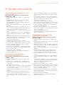
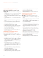
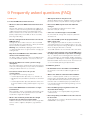
Contents
1 Introduction
04
4 Additional properties of dimmable control gears
1.1 Dimmable lighting installations
04
from OSRAM
1.1.1 Economy
04
4.1 OSRAM DALI/1…10 V-ECGs: Added value through intelligent
1.1.2 Light comfort
04
features
20
1.1.3 Reliability/Safety
05
4.2 OSRAM DALI ECG and Touch DIM interface
21
1.1.4 The right control unit for every application
05
4.2.1 Setting Touch DIM Function parameters
21
4.2.2 Automatic lamp switch-off at suffi cient light level
21
22
20
2 Overview of dimmable control gears
06
4.2.3 Wiring and cable compensation
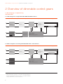
2.1 Block diagrams of a digital/analog dimmable ECGs
06
4.2.3.1 Operating parameters for Touch DIM and Corridor
2.1.1 Block diagram of a digital dimmable ECG with DALI interface
06
functionality
23
4.2.3.2 Interference compensation (for wiring > 25 m)
23
24
2.1.2 Block diagram of an analog dimmable ECG with
1…10-V interface
06
4.2.4 Touch DIM operation
2.2 DALI in comparison to 1…10 V and KNX/LON
07
4.2.5 Operating modes with Touch DIM
24
2.2.1 DALI and 1…10-V properties
07
4.2.6 Asynchronism
24
2.3 Installation and wiring instructions for dimmable
luminaires/lighting installations
08
2.3.1 Burn-in instructions, wire insulation
4.2.7 Synchronization
24
4.2.8 Avoiding asynchronisms: DALI repeater
25
4.2.9 Behavior after power voltage disruption
25
and voltage loads
08
4.3 OSRAM DALI ECGs in emergency lighting applications (EL –
2.3.2 Safety and installation instructions
08
Emergency Lighting)
2.3.3 Wiring instructions for dimmable luminaires –
suppression of radio interference
25
4.3.1 Power failure in sub-distributor (SD)
08
2.3.4 Wiring instructions for dimmable luminaires
general illumination
26
4.3.2 DC emergency lighting operation in the event of
when operating multiple ECGs in a luminaire
09
power failure in main distributor (MD) ➔ battery operation
2.3.5 Wiring examples for dimmable control gears
10
4.3.3 DC emergency lighting operation without additional
2.4 The DALI interface – technical details
12
external monitoring module (e.g.: CEAG 2L-CG-SB) by
2.4.1 Simplifi ed installation
12
shutting down the DALI control units
2.4.2 Construction site operation
12
4.3.4 Advantages of OSRAM DALI control gears in
2.4.3 Advantages of DALI ECG with group assignment
12
emergency lighting applications
2.4.4 Integrated scene memory
12
4.4 OSRAM DALI magic and OSRAM DALI Wizard
27
2.4.5 ECG status report
12
4.5 Basic circuits in 1…10-V control gears
28
2.4.6 Switching relay no longer necessary
12
4.5.1 “Standby” operating modes with the 1…10-V interface
28
2.4.7 Addressing is not a must
12
4.5.1.1 Applications
28
2.4.8 The DALI system principle
12
4.5.1.2 Control via analog output
30
2.4.9 The DALI topology
12
4.5.1.3 Matching circuit
30
2.4.10 DALI parameters in the ECG
13
4.5.1.4 Control via KNX
30
2.4.11 Transmission wire requirements
13
4.6 Special circuit diagrams, tips and tricks for the
2.4.12 Connection diagram for the DALI ECGs
13
1…10-V interface
2.4.13 DALI data transmission
14
4.6.1 Temperature-dependent control
30
2.4.14 Behavior in the event of failure
14
4.6.2 Limiting top and bottom control voltage
30
2.5 The DALI dimming curve
14
4.6.3 Line length of the 1…10-V control line
31
2.5.1 Logarithmic dimming curve
14
4.6.4 1…10-V DIM ECGs and emergency lighting
31
2.5.2 Linear dimming curve
14
4.7 Terminals/cable cross sections/wire stripping
31
4.7.1 Pressing in and loosening the connection cables
32
32
2.6 Features and performance characteristics
26
26
27
30
of the digital interface
15
4.7.2 Cable cross sections
2.7 Properties of the 1…10-V interface
15
4.7.3 Basic insulation
32
2.7.1 The 1…10-V dimming curve
16
4.7.4 Sockets
32
4.7.5 Master/slave circuit
32
3 New properties of QTi DALI
17
4.7.6 Minimum refl ector distances
32
3.1 Corridor Function and parametrization options
17
4.8 Temperature behavior of dimmable ECGs from OSRAM
33
3.1.1 Description
17
4.8.1 Intelligent thermal management allows operation
3.1.2 Activating the Corridor Function
18
in a wide ambient temperature range through
3.1.3 Changing from the Corridor Function
power reduction control
33
18
4.8.2 Color temperature
35
3.1.4 Setting Corridor Function parameters
18
4.8.3 Outdoor applications
35
3.2 Touch DIM Function
18
4.8.4 Functional testing for luminaires
35
3.3 Emergency lighting: DC voltage detection, EL (optional)
19
4.9 Dimming amalgam lamps with OSRAM ECGs
36
3.4 SMART GRID and management
19
4.9.1 Falling below the min. dimmer setting at low temperatures
37
3.5 POWER2LAMP power matching (optional)
19
4.9.2 The advantages of amalgam technology
37
to the Touch DIM Function
2