1
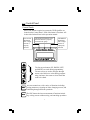
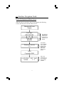
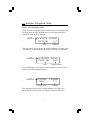
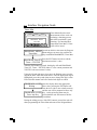
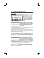
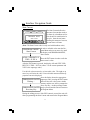
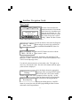
TS III
Qualifier
Operation Manual
ASG, Division of Jergens Inc.
Jergens Way
15700 S. Waterloo Road
Cleveland, OH 44110-3898
Tel: (216) 486-6163
Toll-Free: (888) 486-6163
Fax: (216) 481-4519
E-mail: [email protected]
www.asg-jergens.com
Table of Contents
INTRODUCTION .............................................................................................................. 3
CONFIGURATION ............................................................................................................. 3
WARNINGS & CAUTIONS..........................................................................................4-5
QUICK START GUIDE.................................................................................................6-7
CONTROL PANEL .......................................................................................................8-9
CONNECTION PROCEDURE...................................................................................... 10
INTERFACE NAVIGATION GUIDE .....................................................................11-37
POWER UP SEQUENCE .................................................................................................. 11
HOME SCREEN ..........................................................................................................12-14
BASIC OPERATIONS ...................................................................................................... 15
Reset Batch ............................................................................................................. 15
ADVANCED OPERATIONS .........................................................................................16-37
Password & Keyswitch .......................................................................................... 16
Program Menu ..................................................................................................17-18
AutoCal Procedure...........................................................................................19-20
Timer Min ............................................................................................................... 21
Timer Max .............................................................................................................. 22
Timer Bump ............................................................................................................ 23
Start Current .......................................................................................................... 24
Min Current............................................................................................................ 25
Max Current ........................................................................................................... 26
Batch Count............................................................................................................ 27
Globalize ................................................................................................................ 28
Relay & Beep.......................................................................................................... 29
Parameter Select .................................................................................................... 30
Count Direction...................................................................................................... 31
New Password ........................................................................................................ 32
Digital Inputs.......................................................................................................... 33
Current Draw ......................................................................................................... 34
View Run Time ....................................................................................................... 35
View Shutoff I ......................................................................................................... 36
LCD Contrast ......................................................................................................... 37
SOFTWARE (CYBER QUALIFIER) ......................................................................38-39
OPERATIONS GRAPHS...........................................................................................40-44
SPECIFICATIONS.....................................................................................................45-46
I/O SPECIFICATIONS ...................................................................................................... 46
TROUBLESHOOTING .............................................................................................47-48
INDEX ..........................................................................................................................49-51
Introduction
Thank you for purchasing ASG’s TS III Qualifier. The following
sections describe WARNINGS and CAUTIONS for using our product. Make sure to read these sections before using the TS III Qualifier. As with any electrical product, mishandling the TS III Qualifier could cause damage to the TS III component or cause physical
injury to the individual. Proper care must be used at all time when
operating or servicing the TS III Qualifier. In addition to these sections, carefully read the Set-up Procedure and Interface Navigation
Guide to ensure proper usage.
The Interface Navigation Guide is broken down into sections: controls that are accessible while the TS III Qualifier is Locked
(Advance Operations), and Unlocked (Basic Operations).
This operation manual is designed for both the BL and CL style TS
III Qualifiers. Throughout this manual all features are included in
both models unless noted otherwise.
This operation manual is designed for the general operation of the
TS III Qualifier. If any additional questions or concerns should
arise, please contact your local ASG representative.
Please check parts prior to use. If anything is missing or damaged,
contact your local ASG representative.
Configuration
TS III Qualifier…...………………………………………One Piece
Power Cord……...………………………………………..One Piece
Keys………….…...………………………………………Two Keys
Operation Manual………………………………………...One Copy
3
Warning
Make sure to read this section
If these instructions are ignored, and the product is handled inappropriately, serious injury could occur.
Whenever disassembling the unit make sure power has
been turned off and the power cord is removed from the
outlet. There is a high electrical voltage inside the unit
that could cause an electric shock, failure, or fire.
If you have not worked on or are not familiar with electrical components having a transformer and printed circuit
boards we suggest that you return the TS III Qualifier directly to ASG for service, modification or changeover.
If an abnormal odor, unusual sound or smoke is observed,
stop using the product, unplug it immediately and contact
your ASG representative.
Do not allow any type of liquid to come in contact with
any part of the unit, because it could result in an electrical
shock or fire.
Fully insert all plugs into their proper receptacle. Insufficient contact may generate heat that could result in a fire
or electrical shock.
Do not fold, bend, or impose excessive force on the cord.
Excessive force on the cord may cause a short-circuit,
which could result in a fire or electrical shock.
While inserting or removing the plugs don’t pull on the
cords. This action could result in a disconnection or a
broken plug. Make sure to hold the plug body during
insertion and removal.
4
Cautions
If these instructions are ignored and the product is handled inappropriately, bodily injury or property damage could occur.
•
This unit accepts an AC input voltage from 100VAC to
240VAC. Trying to operate this unit with a voltage outside
that range may cause damage to the unit.
•
Do not place the product in an unstable location. Dropping
the unit could result in damage to the TS III Qualifier.
•
Do not place or store the unit in a location with moisture or
dust, to prevent possible fire or failure.
•
When moving the TS III Qualifier, make sure to turn OFF the
power and remove the power plugs.
•
Before maintenance, make sure to turn OFF the power and
remove the power plugs.
•
There are no user serviceable parts inside the main enclosure
of the TS-III Qualifier.
•
As with any printed circuit boards proper care and knowledge
is critical if a customer attempts to service the TS III unit.
Damage occurring to the electrical components by the customer attempting to service the unit voids all warranties and
all work performed is the sole responsibility of the customer.
5
Quick Start Guide
Warning:
Make sure to review the WARNINGS and CAUTIONS sections
located on pages 4 and 5 before using the TS III Qualifier.
CYCLE
BATCH
REJECT
TOOL TYPE
BRUSHLESS
ENT
ESC
Step 1:
Power up the unit waiting for the Home Screen (See pages 11-14) to
appear. During power-up the device will identify the tool type for
which the unit is configured (either BRUSH or BRUSHLESS). Be
sure that the tool to be used with this device matches the tool type.
- TS-III BL Qualifier, Part Number - 66517
- TS-III CL Qualifier, Part Number - 66515
Step 2:
Attach one end the cord to the tool and the other end to the TS III
Qualifier tightening the knurled knob. Select the desired tool speed
(HI or LO). Turn the Soft Start either ON or OFF (Note: The Soft
Start only work with brush style tools).
CYCLE
BATCH
REJECT
ENTER PASSWORD
* * * *
ENT
ESC
Step 3:
Press the enter (ENT) button and enter the Programming Menu. Either
use the Arrow keys to insert password (0104 default) or bypass the
password by turning the key to the programming position (Horizontal).
Continued on the next page….
6
Quick Start Guide
CYCLE
BATCH
Step 4:
Use the arrow keys to navigate to
the AutoCal option in the Program Menu. Once at the AutoCal option, press the enter (ENT)
button to select it.
REJECT
PROGRAM MENU
AutoCal
ENT
ESC
Step 5:
The unit will prompt the operator (B-LESS or BRUSH) TOOL OFF
Press ENT Key. Make sure the tool is not running and press the ENT
Key. The unit will count down 5s..thru..1s compensating for any
background noise and automatically advances to the next screen.
Step 6:
After the count down is finished the display will prompt the user to
run a fastener, the display should read ACAL (either B-LESS or
BRUSH) TOOL Run Fastener. Run the tool on the target fastener allowing the clutch to turn the tool off. After the clutch fires, the display should read AUTOCAL COMPLETE Press Any Key.
If a successful run down is not completed the user will not advance to
the next screen. Another target fastener should be run again allowing
the tool clutch to turn the tool off.
After AUTOCAL COMPLETE Press Any Key is displayed, pressing
a key will return the operator to the Program Menu.
Step 7:
Any of the Advanced Operations can be adjusted including: Timer
Bump, Batch Count, Count Direction, etc. (See pages 16-37)
Step 8:
When finished editing parameters press the ESC button to lock the
unit and return to the Display/Run Screen.
Step 9:
Run several fasteners to ensure that the unit is working properly. If
everything appears to be working, production can begin.
7
Control Panel
Control Panel:
Most of the buttons required to operate the TS III Qualifier are
located on the Control Panel. Each of the button’s functions will
be described in detail later in this operation manual.
The CYCLE
illuminates
after a single
fastener is
properly
inserted.
The BATCH illuminates after
the final fastener is properly
inserted in the group.
CYCLE
BATCH
The REJECT
illuminates
after a single
fastener is
improperly
inserted.
REJECT
LCD
DISPLAY
ENT
ESC
The four arrow buttons (UP, DOWN, LEFT,
and RIGHT) are used during programming.
The arrow keys are used to navigate through
menus, raise and lower values during programming, and move the cursor to select items that
need to be edited.
The ENT button has a wide variety of functions including:
ENT saving parameters, selecting an items, changing screens, and
continuing through different operations.
ESC
The ESC button also has an assortment of functions including: exiting screens without saving, and canceling operations.
8
Control Panel
Front Panel:
Soft Start
Speed
ON
REJECT
OFF
HI
Tool
LO
The five pin circular connector is used
to supply power to a tool and also to
read signals back from the tool.
The Soft Start switch turns the Soft
Start feature ON and OFF. If the Soft
Output 30/20 VDC
Start feature is enabled, the tool will
spin slowly for a revolution or two before increasing to full speed.
(Note: Can only be enabled with brush tools.)
ENT
ESC
Tool speed is governed by the Speed switch. When this switch is in
the HI setting, the VDC out will be 30VDC. On the LO setting, the
power supply provides 20VDC. The tool’s speed is directly proportional to output voltage. (Refer to the ASG catalog for tool speeds)
Rear Panel:
Keyswitch
Beeper
RS-232
I/O Connector
AC Input and
Main Power Switch
The main power switch for the unit and the power entry module are
found on the rear panel. This unit is capable of running on an AC
input voltage of 100VAC to 240VAC.
The keyswitch allows a user to reach the programmable functions
without entering a password.
The unit’s beeper provides audible feedback when rejects occur and
can provide a double –beep when a batch accept occurs (See page
29).
The RS-232 port can be used as a secondary means of programming
the unit or getting information from the unit. (See page 45 - 48)
The 12 Pin I/O Connector contains several input and output functions. (See page 46 for more details)
9
Connection Procedure
Connection Procedure
The following are general guidelines for connecting the TS III
Qualifier. Specific programming instructions are described in the
Interface Navigation Guide. (See pages 11-37)
1. Plug the tools power cord into the rear of the electric screwdriver
and then the front of the TS III Qualifier.
2. Plug the AC cord into the rear of the TS III Qualifier and then into
the wall.
3. Verify that all connections are secure.
4. Flip the Qualifier’s main power switch to the ON position.
5. The unit should begin the Power Up Sequence (See page 11).
6. When the TS III Qualifier brings up the Home Screen (See page
12-14), it is ready for programming.
10
Interface Navigation Guide
Power-Up Sequence & Home Screen
When the unit is powered up, the LCD will display the following
screens and then proceed to the Home Screen.
Monitored Power
Supply
Tool Type
BRUSHLESS
OR
Tool Type
BRUSH
Firmware Version
1.5
}
Pay special attention to this
screen so you
know how your
qualifier is configured.
}
The firmware
version installed
in your TS-III
Qualifier is displayed at this
point in the
Power-Up Sequence.
ASG
Copyright 2004
A: STATUS
NONE
CNT / BAT
2/3
11
}
This is your
home screen. It
will be displayed
during normal
operation
Interface Navigation Guide
Home Screen/Display Panel
There are three screens associated with the home screen/ display panel.
Pressing either the UP or DOWN arrow keys will allow the user to
change the view on the LCD screen.
Current
Parameter Set
A: STATUS CNT/BAT
CYCLE OK
1/3
Status
Count/Batch
The first of these screens shows the current parameter set, status of the
last fastening, current count and the number of fasteners in the batch.
Current
Parameter Set
A: STATUS TOTAL
CYCLE OK
30212
Status
Completed Batches
The second display screen shows current parameter set, status of last
fastener, and total completed batches.
Current
Parameter Set
A: TOTAL
30212
CNT/BAT
1/3
Completed Batches
Count/Batch
The third display screen shows current parameter set, total completed batches, current count, and number of fasteners in a batch.
12
Interface Navigation Guide
Home Screen/Display Panel
The following displays will appear while the unit is in production.
A: STATUS
NONE
CNT / BAT
0/3
A: STATUS CNT / BAT
IN CYCLE
0/3
A: STATUS CNT / BAT
CYCLE OK
2/3
A: STATUS CNT / BAT
BATCH OK
3/3
}
View while waiting
for production to
begin
}
View during rundown
(in-cycle)
}
ACCEPT Statuses
Cyc Acc: indicates that the previous rundown was successful. A
successful rundown will increase the count and fire the Accept
light.
Bat Acc: indicates the previous Batch has been completed and accepted. A complete batch will be accompanied by a double beep
along with the Batch light illuminating.
13
Interface Navigation Guide
Home Screen/Display Panel
The following displays will appear while the unit is in production
and an error/reject is generated.
A: STATUS CNT / BAT
REJ TMin
1/3
REJECTS will be described by their corresponding message.
A: STATUS CNT / BAT
REJ TMax
1/3
A: STATUS CNT / BAT
REJ TClu
1/3
Tmin: The tool was unable to run long enough to satisfy the
minimum time parameter.
Tmax: The tool passed the maximum time parameter.
Tclu: The tool’s clutch did not engage.
A: STATUS CNT / BAT
REJ IMin
1/3
A: STATUS CNT / BAT
REJ IMax
1/3
}
REJECTS will be described by their corresponding message.
IMin: The tool was unable to draw enough current to satisfy the
minimum current parameter when the clutch engaged.
IMax: The tool passed the maximum current parameter when the
clutch engaged.
Note: Brushless tools only.
14
Interface Navigation Guide
Basic Operations
The following features are only active while the TS III Qualifier is
in the locked position.
Reset Batch
The Reset Batch will clear the value in the count, resetting it to zero.
A: STATUS
NONE
CNT / BAT In order to reset the batch the operator must be 0n the Home Screen.
2/3
RESET
BATCH
ENT = YES ESC = NO
Press the ESC button in order to reset
the batch count.
After the ESC button is pressed, the
display will read RESET BATCH, ENT=YES ESC=NO.
Use the ENT button to confirm the batch clear and the ESC button
to cancel this operation.
After either button is pressed the operator will automatically return
to the Home Screen.
Change Parameter
The Parameter can be changed through the Keypad or Remotely
through the I/O. This section only describes changing the parameter
with the Keypad. (Note: This function must be enabled in the Program Menu; see page 30 for changing the Parameter Select (Keypad
or Remote I/O).
A: STATUS
NONE
CNT / BAT In order to change the parameter the
operator must be on the Home Screen.
0/3
B: STATUS
NONE
Pressing either the left or right arrow
CNT / BAT key the operator will scroll through the
eight different parameter options.
0/3
After changing the parameter the operator will be immediately ready
to run under the new parameter that is selected.
15
Interface Navigation Guide
Advanced Operations
The features listed in the Advanced Operation section of this manual are only accessible while the unit is unlocked. The operator
must unlock the unit through one of the two following methods.
Password (Default 0104)
CYCLE
BATCH
Press the ENT key to access the
Program Menu. After pressing the
ENT button the operator will be
prompted to Enter a Password to
gain access to the Program Menu
and the advanced operations.
REJECT
ENTER PASSWORD
0***
ENT
ESC
Using the left and right arrow keys move the flashing cursor over the
asterisk in the password that needs changed. Once the cursor is over the
appropriate asterisk the current number in that position will be viewed.
Adjust the digit to the proper password with the up and down arrows.
Proceed in this manner until all of the desired digits are edited. The default password that ships with all unit is 0104.
After all of the proper digits have been inserted press the ENT key to
gain access to the Program Menu
The unit can be locked again by pressing the ESC key.
Keyswitch:
Press the ENT key to access the
Program Menu. After pressing the
ENT button the operator will be
prompted to Enter a Password to
gain access to the Program Menu
and the advanced operations.
Keyswitch
Insert the key into the key hole located in the rear of the unit and turn it
to the horizontal position. If the keyswitch remains in the horizontal
position the Program Menu can be accessed even if the key is removed.
The unit can be locked again by turning the key to the vertical position
and pressing the ESC key.
16
Interface Navigation Guide
Advanced Operations
The following features are available only while the unit is unlocked.
Program Menu
ENT
The following is a listing of all options located in the
Programming Menu. While in the Program Menu:
- Arrows (ALL): advances operator to the next or previous option in the menu
- ENT: select the displayed option
- ESC: exit the menu
PROGRAM MENU
AutoCal
See page 19-20 for
more information
PROGRAM MENU
Timer Min
See page 21 for
more information
PROGRAM MENU
Timer Max
See page 22 for
more information
PROGRAM MENU
Timer Bump
See page 23 for
more information
PROGRAM MENU
Start Current
See page 24 for
more information
PROGRAM MENU
Min Current
See page 25 for
more information
PROGRAM MENU
Max Current
See page 26 for
more information
Continued on the next page….
17
Interface Navigation Guide
Program Select Continued From Previous Page
PROGRAM MENU
Batch Count
See page 27 for
more information
PROGRAM MENU
Globalize
See page 28 for
more information
PROGRAM MENU
Relay & Beep
See page 29 for
more information
PROGRAM MENU
Parameter Select
See page 30 for
more information
PROGRAM MENU
Count Direction
See page 31 for
more information
PROGRAM MENU
New Password
See page 32 for
more information
PROGRAM MENU
Digital Inputs
See page 33 for
more information
PROGRAM MENU
Current Draw
See page 34 for
more information
PROGRAM MENU
View Run Time
See page 35 for
more information
PROGRAM MENU
View Shutoff I
See page 36 for
more information
PROGRAM MENU
LCD Contrast
See page 37 for
more information
18
Interface Navigation Guide
AutoCalTM Procedure
The AutoCalTM is the first option in
the Program Menu and is used to
quickly set-up specific parameters
PROGRAM MENU
including Timer Min, Timer Max,
AutoCal
and Start Current. The user runs a
sample fastener and allows the TS
ENT ESC
III Qualifier to review the rundown
and automatically set the parameter based on that sample fastener. The
following steps will walk the operator through the calibration process.
CYCLE
BATCH
REJECT
PROGRAM MENU
AutoCal
In order to perform an AutoCal enter the
Program Menu and press an arrow key
until the display reads PROGRAM
MENU, AutoCal.
Press the ENT button to perform an
AutoCal.
B-LESS TOOL OFF When the screen reads (either B-LESS or
BRUSH) TOOL OFF, Press ENT Key,
Press ENT Key
the driver must not be running. The operator should not turn OFF the main power switch or disconnect
power to the driver.
Pressing the ENT key is your confirmation that to tool is not running.
ACAL BACKGROUND After the ENT button is pressed, the display will read ACAL BACKGROUND
Time Ys I = X.X
Time Ys, I = X.X (where Y is a countdown is seconds 5s...4s...3s…2s….1s...and X.X is the background
noise that is being compensated).
After all background noise is eliminated the operator will be automatically advanced to the next screen.
Continued on the next page….
19
Interface Navigation Guide
Auto Calibration Continued
Following the unit elimination
of background noise the TS III
Qualifier will automatically
ACAL B-LESS TOOL
advance to the next screen and
Run Fastener
should display ACAL (either
BRUSH or B-LESS) TOOL,
ENT ESC
Run Fastener. Be sure that the
right type of tool is being used with the unit before proceeding.
CYCLE
BATCH
REJECT
The operator will need to rundown the target fastener. The target
fastener must match all of the required specifications, because all of
the parameter will be based off of the most recent rundown, i.e. the
target fasteners. Once the unit witnesses the clutch stopping, all of
the timers and threshold will automatically be calculated and stored
to non-volatile memory for the parameter set that the unit was in at
the beginning of the process.
Automatically following a successful rundown, the profile from the
previous sample rundown is loaded. The profile from this sample
fastener creates the Timer Min, Timer Max, Start Current and inserts
the default into all of the other remaining parameters.
While this data is being stored, the dis-
AUTOCAL COMPLETE play will read AUTOCAL COMWriting….
PLETE, Writing…. Once the variables
are stored, the display will read AUTOCAL COMPLETE, Press
Any Key. Pressing a key at this point
AUTOCAL COMPLETE will return the unit to the Programming
Press Any Key
Menu.
The ESC key can be pressed at any time during this process to abort
the ACAL setup and return to the Program Menu without changing
the parameter data.
Note: If the AutoCal is not working properly please review the Troubleshooting section located on a page 47-48.
20
Interface Navigation Guide
Timer Min
CYCLE
BATCH
Timer Min defines the minimum
amount of time a tool has to run
during a fastening process in order to be considered a good fastening. If a fastening process is
shorter than Timer Min, a Tmin
reject will be issued.
REJECT
PROGRAM MENU
Timer Min
ENT
ESC
PROGRAM MENU In order to edit this value enter the Program
Menu and press an arrow key until the disTimer Min
play reads PROGRAM MENU, Timer Min.
PROGRAM Tmin P:Y Press the ENT button in order to edit the
minimum run timer’s value.
Timer = XX.XXX
After the ENT button is pressed, the display will read PROGRAM
Tmin P:Y, Timer = XX.XXX (where Y is the current parameter and
XX.XXX is the current timer’s value).
Using the left and right arrow keys move the flashing cursor over the
digit in the timer value that needs edited. Once the appropriate digit is
highlighted, press the up and down arrows to change the digit’s value.
Proceed in this manner until all of the desired digits are edited.
TIMER MIN SAVED Once the display shows the appropriate
timer value, pressing the ENT button will
Writing….
store the new value to non-volatile memory
and the user will be prompted to Press Any
Key. At this point any button may be
TIMER MIN SAVED pressed and the unit will return to the ProPress Any Key
gram Menu.
During the editing process, if the ESC button is pressed, the unit will
abort programming the Timer Min and return to the Program Menu.
21
Interface Navigation Guide
Timer Max
CYCLE
BATCH
Timer Max defines the maximum amount of time a tool can
run during a fastening process
and still be considered a good
fastening. If a fastening takes
longer than Timer Max, a Tmax
reject will be issued.
REJECT
PROGRAM MENU
Timer Max
ENT
ESC
PROGRAM MENU In order to edit this value enter the Program
Menu and press an arrow key until the disTimer Max
play reads PROGRAM MENU, Timer Max.
PROGRAM Tmax P:Y Press the ENT button in order to edit the
maximum run timer’s value.
Timer = XX.XXX
After the ENT button is pressed, the display will read PROGRAM
Tmax P:Y, Timer = XX.XXX (where Y is the current parameter and
XX.XXX is the current timer’s value).
Using the left and right arrow keys move the flashing cursor over the
digit in the timer value that needs edited. Once the appropriate digit is
highlighted, press the up and down arrows to change the digit’s value.
Proceed in this manner until all of the desired digits are edited.
TIMER MIN SAVED Once the display shows the appropriate
timer value, pressing the ENT button will
Writing….
store the new value to non-volatile memory
and the user will be prompted to Press Any
TIMER MIN SAVED Key. At this point any button may be
pressed and the unit will return to the ProPress Any Key
gram Menu.
During the editing process, if the ESC button is pressed, the unit will
abort programming the Timer Max and return to the Program Menu.
22
Interface Navigation Guide
Timer Bump
CYCLE
BATCH
Timer Bump defines an amount
of time that a tool can run and
that run will be ignored if the
clutch does not fire (i.e. torque is
not achieved). This timer may
be used to eliminate nuisance
rejects.
REJECT
PROGRAM MENU
Timer Bump
ENT
PROGRAM MENU
Timer Bump
ESC
In order to edit this value enter the Program Menu and press an arrow key until
the display reads PROGRAM MENU,
Timer Bump.
PROGRAM Tbmp P:Y Press the ENT button in order to edit the
Timer = XX.XXX
bump timer’s value.
After the ENT button is pressed, the display will read PROGRAM
Tbmp P:Y, Timer = XX.XXX (where Y is the current parameter and
XX.XXX is the current timer’s value).
Using the left and right arrow keys move the flashing cursor over the
digit in the timer value that needs edited. Once the appropriate digit is
highlighted, press the up and down arrows to change the digit’s value.
Proceed in this manner until all of the desired digits are edited.
TIMER BUMP SAVED Once the display shows the appropriate
timer value, pressing the ENT button will
Writing….
store the new value to non-volatile memory and the user will be prompted to Press Any Key. At this point any
button may be pressed and the unit will
TIMER BUMP SAVED return to the Program Menu.
Press Any Key
During the editing process, if the ESC
button is pressed, the unit will abort programming the Timer Bump
and return to the Program Menu.
23
Interface Navigation Guide
Start Current
CYCLE
BATCH
The Start Current defines the
amount of current that needs to
be drawn by a brushless tool before the unit is considered to be
in cycle. Once the tool starts
drawing this amount of current,
the run-timers will start.
REJECT
PROGRAM MENU
Start Current
ENT
ESC
(Note: The Start Current value is only used with brushless tools.)
PROGRAM MENU
Start Current
In order to edit this value enter the Program Menu and press an arrow key until
the display reads PROGRAM MENU,
Start Current.
STRT CURRENT P:Y Press the ENT button in order to edit the
TRIP = X.XX A
start current’s value.
After the ENT button is pressed, the display will read STRT CURRENT P:Y, TRIP = X.XX A (where Y is the current parameter and
X.XX is the amperage value).
Use the left or down arrow key to lower this value. The right or up
arrow keys will raise the value. Proceed in this manner until the appropriate current is displayed.
Once the display shows the appropriate
THRESHOLD SAVED amperage value, pressing the ENT button
Writing….
will store the new value to non-volatile
memory and the user will be prompted to
Press Any Key. At this point any button
THRESHOLD SAVED may be pressed and the unit will return to
the Program Menu.
Press Any Key
During the editing process, if the ESC button is pressed, the unit will
abort programming the Start Current and return to the Program Menu.
24
Interface Navigation Guide
Min Current
The Min Current defines the
minimum amount of current that
needs to be drawn by a brushless
PROGRAM MENU
tool when the tools clutch enMin Current
gages. This threshold can be
used as a secondary check for the
ENT ESC
tool’s clutch setting. (Note: The
Min Current value is only used with brushless tools.)
CYCLE
BATCH
REJECT
In order to edit this value enter the Program
PROGRAM MENU Menu and press an arrow key until the disMin Current
play reads PROGRAM MENU, Shut-Off
Current.
MIN CRNT P:Y
TRIP = X.XX A
Press the ENT button in order to edit the
Min Current’s value.
After the ENT button is pressed, the display will read MIN CRNT
P:Y, TRIP = X.XX A (where Y is the current parameter and X.XX is
the amperage value).
Use the left or down arrow key to lower this value. The right or up
arrow key will raise the value. Proceed in this manner until the appropriate current is displayed.
THRESHOLD SAVED Once the display shows the appropriate
amperage value, pressing the ENT button
Writing….
will store the new value to non-volatile
memory and the user will be prompted to Press Any Key. At this
point any button may be pressed and the
THRESHOLD SAVED unit will return to the Program Menu.
Press Any Key
During the editing process, if the ESC
button is pressed, the unit will abort programming the Min Current
and return to the Program Menu.
25
Interface Navigation Guide
Max Current
The Max Current defines the
maximum amount of current that
can be drawn by a brushless tool
PROGRAM MENU
when the tool clutches out. This
Max Current
threshold can be used as a secondary check for the tool’s clutch
ENT ESC
setting. (Note: The Max Current
value is only used with brushless tools.)
CYCLE
BATCH
REJECT
PROGRAM MENU In order to edit this value enter the Program
Menu and press an arrow key until the disMax Current
play reads PROGRAM MENU, Max Current.
MAX CURRENT P:Y Press the ENT button in order to edit the
TRIP = XX.XX A max current’s value.
After the ENT button is pressed, the display will read MAX CURRENT P:Y, TRIP = XX.XX A (where Y is the current parameter and
XX.XX is the amperage value).
Use the left or down arrow key to lower this value. The right or up
arrow key will raise the value. Proceed in this manner until the appropriate current is displayed.
Once the display shows the appropriate
THRESHOLD SAVED amperage value, pressing the ENT button
Writing….
will store the new value to non-volatile
memory and the user will be prompted to Press Any Key. At this
point any button may be pressed and the
THRESHOLD SAVED unit will return to the Program Menu.
Press Any Key
During the editing process, if the ESC
button is pressed, the unit will abort programming the Max Current
and return to the Program Menu.
26
Interface Navigation Guide
Batch Count
CYCLE
BATCH
The Batch Count is typically
programmed to be the number of
fasteners in a given assembly. A
Cycle Accept signal will be generated each time a proper fastening occurs. A Batch Accept
however, will occur when the
REJECT
PROGRAM MENU
Batch Count
ENT
ESC
count reaches the batch value.
In order to edit this value enter the Program
PROGRAM MENU Menu and press an arrow key until the disBatch Count
play reads PROGRAM MENU, Batch
Count.
Batch Count P:Y
Batch = XXX
Press the ENT button in order to edit the
batch count’s value.
After the ENT button is pressed, the display will read BATCH
COUNT P:Y, Batch = XXX (where Y is the current parameter and
XXX is the number of fasteners in a batch).
Use the up or down arrow key to raise or lower the batch value by 1.
The left and right arrow keys will raise or lower the value by 10. Proceed in this manner until the appropriate batch value is displayed.
Once the display shows the appropriate
batch, pressing the ENT button will store
the new value to non-volatile memory and
the user will be prompted to Press Any Key. At this point any button
may be pressed and the unit will return to
BATCH SAVED
the Program Menu.
BATCH SAVED
Writing….
Press Any Key
During the editing process, if the ESC button is pressed, the unit will abort programming the Batch Count and
return to the Program Menu.
27
Interface Navigation Guide
Globalize
Often, when multiple parameter
sets are used, only one or two
variables within the parameter
PROGRAM MENU
sets needs to vary. It’s very
Globalize
common to have everything
within multiple parameter sets be
ENT ESC
identical except for a variation in
the batch count. If this is the case, globalizing a parameter set may
help to speed up the programming process. When globilization is
used a parameter set is copied to all of the other parameters.
CYCLE
BATCH
REJECT
In order to Globalize all parameters enter
PROGRAM MENU the Program Menu and press an arrow key
Globalize
until the display reads PROGRAM MENU,
Globalize.
GLOBALIZE PARAM Press the ENT button in order to select a
parameter to be globalized.
Parameter = Y
After the ENT button is pressed, the display will read GLOBALIZE
PARAM, Parameter = Y (where Y is the parameter that will be copied to all other parameters if selected).
Using the arrow keys select the parameter set to be copied.
Once the display shows the appropriate
GLOBALIZE PARAM parameter, pressing the ENT key will
Writing….
copy that parameter to all of the other parameters and the user will be prompted to Press Any Key. At this
point any button may be pressed and the
GLOBALIZE SAVED unit will return to the Program Menu.
Press Any Key
During the editing process, if the ESC
button is pressed, the unit will abort programming the Globilization
and return to the Program Menu.
28
Interface Navigation Guide
Relay & Beep
The output relays in this system
can be programmed to be either
momentary or latching. If the
PROGRAM MENU
relays are momentary they will
Relay & Beep
close briefly (200ms) when and
event occurs. When set to latchENT ESC
ing, the relay closes and remains
that way until the tool starts running again.
CYCLE
BATCH
REJECT
The beeper in this system can be programmed to double-beep when a
batch accept occurs.
PROGRAM MENU
Relay & Beep
In order to edit these items enter the Program Menu and press an arrow key until
the display reads PROGRAM MENU,
Relay & Beep.
PGM RELAY/BEEPER Press the ENT button in order to edit relay
RLY XXX BEEP YYY or beeper settings.
After the ENT button is pressed, the display will read PGM RELAY/
BEEPER, RLY XXX BEEP YYY (where XXX is either MOM for
momentary or LAT for latching and YYY is either ON or OFF).
Using the arrow keys set the desired relay and beeper setting.
RLY/BEEPER SAVED Once the display shows the appropriate
settings, pressing ENT will save the setWriting….
tings to non-volatile memory and the user
will be prompted to Press Any Key. At
RLY/BEEPER SAVED this point any button may be pressed and
the unit will return to the Program Menu.
Press Any Key
During the editing process, if the ESC button is pressed, the unit will
abort programming the Relay & Beeper and return to the Program
Menu.
29
Interface Navigation Guide
Parameter Select
CYCLE
BATCH
This unit can be programmed to
change parameter either through
the keypad or remotely through
the I/O.
REJECT
PROGRAM MENU
Parameter Select
ENT
PROGRAM MENU
Parameter Select
ESC
In order to edit this function, enter the
Program Menu and press an arrow key
until the display reads PROGRAM
MENU, Parameter Select.
PARAMETER SELECT
Press the ENT button in order to edit the
Remote I/O
Parameter Select.
After the ENT button is pressed, the display will read PARAMETER
SELECT (Keypad or Remote I/O).
Using the arrow keys set the desired parameter select (either Keypad
or Remote I/O). The Keypad option will allow the operator to change
the parameter with the left and right arrow keys from the home screen
while the unit is in the locked position. (See page 15 for more information on the Keypad.) The Remote I/O option will allow the parameter to be switched only through the I/O. (See page 45 - 46 for more
information on the Remote I/O)
Once the display shows the appropriate setting, pressing ENT will save the settings to
non-volatile memory and the user will be
prompted to Press Any Key. At this point
DIRECTION SAVED any button may be pressed and the unit will
return to the Program Menu.
Press Any Key
Parameter Select
Writing….
During the editing process, if the ESC button is pressed, the unit will
abort programming the Parameter Select and return to the Program
Menu.
30
Interface Navigation Guide
Count Direction
CYCLE
BATCH
This unit can be programmed to
count up from zero until the
batch is reached or count down
to zero.
REJECT
PROGRAM MENU
Count Direction
ENT
ESC
In order to edit this function, enter the Pro-
PROGRAM MENU gram Menu and press an arrow key until the
Count Direction
display reads PROGRAM MENU, Count
Direction.
COUNT DIRECTION Press the ENT button in order to edit the
Count Direction.
Count = XXX
After the ENT button is pressed, the display will read COUNT DIRECTION, Count XXX (where XXX is either UP or DOWN).
Using the arrow keys set the desired count direction (either up or
down) .
COUNT DIRECTION Once the display shows the appropriate setting, pressing ENT will save the settings to
Writing….
non-volatile memory and the user will be
prompted to Press Any Key. At this point
DIRECTION SAVED any button may be pressed and the unit will
return to the Program Menu.
Press Any Key
During the editing process, if the ESC button is pressed, the unit will
abort programming the Count Direction and return to the Program
Menu.
31
Interface Navigation Guide
New Password
CYCLE
BATCH
In order to enter the programming mode, either the keyswitch was used or a password
was entered. The default password of 0104 can be overwritten
and set to any four digit number.
REJECT
PROGRAM MENU
New Password
ENT
PROGRAM MENU
New Password
ESC
In order to change the password, enter
the Program Menu and press an arrow
key until the display reads PROGRAM
MENU, New Password.
PROGRAM PASSWORD Press the ENT button in order to edit
the password.
0 * * *
After the ENT button is pressed, the display will read PROGRAM
PASSWORD, 0 * * *.
The left and right arrow keys can be used to select any of the four digits in the password. Once the desired digit is high-lighted, the up and
down arrow keys will allow the user to change that digit. Only the
digit being edited will be visible. The other digits will be obscured
and an asterisks will appear as a place holder.
Once the desired password has been
PROGRAM PASSWORD entered, pressing ENT will save the
Writing….
settings to non-volatile memory and
the user will be prompted to Press Any Key. At this point any button
may be pressed and the unit will return
PROGRAM PASSWORD to the Program Menu.
Press Any Key
During the editing process, if the ESC
button is pressed, the unit will abort programming a New Password
and return to the Program Menu.
32
Interface Navigation Guide
Digital Inputs
CYCLE
BATCH
The Digital Inputs menu option
is a trouble shooting mode. If
this item is selected, the signals
that the tool is sending the TS III
can be monitored.
REJECT
PROGRAM MENU
Digital Inputs
ENT
ESC
In order to view these signals, enter the
PROGRAM MENU Program Menu and press an arrow key until
Digital Inputs
the display reads PROGRAM MENU, Digital Inputs.
DIGITAL INPUTS Press the ENT button in order to monitor the
RUN OFF/ BRK OFF tool’s digital signals.
Once in this mode, the left side of the display will show the state of
the tool’s In Cycle run. That side of the display will either read RUN
ON or RUN OFF. In a brush tool, this signal should be off until the
run switch is activated (either though a lever or push to start).
In a brushless tool, the left side of the display will always read RUN
ON because most brushless tools constantly issue a run request even if
the tool’s run switch is off.
The right side of the display show’s the state of the tool’s clutch signal. This message will read BRK OFF most of the time. When a tool
clutch engages (either brush or brushless) this message will briefly
read BRK ON.
If the ESC button is pressed, the unit will return to the Program Menu.
33
Interface Navigation Guide
Current Draw
CYCLE
BATCH
The Current Draw menu option
is a trouble shooting mode.
REJECT
PROGRAM MENU
Current Draw
ENT
ESC
This mode can be particularly
handy when deciding how to
program the Start Current, Min
Current, and Max Current for a
brushless tool.
If this item is selected, the TS III will act like a current meter showing
the user how much current is being drawn by the tool (either brush or
brushless).
In order to view this value, enter the Pro-
PROGRAM MENU gram Menu and press an arrow key until the
Current Draw
display reads PROGRAM MENU, Current
Draw.
CURRENT DRAW
0.00A
Press the ENT button in order to monitor the
tool’s current use.
Once in this mode, the bottom line of the LCD will display the current
draw in amps. This value will be constantly updated while in this
mode.
If the ESC button is pressed, the unit will return to the Program Menu.
34
Interface Navigation Guide
View Run Time
CYCLE
BATCH
Another trouble shooting mode/
programming aid is the View
Run Time mode.
REJECT
PROGRAM MENU
View Run Time
ENT
In this mode, the display will
show how long the tool ran during the previous fastening cycle.
ESC
PROGRAM MENU In order to view this value, enter the Program Menu and press an arrow key until the
View Run Time
display reads PROGRAM MENU, View
Run Time.
VIEW RUN TIME
Time = X.XXXs
Press the ENT button in order to monitor the
tool’s current use.
Once in this mode, the bottom line of the LCD will display the
amount of time that elapsed during the last fastening cycle. This
value will be updated automatically each time the tool runs.
This information can be very useful in determining what values
should be used for the minimum and maximum run times.
If the ESC button is pressed, the unit will return to the Program Menu.
35
Interface Navigation Guide
View Shutoff I
CYCLE
BATCH
Another trouble shooting mode/
programming aid is the View
Shutoff I mode.
REJECT
PROGRAM MENU
View Shutoff I
ENT
ESC
This mode can be particularly
handy when deciding how to
program the Min Current, and
Max Current for a brushless tool.
If this item is selected, the TS III will act like a current meter showing
the user the current level when the tool shuts off or the clutch engaged. (Note: The View Shutoff I Current value is only used with
brushless tools.).
In order to view this value, enter the Pro-
PROGRAM MENU gram Menu and press an arrow key until
View Shutoff I
the display reads PROGRAM MENU,
View Shutoff I.
SHUT-OFF CURRENT Press the ENT button in order to monitor
the tool’s current use.
X.XX A
Once in this mode, the bottom line of the LCD will display the current
level (in amperage) when the tools clutch engaged. This value will be
updated automatically each time the tool runs.
This information can be very useful in determining what values
should be used for the Min Current and Max Current.
If the ESC button is pressed, the unit will return to the Program Menu.
36
Interface Navigation Guide
LCD Contrast
CYCLE
BATCH
The LCD display can be adjusted
so that the text is darker or
lighter by accessing the LCD
Contrast feature.
REJECT
PROGRAM MENU
LCD Contrast
In this mode, the display will
show a value that represents a
contrast setting for the display. As that value is altered the user can
see what effect it has on the view-ability of the display.
ENT
ESC
In order to view this value, enter the Pro-
PROGRAM MENU gram Menu and press an arrow key until the
LCD Contrast
display reads PROGRAM MENU, LCD
Contrast.
LCD CONTRAST
Contrast = XX
Press the ENT button in order to adjust the
display’s contrast.
Once in this mode, the bottom line of the LCD will display the Contrast = XX (where XX is a number that represents the current setting).
Using an arrow key, the contrast value can be adjusted.
CONTRAST SAVED Once the display’s contrast suits the user,
that new contrast can be saved to nonWriting….
volatile memory by pressing the ENT key.
CONTRAST SAVED During the editing process, if the ESC button is pressed, the unit will abort programPress Any Key
ming the Timer Min and return to the Program Menu.
37
PC Interface
Introduction
The Cyber Qualifier software is not included with your purchase,
however it can be used to adjust your Parameter Sets.
Requirements
The Cyber Qualifier software needs to run on a computer that is running
Windows 9X, Windows NT, Windows ME, Windows 2000 or Windows
XP. The computer should have at least 32 MB of RAM memory and
have 5MB of hard disk space available. The computer will also need to
have the display set to at least an 800 x 600 resolution. A high color setting is recommended (16 bits or better).
A free comm. port is necessary in order to communicate with a Qualifier.
Complications can arise if another program is attempting to use the
comm. port while the Cyber Qualifier software is running.
In order to use the Cyber Qualifier software, a modular phone cable RJ11
(wired straight through) and an RJ11 to DB9 converter must be used.
Installing the Software
To install the software on a computer with a Windows operating
system, run the SETUP.EXE program on the Cyber Qualifier CD.
The setup program will lead the installer through the installation.
Depending on which version of Windows is being used, the machine
may need to be restarted once during the installation and the installation process re-initiated. Make sure that no other software is running on the target machine during the installation process.
Running the Software
After the program is installed, a new entry will be found
under the Window’s Start Menu. To start the program,
press the Window’s Start Button. On the menu that appears choose Programs and then click on CyberQ.
Alternately, the user can find and then double-click on the CyberQ
icon. This will also start the application.
38
PC Interface
Editing Parameter Sets
From the main form, selecting Edit Parameter on the mode changing
drop-down and then pressing the Change Mode button will take the
software to the Edit Parameter form.
Using this form, parameters can be downloaded from the TS III
Qualifier, edited, and then uploaded to the unit.
In order to download the current parameter settings from the TS III
Qualifier, select the appropriate comm. port and then press the Retrieve Settings button. The software will initiate communications
with the Qualifier, retrieving the current parameter settings once
communications are established, and then update the form with the
parameter settings.
Once the settings are retrieved, the user
can choose to edit any of these settings by
selecting the desired cell and then changing the value in the cell.
After all of the desired settings are altered,
the user can then choose to upload those
new settings to the TS III Qualifier. Once
again the user should be certain that the appropriate comm. port is
selected. Then, pressing Program New Settings will initiate a transfer from the Cyber Qualifier software to the TS III Qualifier. The
TS III Qualifier will accept the new settings into its parameter sets.
A button with the picture of a printer also appears on this form.
Pressing that button will send a copy of the current parameter sets to
the Window’s system printer.
Pressing the Return To Monitor Mode button will send the software
back to the Monitor Mode form.
Pressing the X button in the upper right hand corner of this form will
end the program.
39
Operations Graphs
Note: All of the Operations Graphs are for Brush Style Electric
Tools except where it is noted. Brushless tools chart would be
similar but not the same as Brush tools. Please call ASG Customer
Service if there are any questions. (888) 486-6163
Approved Tightening
The following graph demonstrates a tightening cycle that would
be accepted by the TS III Qualifier. The In Cycle current level
rises and runs for a time greater than the minimum timer (Tmin)
and less then the maximum timer (Tmax). When the clutch shuts
off the In Cycle current, rapidly drops off and the Clutch Signal
current increases. The Clutch Signal represents the inductive current spike that rises when the clutch shuts off the tool, the clutch
shut off must occur after Tclutch 1 and before Tclutch 2.
In Cycle
Clutch Signal
Tmin
Tclutch1
Tclutch2 Tmax
100
Current
80
60
40
20
0
1
2
3
4
5
6
Tim e
40
7
8
9
10
11
Operations Graphs
Brushless Approved Tightening Overview
In Cycle
Clutch Signal
2
100
90
80
7
70
60
50
40
30
1 20
10
0
4
5
Current
8
6
3
1
2
3
4
5
6
7
8
9
10
11
12
Tim e
1 Start Current - This is the Start Timer when the running current cross this
threshold the TS-III’s timer starts. (See page 24 for more information)
2 Timer Bump - This is the Timer Bump designed to ignore the first X
amount of time in a fastening cycle. (See page 23 for more information)
3 Start Point - The TS-III’s timer will not start until load is applied; this results in a more consistent timer reducing the potential of free run errors.
4 Timer Min - Timer Min defines the minimum amount of time a tool has
to run during a fastening cycle to be considered a good fastening. (See
page 21 for more information)
5 Timer Max - Timer Max defines the maximum amount of time a tool can
run during a fastening cycle to be considered a good fastening. (See
page 22 for more information)
6 Accept Range - The peak current must occur within this Accept Range
between the Min and Max Current for a successful fastening cycle.
7 Min Current - The Min Current defines the minimum amount of current
that needs to be drawn by a brushless tool when the tool clutches out.
(See page 25 for more information)
8 Max Current - The Max Current defines the maximum amount of current
that can be drawn by a brushless tool when the tool clutches out. (See
page 26 for more information)
41
Operations Graphs
Approved Tightening
(Using Timer Bump)
In graph below represents the use of Timer Bump. The Tbump is
essential when a screw presenter is combined with the TS III
Qualifier. The graph shows how using the Tbump function during
an assembly process will not affect a properly assembled screw.
However, when a screw is picked up from the presenter, typically
the driver is quickly run to locate the screw on the bit. If the
Tbump function is not turned on then a reject will be generated.
When a time limit is programmed into Tbump, the In Cycle current is ignored for the duration of the Tbump time. (Note: If the
Clutch Signal current rises during Tbump indicating a clutch shut
off, the tightening cycle will be rejected.)
In Cycle
Clutch Signal
Tbump
Tmin
Tclutch1 Tclutch2
Tmax
100
Current
80
60
40
20
0
1
2
3
4
5
6
Tim e
42
7
8
9
10
11
Operations Graphs
Not Approved Tightening
(Incomplete Cycle, No Clutch Signal or Stripped Threads)
The In Cycle current curve shown in the chart below displays a
typical incomplete cycle. In this case, the In Cycle current lasts
long enough to satisfy TMin. However, the tool’s clutch never
engages and therefore the inductive current spike never occurs.
TClutch is violated and the fastener would be rejected.
Current
In Cycle
Clutch Signal
Tmin
100
90
80
70
60
50
40
30
20
10
0
1
2
3
4
5
6
Time
43
Tmax
7
8
9
10
11
Operations Graphs
Not Approved Tightening
(Double Hit or Cross Thread)
Attempting to re-tighten a fastener that has already been tightened
with an electric tool creates a current signature similar to the one
below. The In Cycle current rises very rapidly and then drops
quickly when the clutch shuts the tool off. Since the clutch turns
the tool off almost instantly, the forward current is present only
briefly and does not run long enough to satisfy TMin.
In Cycle
Clutch Signal
Current
Tclutch1
Tclutch2
Tmin
100
90
80
70
60
50
40
30
20
10
0
1
2
3
4
Tim e
44
5
6
7
Specifications
Input Specifications:
Input Voltage Range
Input Current
Frequency
Power Factor
85-264 VAC
2.2A/115VAC 1.1A/230VAC
47-440Hz
>=0.96/230V, >=0.98/115V
Output Specifications:
Output Voltage (Low)
Output Voltage (High)
Output Power
Minimum Load
Output Tolerance
Ripple Noise
Overload Protection
Setup/Rise/Holdup(230VAC)
20VDC
30VDC
150 Watts
0A
+/- 2%
150mVp-p, typical
105~150%, Constant Current Limit
Auto Recovery
600ms/30ms/20ms
General Specifications:
Input/Output Isolation
Efficiency
Switching Frequency
MTBF
I/P-O/P 3000VAC
I/P-G 1500VAC
O/P 0.5KVAC
80% typical
135Khz (fixed, typical)
191,800 Hrs (21.9 years)
45
Specifications
I/O Schematic
Input Specifications:
All Inputs
Remote Start
Reset
Optically Isolated
Short Pin 1 to Pin 2 to use
Ground Pin 3 & Apply 24VDC to
Pin 4 (Momentary)
Ground Pin 3 & Apply 24VDC to
Pins 5 and/or 6 and/or 7
(Maintained)
Binary Parameter Selection
Parameter Inputs
Parameter
A
B
C
D
E
F
G
H
Parameter 2 (IN) Parameter 1 (IN)
0VDC
0VDC
0VDC
0VDC
0VDC
24VDC
0VDC
24VDC
24VDC
0VDC
24VDC
0VDC
24VDC
24VDC
24VDC
24VDC
Parameter 0 (IN)
0VDC
24VDC
0VDC
24VDC
0VDC
24VDC
24VDC
24VDC
Output Specifications:
Relay Specification
2A Max Current
220VDC Max Switching Voltage
60W Max Switching Power
+VDC
1.5K
INPUTS
Remote Start
1
Remote Start
2
Opto-Input Common
3
Reset Input
4
Parameter 2 Input
5
Parameter 1 Input
6
Parameter 0 Input
7
Reject Relay Out
8
Batch Relay Out
9
1.5K
1.5K
1.5K
1.5K
2A Relay
2A Relay
2A Relay
OUTPUTS
Cycle Relay Out 10
2A Relay
Run Relay Out 11
Relay Common 12
46
Troubleshooting
Troubleshooting
Q. When trying to AutoCal I see the following screen, what does
this mean?
CYCLE
BATCH
REJECT
AUTOCAL
Check Clutch
ENT
ESC
A. If Check Clutch appear while performing an AutoCal there are
two possible symptoms. One, a Brush type tool could be connected
to the TS-III Qualifier, which is designed for a Brushless tool; or the
Brushless tool has not been modified for use with the TS-III Qualifier. If the Brushless Driver has not been modified for the Qualifier
please call ASG Customer Service (888) 486-6163 to send your tool
in for the modification to be performed.
Q. When the tools runs in free air the unit continuous signals reject
and the alarm sounds.
A. The Start Current might be set at the same amperage level that
the tool draws while running under no load (free in the air). The
Start Current should be adjusted either slightly above the no load
free speed of the tool or slightly below. To establish the no load
free speed use the Current Draw option located in the Programming Menu. (See Page 34 for more information)
47
Troubleshooting
Troubleshooting
Q. I changed from HI Speed to LO Speed and now I keep getting
rejects.
A. The TS-III Qualifier monitors current over a period of time to
verify a good cycle. When the speed of the tool is changed the result is that the insertion of the fastener will take more or less time.
The fastener characteristics associated with the new speed setting
will not match up with the characteristics used to establish the parameters with the previous speed setting. Whenever the speed setting is adjusted another AutoCal should be performed with the new
speed setting selected. This will ensure the proper times are established for a good cycle.
Q. I turned ON my Slow Start and now I keep getting rejects.
A. The TS-III Qualifier monitors current over a period of time to
verify a good cycle. When the Slow Start is enable the start of the
tool is changed, and the result is that the insertion of the fastener will
take more time. The fastener characteristics associated with the
Slow Start setting will not match up with the characteristics used to
establish the parameters with the previous setting. Whenever the
Slow Start setting is enabled another AutoCal should be performed
with the new Slow Start turned ON. This will ensure the proper
times are established for a good cycle.
48
Index
A
AC INPUT ......................................................................................................................................9
ACCEPT .......................................................................................................................................13
ADVANCED OPERATIONS .................................................................................................... 16 - 37
ARROWS ........................................................................................................................................8
AUTOCAL ...................................................................................................................... 17, 19 - 20
B
BASIC OPERATIONS .....................................................................................................................15
BAT ACC .....................................................................................................................................13
BATCH .............................................................................................................................12, 18, 27
BEEP .....................................................................................................................................18, 29
C
CAUTIONS ......................................................................................................................................5
CHANGE PARAMETER ......................................................................................................15, 30, 46
CHANGE PASSWORD....................................................................................................................32
CHECK CLUTCH ...........................................................................................................................47
CLEAR BATCH .............................................................................................................................15
CONFIGURATION............................................................................................................................3
CONTRAST .............................................................................................................................18, 37
CONTROL PANEL ............................................................................................................... 8 - 9, 37
CONNECTION PROCEDURE .................................................................................................... 9 - 10
COUNT .......................................................................................................................12, 18, 27, 31
CURRENT DRAW....................................................................................................................18, 34
CYBER QUALIFIER SOFTWARE ............................................................................................ 38 - 39
CYC ACC ....................................................................................................................................13
D
DEFAULT PASSWORD ........................................................................................................6, 16, 32
DIGITAL INPUTS ....................................................................................................................18, 33
E
ENT ................................................................................................................................................8
ESC ................................................................................................................................................8
F
FRONT PANEL ................................................................................................................................9
G
GRAPHS ............................................................................................................................... 40 - 44
GLOBALIZE ...........................................................................................................................18, 28
H
HOME SCREEN ..................................................................................................................... 11 - 14
49
Index
I
I/O CONNECTOR .................................................................................................................... 9 - 46
IMAX ......................................................................................................................................14, 26
IMIN .......................................................................................................................................14, 25
INPUTS ...................................................................................................................................18, 33
INSTALLING THE SOFTWARE .......................................................................................................38
INTERFACE NAVIGATION GUIDE ......................................................................................... 11 - 37
INTRODUCTION ..............................................................................................................................3
J
K
KEYPAD .........................................................................................................................................8
KEYSWITCH .............................................................................................................................9, 16
L
LCD CONTRAST ....................................................................................................................18, 37
M
MAIN POWER SWITCH ........................................................................................................... 9 - 10
MAX CURRENT ......................................................................................................................17, 26
MIN CURRENT .......................................................................................................................17, 25
N
NEW PASSWORD ....................................................................................................................18, 32
O
OPERATIONS GRAPHS ......................................................................................................... 40 - 44
OPTIONS (SOFTWARE) ........................................................................................................ 38 - 39
OUTPUT SPECIFICATIONS ...........................................................................................................46
P
PARAMETER SELECT .......................................................................................... 12, 15, 18, 30, 46
PASSWORD ......................................................................................................................16, 18, 32
PC INTERFACE ..................................................................................................................... 38 - 39
POWER CORD ............................................................................................................................3, 9
POWER-UP SEQUENCE .................................................................................................................11
PROGRAM MENU ................................................................................................................. 17 - 18
Q
QUICK START GUIDE............................................................................................................... 6 - 7
50
Index
R
REAR PANEL ..................................................................................................................................9
REJECT .........................................................................................................................................14
RELAYS..................................................................................................................................18, 29
REQUIREMENTS ..........................................................................................................................26
RESET BATCH ..............................................................................................................................15
RS-232 CONNECTOR .........................................................................................................9, 38, 46
RUN TIME ..............................................................................................................................18, 35
S
SET BATCH .................................................................................................................................27
SET-UP PROCEDURE ....................................................................................................................10
SHUTOFF I..............................................................................................................................18, 36
SOFT START ...................................................................................................................................9
SOFTWARE ........................................................................................................................... 38 - 39
SPECIFICATIONS................................................................................................................... 45 - 46
SPEED SWITCH...............................................................................................................................9
START CURRENT ...................................................................................................................17, 24
STATUS ................................................................................................................................ 12 - 14
T
TCLU ............................................................................................................................................14
TIMER BUMP .........................................................................................................................17, 23
TIMER MAX ...........................................................................................................................17, 22
TIMER MIN ............................................................................................................................17, 21
TJOG ..................................................................................................................................9, 14, 18
TMAX .................................................................................................................................9, 14, 18
TMIN ..................................................................................................................................9, 14, 18
TOOL/POWERSUPPLY CONNECTOR .............................................................................................43
TROUBLESHOOTING ............................................................................................................. 47 - 48
U
V
VIEW RUN TIME ....................................................................................................................18, 35
VIEW SHUTOFF I ...................................................................................................................18, 36
VIEW TOTAL................................................................................................................................12
W
WARNINGS.....................................................................................................................................4
X,Y,Z
51
© Copyright of ASG
1/05