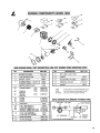
1
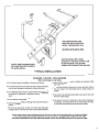
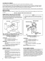
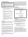
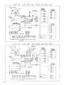
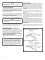
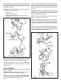
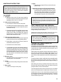
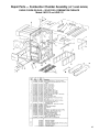
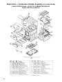
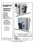
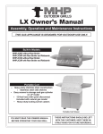
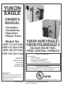
YUKON
EAGLE
OWNER’S
MANUAL
•
•
•
•
Assembly
Installation
Operation
Repair Parts
Model No.
LWO-112 (Oil Fired)
LWG-112 (Gas Fired)
LWO-168 (Oil Fired)
LWG-168 (Gas Fired)
CAUTION:
Read Rules And
Instructions
Carefully For
Safe Operation
YUKON HUSKY/EAGLE I
YUKON POLAR/EAGLE II
OIL/GAS SOLID FUEL
FIRED CENTRAL FURNACE
FOR YOUR SAFETY:
If you smell gas:
1. Open windows
2. Don’t touch electrical switches
3. Extinguish any open flame
4. Immediately call your gas supplier
FOR YOUR SAFETY:
Do not store or use gasoline or other flammable vapors and
liquids in the vicinity of this or any other appliance.
IMPORTANT:
Installation must be made in accordance with state and local ordinances which may differ from this
installation manual.
All furnaces in this owner’s manual are UL Listed in UL file #MH 11057
Alpha American Co., 10 Industrial Blvd., Palisade, MN 56469
www.yukon-eagle.com
2
INTRODUCTION
This manual provides installation, operation and maintenance instructions as well as parts ordering information for the combination oil/gas
solid fuel furnace models LWO-112 or LWG-112 and the LWO-168 or LWG-168.
IMPORTANT
Please read all instructions carefully before
attempting installation of this unit. Installation
should only be done by a qualified installer.
UNPACKING AND INSPECTION
Inspect the unit for visible damage. The furnace is shipped in three cartons.
Contents of items shipped is as follows:
FURNACE SPECIFICATIONS
MODEL LWO-112 (Oil)
Input rating
Nozzle
Burner
140,000 BTU
1.0 G.P.H. - 80 H
Wayne Model - MSR
MODEL LWG-112 (Gas)
1. Carton One: The basic furnace comes in the crate. Inside the
filter door, below the flue outlet, is the pre-assembled, circulating fan, motor, belt, drives and drip shield. The air filter lies
in a frame above the fan. Inside the furnace wood-firing door
are three wood grates, secondary air shut-off assembly, smoke
pipe draw collar, primary air draft tube and door handle weldment. Remove these items and set aside for later installation.
Input rating
2. Carton Two: This accessory package contains the secondary
air intake cover, thermostats, barometric damper, fan and limit
control, damper control unit, transformer, wiring harness, fume
sensor (gas only) and owner’s manual.
Blower Size
Blower C.F.M.
Motor Size
Firebrick Lined
Cast Iron Grates
Wood Fire Door
Air Filter
Wood Combustion Chamber Size
3. Carton Three: The oil or gas burner is in this carton pre-assembled and ready for installation.
140,000 BTU*/HR
L/P
29 (.136 dia.)
7/32” (.218 dia.)
3.5 W.C.P
10.0 W.C.P.
Wayne Model P250-AF-DI-Y
NAT
Orifice
Manifold Pressure
Burner
MODEL LWO-112 or LWG-112
10” x 10”
800 - 1800
1/3 - 1/2 - 3/4 HP
2” THICK
YES
11” x 10”
20” x 25” x 1”
24” x 16”
RULES FOR SAFE INSTALLATION AND OPERATION
1. Read these rules and the instructions carefully. Failure to follow these rules and instructions could cause a malfunction of
the furnace. This could result in death, serious bodily injury
and/or property damage.
MODEL LWO-168 (Oil)
Input rating
Nozzle
Burner
2. Check your local codes. The installation must comply with
them.
3. Use only the type of fuel approved for this furnace. Overfiring will result in failure of heat exchanger and cause dangerous operation.
4. Oil storage tanks, piping and valves should be installed and
tested in accordance with NFPA 31.
5. You must have a sufficient supply of combustion air to the
area in which the furnace is located. (page 17)
6. Factory Built Chimneys: Connect this furnace to a chimney
that complies with NFPA 211 3-1.2. Factory built chimneys
for use with wood-burning appliances shall comply with the
HT requirements of UL 103 or CAN/ULC-S629-M87. This
means you must install what is referred to as type HT all fuel
chimney.
Masonry Chimneys: Connect this furnace to a chimney that
complies with NFPA 211 3-1.2. A field constructed chimney of
solid masonry units, bricks, stones, listed masonry chimney
units, or reinforced Portland cement concrete that is lined with
suitable chimney flue liners and built in accordance with the
provisions of Chapter 4 of this standard.
7. Follow a regular service and maintenance schedule for efficient and safe operation.
8. Before servicing, allow furnace to cool. Always shut off electricity and fuel to furnace when working on it. This will prevent
electrical shocks or burns.
4
189,000 BTU
1.35 G.P.H - 80 H
Wayne Model - MSR
MODEL LWO-168 (Gas)
Input rating
189,000 BTU*/HR
L/P
“F” (.257 dia.)
“23” (.154 dia.)
3.5 W.C.P
10.0 W.C.P.
Wayne Model P250-AF-DI-Y
NAT
Orifice
Manifold Pressure
Burner
MODELS LWO-168, LWG-168
Blower Size
Blower C.F.M.
Motor Size
Firebrick
Cast Iron Grates
Wood Fire Door
Air Filter
Wood Combustion Chamber Size
11” x 10”
1200 - 2000
1/3 - 1/2 - 3/4 HP
2” THICK
YES
13-1/4” x 13-1/4”
20” x 25” x 1”
24” x 18”
NOTE
It is recommended that a 2”, noncombustible, raised pad be used for the furnace. This
will prevent moisture from getting under the
furnace and causing corrosion.
5
SECONDARY AIR SHUT OFF
MODELS LWO-112 & LWG-112 ONLY
SECONDARY AIR INTAKE COVER
1. Remove secondary air intake cover from accessory
package and align over mounting holes located
above fire door assembly on face of furnace.
1. Remove round secondary air shut off disc from plastic
bag.
2. Screw disc to the intake cover just installed.
Opening the disc when burning wood provides room air to the round
perforated tubes between the top and bottom row of firebrick, thereby causing secondary combustion of the unburned wood gases as
they leave the initial flame. This patented feature increases wood
burning efficiency up to 40% while reducing smoke and creosote.
2. Insert 12 number 10 x 3/4 hex HD drill screws (furnished with cover) through mounting holes and tighten.
When burning gas or oil for extended periods of time, this disc
should be closed.
It is not necessary to provide this disc on models LWG-168 and
LWO -168. Maximum efficiency is achieved without this disc.
CLEARANCES TO COMBUSTIBLES
Above Top of
From the
Warm Air Plenum
Front
6”
48”
From Sides
and Back
From Chimney
Connector
6 Ft. of
Plenum
6 Ft. of
Plenum
18”*
18”
6”
1”
Up to 50% less clearance between combustible walls and
chimney connector to furnace and ducts is allowed if
insulated according to NFPA Standard 90B or your local
building code. This copyrighted book is available from the
National Fire Protection Association Inc. P.O. Box 9101,
Quicy, MA 02269-9101.
Fig. 2
6
SMOKE BAFFLES
The smoke baffles are factory installed and
must be checked to see that they have not
become dislodged during shipping. Refer to
Fig. 6 for proper installation and, if necessary to reposition, proceed as follows:
1. Holding baffle in proper position, tilt
rear up to clear baffle mounting
brackets.
2. Push baffle up to top of combustion
chamber above all three brackets,
level off, slide left and lower onto
mounting brackets.
3. Check to see that all three brackets are engaged.
4. Repeat with second baffle, making sure baffles interlock as shown in Fig. 6. When properly installed, baffles will not move
more than 1/4” in any direction. Failure to have baffles properly installed will severely affect combustion efficiency.
INSTALLING THE HONEYWELL FAN/LIMIT CONTROL
1. After attaching the warm air sheet metal plenum to the
furnace, using the fan/limit control white mounting flange
as a template, place it on the top edge of the furnace
casing above the fire door so that the holes in the furnace casing and the flange are aligned with each other.
Attach the screws to secure the flange. (See Fig. 7)
19”
2. Using the flange as a template, mark the center of the
large hole and the two smaller holes, remove the bracket
and drill a 7/8” hole and two 1/8” holes in the sheet metal
plenum.
3. Replace the flange and reattach it with the mounting
screws.
4. Mount the fan/limit control ridged bracket (furnished with
the fan/limit control) with two 1/2 x 7 sheet metal screws.
5. Insert the fan/limit control into the bracket. Align so that it
is straight. Tighten setscrew to secure control.
MOUNTING THE THERMOSTATS
The thermostats must be mounted on an interior centrally located wall away from direct
sunlight and drafts and approximately 5 feet above the floor. It is not required that they be
level. Place them right next to each other.
Two Honeywell digital thermostats are furnished with all multi-level furnaces. The larger
thermostat controls your gas, oil or electric, whichever back-up fuel you have. It offers
one setting for the temperature you want the burner started in the event your wood supply
is not adequate to keep your home at its temperature setting. It also has a night setback
feature that allows you to keep a lower temperature at desired times. This thermostat
also controls the air conditioning, if applicable.
The smaller thermostat controls the wood/coal room temperature. It does not have a
night setback feature.
If you have no plans for air conditioning now or in the future, you will need a 3-wire
thermostat cable from your furnace to your thermostat. If you intend to install air conditioning either now or in the future, a 5-wire thermostat cable is required.
TYPICAL THERMOSTAT
SETTINGS
The wood thermostat (the smaller one) is
set on 74 degrees. The larger thermostat is
set at 70 degrees. The night setback on the
larger thermostat is set at 66 degrees. The
wood thermostat calls for heat first by opening the air to the wood fire. It opens and closes automatically to keep the temperature at
74 degrees. If you run low or out of wood,
the burner will come on automatically when
the temperature in the home reduces to 70
degrees, or if the thermostat were in the setback mode, the burner would not start until
it is called on at 66 degrees.
When the expensive fuel is burning, the
wood thermostat goes blank.
7
OIL BURNER INSTALLATION
NOTICE
• Model LWO-112 burner has a (140,000 BTU input)
1.00 G.P.H. 80 degree H nozzle installed at the factory.
• Model LWO-168 burner has a (189,000 BTU input)
1.35 G.P.H. 80 degree H nozzle installed at the factory.
GUN ASSEMBLY ADJUSTMENT
The gun assembly can be adjusted in the slot of the fan housing by
loosening screw holding slot cover in position. Adjust nozzle tip so
it is located 7/8” behind the front face of the burner cone.
Install burner as follows:
1. Make sure hole in side of pyrolite chamber lines up
with hole in the end of the blast tube.
TWO LINE SYSTEM
Use a two-line system when it is necessary to lift the fuel from the
tank to the burner. On outside buried tanks, install a supply line
from the tank to the burner and return line from the burner back to
the tank. The supply line is called the suction line. The suction line
should extend down to within a few inches of the bottom of the fuel
tank.
OIL FILTER
A fuel filter should be used with either an outside or inside fuel tank.
In all cases install the filter in accordance with local codes. The
filter should always be installed inside, near the furnace. An inside
tank shall be placed not less than 5 feet horizontally away from the
furnace or any internal or external fire or flame appliance being
served by the tank.
2. Remove nuts from burner mounting studs on face of
the furnace.
New oil replacement cartridges should be installed annually or as
required. Always use the new gasket that is supplied with the replacement cartridge. Tighten the top of the filter carefully and check
the gasket for proper fit.
3. Place gasket (packed on burner box) over studs and
install drip-shield. (Shipped in blower compartment.)
FILL AND VENT PIPES
4. Insert burner tube into furnace so that burner mounting flange is tight against the drip-shield and furnace
front.
5. Install mounting nuts and tighten.
CAUTION
This furnace is not approved for use with aluminum wire.
FUEL TANKS AND FUEL LINES
Fuel tanks and fuel lines must be installed in accordance with requirements of NFPA 31.
If the fuel lines are under 30 feet in length, it is satisfactory to use 3/
8” O.D. copper tube. Never use tube smaller than 3/8” O.D. If the
lines are over 30 feet in length, we recommend 1/2” O.D. tube. Use
good flare connections on the fuel lines and, whenever possible,
avoid splicing the tube. Never make a splice or joint underground.
Whenever possible, avoid overhead lines; avoid kinks and traps in
the lines. Do not fasten fuel lines directly to floor joists, sills, or
girders. Whenever possible, support fuel lines with sound-absorbing devices.
SINGLE LINE SYSTEM
Use a single line hookup only when fuel does not have to be lifted
from the tank to the burner. When the outlet on the fuel tank is
higher than the inlet on the burner, a single line system can be
used.
Fuel tanks must be equipped with a fill pipe and a vent pipe. Fill
pipes should be terminated in a convenient place for filling and
should be equipped with a watertight cap. It is recommended that
1-1/4” pipe be used for the vent. The vent should extend outdoors
and an approved vent hood should be used.
ELECTRIC WIRING
All electrical wiring must be done in accordance with the National
Electrical Code and the code legally authorized in the area where
the installation is being made. The circuit protector device must be
located in a convenient place near the furnace. No lighter than No.
14 wire should be used in the furnace power supply circuit. All furnaces covered by this manual and installed in the United States of
America operate on 115 Volts, 60 Cycle, 1-Phase Alternating Current with a 20 amp circuit protector device
WARNING
Turn off electric power at circuit protector device before
making any line voltage connections.
WIRING THE FURNACE
The furnace wiring is provided in harness form.
Mount the 4 x 4 junction box on 7/8 inch diameter opening on front
of blower compartment and secure with conduit connector and locknut for blower motor lead conduit and at least one screw.
Connect components as shown in wiring diagrams on pages 11- 12.
NOTE
24 volt wires from the transformer to DS-103 control, from
burner to DS-103, and from thermostat to DS-103 need not
be enclosed in conduit unless required by local codes.
9
GAS BURNER INSTALLATION
Model LWG-112
A 7/32” dia. orifice has been installed at the factory
(140,000 BTU input - nat. gas). To convert to LP gas, see
manufacturers instructions packed with the burner.
Model LWG-168
A “F” (.257 dia.) orifice has been installed at the factory
(189,000 BTU input - nat. gas). To convert to LP gas, see
manufacturers instructions packed with burner.
Install burner as follows:
1. Make sure hole in side of pyrolite chamber lines up
with hole in the end of the blast tube.
The gas line should be a separate supply direct from the meter to
the burner. It is recommended that new pipe be used and located
so that a minimum amount of work will be required in future servicing. The piping should be installed so as to be durable, substantial
and gas tight. It should be clear and free from cutting burrs and
defects in structure or threading. Cast iron fittings or aluminum tubing should not be used for the main gas circuit. Joint compounds
(pipe dope) should be used sparingly on male threads only and be
approved for all gases.
GAS PIPE SIZING
Check with your local gas supplier to determine total gas load for
all of your gas appliances. Size pipe accordingly.
2. Remove nuts from burner mounting studs on face of
the furnace.
3. Install drip shield (shipped in blower compartment)
over studs. Place gasket (packed in burner box) over
drip shield.
4. Assemble mounting flange over burner blast tube (flat
surface away from burner housing). Do not tighten
clamping screws.
5. Insert burner tube into furnace. Align holes in mounting flange over studs on furnace. Replace nuts removed in step 2 above an tighten.
6. Insert burner so that burner housing is tight against
mounting flange (end of blast tube should be flush
with inside of pyrolite chamber). Level burner and
tighten clamping screws.
GAS PIPING
All piping must comply with local codes. In the absence of local
codes, follow the national fuel gas code ANSIZ-233.1. A sediment
trap or drip leg must be installed in the supply line to the burner.
(See Fig. 9, page 10)
A union shall be installed in the gas line adjacent to and upstream
from the control manifold and downstream from the manual main
shut-off valve.
A manual shut-off valve shall be installed in the gas supply line
with a 1/8” N.P.T. plugged tapping for test gauge connection.
The building structure should not be weakened by the installation
of the gas piping. The piping should not be supported by other
piping, but should be firmly supported with pipe hooks, straps,
bands or hangers. Butt or lap welding pipe should not be bent.
The gas piping should be installed so as to prevent an accumulation of condensation and must be protected against freezing. A
horizontal pipe should be pitched so that it grades toward the
meter and is free from sags. The pipe should not be run through
or in an air duct or clothes chute.
After the piping and meter connections have been checked for
leaks, purge the system of air. Be sure to relight all pilots on other
appliances.
10
FUME SENSOR
The FUME SENSOR is a manual reset heat/pressure sensor
which will shut down the gas burner in the event of a chimney
down draft, plugged chimney, plugged smoke pipe or a plugged
secondary heat exchanger. In the event of a shut down, check
above and correct before resetting sensor and putting furnace
back into operation. Wire per schematic.
MOUNTING FUME SENSOR (GAS MODELS ONLY)
1. Screw fume sensor into threaded hole located in
secondary air intake cover.
2. Align sensor so that the air slot on back of sensor
cover is in the vertical position and tighten clamping
nut.
INSTALLING AIR CONDITIONING COIL
The coil should always be installed in the warm air plenum. The
metal condensate pan should be at least 2 inches above the fan
limit control probe so that the heated air flow direction is not
changed. The air flow needed for gravity operation in the event of
an electric power or furnace fan failure must not be restricted. It is
recommended that you install manual dampers along side of the
condensate pan that can be manually removed or opened for winter operation.
CAUTION
Do not use any smoke pipes less than 24 gauge between
furnace and chimney.
CONNECTING SMOKE PIPE
Set the smoke pipe end of the furnace as close to the chimney as
possible. For every foot of lateral pipe, the rise of the smoke pipe
toward the chimney must be at least one inch. Do not exceed 10
feet in length. A cleanout tee should be installed for removal of soot
and fly ash. (See Fig. 3, page 8)
Do not install the smoke pipe longer than necessary to reach the
chimney for purposes of trapping heat. The smoke outlet temperature is designed so that the heat emitted is needed to carry the byproducts of combustion out through the chimney.
The smoke pipe must not pass through any combustible material.
WARNING
No damper, heat saver or automatic vent damper device except the barometric draft regulator should be installed in or
on the smoke pipe.
The smoke pipe entrance into a masonry chimney should be at
least 2 feet above the cleanout. The smoke pipe must not extend
into the chimney beyond the inner face of the chimney liner.
PROPER CHIMNEYS
The National Fire Protection Association (NFPA) requires that all
factory built chimneys be Listed and installed in accordance with
conditions of the Listing in the manufacturers instructions. NFPA
also requires that your chimney extend at least three (3) feet above
the highest point when it passes through the roof and at least two
(2) feet higher than any portion of the building within ten (10) feet of
the chimney.
Factory built chimneys must be what NFPA refers to in
NFPA 211 1-5.217.4* as Type HT. HT is an abbreviation meaning
high temperature.
Masonry Chimneys as referred to in NFPA 211 1-5.2.17.6, a field
constructed chimney of solid masonry units, bricks, stones, listed
masonry chimney units, or reinforced concrete that is lined with
suitable chimney flue liners and built with the provisions of Chapter
4 of this standard.
As described in NFPA 54 (National Fuel Gas Code) section 7.5.5.
(c) A Listed combination gas- and solid fuel appliance equipped
with a manual reset device to shut off gas to the main burner in the
event of flue gas spillage shall be permitted to be connected to a
single chimney flue. The chimney flue shall be sized to properly
vent the appliance.
All gas-solid fuel and oil-solid fuel combination furnaces in this
manual are Underwriters Laboratories (cULus) Listed for one (1)
flue.
LESSER CLEARANCES TO COMBUSTIBLE
MATERIALS ALLOWED
This furnace is UL Listed thus requiring 18 inches from the smoke
pipe to a combustible surface. A reduction of 9 inches from a combustible ceiling and 12 inches from a combustible wall is allowed if
the space is insulated according to NFPA 90B, table 6-5.1.2.
DO NOT CONNECT THIS FURNACE TO A CHIMNEY
SERVING ANOTHER APPLIANCE
The chimney should be no less than 8 inches inside diameter or
equal.
WARNING
Check your chimney. The chimney is a very important part
of your heating system. It must be the right size, properly
constructed and in good condition. No furnace can function
properly with a bad chimney. The chimney must supply a
draft of at least .03 Water Column. If possible, use a 15 foot
or higher chimney. Add an additional foot to the chimney for
each 1000 feet of elevation above sea level.
Fig. 12
14
FURNACE LOCATED IN CONFINED SPACE
OPERATION — OIL FIRING THE UNIT
When the furnace is in a utility room, install two open grilles in a
wall or door opening to the rest of the house. One grille will supply
combustion air. Locate it near the floor. The other grille is for ventilation. Locate it close to the ceiling. Each grille must have a free
area of not less than one square inch for each 1000 BTU/hr. of the
total input rating of all the appliances in the confined space. (See
Fig. 16 below)
To start the oil burner, proceed as follows:
FOR EXAMPLE: Your furnace is rated at 150,000 BTU per hour.
The water heater is rated 30,000 BTU per hour. The total is 180,000
BTU per hour.
You need two grilles, each with 180 square inches of free opening.
Metal grilles have about 60% free (open) area, so you need two
metal grilles with 300 square inches each of louvered area. The
height should be about half the width.
1. Check for oil in storage tank. No. 2 fuel oil may be used if tank
is in the basement or if buried below ground. No. 1 fuel must
be used if the tank is outside and above ground.
2. Fuses in main switch panel must be good or circuit breakers
in on position. 20 amp circuit to be used.
3. Check to see if oil valve at main tank is open.
4. Be sure nozzle of proper size is in and tightly screwed down
and that electrodes are properly spaced. See Oil Burner instructions.
5. With combustion chamber door open, set thermostat about
10 degrees higher than room temperature to make sure thermostat contacts are made. (Remember left lever on thermostat is for burner.) If wiring is properly done and all controls
properly installed and adjusted, the burner should start. If not,
check primary relay first to make sure it is properly set, and if
burner does not start, recheck wiring and all controls thoroughly. Don’t forget to check the cad cell.
6. If burner is installed with a single oil line, the burner will have
to be purged of the entrapped air in the oil line and burner
before oil will flow to the nozzle. (See burner instruction sheet
for this operation.) If a return line is used, purging will not be
necessary, although this will speed the starting of the burner if
done. If this is done, the pump should pick up its oil in less
than a minute. If ignition does not take place during this time,
allow to set for a moment and recycle. If ignition does not take
place at this time, recheck wiring and controls. Check pump
pressure and adjust to 100 psi. With stack temperature stabilized, check draft between barometric damper and furnace.
Adjust to .03 inch water column.
STARTING BURNER AFTER IGNITION FAILURE
Before proceeding, find the cause of ignition failure — plugged nozzle, dirty electric eye, sooted electrodes, plugged oil line, etc. Do
not attempt to restart burner when excess oil has accumulated or
when combustion chamber is very hot. Press reset button on primary relay control and burner should start. Do not attempt this more
than twice. If burner fails to operate, call a service technician.
WARNING
Enough air insures proper combustion and assures that no
hazard will develop due to the lack of oxygen.
FRESH AIR DUCT CAPACITIES
Fresh air duct capacities for duct supplying fresh air
BTU Per Hour Input*
Size
1/4 in. Mesh
Screen
BTU
Wood
Louvers
BTU
Metal
Louvers
BTU
3-1/4 x 12 in.
8 in. round
8 x 12 in.
8 x 16 in.
144,000
200,000
382,000
512,000
36,000
50,000
96,000
128,000
108,000
150,000
288,000
384,000
* Based on opening covered by 1/4 inch mesh screen, wood or metal louvers.
16
NOTE
If you have a fireplace, a kitchen, bath fan or water heater
that vents to the outside, add enough duct size to your fresh
air requirements to accommodate their air needs.
WARNING
Return air MUST NOT be drawn from inside the room where
the furnace is located.
COMBUSTION AIR
Make-up outside air to the furnace for proper fuel combustion
must be provided by openings to the outside of the building. The
openings of ducts supplying such make-up air shall have unobstructed areas not less than the area of the flue pipe.
NOTE
Outside air is needed to replace the air used by the burner
and wood combustion process. Outside air is also required to
replace the air used for taking the by-products of combustion
of the gas or oil burner and wood/coal smoke out the chimney.
Outside air is also needed to replace any air expelled by
kitchen or bathroom fans as well as water heater chimneys or
fans.
Failure to provide outside air to the area in which the furnace
is located will result in a negative pressure or vacuum in the
home. Smoke from the wood fire may not be drawn up the
chimney, causing creosote buildup and sometimes causing
smoke to enter the furnace room.
WARNING
You must provide for enough fresh air to assure proper combustion. The fire in the furnace uses oxygen and must have a
continuous supply. The air in a house contains only enough
oxygen to supply the furnace for a short time. Outside air must
enter the house to replace that used by the burner.
17
GAS FIRING UNIT
GAS FIRING THE UNIT.
To start burner, proceed as follows:
1. Make sure the manual shut-off valve is closed and
control knob on gas valve is in the “off” position.
2. Set room thermostat above room temperature and
allow burner to run for 5 minutes to purge unburned
gases from the unit.
3. Set thermostat below room temperature to shut down
burner.
4. Wait 1 minute. Turn manual shut-off valve on and
turn control knob to “on”. (There is no pilot on this
burner.)
5. Set room thermostat above room temperature to start
burner. Ignition should occur approximately 30 seconds after burner motor starts up.
6. If burner does not ignite, shut off burner and wait 5
minutes, then repeat steps 1 through 5.
STARTING BURNER AFTER IGNITION FAILURE
Before proceeding, find the cause of ignition failure. Refer to manufacturer troubleshooting booklet furnished with the gas burner. After
cause has been corrected, repeat steps 1 through 5 above.
CAUTION
RESTRICTED USE DURING
ELECTRIC POWER FAILURE OR
FURNACE FAN FAILURE
Furnace may be converted to a gravity system. Directions
must be followed carefully to avoid an over-fire situation.
Remove access door to blower compartment and remove
air filter. Then replace access door. Keep ash drawer tightly
closed. Do not tamper with wood primary air control. Load
wood to half the recommended normal height, approximately
4 inches above grate.
Do not overload, as no furnace fan is available to rapidly
carry away the heat. Load small amounts of wood frequently until power is restored.
Open all air registers and remove all obstructions near them.
Keep children away from air registers or burns could result.
Primary air damper and burner will operate automatically
when electric power is restored.
IMPORTANT
Keep ash drawer empty. Primary air to the wood chamber
travels under the grate. Also, if ashes are permitted to build
up above the grates, the grates will warp and eventually
burn out.
STARTING WOOD FIRE WITH
GAS OR OIL BURNER
Place three or four 6 to 8 inch diameter logs in the firebox. Set the
temperature on the small thermostat to the desired setting. Set the
temperature on the larger thermostat above room temperature. The
flame from the burner need not touch the wood to ignite.
HAND FIRING WOOD
Set the small thermostat above room temperature. Set the larger
thermostat below room temperature. The damper to the firebox
should now be open.
Place paper and kindling in the firebox as you would in a fireplace
or campfire. Add logs to top of fire once kindling is burning. Reset
small thermostat to desired room temperature.
Never leave ash drawer open, either to start fire or to provide more
heat. The furnace is designed to provide adequate heat with the
ash drawer closed.
WARNING
Never operate furnace with ash drawer open. It could cause
the fire to burn at extreme temperatures, causing metal fatigue and firebox failure.
18
DANGER
Never burn materials other than coal or wood logs, preferably split and dried. A chimney fire or heat exchanger failure
could result. This includes large amounts of corrugated boxes, wood shavings, paper scraps, dried Christmas trees,
coke, garbage, tires or other burnable products.
CAUTION
OVERLOADING WITH WOOD
Do not overload your furnace with wood. Failure or damage
to the firebox could result. Never allow the hot coals to build
up above the lower firebricks.
BEST WOOD TO BURN
BURNING COAL ON 1/2-INCH OPENING GRATES
All solid fuel, whether it is coal, pine, oak or any grain has about
12,000 BTU’s per pound if it’s moisture content is zero. Wood that
has been cut, split and air dried for 2 years has about 8,000 usable
BTU’s per pound. Hardwood such as oak or hard maple has nearly
twice the BTU’s per cord as pine or aspen because it is nearly
twice as heavy.
(Optional)
Freshly cut wood has about 50% moisture content. Wood that has
been cut and split for 2 years has about 20%. Wood must reach at
least 435º to ignite. High moisture content wood does not allow the
gases in wood to get hot enough to provide complete combustion,
thereby creating smoke and creosote, which is usable energy, but
wasted because of incomplete combustion.
Yukon/Eagle furnaces are designed to wring the most energy possible from each log. Your furnace is designed to allow the primary
air under the grate to create the initial burning. As the wood burns,
gases, which contain 40% of the energy in the wood, escape to the
top of the flame. The patented secondary air system (the round
tubes between the firebrick) draws room air into the tubes and provides oxygen to the firebox to burn these gases. The result is you
will use up to 75% less wood than stoves, furnaces or outdoor
boilers without these features.
Type
Pound
Weight
per Cord
BTU’s
Per Cord
Air Dried
Wood
Equivalent
Value #2
Fuel Oil
Gallons
White Pine
Aspen
Spruce
Ash
Tamarack
Soft Maple
Yellow Birch
Red Oak
Hard Maple
Hickory
1800
1900
2100
2900
2500
2500
3000
3250
3000
3600
17,000,000
17,500,000
18,000,000
22,500,000
24,000,000
24,000,000
26,000,000
27,000,000
29,000,000
30,500,000
120
125
130
160
170
170
185
195
200
215
GENERAL INFORMATION
This information contains the instructions for burning various types
of coal, storage of coal, and the cleaning of the furnace.
Some coal is oil-treated at the mine and some users have indicated
that it tends to make the coal more difficult to start.
Burning coal requires some patience and a regular procedure. With
improper tending, a coal fire can go out in a short time. Once the
fire starts to go out, it is almost impossible to reverse.
After a coal fire goes out, all the coal must be removed from the
furnace before the starting process can be repeated.
Our coal burning instructions are general, as coal comes in various
sizes and types. Anthracite coal is most recommended as it burns
with little smoke when burning properly.
OPERATING INSTRUCTIONS FOR BURNING COAL
GENERAL INFORMATION
CAUTION
Burn Anthracite — Bituminous — Lignite coals only
DO NOT BURN
Petroleum — Coke — Cannel Coals
IGNITION TEMPERATURE OF COAL AND WOOD
How hot does coal have to get to ignite? Following are examples of
the ignition points of various materials:
Paper ignites @ 350ºF
Wood ignites @ 435ºF
COAL:
Western lignite ignites @
Low volatile bituminous ignites @
High volatile bituminous ignites @
Anthracite ignites @
630ºF
765ºF
870ºF
925ºF
CAUTION
REMOVE AIR CONDITIONING COIL FROM WARM AIR
PLENUM IF USING FURNACE DURING FAN FAILURE OR
ELECTRIC POWER FAILURE.
If for any reason there should be an electric power failure,
either from high limit cutoff or electrical power outage, the
damper will automatically close, preventing over-fire with no
blower, thus preventing heat exchanger damage.
19
WHAT SIZE COAL SHOULD I BURN?
The air space between the furnace grates is 1/2 inch; therefore,
coal smaller than 1/2 inch can fall through the grates into the ash
pan.
Pea size coal ranges from 9/16 to 11/16 inch.
Nut size coal ranges from 1-3/16 to 1-5/8 inches.
Stove size coal ranges from 1-5/8 to 2-7/16 inches.
Nut size is preferred by most people and is recommended for
use in this furnace.
Anthracite coal is hard and burns like the charcoal that is used in
your barbecue grill. The coals must touch each other to ignite. Therefore, the smaller the coal, the easier to ignite. Stove coal is not as
likely to touch each other because of its size.
Bituminous coal is soft and not as desirable as hard coal. It creates
dust when handled and produces large amounts of smoke and soot
when burned at a slow rate. Also, soft coal from some areas of the
country contains higher sulfur content, but a large portion of it may
be removed if the coal is cleaned.
red coals appear in the ash pan. Under-shaking restricts the amount
of air that reaches the fire and over-shaking may cause the fire to
go out.
A coal fire should never be poked or broken up as this serves to
bring ash to the surface of the coal bed where it may fuse into
lumps or clinkers which interfere with proper burning.
IMPORTANT
Never smother fire when adding fresh coal.
Anthracite Coal — To bank the fire for the night, pile the coal higher
to the back of the firebox and allow it to slope toward the fire box
door. Always leave some red or burning coals uncovered in the
front of the firebox.
Bituminous Coal — To bank the fire for the night, shake the fire and
add coal, forming the center cone. Allow enough time for the volatiles to burn off before closing the fire door.
GRATE CARE — ASH REMOVAL
HOW TO START A COAL FIRE
CAUTION
Do not use kerosene, gasoline, thinners, etc. to start a
coal fire.
To start a coal fire, place a small amount of crumpled paper and
sticks of kindling wood on the ash-covered grates.
Ignite the paper and after the wood is burning briskly, cover with a
thin layer of coal. As the first layer of coal becomes ignited, add
more coal gradually until the fire bed is built up to approximately 6
inches deep. As fresh coal is added always leave some of the glowing coal uncovered.
Draw the top red coals toward the front of the firebox and pile fresh
coals toward the back.
The grates must be protected from direct contact with the fire by a
layer of ash, one (1) or two (2) inches thick. The ash left on the
grate will help prevent overheating of the cast iron grates and coal
from falling through the grate’s opening.
It is necessary that ashes be removed from the ash pan on a daily
basis and should never be allowed to accumulate high enough to
come in contact with the grates. Such a condition could cut off necessary air circulation and could also result in a warping or burnout
of the grates.
ASH DISPOSAL
Unlike wood ashes, coal ash should not be spread on the garden.
The minerals in coal ash contain several chemicals which could be
harmful to plant life.
RECOVERING UNBURNED COAL
Screen coal ashes through a piece of 1/4 inch or 3/8 inch mesh
hardware cloth to recover any unburned coal that has fallen though
the grates
STORAGE OF COAL
Coal may be stored indoors or outdoors, with some precautions:
1. The storage area must be free of materials that are
easily burned, such as paper, wood, rags and leaves.
MAINTAINING A COAL FIRE
Bituminous coal should be built into a cone shape once the fire has
started. When refiring, break up the cone a little using a poker, especially if it has caked over to form a crust. Be careful not to mix the
coal as this increases the chance of forming clinkers.
Western lignite coal should be burned the same way you would
burn wood. (Refer to wood burning instruction.)
SHAKING THE GRATES
Shaking a fire should only be done if room is needed for fresh coal
or if the ash accumulation on the grates is excessive. Generally,
the grates need only be shaken once or twice a day.
Shake the grates using a few short strokes and stop when the first
20
2. Alternate wetting and drying of coal should be avoided. Outside storages should be protected from rain
or snow. Wet coal should not be piled on dry coal.
3. Locate the storage area in a cool, 75º F or lower,
area.
4. Nut coal weighs approximately 58 lbs. per cu. ft. A
storage bin 4-feet square by 4-feet high will hold 2
tons.
CLEANING FURNACE AND CHIMNEY FLUE PIPES
Be sure to check and clean the furnace heat exchange flue pipes
and chimney on a frequent basis. Soot and fly ash should not be
allowed to build up on any of these surfaces. Chimneys are best
cleaned professionally.
CHECKS AND ADJUSTMENTS
If you have installed your own furnace, we ask that you call for an
inspection by a Service Technician. The peace of mind and assured performance are well worth the cost involved. A technician
has the proper instruments to make the necessary check and adjustments.
DUCT WORK AND BLOWER SPEED ADJUSTMENT
FURNACE BLOWER ADJUSTMENT
A high temperature rise will result in excessive fuel usage, due to
the high stack temperature that always accompanies a high air temperature rise. It can also cause premature heat exchanger failure.
Set adjustable motor pulley so blower will give approximately 90º F
temperature rise through furnace. After pulley has been adjusted
check bolt as follows: (see Fig. 18)
The belt is drawn tight during shipment; therefore both belt tension
and sheave alignment must be rechecked by the installer when the
furnace is placed in service.
Improper belt tension and pulley misalignment are the major causes of furnace fan noise and failure of belts and bearings.
Sheave alignment is easily determined with a straight edge held
across the outer face of the fan sheave. The face of the motor sheave
should also be parallel to the straight edge at all points.
Proper belt tension is more difficult to determine accurately. Too
little tension will permit slippage causing belt wear and may cause
noise or squealing when the motor starts. Excessive tension increases motor load and may cause the oil film between shaft and
bearing to fail. This, in turn, causes the bearing to seize or burn out.
The proper belt tension is the minimum which will drive the blower
without slippage. This varies with sheave diameter, fan size, and
motor starting torque characteristics. The practical belt tension can
best be determined by actual experience, but when in doubt it is
better to have the belt too loose rather than too tight. Belt tension
can be judged by grasping the belt as shown. The belt should be
deflected approximately one inch when moderate pressure is applied.
AIR CONDITIONING
See air circulating fan performance curve charts on page 26 for the
LWO-112 model and the LWO-168 model. Service factors for factory furnished motors are 1/3 HP = 1.35, 1/2 HP = 1.25, 3/4 HP =
1.15. All motors are Class A with Class B insulation.
Supply and return duct system should be sized properly for efficient operation. Normal air temperature rise through the furnace
should be adjusted to approximately 90º F. Proper blower speed
adjustment, in conjunction with adequate duct work are necessary
to achieve this.
To perform temperature rise check, start furnace and let it run a
minimum of 10 minutes (be sure all duct work is complete and furnace is in its normal operating condition). Place #1 thermometer in
the return near the furnace. Place #2 thermometer in the supply
duct near the furnace, but not in the plenum. After 10 minutes or
more operation, take thermometer readings. Supply air temperature should be no more than 90º higher than return air temperature.
Air temperature rise can be lowered by:
1. Increasing blower speed.
2. Additional supply or return outlets.
3. Lowering firing rate.
TESTING INSTALLATIONS FOR EFFICIENCY
IMPORTANT
Draft gauge must be used. Draft in smoke pipe must be set
at .03 Water Column updraft. Failure to set properly will cause
fuel to be wasted, heating will not be satisfactory, fast buildup of creosote in heat exchanger and chimney may occur
and cause damage to your heating system.
The draft regulator will afford the user maximum fuel efficiency,
however, the finest draft regulator in the world cannot increase the
efficiency of a heating system if the system as well as the regulator
is not in proper adjustment.
Many common tests are available to establish the efficiency of the
system. One such test is outlined on page 22.
21
Basically, stack temperature and percentage of CO2 are a measure
of stack losses for any fuel. Therefore, many of the basic principles
can be and should be applied to oil-fired furnaces as well as for
those burning solid fuels.
In preparation for these tests, the following should be checked. The
Draft Regulator installed should be:
•
•
•
•
plumb and level
in the same room as the unit
on the side of a vertical, sloping or horizontal smoke pipe
located close to the furnace
Step 3. Insert the sampling tube of the CO2 tester in the hole that
you have drilled adjacent to the stack thermometer and find the
percentage of CO2 in the sample of the products of combustion.
Follow the instructions of the manufacturer of the instrument you
are using.
Step 4. Use efficiency finder chart or stack loss slide rule to determine efficiency. (See Fig. 21.) Be sure to subtract room temperature from stack thermometer reading and use this net stack temperature for determining the efficiency.
Step 5. Insert end of smoke tester into same hole as was used to
test for CO2 and perform the smoke test.
Step 5. The filter paper from the smoke test, when compared to
the standard, must be determined and be found to be satisfactory.
It should never be greater than #2, preferably #1 or zero, depending on local requirements or your own service standard. (See Fig.
21.)
Repeat steps 3, 4, and 5 as needed, adjusting the air shutter on the
burner and draft regulator until you obtain the highest possible efficiency. It is desirable to have a high CO2 reading and low stack
temperature with a minimum smoke reading.
Fig. 20
Drill two holes approximately 1/4 inch in diameter in the flue pipe
between the outlet from the furnace and the Draft Control.
Insert a stack thermometer in one of the holes and leave it there
continually during the test so that you can refer to it at any time.
(See Fig. 20.)
TEST PROCEDURE
Step 1. Set the thermostat high enough so that the unit will run for
at least 15 minutes, t
he maximum time that should be required for the test. Let the unit
operate enough for the stack temperature to stabilize.
Step 2. For your initial set of readings, set the Draft Regulator so
that there is .03 Water Column Draft in the smoke pipe between
the flue outlet and draft regulator. (See Fig. 20.)
22
MAINTENANCE INSTRUCTIONS
CAUTION
The furnace has a high efficiency “fiber-type refractory” combustion chamber. Normal servicing of this unit does not require cleaning of the combustion chamber. If for any reason
it becomes necessary to work in the area of the combustion
chamber, use EXTREME caution.
G. Grates:
1. Keep ash drawer emptied. Failure to do this will cause
grates to warp.
H. Smoke Pipe, Chimney and Furnace Heat Exchanger:
1. Do not burn green or freshly felled wood. If you do,
creosote and soot may build up in the chimney, smoke
pipe and furnace heat exchanger. This should be
checked and cleaned several times each heating season, especially if only green wood is being burned.
OIL BURNER
A. Lubrication:
1. The two oil cups on the oil burner motor should be
lubricated every three months with a few drops of good
grade light motor oil, No. 10 or 20 S.A.E.
B. At the end of the heating season:
1. Shut off electric current to burner at fuse panel.
2. If oil strainer has not been cleaned recently, it should
be removed and cleaned (consult instruction card furnished with fuel unit).
3. Oil storage tank should be kept filled to prevent water
vapor from collecting. It is suggested the valve in the
suction line be closed. Oil storage tank should be
cleaned every 2 or 3 years to remove any sediment or
water that has collected in the tank.
C. At the start of the heating season:
1. It is advisable to have a service technician inspect and
service your burner for the coming heating season.
2. Heating plant, smoke pipe and chimney should be
cleaned and checked for repairs.
3. Lubricate burner as directed above.
4. It is advisable to have the entire electrical system inspected before putting the burner into operation after
it has been standing idle for the summer months. This
should include primary relay, limit control, thermostat.
Check the electrodes for carbon and cracks in insulators, and corrosion on all terminals of the electrodes
and transformer.
D. Emergency stops:
1. Cut off all electrical current to the burner by turning off
electrical power in main fuse panel.
E. Air filter:
1. Check and clean monthly. Change filter at least twice
a year.
F. Blower motor:
1. If motor has oil caps, oil twice yearly.
NOTE
Soot will act as an insulator which will cause less heat to be
transferred into your duct system and more heat out your
chimney, thus reducing the efficiency of both the wood and
fuel being burned.
HOW TO PREVENT RUST AND CORROSION
At the end of each heating season, clean both primary and secondary heat exchanger and ash pan thoroughly. Paint the inside of the
heat exchanger with automobile crankcase oil. This will decrease
rusting caused by summer moisture.
If black paint on firing door area wears or burns off, it can be repainted with a high temperature, flat black, air-drying paint.
CAUTION
Before cleaning chimney, smoke pipe and furnace, be sure
to turn electrical power off to the furnace and any other appliance connected to chimney. Be sure wood fire is out and
inside of furnace is cool.
CLEANING THE CHIMNEY, SMOKE PIPE
AND HEAT EXCHANGER
Avoid chimney fires. On a regular schedule, check for creosote and
soot buildup in the chimney, smoke pipe and heat exchanger. They
must be kept clean. Keep a professional chimney sweep in mind if
you have access to one.
Steel brushes are the safest for cleaning metal surfaces. Salt solutions and some chemicals may damage metal surfaces. Do not
overfire your furnace. Do not burn anything that combusts in seconds. Excessive fuel temperatures may result, thereby igniting creosote.
To clean the chimney, obtain a stiff brush with an extendible handle
and insert the brush into the chimney from the top. Continue the
brushing and sweeping downward until entire length of chimney is
cleaned.
After cleaning the chimney, the debris will be at the bottom of the
chimney at the clean-out opening. Open the clean-out door and
sweep the debris out into a metal container.
The smoke pipe from the furnace to the chimney can be cleaned
with an 8-inch diameter brush. A smaller brush can also be used.
A steel brush 3 x 8 or 4 x 6-inch, with a flexible, steel handle is ideal
for cleaning the secondary heat exchanger of furnace. The primary
heat exchanger can be cleaned with any steel brush. A furnace
vacuum cleaner may be used.
23
IN CASE OF CHIMNEY FIRE
CALL THE FIRE DEPARTMENT IMMEDIATELY!
EXTINGUISH THE FIRE IN FURNACE BY SETTING THE
THERMOSTAT ALL THE WAY TO THE LEFT TO CLOSE
PRIMARY AIR DAMPER AND SHUT OFF OIL BURNER.
EMPTY FIRE CHAMBER AND ASH PAN INTO SAFE, FIREPROOF
CONTAINER.
NOTE
Do not use your furnace until a professional inspection has
been made of your furnace, smoke pipe and chimney.
als, pending final disposal. If the ashes are disposed of by burial in
soil or otherwise locally dispersed, they should be retained in the
container until all cinders have thoroughly cooled.
CREOSOTE—
FORMATION AND NEED FOR REMOVAL
When wood is burned slowly, it produces tar and other organic vapors, which combine with expelled moisture to from creosote. The
creosote vapors condense in the relatively cool chimney flue of a
slow-burning fire. As a result, creosote residue accumulates on the
flue lining. When ignited, this creosote makes an extremely hot fire.
DISPOSAL OF ASHES
The chimney connector and chimney should be inspected at least
twice monthly during the heating season to determine if a creosote
buildup has occurred.
Ashes should be placed in a metal container with a tight fitting lid.
The closed container of ashes should be placed on a noncombustible floor or on the ground, well away from all combustible materi-
If creosote has accumulated it should be removed to reduce the
risk of a chimney fire.
SERVICE HINTS - OIL
IF YOUR FURNACE IS NOT HEATING OR GIVING ENOUGH HEAT...
POSSIBLE CAUSE:
WHAT TO DO:
Thermostat is not set correctly
• Check to see that thermostat is set on “HEAT” position and the
heat anticipator is set properly. Reset thermostat above room
temperature.
Burner is not firing properly
• Contact your local serviceman.
No power to furnace
• Check fuse or circuit breaker. If fuse is blown, replace. If breaker
is tripped, reset. Check to be sure shut-off switch is “ON”.
No oil in tank
• Check oil tank gauge. If empty, have tank filled and start burner.
Valve in oil line is closed
• Open valve in oil line and start burner.
Oil filter plugged
• Replace filter cartridge.
Cycling on limit control
• Check to see limit control pointer is set against stop at 250º F.
Clean or replace air filter if dirty. Check to be sure all registers
and grilles are open and not disturbed.
SERVICE HINTS - GAS - (ADDITIONAL SERVICE HINTS ARE PROVIDED BY THE BURNER MANUFACTURER THAT IS INCLUDED WITH THIS FURNACE.)
WHAT’S WRONG:
WHY:
Lockout occurs 3-10 seconds after ignition
•
•
•
•
Flame not established
• Spark gap too small.
Arcing to ground
• Spark too large.
No spark
• Corroded connector.
Arcing other than across gap
• Cracked or dirty insulator.
Weak spark
• Broken high voltage lead.
• High voltage lead too close to metal surface.
No flame
• Valve malfunction.
Low flame current and/or nuisance lockouts
• Electrode improperly placed.
Nuisance lockouts
• Flame current falls below 2.5 µA.
• Low gas pressure.
Reverse polarity.
System improperly grounded.
Gas pressure too high, causing flame to lift off burner.
Sensor probe incorrectly positioned in flame pattern.
IF YOU DON’T SEEM TO BE GETTING ENOUGH AIR CIRCULATION...
POSSIBLE CAUSE:
Air filter is dirty
WHAT TO DO:
• Clean or replace air filter as necessary
Registers and grilles are obstructed
• Check supply or damper positions. Check registers and grilles to
make sure they are not closed or are not obstructed by carpet, draperies or furniture. Remove any obstructions.
24
SMOKE IN THE FURNACE ROOM
This condition is usually caused because the smoke is not being
drawn up through the chimney. Other causes could be a failed (firebox) heat exchanger. Check with your qualified furnace service provider.
Chimney causes:
1. Fresh air for combustion must be supplied to the furnace room by one of the methods described in this
installation manual. (See Fig. 17, page 17)
2. Cold chimney. Warm air rises and cool air falls. Outside chimneys are cold, which can cause downdrafts
until the chimney heats up. This usually happens in
the spring and fall of the year when outdoor temperatures are mild, not producing enough heat to warm
the chimney up.
3. Chimney not tall enough. It must terminate at least 2
feet above the peak of the roof.
4. If your home is in a valley or you have high trees
near your home or if you live on the east side of a hill
or mountain, a downdraft can occur when the wind
blows. One solution is to add a chimney cap with a
weather vane. This often will turn a downdraft into
an updraft. Another solution is to add height to your
chimney. Another solution is to add a power ventor
to the smoke pipe that operates when the thermostat is calling for wood heat.
5. The barometric draft control must be set at .03. If set
less, the chimney may not draw. If set higher, the
wood fire may draw too much combustion air, causing the room temperature to exceed the thermostat
setting.
OVER HEATING WHEN BURNING SOLID FUEL AS
YOUR PRIMARY SOURCE OF HEAT
If the furnace provides heat when the thermostat is satisfied, thereby over heating the home, at least one of these ideas will help.
1. The best answer is to use fewer logs at each filling.
This provides the maximum amount of heat while
conserving wood.
2. There are 3 pegs in the fan and limit control. One
peg is set at 250º F. Never change this setting. The
middle peg is set at 150º F. This is the temperature
setting that the air circulating fan starts. You may want
to set this setting at 160º F or higher. The bottom
peg is set at 120º F. Reset this peg to 130º F or higher. These new settings will not allow the fan to run as
much, thereby reducing the amount provided to the
rooms.
3. If you feel the furnace is oversized for your requirements, you can cover part of the grate with a piece
of heavy metal. This will retard the fire but also will
not burn as clean, causing some creosote buildup in
the firebox and chimney.
If you made any adjustments to the fan and limit control, you will
not have continuity of operation, which means that your air circulation blower may not operate continually when burning oil or gas.
GAS OR OIL PART OF FURNACE
TOO LARGE FOR THE HOME
If you or your furnace service provider feel the furnace BTU input is
too large or too high, either the gas or oil BTU input can be reduced
to as little as 75,000 BTU input. If you decide on this option, you will
have to adjust the air circulation blower to a lower speed to assure
continuity of operation. Slowing the blower down will allow the blower
to run continually if the thermostat is calling for heat from the gas or
oil burner.
SECONDARY AIR DISC
This disc is provided on models LWO-112 and LWG-112.
If you burn mainly solid fuel, this disc should be open to furnish air
over the fire. This patented combustion method will increase the
efficiency of wood or coal by up to 40%. If you use gas or oil as your
primary fuel, close the disc.
IMPORTANT
During normal operation, firing door and ash drawer must
be kept tightly closed. Air leakage will cause loss of efficiency resulting in higher heating costs. If door gaskets become
worn, replace with 1/2” fiberglass rope available from local
sources.
NOTE
If for any reason there should be an electric power failure,
either from high limit cut-off or electrical power outage, the
damper will automatically close, preventing over-fire with no
blower, thus preventing heat exchanger damage.
25
THIS CIRCULATING FAN PERFORMANCE CURVE CHART IS FOR DETERMINING
MOTOR HORSEPOWER NEEDS FOR THE LWO-112 AND LWG-112
THIS CIRCULATING FAN PERFORMANCE CURVE CHART IS FOR DETERMINING
MOTOR HORSEPOWER NEEDS FOR THE LWO-168 AND LWG-168
26
Repair Parts — Combustion Chamber Assembly (LEFT HAND SHOWN)
EAGLE-YUKON OIL/GAS — SOLID FUEL COMBINATION FURNACE
Models LWO-112 and LWG-112
27
Repair Parts — Combustion Chamber Assembly (LEFT HAND SHOWN)
EAGLE-YUKON OIL/GAS — SOLID FUEL COMBINATION FURNACE
Models LWO-168 and LWG-168
28
29
30
Model Number: __________________________________ Serial Number: __________________________________
Installation Date: _________________________________ Contractor: _____________________________________
Service Calls:_____________________________________________________________________________________
________________________________________________________________________________________________
________________________________________________________________________________________________
________________________________________________________________________________________________
________________________________________________________________________________________________
________________________________________________________________________________________________
________________________________________________________________________________________________
________________________________________________________________________________________________
________________________________________________________________________________________________
________________________________________________________________________________________________
Notes: ___________________________________________________________________________________________
________________________________________________________________________________________________
________________________________________________________________________________________________
________________________________________________________________________________________________
________________________________________________________________________________________________
________________________________________________________________________________________________
________________________________________________________________________________________________
________________________________________________________________________________________________
________________________________________________________________________________________________
________________________________________________________________________________________________
________________________________________________________________________________________________
________________________________________________________________________________________________
________________________________________________________________________________________________
________________________________________________________________________________________________
________________________________________________________________________________________________
________________________________________________________________________________________________
________________________________________________________________________________________________
________________________________________________________________________________________________
________________________________________________________________________________________________
31
YUKON
EAGLE
YUKON HUSKY/EAGLE I
YUKON POLAR/EAGLE II
OWNER’S
MANUAL
OIL/GAS SOLID FUEL
FIRED CENTRAL FURNACE
Model No.
HOW TO ORDER
REPAIR PARTS
LWO-112 (Oil Fired)
LWG-112 (Gas Fired)
LWO-168 (Oil Fired)
LWG-168 (Gas Fired)
CAUTION:
Read Rules And
Instructions
Carefully For
Safe Operation
IMPORTANT:
WHEN ORDERING REPAIR PARTS,
ALWAYS GIVE THE FOLLOWING INFORMATION:
• PART NUMBER
• MODEL NUMBER
• PART DESCRIPTION
• NAME OF ITEM
ALL PARTS MAY BE PURCHASED FROM A
YUKON DEALER, ONLINE AT OUR WEBSITE
OR FROM OUR FACTORY.
PHONE:
FAX:
E-MAIL:
WEBSITE:
1-800-358-0060
1-800-440-1994
[email protected]
www.yukon-eagle.com
Installation must be made in accordance
with state and local ordinances which may
differ from this installation manual.
Alpha American Co., 10 Industrial Blvd., Palisade, MN 56469
www.yukon-eagle.com
32