1
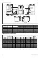
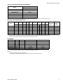
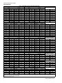
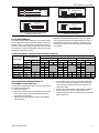
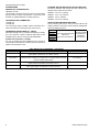
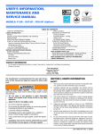
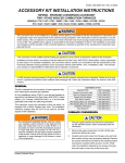
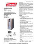
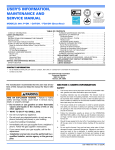
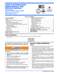
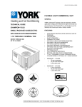
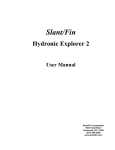
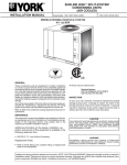
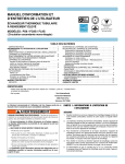
036-21584-001 Rev. B (1004)
DESCRIPTION
These Category IV, highly efficient, compact, condensing
type furnaces are designed for residential and commercial
installations in a basement, closet, alcove, recreation room
or garage where the ambient temperature is above 32°F, or
higher. They may be either side wall or thru-roof vented
using approved plastic type combustion air and vent piping.
All units are factory assembled, wired and tested to assure
dependable and economical installation and operation.
TECHNICAL GUIDE
WARRANTY
AFFINITY
MODELS: PV9
GAS-FIRED
CONDENSING / HIGH EFFICIENCY
TWO STAGE VARIABLE
UPFLOW FURNACES
Lifetime limited warranty on both heat exchangers to the
original purchaser; a 20-year limited warranty from original
installation date to subsequent purchaser.
10-year warranty on commercial applications.
5-year limited parts warranty.
FEATURES
•
UP TO 94% AFUE
NATURAL GAS
40 - 120 MBH INPUT
•
•
•
•
•
•
•
•
•
•
•
•
•
EFFICIENCY
RATING
CERTIFIED
•
•
•
This product was manufactured
in a plant whose quality system
is certified/registered as being
in conformity with ISO 9001.
Due to continuous product improvement, specifications
are subject to change without notice.
Visit us on the web at www.york.com for the most
up-to-date technical information.
Additional rating information can be found at
www.gamanet.org.
•
•
•
•
•
•
•
•
Two stage heating operation includes:
- Two stage gas valve
- Two stage inducer operation
- Variable speed ECM blower operation
Provides increased comfort level & very quiet unit operation
Adjustable delay timer allows two stage operation with
single stage thermostat
Compact, easy to install, ideal height 40" cabinet
Blower-off delay for cooling SEER improvement.
Easy to connect power/control wiring.
Built-in, high level self diagnostics with fault code display.
Low unit amp requirement for easy replacement application.
Integrated control module for reliable, economical operation.
High velocity filter and side -return filter rack provided for
easy field installation.
May be installed as either two-pipe (sealed combustion)
or single pipe vent (using indoor combustion air)
Top intake & vent connection allows installation in narrow
locations.
Electronic Hot Surface Ignition saves fuel cost with
increased dependability and reliability.
Induced combustion system with inshot main burners for
quiet, efficient operation.
No special vent termination kit required.
100% shut off main gas valve for extra safety.
24V, 40 VA control transformer and blower relay supplied
for add-on cooling.
Hi-tech tubular aluminized steel primary heat exchanger.
Secondary (condensing) heat exchanger of 29-4C highgrade stainless steel.
Timed on, adjustable off blower capability for maximum
comfort.
Solid removable bottom panel allows easy application.
Easy access from front of unit for cleaning, maintenance
or service.
Protection from intake, exhaust or condensate blockage.
Insulated blower compartment for quiet operation.
ClimaTraK comfort system allows dealer to customize
comfort settings based on regional location.
FOR DISTRIBUTION USE ONLY - NOT TO BE USED AT POINT OF RETAIL SALE
036-21584-001 Rev. B (1004)
26-1/2
26-1/2
24-5/8
A
25-3/8
1-1/2” GAS
PIPE ENTRY
1-1/2” GAS
PIPE ENTRY
7/8” JUNCTION
BOX HOLE
T-STAT WIRING
7/8” K.O.
30-7/8
CONDENSATE
DRAIN 7/8” K.O.
OPTIONAL RETURN AIR
CUT-OUT (either side)
FOR USE WITH
EXTERNAL FILTER
FRAME
7/8
7/8” JUNCTION
BOX HOLE
40
21-1/2
28-3/8
21-1/2
T-STAT WIRING
7/8” K.O.
13-7/8
11
11
CONDENSATE
DRAIN 7/8” K.O.
8
7
23-3/4
30-1/8
FRONT
7/8
LEFT SIDE
1-3/8
26-3/4
RIGHT SIDE
24-3/8
1-1/4
5/8
20
5/8
D
B
C
1-3/4
26-1/2
TOP IMAGE
SUPPLY END
BOTTOM IMAGE
RETURN END
DIMENSIONS
Cabinet Dimension
Air Intake
Models
CFM
Cabinet
Size
A (in.)
B (in.)
C (in.)
D (in.)
PV9A12N040UP11
1200
A
14-1/2
13-1/2
12-1/8
6-1/4
PV9B12N060UP11
1200
B
17-1/2
16-1/4
15-1/8
8-1/2
PV9B12N080UP11
1200
B
17-1/2
16-1/4
15-1/8
8-1/2
PV9C16N080UP11
1600
C
21
19-3/4
18-1/2
8-7/8
PV9C20N100UP11
2000
C
21
19-3/4
18-1/2
8-7/8
PV9D20N120UP11
2000
D
24-1/2
23-1/4
21-7/8
10-5/8
COMBUSTION AIR SUPPLY AND VENT PIPING
MAXIMUM ELBOWS AND VENT LENGTHS
Maximum Number of Elbows*
Models
Pipe Size
Inches (cm)
40,000
1-1/2
30
25
40,000
2
70
65
60,000
1-1/2 (3.8)
30
25
60,000
2 (5.1)
60
55
60,000
3 (7.6)
85
80
75
70
65
60
80,000
1-1/2 (3.8)
20
15
N/A
N/A
N/A
N/A
80,000
2 (5.1)
60
55
50
45
40
30
20
1
2
3
Minimum
Length
4
5
6
7
8
20
10
N/A
N/A
N/A
N/A
5
60
55
50
45
35
25
5
20
10
N/A
N/A
N/A
N/A
5
50
45
40
30
20
10
5
50
40
20
N/A
N/A
5
10
5
20
80,000
3 (7.6)
85
80
75
70
65
60
50
40
100,000
2 (5.1)
25
20
15
N/A
N/A
N/A
N/A
N/A
5
100,000
3 (7.6)
85
80
75
70
65
60
50
40
20
120,000
3 (7.6)
75
70
65
60
55
45
35
25
5
Three elbows (two in vent pipe and one in the air intake pipe) are already accounted for and need not be included in the elbow count from the Table
above.
2
Unitary Products Group
036-21584-001 Rev. B (1004)
HIGH ALTITUDE PRESSURE SWITCH APPLICATION
High Altitude Pressure Switch Kit
Models
4,500 Ft to 10,000 Ft.
PV9A12N040UP11
1PS0506
PV9B12N060UP11
1PS0501
PV9B12N080UP11
1PS0502
PV9C16N080UP11
1PS0503
PV9C20N100UP11
1PS0505
PV9D20N120UP11
1PS0503
NOTE: For high altitude conversion, an orifice change may also be required. See Form 035-14447-001 for application information.
ELECTRICAL AND PERFORMANCE DATA
Models
Input
Output Nominal
Air Temp. Max. Outlet
AFUE
Rise
Air Temp.
High/Low High/Low Airflow
Blower
Max.
Min. Wire Size
Total Unit
Size
Over-current (awg) @ 75 ft.
Protect
One Way
HP Amps
In.
Amps
Blower
MBH
MBH
CFM
%
°F
°F
PV9A12N040UP11
40/26
38/24
1200
94.0
35-65
165
1/2
7.7
11x8
9
20
14
PV9B12N060UP11
60/39
56/36
1200
93.2
40-70
170
1/2
7.7
11x8
9
20
14
PV9B12N080UP11
80/52
75/49
1200
92.5
45-75
175
1/2
7.7
11x8
9
20
14
PV9C16N080UP11
80/52
75/49
1600
92.8
45-75
175
3/4
9.6
11x10
12
20
14
PV9C20N100UP11
100/65
93/60
2000
92.8
45-75
175
1
12.8
11x11
14
20
12
PV9D20N120UP11
120/78
112/73
2000
93.2
40-70
170
1
12.8
11x11
14
20
12
Annual Fuel Utilization Efficiency (AFUE) numbers are determined in accordance with DOE Test procedures.
Wire size and over current protection must comply with the National Electrical Code (NFPA-70-latest edition) and all local codes.
The furnace shall be installed so that the electrical components are protected from water.
FILTER SIZES
Models
CFM
PV9A12N040UP11
1200
PV9B12N060UP11
1200
PV9B12N080UP11
1200
PV9C16N080UP11
Cabinet Size
Side Return Filter in. (cm)
Bottom Return Filter in. (cm)
A
16 x 25
14 x 25
B
16 x 25
16 x 25
B
16 x 25
16 x 25
1600
C
16 x 25
20 x 25
PV9C20N100UP11
2000
C
16 x 25
20 x 25
PV9D20N120UP11
2000
D
(2) 16 x 25
22 x 25
* ESP (External Static Pressure) .5" WG is at furnace outlet ahead of cooling coil.
NOTES:
1. All filters must be high velocity cleanable type.
2. Air flows above 1800 CFM require either return from two sides or one side plus bottom.
Unitary Products Group
3
036-21584-001 Rev. B (1004)
AIR FLOW DATA
High
1340
1205
1255
1150
1170
1025
1045
835
950
785
865
725
High
1310
1100
1220
1000
1090
900
880
680
810
630
730
590
High
2210
1780
2040
1620
1840
1560
1470
1370
1460
1250
1310
1090
High
1045
905
825
765
High
1330
1180
1100
1010
High
1880
1670
1530
1430
HIGH / LOW SPEED COOLING AND HEAT PUMP CFM
40,000 INPUT - 3 Ton
60,000 INPUT - 3 Ton
CFM
m³/min
CFM
m³/min
Low
High
Low
High
Low
High
995
38.0
28.2
1330
900
37.7
885
34.1
25.1
1130
800
32.0
920
35.6
26.1
1220
850
34.6
835
32.6
23.7
1040
730
29.4
855
33.2
24.2
1120
770
31.7
755
29.0
21.4
920
650
26.1
780
29.6
22.1
950
660
26.9
625
23.7
17.7
740
540
21.0
705
26.9
20.0
860
610
24.4
590
22.2
16.7
690
540
19.5
665
24.5
18.8
790
570
22.4
605
20.5
17.1
630
530
17.8
80,000 INPUT - 3 Ton
80,000 INPUT - 4 Ton
CFM
m³/min
CFM
m³/min
Low
High
Low
High
Low
High
890
37.1
25.2
1660
1110
47.0
740
31.2
21.0
1550
1050
43.9
830
34.6
23.5
1610
1070
45.6
670
28.3
19.0
1440
960
40.8
720
30.9
20.4
1470
990
41.6
610
25.5
17.3
1370
920
38.8
610
24.1
17.3
1290
850
36.5
510
19.3
14.4
1130
790
32.0
580
22.9
16.4
1230
850
34.8
500
17.8
14.2
1050
720
29.7
530
20.7
15.0
1110
760
31.4
500
16.7
14.2
950
660
26.9
100,000 INPUT - 5 Ton
120,000 INPUT - 5 Ton
CFM
m³/min
CFM
m³/min
Low
High
Low
High
Low
High
1480
62.6
41.9
2280
1510
64.6
1180
50.4
33.4
1860
1190
52.7
1350
57.8
38.2
2090
1370
59.2
1050
45.9
29.7
1630
1060
46.2
1250
52.1
35.4
1880
1250
53.2
1010
44.2
28.6
1620
1030
45.9
940
41.6
26.6
1500
960
42.5
890
38.8
25.2
1410
880
39.9
930
41.3
26.3
1490
920
42.2
790
35.4
22.4
1290
790
36.5
810
37.1
22.9
1360
840
38.5
690
30.9
19.5
1140
690
32.3
HIGH / LOW HEAT CFM
40,000 INPUT - 3 Ton
60,000 INPUT - 3 Ton
CFM
m³/min
CFM
m³/min
Low
High
Low
High
Low
High
740
29.6
21.0
1110
710
31.4
645
25.6
18.3
960
640
27.2
595
23.4
16.8
870
600
24.6
590
21.7
16.7
830
570
23.5
80,000 INPUT - 3 Ton
80,000 INPUT - 4 Ton
CFM
m³/min
CFM
m³/min
Low
High
Low
High
Low
High
880
37.7
24.9
1490
990
42.2
810
33.4
22.9
1350
900
38.2
730
31.2
20.7
1220
820
34.6
670
28.6
19.0
1120
770
31.7
100,000 INPUT - 5 Ton
120,000 INPUT - 5 Ton
CFM
m³/min
CFM
m³/min
Low
High
Low
High
Low
High
1230
53.2
34.8
2150
1420
60.9
1080
47.3
30.6
1930
1290
54.7
980
43.3
27.8
1850
1190
52.4
900
40.5
25.5
1660
1070
47.0
JUMPER SETTINGS
Low
25.5
22.7
24.1
20.7
21.8
18.4
18.7
15.3
17.3
15.3
16.1
15.0
COOL Tap
A
B
A
B
A
C
B
D
C
D
C
D
Low
31.4
29.7
30.3
27.2
28.0
26.1
24.1
22.4
24.1
20.4
21.5
18.7
COOL Tap
A
B
A
B
A
C
B
D
C
D
C
D
Low
42.8
33.7
38.8
30.0
35.4
29.2
27.2
24.9
26.1
22.4
23.8
19.5
COOL Tap
A
B
A
B
A
C
B
D
C
D
C
D
Low
20.1
18.1
17.0
16.1
HEAT Tap
A
B
C
D
ADJ Tap
B
B
A
A
C
B
C
B
A
A
C
C
JUMPER SETTINGS
ADJ Tap*
B
B
A
A
C
B
C
B
A
A
C
C
JUMPER SETTINGS
ADJ Tap*
B
B
A
A
C
B
C
B
A
A
C
C
JUMPER SETTINGS
ADJ Tap*
Any
Any
Any
Any
JUMPER SETTINGS
Low
28.0
25.5
23.2
21.8
HEAT Tap
A
B
C
D
Low
40.2
36.5
33.7
30.3
HEAT Tap
A
B
C
D
ADJ Tap*
Any
Any
Any
Any
JUMPER SETTINGS
ADJ Tap*
Any
Any
Any
Any
All CFM’s are shown at 0.5” w.c. external static pressure.These units have variable speed motors that automatically adjust to provide constant CFM from 0.0” to 0.6” w.c. static pressure. From
0.6” to 1.0” static pressure, CFM is reduced by 2% per 0.1” increase in static. Operation on duct systems with greater than 1.0” w.c. external static pressure is not recommended.
NOTE: At some settings, LOW COOL and/or LOW HEAT airflow may be lower that what is required to operate an airflow switch on certain models of electronic air cleaners. Consult the
instructions for the electronic air cleaner for further details.
The ADJ “D” tap should not be used.
4
Unitary Products Group
036-21584-001 Rev. B (1004)
BLK
BLK (HOT)
WHT
WHT (NEUTRAL)
GRN
GRN
ROOM
THERMOSTAT
NOMINAL
120 VOLT
R
W
G
Y
C
LINE WIRING CONNECTIONS
ROOM
THERMOSTAT
R
W1
W2
G
Y1
Y2
C
FURNACE
CONTROL
R
W1/W
W2
G
Y1
Y/Y2
C
CONDENSING
UNIT
FURNACE
CONTROL
R
TO AIR CONDITIONER
W1/W
CONTROLS
G
Y/Y2
C
COMMON T’STAT CONNECTION
SINGLE STAGE HEATING
THERMOSTAT CONNECTIONS
CONDENSING
UNIT
TO AIR CONDITIONER
CONTROLS
ROOM
THERMOSTAT
COMMON T’STAT CONNECTION
TWO-STAGE HEATING AND TWO-STAGE COOLING
THERMOSTAT CONNECTIONS
CONDENSING
UNIT
FURNACE
CONTROL
R
TO AIR CONDITIONER
W1/W
CONTROLS
G
Y1
Y/Y2
C
COMMON T’STAT CONNECTION
R
W
G
Y1
Y2
C
SINGLE STAGE HEATING AND TWO-STAGE COOLING
THERMOSTAT CONNECTIONS
FILTER PERFORMANCE
The airflow capacity data published in the “Blower Performance” table listed above represents blower performance
WITHOUT filters. To determine the approximate blower performance of the system, apply the filter drop value for the filter being used or select an appropriate value from the “Filter
Performance” table shown below.
NOTE: The filter pressure drop values in the “Filter Performance” table shown below are typical values for the type of
filter listed and should only be used as a guideline. Actual
pressure drop ratings for each filter type vary between filter
manufacturer.
FILTER PERFORMANCE - PRESSURE DROP INCHES W.C. AND (KPA)
Filter Type
Minimum Opening Size
Airflow Range
1 Opening
2 Openings
Sq. in.
Sq. in.
Disposable
1 Opening
In w.c.
Pa
WASHABLE FIBER*
2 Opening
In w.c.
Pa
1 Opening
In w.c.
Pa
Pleated
2 Opening
In w.c.
Pa
1 Opening
In w.c.
Pa
0 - 750
230
0.01
2.5
0.01
2.5
0.15
37
2 Opening
In w.c.
Pa
751 - 1000
330
0.04
10
0.03
7.5
0.20
50
1001 - 1250
330
0.08
20
0.07
17
0.20
50
1251 - 1500
330
0.08
20
0.07
17
0.25
62
1501 - 1750
380
658
0.14
35
0.08
20
0.13
32
0.06
15
0.30
75
0.17
42
1751 - 2000
380
658
0.17
42
0.09
22
0.15
37
0.07
17
0.30
75
0.17
42
2001 & Above
463
658
0.17
42
0.09
22
0.15
37
0.07
17
0.30
75
0.17
42
* Washable Fibers are the type supplied with furnace (if supplied.
APPLYING FILTER PRESSURE DROP TO
DETERMINE SYSTEM AIRFLOW
To determine the approximate airflow of the unit with a filter in
place, follow the steps below:
1. Select the filter type.
2. Select the number of return air openings or calculate the
return opening size in square inches to determine the
proper filter pressure drop.
3. Determine the External System Static Pressure (ESP)
without the filter.
Unitary Products Group
4.
5.
Select a filter pressure drop from the table based upon
the number of return air openings or return air opening
size and add to the ESP from Step 3 to determine the
total system static.
If total system static matches a ESP value in the airflow
table (i.e. 0.20, 0.60, etc,) the system airflow corresponds to the intersection of the ESP column and Model/
Blower Speed row.
5
036-21584-001 Rev. B (1004)
ACCESSORIES
PROPANE (LP) CONVERSION KIT 1NP0580 - All units
This accessory conversion kit may be used to convert natural
gas (N) units for propane (LP) operation. Conversions must
be made by qualified distributor or dealer personnel.
CONCENTRIC VENT TERMINATION 1CT0302 (2")
1CT0303 (3")
For use through rooftop, sidewall. Allows combustion air to
enter and exhaust to exit through single common hole.
CONDENSATE NEUTRALIZER KIT - 1NK0301
Neutralizer cartidge has a 1/2" plastic tube fittings for installation in the drain line. Calcium carbonate refill media is also
avaiable from the Source 1 Parts (p/n 026-30228-000).
Sidewall Vent Termination - 1HT0901
For use on sidewall, two-pipe installations only. Provides a
more attractive termination for locations where the terminal is
visible on the side of the home.
MODEL NO.
2TH07700124
2TH13700424
2TB17700424
2ET07700224
6
EXTERNAL BOTTOM RETURN FILTER RACK W/FILTER Provides a cleanable, high velocity type filter and filter rack.
Attaches to the bottom of the furnace.
1BR0314 - For 14-1/2” cabinets
1BR0317 - For 17-1/2" cabinets
1BR0321 - For 21" cabinets
1BR0324 - For 24-1/2" cabinets
HIGH ALTITUDE PRESSURE SWITCHES These accessory kits may be used to convert units for high
altitude operation. Conversion must be made by qualified distributor or dealer personnel.
1PS0501
1PS0502
1PS0503
1PS0504
1PS0505
1PS0506
HIGH ALTITUDE PRESSURE
SWITCH KIT
(Does Not Include Orifices)
FIELD INSTALLED ACCESSORIES - ELECTRICAL
DESCRIPTION
THERMOSTAT- One-stage heat/cool. Manual changeover, integral subbase.
System Switch: Cool-Off-Heat. Fan Switch: Auto-On.
THERMOSTAT- One-stage heat. Deluxe 24V with heat only subbase, does not
include fan switch. NOTE: For one-stage cool or one-stage heat/cool, must be
used with subbase 2TB17700424.
SUBBASE (24V) - One-stage heat/cool. Manual changeover, integral subbase.
System Switch: Cool-Off-Heat. Fan Switch: Auto-On.
THERMOSTAT- One-stage heat/cool. Programmable changeover, with subbase. System Switch: Cool-Off-Heat. Fan Switch: Auto-On.
FOR APPLICATION
INFORMATION
SEE FORM
035-20506-001
USED WITH
ALL MODELS
ALL MODELS
ALL MODELS
ALL MODELS
Unitary Products Group
036-21584-001 Rev. B (1004)
NOTES
Unitary Products Group
7
NOTES
Subject to change without notice. Printed in U.S.A.
Copyright © by York International Corp. 2004. All rights reserved.
Unitary
Products
Group
036-21584-001 Rev. B (1004)
Supersedes: 036-21584-001 Rev. a (0904)
5005
York
Drive
Norman
OK
73069