1
I
I
Ie
Getting Started Guide
I
I
I
I
HP 1650A/51A Logic Analyzers
.e
•
•I
I
.e
•
•
2£&[&2
Flin-
HEWLETT
~e..II PACKARD
'C' Copyright Hewlett-Packard Company 1987
Manual Part Number 5954-2664
Printed in U"S"A. June 1987
•I
Ie
I
I
•I
.e
•
•
•
••e
I
I
Introduction
MiMi rFP-
About
this book ...
j,iIDilfM
Welcome to the new generation of HP logic analyzers. The
lIP 1650Al51A logic analyzers have been designed to be the easiest to
use logic analyzers ever. In addition to being easy to U'*'. these lOgIC
analyzers make a sigmficant contribution to digital measurement
technology
That's why we'd like you to invest your time going through tlus
Gettmg Started manual Whether you're a novice lOgIC analyzer user or
Just new to these particular models, this book will give you a working
knowledge of the HP 1650AJ51A so that you can start using it UJ solve
your measurement problems. It covers:
• front panel organization;
• how to operate the front panel;
• learning the basic menus:
• how to set up the analyzer
• how to make basic measurements.
To make the book easier to use, we have put the names of keys
<FORMAT, SELECT etc. I m bold type. And we have Inghlighted actions (rotate the knob, press the DISPLAY) in color
If you are an expenenced HP IOgLc analyzer user but new to this family
of logic analyzers, you may feel hke going directly to the reference
manual. We'd like you to reconsider and read chapters 1 through 4
first. These chapters will only take a few minutes and you will find the
user interface of the HP 1650AJ51A very friendly and easy to learn.
Don't worry ...we didn't try to cover every feature and function of the
HP 1650AJ51A Logic analyzers in this manual. That's the job of your
HP 1650,51A Reference lIr!anual Also, if you have not read the
Setting Up the Logic Analyzer booklet, please do so now.
If you're new to logic analysis...or Just need a refresher, we think you'll
find Feeling Comfortable With Logic Analyzers valuable reading It will
help you sort out any confusion you may have about their application
and show you how to get the mast out of your new logic analyzer.
•Ie
I
I
I
I
I
I
I
I
.e
I
I
Introduction
$
Chapter 1:
What Is the HP 1650AI5IA?
Chapter 2:
Getting to Know the Front Panel
.e
I
Table of Contents
2-1 Introduction
2-1 Front Panel Organization
2-2
Cursor
2-3
Keypad
2-4
Roll
2-5
Menu
2-6
DIsplay
2·7
DISC Drive
2-7 Summary
Chapter 3:
How Do I Use the Front Panel?
3-1 Introduction
3-2 Menu FIeld Conventions
3-3 Your FIrst Step
3-4
3-5
3-6
3-7
Returning to the System Configuration Menu
Exploring the System Configuration Menu
Closing Pop-up Menus
Summary
Table of Contents (Continued)
Chapter 4:
Learning the Basic Menus
4·1
4-1
4-1
4-3
4-4
4-7
4-9
4-13
4-13
4-15
4-16
4-18
Chapter 5:
Introduction
Selector Pop-up Menu
Switching Between Analyzers
Assigning Pods
Alpha Entry Pop-up Menu
C hangmg Alpha EntriesNumeric Entry Menus
Assignment/Specification Menus
Assigning Bits to Pods
Specifying Patterns
Specifying Edges
Summary
Using the Timing Analyzer
5-1
5-2
5·2
5-3
5-5
5-5
5-6
58
5-9
5-11
5-11
5-12
5-12
5-13
5-13
5·14
5-15
516
Introduction
Problem Solving with the Timing Analyzer
What Am I Going to Measure?
How Do I Configure the Logic Analyzer?
Connecting the Probes
Activrtv Indicators
Configurmg the Timing Analyzer
Specifying a Trigger Condition
Acquiring the Data
The Timing Waveforms Menu
The X and 0
The ...
The Vertical Dotted line
Configurmg the Display
Display Resolution
Making the Measurement
Finding the Answer
Summary
•
I
e·
I
I
I
•
e.
•
•I
•
e.
I
I
I
I
Ie
Table of Contents (Continued)
ill
Chapter 6:
6-1 Introduction
6-2
6-2
6-4
6-6
6-6
6-7
Problem Solving with the State Analyzer
What Am I Going to Measure?
How Do I Configure the Logic Analyzer?
Connecting the Probes
Activity Indicators
Configurmg the State Analyzer
6-9 Specifying the J Clock
6-10 Specifying a Tngger Condition
6-12 Acqurring the Data
•I
•I
.e
I
•I
I
.e
I
I
Using the State Analyzer
6-13 The State Listing
6-14 Finding the Answer
6-16 Summary
Chapter 7:
Using the Timing/State Analyzer
7·1
7·2
7-2
7·3
74
Introduction
Problem Solving with the Timing/State Analyzer
What Am I Going to Measure?
How Do I Configure the Logic Analyzer?
Configurmg the State Analyzer
7-5 Connecting the Probes
7·5 Acqurring the Data
7-6 Finding the Problem
7·7 What Additional Measurements Must 1 Make?
7·8 How Do I Re-configure the Logic Analyzer'?
7-8 Connecting the Timing Analyzer Probes
7-9 Configurmg the Timing Analyzer
7-10 Setting the Timing Analyzer Trigger
7-11 Time Correlatmg the Data
7-12 He-acquiring t he Data
7-12 MIxed Mode Display
7-13
7-14
7-15
7-16
Interpreting the Display
Overlapping Timing Waveforms
Finding the Answer
Summary
Table of Contents (Continued)
Chapter 8:
Making Hardcopy Prints
8-1
Introduction
8-1 Hooking Up Your Printer
8-2 Setting RS-2a2C for HP Printers
8-3 Setting RS-232C for Your Non-HP Printer
8-4 Starting the Printout
8-4
8-5
8-5
8-6
Ai
Print Screen
Print All
What Happens during a Printout?
Summary
-
Chapter 9:
What's Next?
Appendix A:
Logic Analyzer Turn-on Check List
Appendix B:
Loading Demo Files from the Disc
-I
e-
-I
-I
-.•
•I
•
e.
I
•
I
I.
I
I
I
I
••
I
I
I
I
1
What Is the HP 1650A/51A?
The HP 1650Al51A logic analyzers are a new generation of general
purpose lOgIC analyzers The HP 1650A IS an 80-channel logic
analyzer while the HP 1651A is a 32-channel version of the
HP 1650A Both analyzer models are capable of 100 MHz timing and
25 MHz state analysis on all channels" The HP 1651A, while only
having 32 channels, is packed with the same feature set as its big
brother, the HP 1650A, That's why you have the same manual set
regardless of whether you have an HP 1650A or HP 1651A
The key features of the HP 1650A and HP 1651A are"
•
•
•
•
•
•
•
•
•
•
•
•
•
Transitional or glitch timing modes
Simultaneous state/state or state/timing modes
Lk-deep memory on all channels
Glitch detection on all channels
Marker measurements
Pattern, edge, and glitch triggermg
Overlapping of timing waveforms
Eight sequence levels
Eight pattern recognizers
One range recognizer
Small lightweight probing
Time and number of states tagging
Pre-store
Not all of these features will be covered in this Getting Started
manual. However, you can find the details of these and all the
features of the HP 1650AI51A in the HP 1650k51A Reference
~[anua1.
••
I
I
What Is the HP 1650A/51A?
1-1
2
I
I
I
I
•
•
••
I
I
I
I
••I
I
Getting to Know the Front Panel
Introduction
The HP 1650A/51A logic analyzers have been designed to be very
easy to use The controls are located logically by function so you can
learn how to use them quickly and easily.
This chapter breaks down the front panel into these functional areas
and gives you an overview of each area
Front Panel
Organization
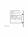
The functional areas of the front panel are: display, MENU, keypad,
CURSOR, ROLL and disc drive.
DISPLAT
~1~~~~,~6
,".",-" ..
I
f
MErJIJ
Dj2jr
DRIVE
1C~I
EE··=[-··=
l~r~i1:;;;:;II~1
..I~
I.::.JI--,--II~ 1_'I
FI~II '11'1(-"1
I . I~II ' I
=(
165C' ['29
t
I
rEt PAD
r=
~~~
1.-..1
Im'II-II' 1i:::J
' )1 • I ITI
11"'1 -
1l:~:11 ' II
I~I
~
l - f - CURSor
.,
\
ROLL
Getting to Know the Front Panel
2-1
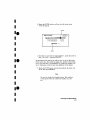
Cursor
The CURSOR lS a movable indicator on the display that allows you
to access desired fields in each menu. It changes the field where it
resides from the normal white background to the dark background
(inverse video]. The KNOB moves the cursor to the field (function I
you wish to use. You activate the field (function! by pressing the
I
e-I
SELECT key
GiD ~;~;~~
I
,-
"><1' ...... , ..,
I~
:lm"""" """,,,,,,,.
I~I
~=
I'
1-' II;;;;-II:::II~II~
1\ EE··~[-~
~
l'I.fn -
>"",
,,, ..,,,,,,,,,
21
IJ
,:~I ",,,,,,,,,,,-,- I
I" " I
' "< II II ' II ' I
-=.:===
1- 11--,-11--,-11-,-1
0
I'~~="J~
1/
I?<III
I
I~ I
cJ'"' ." (
-II-II~I
"1
~
<
::::::
1
"I,"':~II=-' '~I--'.J ITI I~I
1 II :ll~ 0
F==-'
J
\
5U 1:- lJ
,I1HCH
me a 1- "TInE ruennr
CUI'
SPEI:IFI(flTroN
( Specify symbol <;
I
[ ":CEO
I
(LOn
Jl
POD
I
,
POI)
if
I
"'ct.II.' I t~
~
~
~
~
Po I
~
I: I cc!
__ n,--~tllttttt
15
In
TTL
(locI
t r r ttt r
57
c
I I, r r t r r r r
o
I ................ I
IS
,
I
~
~
~
~
I -I)ft-
~
~
L..::Q..!..!...
.
POD
I
TTL
[I o r!
Ir t r r r r r r
15
I
I
i i
rr t tt r
I
"'
57
(
I
I (.
)=
,
MEASUREME rIT E'AMPLE
MEtlU E'AMPLE
Gelling to Know the Front Panel
2-2
I
I
I
I
I
I
e.
I
I
I
I
Keypad
The keypad allows you start and stop data acquisition as well as
enter alphanumeric data. Also in the keypad area are the DON'T
CARE and CLEAR ENTRY keys
Ie
I
I
I
I
.e
•
•I
I
.e
I
I
~"""''''''"''F''''''''",'''''
T'.. _._.I~
"n_"_"I~
"",'"
"-""",,,11,-,,,
~-
I
FIJII
-~
I
Numeric Entry
(
( s )
I
.'U
~-
II - - I I- - ! I
-II - - I I II
D
E
, -~-
STjP
,
)
( 1IS )
(~
I
c
I
';
I
6
I
I
-
~-
I-- I -e- II
-II ! I ", II
-- - -II
I -- II
I
"
I
\I
r
~
0
~
~-
[ms )
7
~-
~-
['II
(i\PE T
4
~-
'LEep
\ EIIH"
1
i
- -I -
---
,
I-,-,- I I
~ -
3
--
II - - I
':H':
Getting to Know the Front Panel
2-3
Roll
I§?~
-
'iTATE
rnenar
n.on
I
JJ
When pad of the data display is off screen, the ROLL keys define
which wa.v the KNOB will move the displayed data. You will use
these keys and the KNOB to roll displayed data up/down or left/right
to view data that is off screen
SPECIFICIITION
i
I Speufy
SYlllbols )
}=' •
I~:
Getting 10 Know the Front Panel
2-4
•I
e·
•
•
•
•
e.
I
I
•
e.
I
•
•I
Menu
The MENU area contains keys that give you access to the four major
menus of the lOgIC analyzer. You use this area to
Ie
I
I
•I
.e
I
I
I
I
.e
I
I
H50 ,-_J1
l
[-;;;:;-1 [-=-11:::11-"I
=:J '"'''' ,
I~'--'-I
• ACCE"3S disc onve functions
and set up the analyzer for
use with a printer or
controller
• Choose how the acquuec data will be
displayed
• Specify how and when each analyzer type will acquire data
for your msasurement
• Select the timing/slate format specmcancn menus where you
assign names to channels
Getting to Know the Front Panel
2-5
Display
e-I
-
I
I
e,
•
•
e.
';1151. ... (OnHgurol1on
Anal~
RnDly •• r 1
'"""~
'YPf~
I
Aulg-,~,t.
I
I
The display shows you the menus for configuring the logic analyzer
and the results of your measurements.
or :'
TIP>~
I
I-~I
Ilu, :'~rl"'
F,-, ,
I
.<11"· t I
I
I
~- TININt MAIIEFOlN'i
M'·""~ tnTr,g~ IIT;;~~~
Tim,
'" 0 I
"[[umul,l.
[]II]
,et:'D"~
11511
lUI
0 I" Tr,q ~
Ht~
n,,"~~
"
ffiC..J
FF9H
"~'ClF=========i====~===l1
"'~"II========t========l1
MENU HAMPLE
•I
I
MEASUREMENT
Getting to Know the Front Panel
2·6
E~I\MPLE
e.
I
I
I
I
Disc Drive
Ie
I
I
I
I
The logic analyzer uses the disc drive every tune you turn on the
logic analyzer to load Its operating system. The dLSC drive uses
3.5·inch flexible discs" You can also use the disc drrve to store
instrument configurations, acquired data. and mveree assemblers for
later use. Complete details on the disc drive and Its functions can be
found in the HP 1650A'51A.. Reference Afanual
-----"-,---------------------Summary
Now that you are acquainted with the front panel organization, you
will be able to decide where you want to go next. If you are just
starting to learn logic analysis, you should read this entire manual.
If you are experienced in logic analysis, you should continue to read
chapters 2 through -1 to become more familiar with the operation of
the front panel before you turn to the reference manual. These
chapters will show you how easy the HP 1650A/51A lOgIC analyzers
are to operate"
.e
I
•I
••e
I
I
Getting to Know the Front Panel
2-7
-
I
0)
r
['_) I
1.-
"
Introduction
I
I
I
I
~---
-~-
------
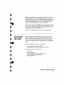
How Do I Use the Front Panel?
In this chapter you will learn how easy the HP 1650AJ51A logtc
analyzer front panel controls are to use. You will also learn the front
panel by following self-paced exercises.
This chapter starts you off in the System Configuration menu, the
same place the lOgIC analyzer starts after you turn it on. You will
learn how easy it is to get in and out of this menu. You will also
learn what the shapes of the menu fields mean.
Don't be concerned about not seeing measurement examples in this
chapter You will see them in chapters 5 through 8.
.e
•
•I
•.e
I
I
How Do I Use the Front Panel?
3-1
~
====--------------
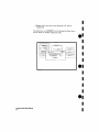
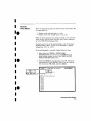
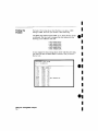
Menu Field
Conventions
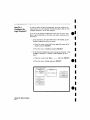
Before starting to work with the menus, you need to know the two
menu field conventions. This allows you to quickly recognize what
type of achon will occur when you select a fteld.
There are two shapes-that you should become familiar wrth'
rectangles with square corners and rectangles with rounded corners.
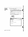
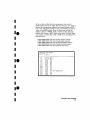
When you select a field wrth rectangular corners, it pops up and hsts
two or more items. You must select a single item.
FIelds with rounded corners will either execute the function
immediately or pop up with a list of multiple items that you must
specify.
pop-up MEflU
/
System Configuration
nnetueer
Anal yzer 1
neme !Mt'<[HH,E 1
Type
I
Timing
I
I
Name
Type
t-
Pod 1
Pad 2
--------- -
I
IMMEDIATE EXECUTE OR
MULTIPLE ITEM FIELD
a I
Off
luun
ste te
aute-scere
r-:-::-
a
!MRCHWE
1-
Pod J
-- -------
l_m_~_O_dn~_ -- n
I
I
I
_:_O_d__5______ 1
~,g"'d
Pod;
I
I
e-
•I
•I
e.
I
•I
I
e.
I
How Do I Use the Front Panel?
3·2
•
•I
·e
I
•I
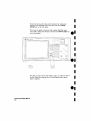
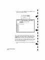
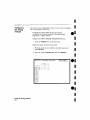
Your First Step
When you turn on the- logic analyzer and the operating system has
finished loading, you will see the System Configuration menu Notice
the cursor is in one of the fields in this menu. Operatmg the
HP 1650Al51A front panel is like learnmg to drive a car.
System tonr rqur e t tcn
Anlllyzer 1
Anlllyzer I
tlame
IMACHINE I I
Type
I
rmu nq
I nute-scet e
,
I
Type
I
une s s rqneu Pod,
,rr
I
poo
,
I
-I
I --------------Imn P:_d__~ nnI
Pod :5
Inm:O~_:_m __
1
1 ___ -
PM .5______
1
I
I
.e
•
•
•
•.e
•I
'Ib "drive" around the menu, turn the KNOB and watch the cursor
move from field to field. Most of the logic analyzer operation IS
accomplished by placing the cursor on the field you want to interact
with and pressmg the SELECT key.. Depending on the field type
nmmediate execute or pop-up) pressing SELECT will either execute
a function or open a pop-up menu.
Note
Th1S 18 the HP 1650A $ystem Format Specification menu.
If you hal'e an HP 1651A, the only difference is pod 1 will
be assigned to analyzer 1 end pod 2 n'i11 be assigned to
analyzer 2. There won't be any pods in the
UNASSIGNED area of the display.
How Do I Use the Front Panel?
3-3
Returning to
the System
Configuration
Menu
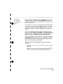
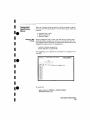
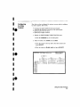
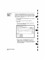
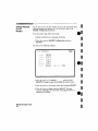
When you leave the System Configuration menu, you can return to
it at any time by following these steps:
1. Press either the FORMAT, TRACE, or DISPLAY key. You
now see a new menu, All three of these menus have a field in
the upper Left corner. 'I'his field will display either MACHlNE
1 or MACHINE 2 depending on how the logic analyzer was
configured.
2. Place the cursor on this field and press SELECT. You will see
the following pop-up menu.
3. Place the cursor on System and press SELECT, You will be
returned til the System Configuration menu.
/
suet••
MACHINE 1
MACHINE 2
/
5 stem
~gING H!RtE SPECIfICATION
MRCHINE 1 -~
MACHINE 1
ameo by
Fir:.qUl'll!oll mode] Tran:llllln~1
'"'
~
Leb e I
~
ee 3P
Find
Pettar n
@IT]
pre sent for
D I
3') ns
I
I
•1
el
1
I
1
•
e.
•I
rnen r t nd
E'lge
c=J
1
I
e.
I
How Do I Use the Front Panel?
3·4
•
•I
I.
I
•
•I
••
I
I
~:~~QI~IE!IU'~ UlIlgl
@11(~ 8~t~UI~[(UiI
::I!Jllru'Joi£l Q..~ [~iil rj,IJlljlj
II
fUTI"'ii1~~
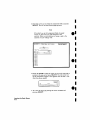
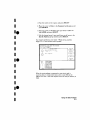
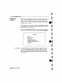
Now is a good time to explore the System Configuration menu by
driving the cursor around and pressing SELECT. Don't worry, you
can't hurt anything because no matter what field you select you will
have an easy way out,
For example, select the Harne: IIIJIACIHllIIJIE I field, and you will see
a pop-up that you can use to name analyzer number 1. In this popup menu you will see a field named Done that lets you get out of
this menu and back to the System Configuration menu where you
started,
If you select Auto-scale, the logic analyzer will display a pop-up
with the choices of Cancel and Continue" The Cancel allows you to
change your mmd before the auto-scale is executed. This is handy
because auto-scale will change your previous configuranons.
H you select Continue, the logic analyzer will display the TIMlNG
WAVEFORMS menu. However, if there IS no SIgnal activity at the
probes, the Waveforms menu will not display data and the label to
the left of the waveform area will be -off-.
To get back to the System Configuration menu after executing
Auto-seale:
1. Place the cursor on the field m the upper left corner and press
SIEILIE{:'lI'.
2 Place the cursor on §Yl~..a;~m in the pop-up and press §JElLlE{j'J['.
You will now be back in the System Configuration menu.
•I
••
I
I
How Do I Use the Front Panel?
3-5
~-----~---
Closing Pop-up
Menus
In previous exercises, you dosed the Alpha Entry pop -up by using
the Done field" But, what If there IS no Done in the other fields?
Fields that don't have choices hke Done, Cancel, or Exit will dose
automatically when you make your selection. For example, you have
used this type of pop-up to get back to the System Configuration
menu.
To see another example of a pop-up that automatically doses, follow
these steps:
Rotate the KNOB until the cursor is on the Off field in the
ANALYZER 2 field, then press SELECT You will now see the
following pop-up:
Type
I
TI~llng
( auto-scete )
I
I
l-
un
P_O_d_:_
Pod"
2 Place the cursor on State and press SELECT
The pop-up menu will automatically close, analyzer 2
the type will be State,
How Do I Use the Front Panel?
3-6
I
•
e.
\
Amllyzer 1
II'IACHINE 1
e·
I
I
Off
Timino
State
N~m~
•I
ts
now on and
•I
•I
e.
I
I
•I
Ie
•
L
Summal'lf
In this chapter you learned what menu the logic analyzer displays
once you have turned It on and where you will usually start
configuring the logic analyzer once you are ready to make
measurements
The next chapter will teach you the most common types of pop-up
menus, which will help you progress towards making measurements
as explained m chapters 5 through 7_
•I
•.e
•I
I
I
.e
I
•
How Do I Use the Front Panel?
3·7
I
I
u===-Learning the Basic Menus
~i
elntroduction
I
•I
In this chapter you will learn the most common pop-up menu types
by doing some basic exercises. The pop-up menu types you will learn
I
•I
•.e
_
in this chapter are,
•
•
•
•
Selector
Alpha Entry
Numenc Entry
Assignment/Specification
=
Selector
Pop-up Menu
In the selector type of pop-up menu you do what the name imphes,
make a selection from two or more options. The best way to
introduce you to a selector type of menu is to have you work with
one right away.
Switching
Between
Analyzers
You will use a selector type of pop-up menu to switch between
analyzers or get back to the System Configuration menu. You can
switch analyzers m the FORMAT, TRACE and DISPLAY menus,
WIthout having to go back to the System Configuration menu. This
is done easily by following the-se ste-ps'
1 Press the TRACE key. You will now be in either the TIMING
TRACE or STATE TRACE SPECIFICATION menu depending
on what you did last in the System Configuration menu.
I
.e
I
I
Learning the Basic Menus
4·1
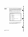
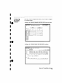
2. Place the cursor in the field in the upper left corner of the
menu and press SELECT. A pop-up menu will appear
displaying System and the current analyzer names tdefault
names are MACHINE 1 and MACHINE 21. The cursor will be
on the current analyzer.
Sustem
MACHINE 1
MACHINE 2
I
I
eI
I
I
/
/
"i stem
"RCHINE
MRCHINE
-
~TE
nRCE SPECIFICRTION
I..
~
armeo
seuuence t.eve 1 s
tnure s t nrruq enus t et e
Trigger 011 enustat e '
1 tImes
I
Pun
'"
I
sr encne s
I
011.'
I
[oun t
I
Off
I
Pr·e, tore
I
Off
I
•
e.
ITI
3. Move the cursor to the other machine I analyzer I and press
SELECT. The pop-up will close and you will see the corresponding
menu of the other analyzer on the display
I
I
I
•
e.
I
Learning the Basic Menus
4-2
•
•
•.e
•
•
•I
System (onfi!JurotlOn
anetuzer- I
neme
IMIKHINE 1
Type
I
'r rrmnq
AnBlyzer 2
Name
IMI'lCHWE
rupe
I
Siote
I auto-scete I
Pod
~
3, Place the cursor on AII1l8l1yuoJr 2 and press §lEILEGTI'. The pop-up
closes and your desired pod is now assigned to analyzer 2.
.e
I
I
learning the Basic Menus
4·3
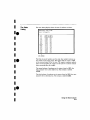
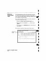
Get back to the System Configuration menu (refer to
"Returning to the System Configuration Menu" in chapter 3 if
you need a remmdert
2 Rotate the KNOB until the cursor is over MACHINE 1 and
press SELECT
You will now see a pop-up window m the System Configuration
menu as shown in the example
SY5tem Conf
mvre t rcn
aneruz er-
,
Harne IrlfiCH HIE
ryp e
I
'rmunq
Auto-sen
1-
"od
,
----
z
Ani'll y"er
,1
1
rteme
IMA[HH~E
Type
I
,
I
I
510 t e
,
Alphl'l Entry
Don~
IHBC[IEFGHI Jf L11NOPIJPSTUIIH.','
I
01 ~3..:1561El9
'I
[!lRCHINE
,
EJEJ
,
une s sr oneo
',':1
'"
,
- -- ,
POll"
- 1
Pod :;
----__ ------- ---I
Pbd
,
----------------1
I
I
e.
I
I
•I
e•
Learning the Basic Menus
4·4
•I
I
•
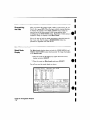
3. Rotate the KHOB and you will see how the cursor moves
within the pop-up.
••
Al ph" Entry
I
•
•
•
••
•
•
•
•
••
•
•
/
l Done
IABC DEFGH IJI,LMNOPQP.SilJVNX vzl
(1123.:..1567BQ
/1
[MACHINE I
BEl
]
MARKER
4, Now that you are ready to name analyzer 1, move the cursor so
that it is on the L and press §IEJLJEICT.
In the bottom of the pop-up. you will see an L in the far left corner
of the bottom box: Also notice the under-score marker in the bottom
box is now under the A of MACHINE. The under-score marker tells
you
In
what space m the box your next selection WIll be placed.
5. Rotate the lRJIlmB again until you have placed the cursor over
the E, then press §EJLECT,
Note
lou can also make direct keypad entries. lour selection
will be placed where the under-score marker 18 in the
box.
Learning the Basic Menus
4-5
I
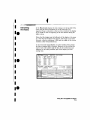
6 Repeat step 5 three more times selecting A, R, and M
respectively.
You should now see LEARMNE 1 in the bottom box. Since this is
not the name you wanted, change the name.
sus tam runr muret run
anetuzer-
anetuzer- 1
nene
Illfr(HHlE
rqpe
1
( Auto
r-eo
1-
Timing
sea
,
,
une-sruneo
1
1
TIJpe
on
I
I
,
Alphn Entry
none
IH51:[IEFGHIn LI1'IOPClPS TUVH c"
,
I (I
I 13.:156/09_
I
[lEAl!tt.!'lE 1
,
r:J 1:'1
,
- --,
Pod,
r-oo
1
,
-
POlj
-- Pod
,
---
•
e·
•
•
•
•
e.
•
•
•I
e.
learnIng the Basic Menus
4·6
•I
•
•·e
•
•
•
•.e
•I
•I
Changing Alpha
Entries
To make changes or corrections
III
the Alpha Entry field. place the
under-score marker under the character you want to change
To move the under-score marker to the left, place the cursor over the
left arrow and press SELECT once tor each backspace
(~)
Alpha Entry
JA BCDEFGH IJf:LMNOPORS TUVHX vzl
n 123~55789
BAI;kSPACES
/1
UI~OER-SCORE
MARI\ER
MOVES UNDER·SCORE
MARhER TO THE RIGHT
To move the under-score marker to the right. you either place the
cursor on a desired character and press SELECT, 01' place It on the
right arrow and press SELECT.
'lim can also use the ROLL keys and the KNOB to move the underscore marker 1'0 use this alternate method',
L Press the left/right !WILlL key.
2 Rotate the lli'],J'"OlB: to place the under-score marker under the
desired character
3 Press the left/right ROILL key again to turn off the ROLL
function.
.e
•I
Learning the Basic Menus
4-7
If you want to erase the entire entry and place the under-score
marker at the beginnmg of the name box, press the CLEAR
ENTRY key on the front panel.
If you want to replace a character with a space. place the underscore marker under that character and press the DON'T CARE key
on the front panel.
ICE ""',n
P-(H·'P
,,,,K''''L'"![II
I
I
I~~
li~~II-il'"'II' r~"·r.;l
I-"",-II-,--II-,--Il-,-I
I~;II,'II" II '
17,
I~'II~II-;-: ~
rMiI11 ' II ;-,1" I I
I
/
I
.
CC
lt~r,
E
.J~
~
I
[IIJII T
"RE
1-
j
'
'~
~-d
~\[~:'III_- :~III-I' 1I'f'I
1. .1
--
"''''
\.:~
EIITF
T
Now that you have entered and edited a name, you will know how to
use the Alpha Entry pop-up menu 10 other logic analyzer menus
where It appears.
learning the Basic Menus
4·8
e•
•
•
e•
•
•
•
e.
•
•
•
I
•I.
I
•
•
•
••
•
•
•I
••
Numeric
Entry Menus
There are many pop-up menus in which you enter numerrc data, The
two major types are:
• Numeric entry with fixed unite (LE'. volts)
• Numeric entry with variable units (i.e. rna. /lS, etc.t
There are several numeric entry menus in which ,VOU only enter the
value, and the units are fixed. One such type of numeric entry popup is the POD Threshold pop-up menu.
Besides being able to set the pod thresholds to either of the preset
thresholds (TIL or EeL). you can set the thresholds to a specific
voltage from -9.9 V to +9.9 V.
To set pod thresholds to a specific voltage, follow these steps'
L Select erther the TIMING or STATE FORMAT
SPECIFICATION menu hy pressing the FORMAT key It
doesn't matter whether you are in the TIMING or STATE
FORMAT SPECIFICATION menu.
2 Rotate the KNOB to place the cursor in the TTL field of any
pod displayed and press SEL~CT You will now see a pop-up
with the choices. TTL. EeL. and User defined.
I
TTL
Eel
User
def~ned
- I
IMACHINE 1
1- TIMING
I
rOj;!MAT SPECIrICAT [ON
en,
1IL
_ User def mea
"'
~ Pol
~
~
~
1'5
67
( Specify symbOI'i )
6
c'
G I ~"~~"~I~~+·++·I
~
~
~
~
~
~
--.:gg.:.
3lli
I
•
Learning the BaSIC Menus
4·9
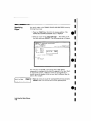
3. Place the cursor on User Defined and press SELECT Another
pop-up menu will appear as shown.
Pod Threshold ( Exit )
• 0.0
V
11"IHCHIIIE 'I
,
rmr\
.,
Poll Thresholll <1Ell)
rn,
en,
+o,ov
f""'~"
1,
I
User cer .rnee
He I'll' l t ~
~Pol
------------ -
15
67
I ++ •••• ~ . . . ++ ...... I
~G
-01 (-
~
~
~
~
~
~
~
~
::::Qtt::
You can enter your desired threshold with either of two methods
when the pod threshold pop-up is open" The first method is to rotate
the KNOB until your desired threshold is displayed Rotating the
KNOB increments or decrements the value m small Increments.
The second method is to use the keypad, which allows you to change
large values quickly. WIth the keypad follow these simple steps to
enter -5,,0 V for the pod threshold:
4, Enter 5,,0 from the keypad You will see the 0,,0 V replaced with
5,0
Learning the Basic Menus
4·10
•I
e·
•
•
•
•
e.
•
•
•
•
e.
•I
•I
•••
5 Press the CHS rchange eigru key on the front panel. 14m will
now see -5.0 in the pop-up.
Also notice the cursor IE; in the upper right corner of the pop-up over
the operative Exit When you press SELECT, the pop-up will close
and your new threshold WIll be placed III the Pod field.
Qii]
HEIILEIT
F_,"",,,
•I
I
••
•
•
•
•••
I
I
Another type of numeric entry you will use requires you to specify
the units as well as the numeric value The following steps show you
how
1 Select the TIMING TRACE SPECIFICATION menu by pressing
the TRACE key.
Note
If the STATE TRACE SPECIFICATION menu comes up,
refer to "SwItching Between Anal.'vzers" in tiue chapter.
Learning the Basic Menus
4-11
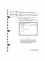
2. Rotate the KNOB to place the cursor in the 30 ns box within
the present for> 30 ns line and press SELECT You will now
see the following pop-up:
IMHCHUIE I
1- TIMING
rrece model
smut e
ar-med
by
PU~
r~IlCE O;PEUrrCATION
I
fH:qUI51110~ mOdeITran~ltlQn~11
I
t.ebe I
ae s e
FInd
Numer it En trg
Pattern ~
31) 00 I
I uc I
3 Enter a new value to replace 30.00 With the keypad. When you
have entered your desired value, you can change the units type
by rotating the KNOB.
Once you have selected the new value and the units, close the pop-up
by pressing SELECT, The new value and the units will now be
displayed in the present for
Learning the Basic Menus
4·12
>
field.
-I
e-
e.
•
e.
•
•
I
I
I.
I
I
I
I
••
•I
I
•••
L~-======~-------------1[_
'
Assignment!
Specification
Menus
There are a number of pop-up menus in which you assign or specify
what you want the logic analyzer to do The basic menus of this type
consist of
• Assigning bits to pods
• Specifying patterns
• Specifying edges
Assigning Bits
to Pods
The bit assignment fields m both state and timing analyzers work
Identically. Before startmg this exercise you need to know how the
logic analyzer knows which bits are assigned and which ones are not
assigned. The convention for bit assignment is:
" (asterisk) indicates assigned bits
· rperrodl indicates un-assigned bits,
In the following menu example, bits 0 through 7 are assigned to the
label BIT.
Ir1i1CHIIIEI
1- rIMINli
ForMAT 'iPECIFUnrION
(Specify Symllol!'> )
POD I
TTL
HC 11" I t ~
Lebel Pol
[iJ
5IT
['=5==~~~
+H+"HI...-
I
BIT ASSIGNMENT FIELD
-011-011-
-un-011-
-01
v-
-011-011-01 (-
-urt-011-
-011-011-
-0t'1-
'Ib assign bits:
l. Select either tbe TIMING or STATE FORMAT
SPECIFICATION menu.
I
•
learning Ihe Basic Menus
4-13
2. Place the cursor on one of the bit assignment fields and press
SELECT, You will see the following pop-up menu.
•I
Note
If you don't see any bit assignment fields, it merely
means J'OU don't have any pods assigned to this
analyzer. Either switch analyzers or assign a pod to the
analyzer you are working \i."ith
Im;[HINE 1
1_
TIMINI; FORI1IIT SPECIFICATION
( Speufy Symbol'.> )
POO 1
TTL
3. Rotate the KNOB to place the cursor on one of the asterisks or
periods in the pop-up and press SELECT. You will notice how
the bit assignment toggles to the opposite state of what it was
when the pop-up opened.
( Done)
15
I,~ ~
B7
+ ... +-
>l<
""
'" ... '"
(I
++ ++ + :
I
4. You dose the pop-up by placing the cursor on Done and
pressing SELECf.
Learning the Basic Menus
4·14
e·
•
•I
•
e.
•
•
•
•
e.
I
I
I
•·e
•
•
•I
.e
•
•I
••e
Specifying
Patterns
The Specify Patterns fields appear In several menus in both the
timing and state analyzers. Patterns can be specified in one of
several number bases; however, for now we'll use hexidecimal ,HEX)
since it is the default base.
Before startmg this exercise you need to know how the logic
analyzer knows which patterns to ignore (doesn't care about),
Whenever you see an "X" in this type of menu, it indicates a "don't
care,"
'Io specify patterns:
1 Select the TIMING TRACE SPECIFICATION menu.
2. Place the cursor on the Find Pattern
field and
press SELECT, You WIll see the following pop-up menu
1-
!11t'tCHII1EI
TIMINli TIIACE <;PECIfUIlTION
TraCE mlld~1
Sll'gle
I
«meo h~
Pun
I
t.ebe t
~
B~;e
F r nd
~
p et te r n ~
ac qur sr tr nn mOd8IT'~II~1110Ml
5peuf!l Pill ter-n
KUX
-0 hS
rn-n
f r no
EOge
[===:J
3 Type in 2, 3, 4, and press the DON'T CARE key" You will see
234X in the pop-up. This will be the pattern in hexadecimal
that you want the logic analyzer to recognize.
4. Close the pop-up by pressing SELECT.
I
•
Learning the Basic Menus
4·15
q·Billl!!lBI]
OJ'
Specifying
Edges
ibu specify edges m the TIMING TRACE SPECIFICATION menu by
following these steps:
L Press the TRACE key" Switch to the hmmg analyzer if the
STATE TRACE SPECIFICATION menu IS displayed
2. Place the cursor on the Then find Edge . . field under one of
the labels and press SELECT. The following pop-up wtl! appeal'.
li'It=lCHmE I
1- lInIN6
rr eco mod~1
Slnglf.!
Hrm~d by
ruen
I
sun
Tl'ACE SPEClHCAfION
I
I
HCQI.II.;lllon model Trell-Jllonlll1
lind
Edge
c==J
You WIll notice 16 periods in the pop-up menu Each period
represents an unassigned bit for each bit assigned to the label.. Don't
be alarmed if you have a different number of unassigned bits; it
merely means the number of bits in your label is different than the
label in this example.
Specify Edge:
1 . ••
••..
,...
Learning the Basic Menus
4·16
e•
-
3. Place the cursor on one of the unassigned bit periods and press
SELECT once. You will now see an arrow pointing down.
•
•
•
e.
I
I
I
I
I.
I
I
•
•
••
•
•
•
•••
•I
~
.. . .... ... .
Spec1fy Edge:
Lt-
"
~
... . ... .
Specify Edge:
L.1- t ...
4 Move the cursor to another unassigned bit period and press
SELECT twice. You will see an arrow pointing up.
5 Move the cursor to yet another unassigned bit period and press
SELECT three times. You will see an arrow pointing both up
and down
You have just selected a positve-going t l I, negative-going (I), and
either edge !I I for your edge parameter.
6. PLace the cursor on Done and press SELECf. The pop-up will
close and you will see the following display.
II1HCHH.II: I
1- TIM!N!>
rr ec e model
Sing I ~
tl,nled
b~
PUll
Leu .. l
IDL:J
8~5~
~
H'ACE SPECIFICATION
I
HCqUl~ltlD"
I
mOIJIO[T1BrI
1l.jon~11
Fl~~ttern I ~=-.j" I
Theil
r i nn
Ed9e
c::!L:J
Note
When you dose the pop-up after specifying edges, J.'OU
will see dollar signs 1$ $. I in the Then find Edge
field. These indscete edges hmce been specified; howe\Ter,
the logic enelvser can't display them correctly unless
you have selected Binary for the base.
Learning the Basic Menus
4·17
4&
Hi
Summary
i!Ji)
In this chapter you have learned some of the most common pop-up
menu types. You will use these pop-up menus as you set up the logic
analyzer in the measurement example exercises in chapters 5
through 7.
If you are already familiar with logic analysis and feel you are
comfortable enough with the HP 1650AJ51A user interface. you may
be ready for the HP 1650A'51A Reference ll.fanual.
If you are not familiar with logic analyzers or logic analysis, you
should continue with this manual,
Learning the Basic Menus
4-18
-
e•
•
•
•
e.
I
•
•
•
e.
-
5
Introduction
Using the Timing Analyzer
In this chapter you will learn how to use the timing analyzer by
setting up the logic analyzer to make a simple measurement. We
give you the measurement results as actually measured by the logic
analyzer, since you may not have the same circuit available.
The exercise in this chapter is organized in a task format. The tasks
are ordered in the same way you will most likely use them once you
become an experienced user. The steps in this format are both
numbered and lettered. The numbered steps state the step objective.
The lettered steps explain how to accomplish each step objective.
There is also an example of each menu after it has been properly
set up.
How you use the steps depends on how much you remember from
chapters 1 through 4. If you can set up each menu by just looking at
the menu picture, go ahead and do so. If you need a reminder of
what steps you need to perform, follow the numbered steps. If you
still need more information about "how," use the lettered steps.
When you have finished configuring the logic analyzer for this
exercise, you can load a file from the operating system disc. This file
configures the logic analyzer the same way it is configured for this
exercise. It also loads the same data acquired for this exercise so you
can see what it looks like on screen.
In order to learn how to configure the logic analyzer, we recommend
that you follow the exercise to "Acquiring the Data" before loading
the file from the disc.
You can also compare your configuration with the one on the disc by
printing it (if you have a printer) or making notes before you load
the file.
Using the Timing Analyzer
5·1
Problem Solving
with the
Timing Analyzer
In this exercise, assume you are designing a dynamic RAM memory
(DRAM) controller and you must verify the timing of the row address
strobe (RAS) and the column address strobe (CAS). You are using a
4116 dynamic RAM and the data book specifies that the minimum
time from when LRAS is asserted (goes low) to when LeAS is no
longer asserted (goes high) is 250 ns. You could use an oscilloscope
but you have an HP 1650N51A on your bench. Since the timing
analyzer will do just fine when you don't need voltage parametrics,
you decide to go ahead and use the logic analyzer.
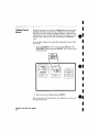
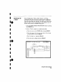
What Am I Going
to Measure?
After configuring the logic analyzer and hooking it up to your
circuit under test, you will be measuring the time (x) from when the
RAS goes low to when the CAS goes high, as shown below.
I~
(X)
,
........_--To',q...-----
RAS - - - . ,
CAS - - - - ,
Using the Timing Analyzer
5-2
15&V8LOO
I
I
••
•
•
•
•
••
•
•
•
How Do I
Configure the
Logic Analyzer?
In order to make this timing measurement, you must configure the
logic analyzer as a timing analyzer. By following these steps you will
configure Analyzer 1 as the timing analyzer.
If you are in the System Configuration menu you are in the right
place to get started and you can start with step 2; otherwise, start
with step 1
L Using the field in the upper left corner of the display, get the
System Configuration menu on screen.
a. Place the cursor on the field in the upper left corner of the
display and press SELECT.
b. Place the cursor on System and press SELECT.
2. In the System Configuration menu, change Analyzer 1 type to
TIming. If analyzer 1 is already a timing analyzer. go on
to step 3.
a. Place the cursor on the Type:
SELECT.
field and press
b. Place the cursor on Timing and press SELECT
Sygleffl runt.ruur e t.icn
Anlllyzer 1
neme
IOPHM TEST
r~pe
I
Tlmln~
An!!1 seer :'.
I
Type
I
011
( nute-scet e )
Pod
I
•••
•
•
Using the Timing Analyzer
5·3
3. Name Analyzer 1 "DRAM TEST" (optional!
a, Place the cursor on the Name:
and press SELECT.
~_ _
field of Analyzer 1
b. With the Alpha Entry pop-up. change the name to "DRAM
TEST" (see "Alpha Entry Pop-up Menu" in chapter 4 if you
need a reminder).
4. Assign pod 1 to the timmg analyzer.
a. Place the cursor on the Pod 1 field and press SELECT.
b. In the Pod 1 pop-up, place the cursor on Analyzer 1 and
press SELECT.
•I
e·
•I
I
I
e.
•
•
•
•
e.
Using the Timing Analyzer
5-4
I
I
I
I
Ie
I
I
I
I
.e
•
•
•
=====:r-----------------
=:c:,
Connecting
the Probes
At this point, if you had a target system with a 4116 DRAM
memory Ie, you would connect the logic analyzer to your system.
Since you have assigned labels and Pod 1 bits 0 and 1, you hook the
probes to your system accordingly.
Since you WIll be assigning Pod 1 brt 0 to the RAS label, you hook
Pod 1 bit 0 to the 'memory Ie pm connected to the RAS signal. You
hook Pod 1 bit 1 to the Ie pin connected to the CAS signaL
Aclivily
Indicators
When the logic analyzer LS connected and your target system is
running, you will see! at the right-most end (least significant bits)
of the Pod 1 field In the System Configuration menu. ThIS indicates
the RAS and CAS signals are transitioning,
Systl"m Confi!luratlon
Anlllljzer 1
neme
I[lPHH TEST
Type
I
Tlnlllig
(Auto-5c~le
rqpe
lOfT
)
Pod :
con__~
1
t
IlCTIVITV INDICATORS
•.e
•
•
Using the Timing Analyzer
5-5
I
ffiiJl,!;"tg'r ""
'I~ __-'
Configuring
the Timing
Analyzer
Now that you have configured the system, you are ready to configure
the timing analyzer, IOU will be"
• Creating two names (labels I for the input signals
• Assigning the channels connected to the input signals
• Specifying a trigger condition
L Display the TIMING FORMAT SPECIFICATION menu.
a Press the FORMAT key on the front panel.
2. Name two labels, one RAS and one CAS.
a Place the cursor on the top field in the label column and
press SELECT
b Place the cursor on Modify label and press SELECT
lli~- TIMING fORMAT 'iPECIF[[flrrON
POD I
TTL
t.eue t Pol
p"
(H',
-0 r (-
-ort-0 r t-0 r t-
-011-
-olr-0 I t-
-0 r (-Oft-
-011-
Using the Timing Analyzer
5·6
-or
t-
-0 I
j-
':11
B
I
11
HCl.l~lty
15
67
:1
( suec rru Symbols
I
•
e·
•
•
•
•
e.
•
•
•
•
e.
•
•
•
•
•••
•
•
•
••
c. With the Alpha Entry pop-up. change the name of the label
to RAS (see "Alpha Entry Pop-up Menu" in chapter 4 If you
need a reminder)
d. Name the second label CAS by repeating steps a through c.
3. Assign the channels connected to the input signals (Pod 1 bits
o and 11 to the labels RAS and CAS respectively,
a. Place the cursor on the bit assignment field below Pod 1 and
to the tight of RAS and press SELECT
b Any combination of bits may be assigned to this pod:
however, you will want only bit 0 assigned to the RAS label
The easiest way to assign bits is to press the CLEAR
ENTRY key to un-assign any assigned bits before you start.
c. Place the cursor on the period under the 0 in the bit
assignment pop-up and press SELECT This will place an
asterisk in the pop-up for bit 0 indicating Pod 1 bit 0 IS now
assigned to the RAS label.. Place cursor on Done and press
SELECT to close the pop-up.
d. ASSign Pod 1 bit 1 to the CAS label by moving the cursor to
bit 1 and pressing SELECT
•
•
•
•••
•
•
Using the Tlmmg Analyzer
5-7
t'
'rE5?tt
Specifying a
Trigger
Condition
To capture the data and then place the data of interest in the center
of the display of the TIMING WAVEFORMS menu, you need to ten
the logic analyzer when to trigger. Since the first event of interest IS
when the LRAS IS asserted cnegative-gmng edge of RAS), you need
to tell the logic analyzer to tngger on a negative-going edge of the
RAS signal
Select the TIMING TRACE menu hy pressing the TRACE key.
2_ Set the trigger so that the logic analyzer triggers on the
negative-going edge of the RAS.
8_
Place the cursor on the Then find Edge field under the
lahel RAS, then press SELECT.
b. Place the cursor on the. (period!
III the pop-up and press
SELECT once Pressing SELECT once in this pop-up
changes a period to I which indicates a negative-gomg edge
c,
Place the cursor on Done and press SELECT_ The pop-up
doses and a $ will be located in this field. The $ indicates
an edge has been specified even though it can't be shown In
the HEX hase.
![IRArl TEST
1- TIMING
TI'RCE 5PECIFURTIOfl
Lab e I
c::PB:OCI8:0
ae 5 e
~c::B:L::J
FI
no
p ettar n
men
f1M
Edge
~c:::z::::::J
~c=J
•
•
e·
•
•
•
•
e.
•
•
•
•
e.
I
Using the Timing Analyzer
5-8
•
I
I
·e
•
•
•
•.e
•
•
•
•.e
•
•
I ~"I
'hll@,
_"t '"
Acquiring
the Data
I '
~,,-
Now that you have configured and connected the logic analyzer, you
acquire the data for your measurement by pressing the RUN key,
The lOgIC analyzer will look for a negative edge on the RAS signal
and trigger if It Bees one When it triggers, the display switches to
the TIMING WAVEFORMS menu
IDleHM TE',T
1181°1
er ,
I~C[I.InIU
I ete
sec 'or-
~
~
~
FAS
,..'U
I~
I RH5
Dol
I~
I~
1-
I
I
TIMING WIlV£FORMS
Tlme
1'"1
to
I
IT!IJ
I'IS
I
0
rr i 9
I
o
s I
HJg
I
r,
s
o~
I
n
:I
" oe I
I
I Time
", I"
\" 0
I
"
tter! er-I
c
I
I
I
I
l
l
l
l
o
[BD
,-'
I
I
I
I
I
I
I
r-l
I
I
l
l
If this is the first time you have acquired data and you have not
previously set op the TIMING WAVEFORMS menu, you will see
eight labels named RAS. Don't worry. this is normal. 'Ib turn on the
CAS label and delete the other six RAS labels. follow these steps
1. Place the cursor on the second RAS label and press SELECT
2. Place the cursor on Modify waveform and press SELECT. A
pop-up appears showing you the choices, RAS and CAS.
Using the Timing Analyzer
5·9
3. Place the cursor on CAS and press SELECT, The pop-up closes
and replaces the second HAS label with CAS.
4. Place the cursor on the third label (RAS~ and press SELECT.
5. Place the cursor on Delete waveform and press SELECT. This
deletes the label in which you opened this pop-up menu. Repeat
this step until you have deleted the rest of the RAS labels
I['PAII TEST
11 er ~ er;
1-
I
accumct ete
se. 10 I '_' I
TIMING IolA .... ErO~Ms
Ic
l::QIO 0
100 II, I
TIme
to rr I'l I
to TI"]') I
no I alj
I
r,
s I 1 TIme
o s I
e, , I
H t.
I:·'
,
to 0
lle k "r
r
I
n
1 Q;D
"
~
1 [HS uol
The RAS label shows you the RAS signal and the CAS label shows
you the CAS signal. Notice the RAS signal goes low at or neal' the
center of the waveform display area rhcnzontal center).
Now is the time to load the timing measurement demo file from the
disc if you wish. The file name is TIMING DEMO Follow the
procedure in Appendix B to load the file.
Using the Timing Analyzer
5-10
•
•
e·
•
•
•
•
e.
•
•
•
•
e.
•
•
•
•·e
•
•
•
•.e
•
•
•
[ ___ ._'~--,,_.-." I
The Timing
Waveforms Menu
The TIMING WAVEFORMS menu differs from the other menus you
have used so far in this exercise" Besides displaying the acquired
data. It has menu fields that you use to change the way the acquired
data is displayed and fields that give you timing answers" Before you
can use this menu to find answers, you need to know some of the
special symbols and therr functions The symbols are:
• TheXandO
• The.
• The vertical dotted line
The X and 0
The X and 0 are markers you use to find your answer. You place
them on the points of interest on your waveforms, and the logic
analyzer displays the time between the markers. The X and 0
markers will be in the center of the display when X to trigtgerl and
o to trig(gerl are both 0.000 s taee example belowt
IWHII
1-
rESr
1"I~rkH5
I
Hccumul~le
SHIDI'J
I
TINING MAVEFOI'NS
Tlm~
I
[]lIJ
roo n-, I
t u HLg
"
0 t n 11"19
I
I
oeI es I
"n , I 1rme t u 0 I
I
"' 1i::iiidiiJ
0
c
s I
0
~
0
.6~
~
/
,,&
O~AR~ERS
•.e
•
•
Using the Timing Analyzer
5-11
The ...
The Vertical
Dotted Line
The .... Iinverted triangle) indicates the trace point. Remember, trace
point = trigger + delay. Since delay In this example is 0.000 8, you
will see the negative-going edge of the RAS signal at center screen
under the .....
The vertical dotted line indicates the trigger pomt you specified in
the TIMING TRACE SPECIFICATION menu. The vertical dotted
line is at center screen under the'" and IS superimposed on the
negative-going edge of the RAS signal.
1- TIMING
IORHM TE"r
rter t
~r'
I
HI: cunu t Mt e
Sf'C [lJ'1
I
Time
HAV[Fo"n~
I
lliIJ
·co c"
I
Tr 19
g, na
I
0 , o Tr 19
B" ns
I
I
'n
I
I
[I~ I ey I
"
c
~
~
Using the Timing Analyzer
5·12
I TIITiI' .,
"'
I
tc
,I
ner! er I
1
17':' c ~
LE:ED
•
•
e·
•
•
•
•
e.
•
•
•
•
e.
•
•
•
•
••
•
•I
I
••
I
I
I
I
Configuring
the Display
Display
Resolution
Now that you have acquired the RAS and CAS waveforms, you need
to configure the TIMING WAVEFORMS menu for best resolution
and to obtain your answer
Yim get the best resolution by changing the SecfDiv to a value that
displays one negative-going edge of both the RAS and CAS
waveforms. Set the 8ecIDiv by following these steps
RAS - - - - - .
CAS - - - - - - ,
lti5O.'BLOB
1. Place the cursor on Sec/Div and press SELECT. The See'Div
pop-up appears, showing you the current setting.
2. While the pop-up is present. rotate the KNOB until your
waveform shows you only one negative-going edge of the RAS
waveform and one positive-going edge of the CAS waveform Isee
ahovel. In this example 200 ns IS best
IC'PRI'I TEST
1- TIMINlJ
Man ers I
HCClln'Il1 s te
Sec 01'1 I
Time
MAVEFlJi!MS
I
'0 TI"lg t
0
[]]I]
0 '0 Trig
I
C
.2(".' n ~ I
De 1es
I
~
I I Time
,I
e
I
" t
I :~
to 0 I
Mennl
r
c
,
QED
6
~
~
••
I
I
Using the Timing Analyzer
5-13
•
Making the
Measurement
What you want to know is how much time elapses between the time
RAS goes low and the time CAS goes high again. You will use the X
and 0 markers to quickly find the answer Remember, you specified
the negative-going edge of the RAS to be your trigger point:
therefore, the X marker should be on this edge If X to Trig = 0, If
not, follow steps land 2
Place the cursor on the X to Trig field and press SELECT A
pop-up will appear showing you the current time from the X
marker to the trigger; however, you don't need to worry about
this number now
2 Rotate the KNOB to place the X marker on the negative-going
edge of the RAS waveform and press SELECT. The pop-up
closes and displays X to Trig = 0.000 s.
3 Place the cursor on 0 to Trig and press SELECT, Repeat step
2: except place the- 0 marker on the positive-gomg edge of the
CAS waveform and press SELECT The pop-up doses and
displays 0 to Trig = 710 ns.
I
![IPHIl TI:5T
n~n ~I"
I
r-c cnnut a t.e
s ec [I) ~ I
envtrnens
TIMING
Time
I
[]II=:J
'I'"
1'0
I
to
0 to
rr I g I
rr I g I
[I~ I ey I
u s I ! T nne
,.111 II,
I
s
I
0
C
~
I CfiS
Using the Timing Analyzer
5-14
1:"-"
Ht
I
to
o
, IIBd er!I
7111 ns
~
'J
0
•
e·
•
•
•
•
e.
•
•
•
•
e.
•
•
I
I
Ie
I
•
•
•.e
•
•
•
•.e
•
•
'iff
FWd g
Finding the
Answer
Your answer could be calculated by adding the X to Trig and
o to Trig times, but you don't need to bother The logic analyzer
has already calculated this answer and displays it In the
Time X to 0
field
This example indicates the time is 710 TIK Smce the data book
specifies a minimum of 250 ns, it appears your DRAM controller
circuit is designed properly.
I[IPAM TEST
M~rlero
1-
I
H[CIWlUleLe
See-Dj'
I
TInING WS!VEfDiInS
I
TJnle
,,
Trig
[]I[]
0 to Trig
I
neI ~~
-'I'll
ns
I
I
I
C'
~
s I
10 r1S
,
I
I
I TIme
Ht
I
,
t o 'J I
1'1~rl er I
n
r III r!'
~
c
PHS
.,
CAS
C"
Using the Timing Analyzer
5·15
Summary
You have just learned how to make a simple timing measurement
with the HP 1650Al51A logic analyzer. You have:
•
•
•
•
•
•
epectfied a timing analyzer
assigned pod 1
assigned bits
assigned labels
spectfed a trigger condition
learned which probes to connect
• acquired the data
• configured t he display
• set the Sec/Div for best resolution
• positioned the markers for the measurement answer
You have seen how easy it IS to use the timing analyzer to make
timing measurements that you could have made with a scope. You
can use the timing analyzer for any hmmg measurement that
doesn't require voltage parametrics or doesn't go beyond the accuracy
of the timing analyzer,
The next chapter teaches you how to use the state analyzer You will
go through a simple state measurement in the same way you did the
timing measurement in this chapter.
Using the Timing Analyzer
5·16
•
•
_.
•
•
•
•
-.
•
•
•
•
-.
I
I
~
I
I
\1)}
Using the State Analyzer
~I', L"!jjH,t11ilt,~
elntroduction
I
I
I
I
•e
I
•I
In this chapter you will learn how to use the state analyzer by
setting up the logic analyzer to make a simple state measurement
We give you the measurement results as actually measured by the
lOgIC analyzer, Since you may not have the same circuit available.
The exercise in this chapter is organized in a task format. The tasks
are in the same order you will most likely use them once you
become experienced. The steps In this format are both numbered and
lettered. The numbered steps state the step objective. The lettered
steps explain how to accomplish each step objective. There is also an
example of each menu after It has been properly set up.
How you use the steps depends on how much you remember from
chapters 1 through 4. If you can set up each menu by Just looking at
the menu picture, go ahead and do so" If you need a reminder of
what steps to perform, follow the numbered steps. If you still need
more information about "how," use the lettered steps.
When you have finished configurmg the logic analyzer for this
exercise, you can load a file from the operating system disc" This file
configures the logic analyzer the same way It is configured for this
exercise. It also loads the same data acquired for this exercise so you
can see what it looks like on screen.
In order to learn how to configure the logic analyzer, we recommend
that you follow the exercise to "Acquiring the Data" before loading
the file from the disc.
You can also compare your configuration with the one on the disc by
printing it (if you have a printer I or making notes before you load
the file"
I
.e
I
•
Using the State Analyzer
6·1
"
Problem Solving
with the
State Analyzer
•I
Ii
In this example assume you have designed a microprocessor
controlled circuit. You have completed the hardware, and the
software designer has completed the software and programmed the
ROM (read-only memory)" When you turn your circuit on for the
time, your CIrcUIt doesn't work properly. You have checked the power
supply voltages and the system clock and they are working properly"
firste_
I
Since the circuit has never worked before, you and the software
engineer aren't sure if it is a hardware or software problem. You
need to do some testing to find a solution.
What Am I Going
to Measure?
•
•I
You decide to start where the microprocessor starts when power is
applied, We will describe a 68000 microprocessor; however, every
processor haa slmiliar start-up routines.
When you power up a 68000 microprocessor, it IS held in reset for a
specific length of time before it starts domg anything to stabilize the
power sup. plies. The time the micr~proce8sor is held In reset e.~sures
stable levels Istatesj on all the devices and buses III your circuit.
When this reset period has ended, the 68000 performs a specific
routine called "fetching the reset vector."
e.
•
The first thing you check is the time the microprocessor is held in
reset You find the time is correct. The next thing to check Is
whether the microprocessor fetches the reset vector properly.
The steps of the 68000 reset vector fetch are:
1. Set the stack pointer to a location you specify, which
at address locations 0 and 2
IS
in ROM
2 Find the first address location in memory where the
microprocessor fetches its first instruction. This is also specified
by you and stored in ROM at address locations 4 and 6.
Using the Slale Analyze,
6·2
-I
•
e.
•
•
I
I
I.
I
•
•I
••
•I
•I
What you decide to find out is:
L What ROM address does the microprocessor look at for the
location of the stack pointer. and what is the stack pomter
location stored in ROM?
2. What ROM address does the microprocessor look at for the
address where its first instruction LS stored in ROM, and is the
instruction correct?
3. Does the microprocessor then go to the address where its first
instruction is stored?
4. Is the executable instruction stored in the first instruction
location correct?
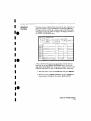
Your measurement. then, requires verification of the sequential
addresses the microprocessor looks at, and of the data in ROM at
these addresses, If the reset vector fetch IS correct un this example l,
you WIll see the following list of numbers III HEX (default beset
when YOUI' measurement results are displayed.
+ 0000 000000 0000
+ 0001 000002 04FC
+ 0002 000004 0000
+ 0003
+ 0004
000006 8048
008048 3E7C
This list of numbers will be explained in detail later in this chapter
in "The State Listing."
••
•
•
Using the State Analyze,
6-3
How Do I
Configure the
Logic Analyzer?
In order to make this state measurement, you must configure the
logic analyzer as a state analyzer. By followmg these steps you will
configure Analyzer 1 as the state analyzer.
If you are in the System Configuration menu you are m the right
place to get started and you can start wrth step 2; otherwise, start
with step 1.
1. Using the field m the upper left corner of the display, get the
System Configuration menu on screen.
a. Place the cursor on the field in the upper left corner of the
display and press SELECT.
h Place the cursor on System and press SELECT
e•I
I
2 In the System Configuration menu, change the Analyzer 1 type
to State If Analyzer 1 IS already a state analyzer, go all to
•
step 3.
a. Place the cursor on the Type:
and press SELECT
b. Place the cursor on State and press SELEC'f.
sus t em runr tuure t tnn
Analll"""- 1
neme
16'l!:.IIj(ISTtHE I
T~PE
I
une s s i qne c FOld,
Type
stet e
I
Oft
I
Pod 4
U BtU tt rtf tIt t
Pod 5
Htt1t!1t ttt
Pod
I
IlttltttttttHttt I
1
suo '
rr rrnrrr unnt
Pu d :':
I
tn t
I
e.
•
•
•
•
e.
I
Using the State Analyzer
6-4
•
I
I
I.
I
•
•
•
••
•
•
•
•••
3. Name Analyzer 1 68000STATE ropt.ional l
a. Place the cursor on the Name:
field of Analyzer 1
and press SELECT.
b. WIth the Alpha Entry pop-up, change the name to
68000STATE rsee "Alpha Entry Pop-up Menu" in chapter 4
if you need a remmder).
4. Assign pods I, 2, and 3 to the state analyzer.
8"
Place the cursor on the Pod 1 field and press SELECT.
b. In the Pod 1 pop-up, place the cursor on Analyzer 1 and
press SELECT.
c. Repeat steps a and b for pods 2 and 3.
I
•
Using the Slale Analyzer
6·5
Connecting
the Probes
At this point, If you had a target system with a 68000
microprocessor, you would connect the logic analyzer to your system.
Since you will be assigning labels ADDR and DATA. you hook the
probes to your system accordingly
• Pod 1 probes 0
D15.
• Pod 2 probes 0
A15
• Pod 3 probes 0
A23.
• Pod 1, eLK (J
Activity
Indicators
through 15 to the data bus lines DO through
through 15 to the address bus hnes AO through
through 7 to the address bus lines AlB through
clockI to the address strobe (LASI.
When the logic analyzer is connected and your target system is
running, you will see: in the Pod I, ::!, and 3 fields of the System
Configuration menu. This indicates which signal lmes are
transitioning;
System rnnr rnure t ren
Anllly~er
Analyzer 2
1
flame
II5eOQI)STflTE I
Type
,
State
unee sicneo Pods
rqp s
I
III
r
Pod 4
__iU--tUtUtii
Pod 5
Pod
UiUUUttU,tt
I
I ttttlttttttttrt~
Pod'
IIl;TIVITt
ItUtlttlt~ltHIt
I
I
I
t-nrnrnUttH
Using the State Analyzer
6·6
Po" ,
INDICAmRS
•
•
e•I
•
•
e.
•
•
•
•
e.
•
•
•
•
'.
•
•I
•
••
•
•
•
•••
I
I
Configuring
the State
Analyzer
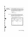
Now that you have configured the system, you are ready to configure
the state analyzer. You will be:
• Creating two names rlabels: for the input signals
• Assigning the channels connected to the input signals
• Specifying the State (Jl clock
• Specifying a trigger conditron
L DIsplay the STATE FORMAT SPECIFICATION menu
a. Press the FORMAT key on the front panel,
2. Name two Labels, one ADDR and one DATA.
a Place the cursor on the top field in the label column and
press SELECT.
b. Place the cursor on Modify label and press SELECT
16bOCilISTftTEI- STATE rOIi':MIH SPECIFICATION
I
In I
Hctl'Jlty
~
~
~
Pol
POD
s
POD :'
POD I
II [~:~I II (~~,
······.. 11"'·····..·· ··11 "'
[i~~b
t r r r r r t r t rt r r i r
15
( specify 5lJmbols )
a7
I)
UUlstHHtlUl
15
87
"
ttttttt1ttttttli
15
87
I)
I
1
~
~
~
~
~
L..:.Q..!..!..:
Using the State Analyzer
6-7
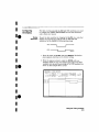
c. With the Alpha Entry pop-up, change the name of the label
to ADDR (see "Alpha Entry Pop-up Menu" in chapter 4 if
you need a reminder)
d. Name the second label DATA by repeating steps a through c
3 Assign Pod 1 bits 0 through 15 to the label DATA
B.
Place the cursor on the bit assignment field below Pod 1 and
to the right of DATA and press SELECT_
b Any combination of bits may already be assigned to this pod:
however, you will want all 16 bits assigned to the DATA
Label. The easiest way to assign is to press the CLEAR
ENTRY key to un-assign any asstgned bits before you start
Co
Place the cursor on the penod under the 15 in the bit
assignment popup and press SELECT. This will place an
asterisk in the pop-up for bit 15. indicating Pod 1 bit 15 is
now assigned to the DATA label. Repeat this procedure until
all 16 bits have an asterisk under each bit number. Place the
cursor on Done and press SELECT to close
the pop-up.
d Repeat step c for Pod 2 and tbe ADDR label to assign all
16 bits.
e" Repeat step c except you will assign the lower eight bits
10 - 71 of Pod 3 to the ADDR label.
I
•
e-
•I
I
•
e.
•
•
•
•
e.
I
Using the State Analyzer
6-8
•
I
I
Ie
I
•
•
•.e
c~
Specifying the
J Clock
If you remember from "What's a State Analyzer" in Feelmg
Comfortable l-~rith Logic .4nalyzers, the state analyzer samples the
data under the control of an external clock. which is "synchronous"
WIth your circuit under test. Therefore. you must specify which clock
probe you will use for your measurement. In this exercise, you will
use the J clock, which is accessible through pod 1.
1. Select the STATE FORMAT SPECIFICATION menu by pressing
the FORMAT key.
~.
Set the .J Clock to sample on a negative-going edge.
8.
Place the cursor on the
and press SELECT.
b. Place the cursor on the box just to the right of J
up (labeled OFF' and press SELECT.
III
the pop-
c Place the cursor on I and press SELECT.
d. Place the cursor on Done and press SELECT.
16oC"JU5THTE1- STATE FOilMAT SPECIFICATION
( snee iru S!!mbols: )
CLOCI
I
•
•
•.e
eWeK field
.n
I
I
eoc
POD 3
He t I 'I \ t'l
~
~
~
~
~
SpPflly
,
(111(~
neue
,
JI
P~E Jf+
r+
I
[}]LWI1[}]NITJ
POD
I
TTL
Cion
HIUllt1l111rt
e-
..............
c
,.
f-!..-
1-7-
l-
r-=@g-=
-IJI f-
~
~
~
I
•
Using the State Analyzer
6-9
Specifying a
Trigger
Condition
To capture the data and place the data of Interest In the center of
the display of the STATE LISTING menu, you need to tell the state
analyzer when to trigger. SInce the first event of interest is address
0000. you need to tell the state analyzer to trigger when it detects
address 0000 on the address bus.
1 Select the STATE TRACE SPECIFICATION menu by pressing
the TRACE key.
2, Set the trigger so that the state analyzer tnggers on
address 0000.
a. PLace the cursor on the 1 in the Sequence Levels field of
the menu and press SELECT.
loaoUUSTATE 1- stare U'RCE SPECIFICIITION
rr er e nooe
I
Sing I e
I
arrneu "y
6
I Inser t Lei';' I
I rr i
~
Sequence t eve t 1
IIhll
e
vt nr r nq
ggel' on II e
r
I
net e t e t eve
I enu st et s
I c=::JJ
j
I
t me s
1
~
enche e
-~
olin'
~
, tore
till:==J
Labe I
B~;e
I
~~
e
1["'L":lIlol~
D
~~
r
o
~~
I ~~
b. Place the cursor on the anystate field to the right of the
Trigger on field and press SELECT. Another pop-up
appears showing you a list of "trigger on" options. Options a
through h are qualifiers" You can assign them a pattern for
the trigger specification.
Using the State Analyzer
6-10
•
•
_.
•
•
•I
-.
•
•I
I
-.
•
•
I
I
Ie
I
I
c. Place the cursor on the a option and press SELECT
d. Place the cursor all Done in the Sequence Levels pop-up and
press SELECT.
e. Place the cursor on the field to the right of the a under the
label ADDR and press SELECT.
f. With the keypad, press 0 (zero) until there are all zeros in the
Specify Pattern: pop-up and then press SELECT.
Your trigger specification now states: "While storing anyatate,
trigger on "a" once and then store anystate."
•I
16,,'"lIISTHTE
1- STATE
mnde I
SIngle
'tre o-
IHIII~
I
sequence Levels
r tcrinq enust sta :
TI-lgge," 01' "e
I
11rnlea
I
t Ime·=
'y
PII~
I
51-el'l[h,'o
I
Ott
I
[01.11'11
I
.e
I
I
I
I
H'ACE SP[[IfICATION
Of r
r re st or e
Oil
I
I
~
I
I
I
When the state analyzer is connected to your circuit and is
acquiring data. it continuously stores until It sees 0000 on the
address bus, then it will store anystate until the analyzer memory is
filled.
.I
I
Using the State Analyzer
6·"
=
=
Acquiring
the Data
Since you want to capture the data when the rmcroproceasor sends
address 0000 on the bus after power-up, you press the RUN key to
arm the state analyzer and then force a reset of your circuit. When
the reset cycle ends, the microprocessor should send address 0000.
trigger the state analyzer and switch the display to the STATE
LISTING menu.
We'll assume this IS what happens in this example. SInce the odds
that the microprocessor won't send address 0000 are very low.
16i3Ii'JlbTHTE
-,." ""
1- STATE
11(189J6
lIoa9.:'E
6U:;C
-UUIJO
»oasao
811J[
-000-1
"OO~F"I
8""0
-OO'E
, ,(lI)>1F5
59,1)
-1-11-11'.:'
()(JOq~H
"IEFI'I
-IJe":'1
1")6Q~[
..
Itni]o,-,I
111)1:11101)
~'l,":11
'1('CII..lO~
ffiL"j.:'
'''V:'I'('..:!
uocuce
+11
I
;;;t}
H"~I05
1
H'o06
'·"'0"-:1(
O-lF(
tOU07
'" 'o"-'lE
61 D6
61 '-'0
'H:"l['o
nn6
"5U
RESET VECIDR FETCH ROUfINE
60~D
'::E,[
1.")611-'10
"_'~"-'lH
•I
61FH
tUUO-l
e·I
I
LI'iTWG
-(":11)5
I
I
,."."".,
Now IS the time to load the state measurement demo file from the
disc if you wish. The file name is STATEDEMO. Follow the
procedure III Appendix B to load the file
e.
I
•I
I
e.
I
Using the State Analyzer
6-12
•
I
I
Ie
I
I
I
I
.e
•
•I
L
The State
Listing
-
The state listing displays three columns of numbers as shown:
166Cllll',TIHE
1- STOTE
LISTINli
Oil
Lebe I
Base
'1069::-6
ooesce
E10:!C
-coos
61FA
IIn69}1J
BI),[
-uuu-t
llOuclF4
[11)(":'
-DO')}
nOO-lF6
110Cl9;:F<
019::'0
-(IOI:(:!
-(JOI)1
1)l)e9::!C
FF9R
1+\1011111
+001)'1
1)1)1]'-11)0
nooo
-1)(1("7
-0006
wOO.:!
+(lOO}
110000"
uOl)uO-!
ooorce
-l1=:FR
O'iFC
eeoc
8°-18
+001)..j
'_"10046
tuOU5
IJ08u4k
coon
to006
IJoao4C
rllJo''''1E
0001050
61D8
+uO(l7
tuO')5
2E"iC
O~FC
6100
I
STATE LOCATIONS
The first column of numbers are the state line number locations as
they relate to the trigger point The trigger state is on line + 0000
in the vertical center of the list area. The negative numbers indicate
states occurrmg before the trigger and the posrtive numbers indicate
states occurrmg after the trigger.
The second column of numbers are the states (listed In HEXI the
state analzyer sees on the address bus. This column IS labeled
ADDR.
The third column of numbers are the states (listed in HEX' the state
analyzer sees on the data bus. This column is labeled DATA_
I
.e
I
•
Using the State Analyzer
6·13
Finding the
Answer
YOul' answer is now found in the listing of states + 0000 through
+0004.
The 68000 always reads address locations 0, 2, 4, and 6 to find the
stack pointer location and memory location for the Instruction it
fetches after power-up. The 68000 uses two words for each of the
locations that it 18 lookmg for, a high word and a low word.. When
the software designer programs the ROM, he must put the stack
pointer location at address locations 0 and 2. 0 IS the high word
location and 2 is the low word location. Similarly, the high word of
the mstructton fetch location must be in address location q and the
low word in location 6
Since the software design calls for the reset vector to
L Set the stack poi nter to 04FC
2 Read memory address location 8048 for Its first instruction
fetch, You are interested in what IS on both the address bus and
the data bus in states 0 through 3. You look at the following
listing and see that states 0 and 1 do contain address locations
o and 2 under the ADDR Label, indicating the microprocessor
did look at the correct locations for the stack pointer data. You
also see that the data contained in these ROM locations are
0000 and 04FC, which are correct,
Yim then look at states 2 and 3, You see that the next two address
locations are 4 and 6, WhICh is correct, and the data found at these
locations is 0000 and 8048, WhICh is also correct.
+ 0000
+ 000 1
+ 0002
+ 0003
+0004
Using the State Analyzer
6·14
000000
000002
000004
000006
008048
0000
04FC
0000
8048
3E7C
•
•
e·
•
•
•
•
e.
•
•
•
•
e.
I
I
•
•
••
•
•I
•
••
•
•
•
•••
So far you have verified that the microprocessor has correctly
performed the reset vector search. The next thing you must verify is
whether the microprocessor addresses the correct location in ROM
that it was instructed to address in state 4 and whether the data is
correct in this ROM location. From the listing you see that the
address in state 4 is 008048, which is correct, but the instruction
found in this location is 2E7C, which is not correct. You have found
your problem; incorrect data stored in ROM for the microprocessor's
first inst ruction.
+0000
+0001
+0002
+000:3
+ 0004
000000 0000 thigh word of stack pointer location)
000002 GolFe (low word of stack pointer location)
0000040000 Ihigh word of instruction fetch location I
0000068048 Ilow word of instuction fetch location I
008048 2E7C tfirst microprocessor instruction)
15flIJrI(l~THTE 1- STATE LISTING
0"
-00r)7
-[l01;15
-(.lOLi5
-nl)r14
-iJOI)}
-1)0
1)2
-iJOI)1
1+-<:11;;";'01
+()III) 1
+01)1)2
+r)I)I:r3
+[l1)114
+001)5
+(10116
+(.10"7
+001:'11
0001936
IIOCJ91E
UO(j9}0
nOO..F4
O(rO-1Fil
nOli91A
IJOfi92[
IIOell11) 1)
rocona
ooooo.t
UOOuOil
n06n.:lEl
1J0ao<!F1
IIOoll<![
coaoae
roareo
eoar
61 Fli
BO}C
0000
S9,,0
4EFH
FF9H
I)I::"=,U
CI-lF[
0000
80.:18
2E7[ ........-
croo
INCOF1REGT OIlTA
O-lF[
6106
6100
I
•
Using the State Analyzer
6·15
Summary
You have just learned how to make a simple state measurement with
the HP l650A Logic Analyzer Yon have:
•
•
•
•
•
•
•
•
•
specified a state analyzer
learned which probes to connect
assigned pods l., 2. and 3
assigned labels
assigned bits
specified the ,J clock
specified a trigger condition
acquired the data
interpreted the state listing
You have seen how easy Lt 18 to use the state analyzer to capture the
data on the address and data buses. You can use this same technique
to capture and display related data on the microprocessor status,
control, and various strobe lines. You are not limrted to using this
technique on microprocessors. You can use this technique any time
you need to capture data on multiple lines and need to sample the
data relative to a system clock.
The next chapter teaches you how to use the logic analyzer as an
mteractave timing and state analyzer. You will see a simple
measurement that shows you both timing waveforms and state
listings and how they are correlated,
If you have an HP 1651A, you do not have enough channels to
Simultaneously capture all the data for a 68000_ But. since you
probably aren't workmg with 16-bit microprocessors, this example is
still valuable because it shows you how to make the same kind of
measurement on an eight-bit microprocessor
Using the Stale Analyzer
6·16
•
•
e•
•I
I
e.
•
•
•
•
e.
•
•
7
Introduction
Using the Timing/State Analyzer
In this chapter you will learn how to use the timing and state
analyzers interactively by setting up the logic analyzer to make a
simple measurement. We give you the measurement results as
actually measured by the logic analyzer, since you may not have the
same circuit available.
The exercise in this chapter is organized differently than the
exercises in the two previous chapters. Since you have already set up
both the timing and state analyzers, you should be ready to set them
up for this measurement by looking at the menu pictures.
Any new set-ups in this exercise will be explained in task format
steps like the previous chapters.
How you use the steps depends on how much you remember from
chapters 1 through 4. If you can set up each menu by just looking at
the menu picture, go ahead and do so. If you need a reminder of
what steps to perform, follow the numbered steps. If you still need
more information about "how;' use the lettered steps.
When you have finished configuring the logic analyzer for this
exercise, you can load a file from the operating system disc. This file
configures the logic analyzer the same way it is configured for this
exercise. It also loads the same data acquired for this exercise so you
can see what it looks like on screen.
In order to learn how to configure the logic analyzer, we recommend
that you follow the exercise to "Acquiring the Data" before loading
the file from the disc.
You can also compare your configuration with the one on the disc by
printing it (if you have a printer) or making notes before you load
the file.
Using the Timing/State Analyzer
7·'
Problem Solving
with the Timingl
State Analyzer
In this example assume you have designed a microprocessorcontrolled circuit. You have completed the hardware, and the
software designer has completed the software and programmed the
ROM (read-only memory), When you turn your circuit on for the first
time. your circuit doesn't work properly, You have checked the power
supply voltages and the system clock, and they are working properly.
Since the circuit has never worked before, you and the software
engineer aren't sure if it is a hardware or software problem. You
need to do some testing to find a solution.
You also notice the circuit fails intermittently. More specifically, it
only fails when the microprocessor attempts to address a routine
that starts at address 8930.
What Am I Going
to Measure?
'Ib see what might be causing the failure, you decide to start where
the microprocessor goes to the routine that starts at address 8930.
The first thing you check is whether the microprocessor actually
addresses address 8930. The next thing you check is whether the
code is correct in all the steps in this routine.
Your measurement, then, requires verification of:
• whether the microprocessor addresses location 8930
• whether all the addresses within the routine are correct
• whether all the data at the addresses in the routine are correct
If the routine is correct, the state listing will display:
+ 0000
+ 0001
+ 0002
+0003
+0004
Using the Timing/Slale Analyzer
7-2
008930 B03C
008932 61FA
008934 67F8
008936 B03C
00892E 61FA
•
•
••
•
•I
•
••
•
•
•
•
••
•I
How Do I
Configure the
Logic Analyzer?
In order to make this measurement, you must configure the lOgIC
analyzer as a state analyzer because you want to trigger on a
specific state (8930), You also want to verify that the addresses and
data are correct in the states of this routine,
Configure the logic analyzer so that Analyzer 1 LS a state analyzer
as shown:
Sys tem [onf igura t Lon
Analyzer Z
Anal !Jzer 1
Name
16EiiJ005THTE I
T~pe
I
I
coo ,
I
Pod'
UtttlUUt;tUt
ttttttttt!tTtttt
unes s i qne c POlls
Type
State
I I
I
I
all
I
eo, ,
tU--tfUtttlt
Pod s
tttttfUtttUtU
Pod ::
t - [ttl ttl tt tt t t!
Using the Timing/State Analyzer
7-3
Configuring
Now that you have configured the system, you are ready to configure
the State
the state analyzer.
Analyzer
Configure the STATE FORMAT SPECIFICATION menu as shown:
!6BIJOIlSTHTE
1- 'iTIlTE rnenar
SPEC IFrCATIOrl
( SlJecLfy Symbols )
CLOD
.n
POD ]
Hcll"IIy
~
Pol
II
er
·· ··11·
POD
~
TTL
Clod-
TTL
Clod
t titttttttttttt
tttttttttttttttl
IS
15
II
~~I
87
·
I)
II
11
POO 1
TTL
CIon
lltHfUtttttttt
15
6,
0
1
~
I -Otf-
I
=~:~ =
I
I -Ott-
~
Configure the STATE TRACE SPECIFICATION menu as shown:
!6dfiOI1STIHE
1- STATE
5 Lng! e
TI1ACE SPECIfICATION
I
Armed by
'iequence Levet s
un 11 e S 101" mq 'enqs t et.e
, lJm~~
'rriqqe r 01'1 e
I
5 t or e
I
6
~ Ily"
tat e
Run
I
er encues
Of'
I
[own!
I
Time
I
er e ster e
I
t.eb e I
ae ee
Il
Using the Timing/State Analyzer
7·4
~IOHTH
I
~~
IIICI6Q301~
~~
~~
1\.'J",;u\.'I~
Off
•
e·
.'
•
•
•
e.
•
=~;:=
'tr ec e norte I
•
I
•
•
•
e.
I
I
I
I
Connecting
the Probes
·e
•
•I
•.e
At this point, if you had a target system with a 68000
microprocessor, you would connect the lOgIC analyzer to your system.
Since you will be assigning labels ADDR and DATA, you will hook
the probes to your system accordmgly.
• Pod 1 probes 0 through
Di5
• Pod 2 probes 0 through
A15
• Pod S probes 0 through
A2:J
• Pod 1, eLK (J clock) to
15 to the data bus lines DO through
15 to the address bus lines Ao through
7 to the address bus lines A16 through
the address strobe ILASI
L
Acquiring
the Data
Since you want to capture the data when the microprocessor sends
address 8930 on the bus. you press the RUN key to arm the state
analyzer. If the microprocessor sends address 8930, it will trigger the
state analyzer and switch the display to the STATE LISTING menu
We'll assume this is what happens in this example.
I
•
•
•.e
•
•
Using the Timing/State Analyzer
7·5
Finding the
Problem
You look at this listing to see what the data IS in states +0000
through +0004_ You know your routine is five states long.
The 68000 does address location 8930, so you know that the routine
IS addressed, Now you need to compare the state listing wrth the
following canoed addresses and data·
+ 0000
+0001
+ 0002
+ 0003
+ 0004
008930
008932
008934
008936
00892E
B03C
61FA
67F8
B03C
61FA
As you compare the state listing {shown below' with the above data,
you notice the data at address 8932 is Incorrect Now you need to
find out why.
t.ebe i
6~~~
~cc
-ODCI6
-ooce
[JU66Ct'l
0068[[
ooeecs
-oocc
-mliJ-l
Q068FE
006900
---I1(10~
OllCI:'8-l
1+00001
000255
0069::;0
-ucoI
+11,":11
on69~.::!
':'r:'FF
5710
.:IBE7
<.jE75
aooo
0000
6910
B'll[
UUFF.......157F15
+OC"J~
ooog::;-I
+n(10~
+,-,00..j
Ou5935
Ou69.2E
-ooos
151Ft=<
00593u
BU,[
+u006
+000,
Ouu:'!J-1
I'F"):,65
B9~,'
+IJOO/i
OCJ89.2ii
-1EFi1
BOle
UI)'II-,
II~CORRECT
DAfA
•
•
e·
•
•
•
•
e.
•
•
•
•
e.
I
Using the Timing/State Analyzer
7-6
•
I
I
Your first assumption is that incorrect data is stored to this memory
location Assume this routine is in ROM since it is part of the
operatmg system for your circuit. Since the ROM is programmed by
the software designer. you have the software designer verify whether
or not the data at address 8932 IS correct, The software designer
tells you that the data is correct. Now what do you do?
Ie
I
I
I
•.e
•
•
•
•.e
•
•
Now it's time to look at the hardware to see if it is causing Incorrect
data when the microprocessor reads this memory address. You decide
you want to see what is happening on the address and data buses
during this routine in the time domain.
[0
order to see the time domain, you need the trmmg analyzer.
c
What Additional
Measurements
Must I Make?
Since the problem exists during the routine that starts at address
8930, you decide you want to see the timing waveforms on the
address and data bus when the routine IS running; You also want to
see the control signals that control the read cycle. lOU WIll then
compare the waveforms WIth the timing diagrams in the 68000 data
book.
Your measurement, then, requires verification of:
• correct timing of the control signals
• stable addresses and data during the memory read
The control signals you must check are:
•
•
•
•
•
system clock
address strobe (AS)
lower and upper data strobes (LDS and UDS I
data transfer acknowledge lDTACKl
read/write lRIWI
Using the Timing/Stale Analyzer
7·7
How Do I
Re-configure the
Logic Analyzer?
In order to make this measurement, you must re-configure the
Configure the logic analyzer so Analyzer 2
shown:
IS
a tunmg analyzer as
'iystem r ont Iqer-e t a on
AOlll uaer I
Amllyzer 2
rl ~~II'
16o l l0nsTATEJ
Type
I
I
si ete
Neme
16Ijl)I:IIITlm,IGI
Type
I
rnm nq
( Auto-scale 1
PCO
,
1,11 Itt n t rr r t r r r r
Pod
Pod -1
111- -II n l i l t !
I
Pod 5
I,HlltLUtUU1U
rllltltlttUUU
soo
Connecting the
Timing Analyzer
Probes
lOgIC
analyzer so Analyzer 2 is a timing analyzer. You leave Analyzer 1 as
a state analyzer since you will use the state analyzer to trigger on
address 8930.
At this point you would connect the probes of pods 4 and 5 as
follows:
•
•
•
•
Pod
Pod
Pod
Pod
• Pod
• Pod
• Pod
• Pod
Using the Timlng/Slale Analyzer
7-8
4:
4
4
4
4:
4
5
5
bit
bit
bit
bit
0
1
2
3
to address strobe (AS)
to the system dock
to low data strobe ILDSI
to upper data strobe IUDSI
bit 4 to the read/write IRfWJ
bit 5 to data transfer acknowledge (DTACKI
bits 0 through 7 to address lines AO through A7
bits 8 through 15 to data lines DO through D7
•
•
e
•I
•
•
e.
•
•
•
•
e.
•
I
•
I
•
••
•I
I
•
••
•I
I
I
••
I
I
Configuring
the Timing
Analyzer
Now that you have configured the system, you are ready to configure
the timing analyzer.
Configure the TIMING FORMAT SPECIFICATION menu as shown:
16EiUO(lTIMf~G 1- TIMING FOFnAT SPECIFICATION
PODS
TTL
Retl'llty
----------------
Lene r Pol
15
a-
I
( Specify Symbols
PO[J~
TTL
__ttt--ttr---r15
I
8,
I~~
;~~:';
[LOO
+
IJtiTH
-.: .
........
.~ ... "".
-011-011-
-nr r-0((-
-01/-
-011-
Configure the TIMING TRACE SPECIFICATION as shown:
16EiOW0THIIH,
1- TItuN6
rr ec e model
Slngl~
Armed
by
TI>1AC[ SPEClF[(ArION
I
!obUC,,15TIlTE I
",(qUJ;,l ti on mode I Tr~II' 1 t i c ne l
Leba I
~~~~IDTH[f· 1lE.Ii.L::J1BffiD~
Be" e
~~c::8i==:JI~~~~[[u
Fl
no
Pe t t er n
I
c::=:J==I=:::J==c::2:Jr::::ICJ
D I ,;n 11;
pr-eee n t lor
then r i no
'''g, c:::=::Jc:::=::Jc:::=::JI==:Jc:::=::Jc:::=::Jc:::=::Jc:::=::J
Using lhe Timing/Slale Analyzer
7-9
Setting the
Timing Analyzer
Trigger
Your timing measurement requires the timing analyzer to display
the timing waveforms present on the buses when the routine IS
running. Since you triggered the state analyzer on address 8930, you
want to trrgger the timing analyzer so the timing waveforms can be
time correlated with the state listing.
I
I
e·
•
•
•
•
STATEANAL"ER}-4~E~~e.
•
•
•
•
e.
Th set up the logic analyzer so that the state analyzer triggers the
timing analyzer, perform these steps:
1. Display the TIMING TRACE SPECIFICATION menu.
2 Place the cursor on the Armed by
SELECT
field and press
3_ PLace the cursor on the 68000STATE option in the pop-up and
press SELECT.
Your timing trace specification should match the menu shown;
!6dilODTI11rlG 1- rrMING TrRCE SPECIrI[flTlON
AR.MS TIMING
'rr ece model SIngle I
r-me d b~ 16a'")OSTtHEI
ucqurs r t i on model Trerr,LtlunalI
ANAL~;:ER
ICLOD
Finn
p~
rue»
1E:::JlbQL:Jl!ill.L:JloTHO
1~§QQOI[lHTr+
I
~~[Jk::::J~~c:E:f::::::J~c:E::LJ
Ba,e
t tern
1 Hid
euoe
c::=Jc::=Jc::=Jc::=Jc::=Jc::=Jc::=Jc::=J
I
Using Ihe Timing/Slale Analyzer
7-10
•
•
•·e
•
•I
•.e
I
I
I
•.e
•
•
W
.~• •\L1@i"
Time Correlating
the Data
In order to time correlate the data, the lOgIC analyzer must store the
timing relationships between states" Since the timing analyzer
samples asynchronously and the state analyzer samples
synchronously, the logic analyzer must use the stored timing
relationship of the data to reconstruct a time correlated display.
To set up the lOgIC analyzer to keep track of these timing
relationships, turn on a counter in the STATE TRACE
SPECIFICATION menu The following steps show you how:
1 Display the STATE TRACE SPECIFICATION menu
2. Place the cursor in the field just below Count on the right Side
of the display and press SELECT.
3. Place the cursor on the Time option and press SELECT. The
counter will now be able to keep track of time for the time
correlation.
1660r:J1:ISTHTE
1- STATE
'rr ece mode I
':; lnq I E
HlACE SPECIFICATION
I
Sequence tevets
Hh r l e s t ormn enust et e'
,
Trlgger nn
I , II~I!;:
6
,
arneo
I
DI.I
PUll
I
BI-~n~h~-
STore
euqs t et e'
I
011
I
t oun I
I
Tlm..
I
Pre; tore
I
t.ene I
ee se
,
n
I
r
d
~IDHTH
UtI
I
I
~~
IOOB931)i~
I~'"I-~"I~
I'JllJl:.'~i~
I I:I"")-\\!I~
Using the Timing/State Analyzer
7-11
=~,~~-
Re-acquiring
the Data
=
-=:::r-----------------After you connect the probes of pods 4 and 5 to your circuit, all you
have to do is press RUN. When the logic analyzer acquires the data,
it SWItches the display to the STATE LISTING menu unless you
switched one of the other menus to the timing analyzer after
reconfigurmg the STATE TRACE menu. Regardless of which menu is
displayed, change the display to the Mixed mode.
Now is the time to load the mixed measurement demo file from the
disc if you wish. The file name is MIXEDDEMO. Follow the
procedure in Appendix B to load the file.
==,=====r---------------Mixed Mode
Display
The Mixed mode display shows you both the STATE LISTING and
TIMING WAVEFORMS menus simultaneously, Tb change the display
to the Mixed mode:
1 Place the cursor on the field in the upper left corner of the
display and press SELECT
2 Place the cursor on Mixed mode and press SELECT.
You will now see the mixed display as shown.
IM1'ed mod~l- Di'lplll!l
L~b~l
aes e
Tlm~
~~
01·169nO
cone
CII10>iF -1
OOOCi
OUO,"F6
i:l930
[J1169~O
EJ03C
(lLI59::2
IIOFF
-IJOOJ
-CiCIO..:'
-IiOOl
I+Wlonl
+1:"1('I
+1)(J02
+{)I)O"
OLJ69::--1
I
P~l
I 24 IJ
I
Ei7F6
eo-r
on59::-6
68000TIMNG
S~I '01'_'
6601l0STATE- 'iTATE LI5TItiG
~~I
I
DelBy
u
.2~
2.:j
.20
2.:j
2.:j u
10 Trigger
- TIMING i'lAVEFORtfS
5flol ~I,
~>i
I
1
I
I
I
I
o to 'tr r qqer
1--c4
S6 ua
I
I-:.:'.:j ae uz
I
•
•
e·
•
•
•
•
e.
•
•
•
•
e.
I
Using the Timing/State Analyzer
7-12
•
I
I
Ie
I
I
•
•.e
•
•I
•.e
•
•
L~#:\
Interpreting
the Display
In the Mixed mode display the state hsting is in the top half of the
screen and the timing waveforms are III the lower half. The
important thing to remember IS that you time correlated this display
so you could see what is happening in the time domain during the
faulty routine.
Notice that the trigger point in both parts of the display LS the same
as It was when the displays were separate, The trigger in the state
listing is in the box containing +0000 and the trigger of the timing
waveform is the vertical dotted line.
As you look at the rmxed display, you notice nothmg wrong except
the data at address 8932 is incorrect However, you are seeing only
one bit each of the address and the data. To see all the data and
addresses in the timing waveform part of the display, you must
overlap them
IMi-ed mode
]
ee ,8
L~lJ~
681100STATE- SHlfE LISTING
He.
~£jl
,'"
OOe90l)
3uOO
Time
,
H,~_,'
-OC".!::
OuOO
-001,]
U(lOclF5
51J3l1
1~i1,~,uol
008930
uOe932
OOe9301
eU3C
+(01) I
+000::
(lUFF
51FEI
~uulJ3
(108916
Bn3C
S8crOI'1
,.
~
u ,',
,
OTI~U
2~
us
14 us
2B us
us
us
I
" ee
eo "'
ua I
"
a
~
68000TIMNG
IlLOO, OU
- TIMING
I
us
,, "24 us
,,
,"
"
,
OOO.jF~
-or;II':2
1
500 ns
HRVEFO~MS
I
De]
ey
"
'< to rrrqqer
0
to Tr 19ger
I
I
Of'
''"
~
"
1- Displlllj
r)',
-u,
Using the Timmg/State Analyzer
7-13
Overlapping
Timing
Waveforms
•
Smce you -see--nothing wrong with the timing waveforms 80 far, you
think unstable data may be on the data lines during the read cycle
In order to see unstable data, you must be able to see all the data
lines during the read and look for transitions Overlapping the
waveforms allows you to do this, Th overlap waveforms, follow these
steps.
1. Place the cursor on the 00 of the ADDR 00 label and press
SELECT The followmg pop-up opens in which you specify the
bit or hits of the address bus you want to overlap.
2 Rotate the KNOB until all is displayed and press SELECT All
the address bits WIll be overlapped on one line.
3, Repeat step 2 except overlap the data bits.
Bit select
Done)
811
lt1l~ ,j
•
•
e.
--•
i
LIsr'
,
•
•
•
":i~ e.•
•
mude
Label
aeae
D1spln,
tiOllIW5TATE- STATE
'~E:' y m t select
~
'~
-QUO:;
000900
::
....)Uo::'
oon~F.j
'),'-_...,....,...
-01101
1+00001
+0001
+0002
+0003
Ooo.-F5
0089]0
0089:;1
C":1SgJ.J
a930
coease
66000TIMNIi
sec nuv
Using the Timing/Slate Analyzer
7·14
1-
•
1
-
all
-'
2'- u"
2"
I:103C
OUFF
u~
26 us
2-'1 u"'
2<1 us
67F6
B(J3C
l' 1.0 frlgger
TIMING IolRVEFOl!MS
5':10 os
1
Delay
I
(I
~
I
01.0 frlgger
1-::,.1
1-::,.1
Eia us
ea us
1
1
•
•
•
••
•
•
•
•
••
•I
•I
Finding the
Answer
As you look at the overlapping waveforms. you notice there are
transitions on the data lines during the read cycle, indtcatmg the
data is unstable You have found the probable cause of the problem
in this routine. Additional troubleshootmg of the hardware Will
identify the actual cause
11'Ii ~d moue Iw DisplllY
-oocc
66Cll10".iTATE - STATE
==1
~~
I)Oa911\"1
,nUll
-1)1)0,"
1)IIi:l-1FLi
oooo
-ouot
l)nO~F6
69,lJ
1+110001
ocecco
+<)00~
l)IolJgJ:2
QuegJ'!
+<)003
OoagJI5
+<)1)(1 I
660(lOTIMN6
LI5Tn~li
Ejlj::;[
(II:)FF
67F6
60:;(
- TInING NRVEfOi!nS
• to Trigger
I
o to Trigger
1-1.:1 6C1
2.:1 sa IJ~
II';
I
I
t
UNt.TABlE DATA
••
•
•
Using the Timing/State Analyzer
7-15
III\£M1'
Summary
You have just learned how to use the timing and state analyzers
interactively to find a problem that first appeared to be a software
problem, but actually was a hardware problem
You have learned to:
•
•
•
•
trigger one analyzer with the other
time correlate measurement data
interpret the Mixed mode display
overlap timing waveforms
If you have an HP 1651A, you do not have enough channels to
simultaneously capture all the data for a 68000 But, since you
probably aren't working with 16-bit microprocessors, this exercise is
still valuable because it shows you how to make the same kind of
measurement on an eight-bit microprocessor.
Using the Timing/State Analyzer
7-16
•
•
e·
•
•
•
•
e.
•
•
•
•
e.
•I
I
I
8
iW
•
I
I
I
I
I.
I
I
I
I
Making Hardcopy Prints
PW%··'lil@i'·il@'!it¥i'l'i''!tfi
Introduction
The HP 1650AJ51A Logic Analyzers allow you to print the
configurations, waveforms, and listings. Whenever your printer is
connected to your logic analyzer and you instruct it to do so, it will
print what IS currently displayed on screen,
This chapter shows you how to set up the logic analyzer's RS·232C
interface for printers If you have a Hewlett-Packard ThinkJet,
QuietJet. or ThinkJet serres printer, the RS·232C mterface is
already set up for you, If you have another kmd of printer, refer to
your printer manual for its interface requirements and change your
Logic analyzer's interface configuration as instructed
wI,"
I
"""
Hooking Up
Your Printer
,
,f·"
.,1"
If your printer IS already connected to the logic analyzer. skip to
"Setting RS·232C for HP Pnnters" on the next page" If not, hooking
up your printer is just a matter of havmg the correct RS·232C
interface cable for your printer and logic analyzer:. Refer to the
Setting Up The Logic Anal~l'zer Guide you received with your logic
analyzer.
••
I
I
Making Hardcopy Prints
8-1
-
Setting RS-232C
for HP
Printers
All you have to do to set the interface for any of the previously listed
Hewlett-Packard series printers IS to set the printer type in the
RS-232C Configuration submenu.
To set the printer type, follow these steps.
1 Display the 110 menu by pressing the 110 key.
2 Place the cursor on RS-232C Configuration and press
SELECT
You will see the following submenu:
RS-l31[ [ONF [GURAlION
Pr oto r ol
I
~Ofl, "OFF
510p 61 t s
P~r
I ty
BellD r e te
aone
I
96'K!
Peper ~n dHI
I~
3. Place the cursor in the Printer:
field and press
SELECT. The pop-up opens showing you the printer choices.
4. Place the cursor on the printer series type and press SELECT.
5 Place the cursor on Done and press SELECT The logic
analyzer will display the menu that was displayed when you
selected the 110 menu.
•
e·
•
•
•I
e.
•
•
•
e.
•
I
Making Hardcopy Prints
8-2
•
•
•
••
•
•
•I
••
I
•
•I
Setting RS-232C
for Your Non-HP
Printer
The following attributes of the RS-232C mterface must be set to the
COITect configuration for your printer:
• Protocol
• number of data bits
•
•
•
•
number of stop bits
parity type
Baud rate
paper width
You can set all of these attributes for your printer by following this
procedure
L Press the 110 key to displsy the 110 menu.
2" Place the cursor on R8-232C Configuration and press
SELECT.
3. Place the cursor on the attribute and press SELECT.
4. When the pop-up is open, place the cursor 011 the option your
printer requires and press SELECT. The pop-up doses, placmg
your selection In the box Repeat this step for all attributes
that you need to change.
5. Place the cursor on Done and press SELECT, The lOgIC
analyzer will display the menu that was displayed when you
selected the lIO menu
••
I
I
Making Hardcopy Prints
8·3
4
Starting the
Printout
When you are ready to print, you will need to know whether there is
more data than is displayed on screen. In cases where data is off
screen Ii.e., format specifications wrth all pods assigned to a single
analyzer), you need to decide whether you want all the data or just
the data that is on screen
[f you
want just what is on screen, start the printout with the Print
Screen option. If you want all the data, use the Print All option
Both options are in the I/O menu
Once you decide which option to use, start the printout by plecmg
the cursor on the print option rscreen or all: and pressing SELECT,
I/O MENU
• Exit
• Print Screen
• Prmt All
• Disc Operations
• RS-232C Configuration
• External BNe Configuration
• Selftests
Print Screen
Making Hardcopy Prints
8·4
The Print Screen option prints only what is displayed on screen at
the time you imtiate the printout" In the Print Screen mode. the
printer uses its graphics capabilities so the printout will look just
like the lOgIC analyzer screen with only one exception: the cursor
will not print.
•
•
e·
•
•
•
•
e.
•
•
•
•
e.
•
•
•
Print All
•·e
•
•
•
•.e
•
•
•
•.e
•
•
The Print All option prmts not only what IS displayed on screen,
but also what is off screen at the time you initiate the prmtout. In
the Print All mode, the printout will be made in the text mode with
only one exception: a timing waveform display will be printed III the
graphics mode because it has no off-screen data.
Use this option when you want to prmt all the data in menus like:
• TIMING and STATE FORMAT SPECIFICATIONS
• TIMING and STATE TRACE SPECIFICATIONS
• STATE LISTING
4
IiIj\l\fj!/Nd!lI!:l!HI!i''lIll'l!t!'11
What Happens
during a
Printout?
When you press select to start the printout, the 110 menu pop-up
disappears, then approximately seven seconds later an advisory
PRINT in progress appears in the top center of the display. While
the data is transferred to the printer, the logic analyzer's keyboard
deactivates When the logic analyzer has completed the data transfer
to the printer, the advisory disappears and the keyboard reactivates.
Don't worry! The PRINT in progress advisory won't appear in your
printout; that's why it is delayed when you start the printout.
Making Hardcopy Prinls
8·5
_i>'_
Summary
Now that you have configured the RS-232C interface for your printer,
you can make hardcopy printouts of anything that the lOgIC analyzer
displays. This IS a valuable feature when you need to keep records of
configurations and measurements.
•
•
e·
•
•
•I
e.
I
Making Hardcopy Prints
8-6
•
•
•
e.
•I
9
What's Next?
Now that you are familiar with the logic analyzer, you may want to
try some of the basic measurements discussed in this book on your
target system. Refer to the documentation for your microprocessor.
If you are comfortable with the basic measurements that you can
perform with the HP 1650AJ51A Logic Analyzers, you are ready for
the HP 1650Al51A Reference Manual. This reference manual
explains all the capabilities of both logic analyzers and their
operation from the front panel. The reference manual also tells you
how to operate both logic analyzers from a controller via the
RS·232C interface.
What's Next?
9-1
A
Logic Analyzer Turn-on Check List
This appendix summarizes the steps you take to turn on the
HP 1650AJ51A logic analyzers. The details of the turn-on procedures
are in the Setting Up the Logic Analyzer booklet.
1. Check the rear-panel line voltage indicator for the proper
setting. Change the setting if necessary.
2. Make sure you have the proper S-wire grounded AC power
cable.
3. Make sure the rear-panel line switch is Off.
4. Connect the power cable to the rear-panel line connector and a
properly grounded power receptacle.
5. Make sure the yellow shipping disc is removed from the disc
drive.
6. Insert the operating system disc in the disc drive.
7. Turn the logic analyzer on with the rear-panel line switch.
When the logic analyzer completes its self-tests, it then loads the
operating system from the disc. When the operating system has been
completely loaded, the System Configuration menu will be
displayed.
Logic Analyzer Turn-on Check List
A-1
•I e
•
•
•
•.e
•
•
•
•.e
Loading Demo Files from the Disc
""""J'i,KIlf',,Pii"'f
: ;;;ijilf.j
To load the demo files from the
dISC,
follow these steps:
L Press the lIO key on the front panel
2. Place the cursor on "Disc Operations and press SELECT.
The disc drive indicator light will come on telling you the lOgIC
analyzer is reading the disc. When the disc is read. the lOgIC
analyzer will show you the directory of files on the disc,
3. Press the up/down ROLL key to activate the roll function,
4. Rotate the KNOB to place your file selection in the center of
the screen, The center of the screen has an arrow on each side
of the display area pointing toward the center.
When your file selection is in the center, it will be displayed in bold
type.
5. Press the up/down ROLL key again to deactivate the file
selection function
Note
Check to see what is displayed in the field m the
upper left of the menu. If Load is displa."ved, skip
steps 6 and 7.
6, Place the cursor in the field in the upper left of the menu and
press SELECT.
7 Place the cursor on Load and press SELECT. The pop-up will
close and place Load
In
this field,
I
•
Loading Demo Files from the Disc
8·1
Verify that your file selection is displayed in the box to the right of
wad from (de. If it is not, repeat step 4. If the correct file is
displayed, contmue to step 8"
8. Place the cursor on Execute and press SELECT.
The logic analyzer will load the file and display Load operation
complete. You resume normal logic analyzer operation by selecting
the menu key for the menu you want to see.
I
I
•
e.
•I
I
•
e.
loading Demo Files from the Disc
B·2
I
I