1
Simplicity 64 & Simplicity 126 INSTALLATION MANUAL.
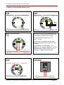
11.4 EARTH FAULTS
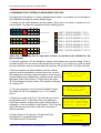
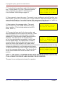
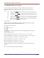
An EARTH fault indicates that something is shorting to earth
(usually through the cable screen). Disconnect the earth
screens one at a time to determine the problem line.
***
FAULT
***
Earth Fault
(Note: connecting other equipment , eg an oscilloscope , to
the panel can give an earth fault)
The voltage between battery –Ve and earth should be 14-16 volts. If it is not, the voltage should
indicate what is shorting to earth.
***DO NOT DISCONNECT THE MAINS EARTH CONNECTION. THIS WILL CAUSE A PROBLEM
WITH THE PANELS OPERATION***
11.5 DOUBLE ADDRESS
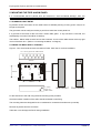
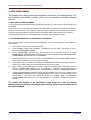
This indicates that a double address has been detected. This usually happens if a head is replaced
during maintenance, and its address has been wrongly set. The panel will report 2 fault addresses,
one will be the double address, and the other will be a missing device.
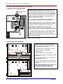
11.6 SYSTEM FAULT
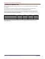
A system fault is an abnormal microprocessor running condition due to various unexpected
phenomena
This will result in the panel attempting to correct itself. Should this fault occur, the System Fault LED,
General Fault LED, General Fault relay and fault internal buzzer will be constantly active until the
control keyswitch is turned from off position to control enable position. This should cause this fault
condition to reset. If not, consult your supplier.
**Note that the system fault LED will Light if the Write enable switch is left on after entering a device
message. This is to warn of the risk of erasing the stored data. Use the keyswitch to reset after the
switch has been turned off.
11.7 PRE-ALARM
This is not a fault condition. The panel has detected a high reading from one of the devices on
the loop. This could be caused by a fire starting (in which case it acts as an early warning), or
it could be caused by a contaminated head. The panel will report the location of the problem
device, which should then be investigated.
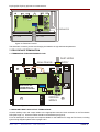
11.8 SOUNDER FAULTS
***
FAULT
***
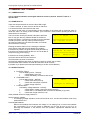
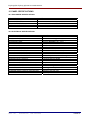
For loop powered sounders, check that all sounders are
Communicating (via device status menu), and check their
Sounder Fault
analogue value is 16. If a sounder is returning a value less
than 8, then it has detected an internal fault and should be
replaced.
If they are not communicating, then check that they have
power, and that the power is connected the correct way. If they have power, they may be damaged.
Try a replacement if available
If sounder circuit controllers (ZSCC) are used, check as follows
Check for open circuit or short circuit on the sounder line (disconnect & use a DMM).
Check cable continuity (remove from panel and measure continuity. Should read 47K)
Check that the correct END of Line resistor has been fitted. (47K – yellow, purple, orange, gold)
Check that ZSCC sounder fuses are OK (400mA TD)
If working on an existing installation, check that the devices are polarised.
Check the power supply to the ZSCC is supplying 24V (nominal).
Approved Document No: GLT.MAN-107
Issue : 1.04
Authorised: GH
Date: 05/10/2004
PAGE 21