1
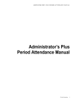
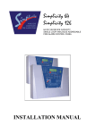
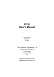
AIR
N8
CARBON MONOXIDE DETECTION & VENTILATION PANEL
INSTRUCTION MANUAL
GLT.MAN-114
ISSUE 2: DATE 31/3/05
AUTH: NJ
1
AIRCON 8 CARBON MONOXIDE DETECTION & VENTILATION PANEL – INSTRUCTION MANUAL
TABLE OF CONTENTS
1
DESCRIPTION OF THE SYSTEM
3
2
PANEL CONTROLS & INDICATIONS
4
3
CONNECTING THE DETECTORS & RELAYS
5
4
LABELLING THE DEVICES (OPTIONAL)
6
5
VENTILATION LEVELS
7
6
VENTILATION MODES
8
7
SILENCING ACOUSTIC SIGNALS
8
8
FAULT INDICATORS AND MESSAGES DISPLAYED
9
9
VIEWING INDIVIDUAL DETECTORS
10
10
DETECTOR LED CODES
10
11
TESTING THE DETECTOR WITH GAS
11
12
TECHNICAL CHARACTERISTICS OF THE PANEL
11
13
CONNECTION DIAGRAMS
12
14
GENERAL RECOMMENDATIONS
13
15
SYSTEM SET-UP CHART
14
GLT.MAN-114
ISSUE 2: DATE 31/3/05
AUTH: NJ
2
AIRCON 8 CARBON MONOXIDE DETECTION & VENTILATION PANEL – INSTRUCTION MANUAL
1. DESCRIPTION OF THE SYSTEM
The AirCOn 8 carbon monoxide detection panel is a single loop analogue addressable
system, using the Zeta Addressable protocol.
The loop is divided into 8 zones. Zones 1 to 7 can have 1 to 14 CO detectors. The
last two addresses per zone are reserved for Relay Modules (ZIOU) SEE TABLE
BELOW. These are the first & second ventilation level relays. Zone 8 can have up to
12 detectors. Any unused addresses can be used for alarm sounders, which will
activate if the CO level of any detector goes above the programmed alarm level.
The panel has one programmable ventilation level. The second ventilation level and
the alarm level are calculated according to the level of the first ventilation level.
These levels are global and apply to all 8 detection zones.
Any zone can be disabled by pressing the relevant on/off button.
ZONE ALLOCATION & DEVICE TYPE CHART
Zone 1
Zone 2
Zone 3
Zone 4
Zone 5
Zone 6
Zone 7
Zone 8
Addr
Type
Addr
Type
Addr
Type
Addr
Type
Addr
Type
Addr
Type
Addr
Type
Addr
Type
1
2
3
4
5
6
7
8
9
10
11
12
13
14
15
16
CO
CO
CO
CO
CO
CO
CO
CO
CO
CO
CO
CO
CO
CO
I/O 1ST
I/O 2ND
17
18
19
20
21
22
23
24
25
26
27
28
29
30
31
32
CO
CO
CO
CO
CO
CO
CO
CO
CO
CO
CO
CO
CO
CO
I/O 1ST
I/O 2ND
33
34
35
36
37
38
39
40
41
42
43
44
45
46
47
48
CO
CO
CO
CO
CO
CO
CO
CO
CO
CO
CO
CO
CO
CO
I/O 1ST
I/O 2ND
49
50
51
52
53
54
55
56
57
58
59
60
61
62
63
64
CO
CO
CO
CO
CO
CO
CO
CO
CO
CO
CO
CO
CO
CO
I/O 1ST
I/O 2ND
65
66
67
68
69
70
71
72
73
74
75
76
77
78
79
80
CO
CO
CO
CO
CO
CO
CO
CO
CO
CO
CO
CO
CO
CO
I/O 1ST
I/O 2ND
81
82
83
84
85
86
87
88
89
90
91
92
93
94
95
96
CO
CO
CO
CO
CO
CO
CO
CO
CO
CO
CO
CO
CO
CO
I/O 1ST
I/O 2ND
97
98
99
100
101
102
103
104
105
106
107
108
109
110
111
112
CO
CO
CO
CO
CO
CO
CO
CO
CO
CO
CO
CO
CO
CO
I/O 1ST
I/O 2ND
113
114
115
116
117
118
119
120
121
122
123
124
125
126
CO
CO
CO
CO
CO
CO
CO
CO
CO
CO
CO
CO
I/O 1ST
I/O 2ND
NOTE: ANY UNUSED CO ADDRESSES CAN BE USED FOR LOOP SOUNDERS, WHICH
WILL ACTIVATE ON AN ALARM CONDITION.
GLT.MAN-114
ISSUE 2: DATE 31/3/05
AUTH: NJ
3
AIRCON 8 CARBON MONOXIDE DETECTION & VENTILATION PANEL – INSTRUCTION MANUAL
2. PANEL CONTROLS & INDICATIONS
Aircon 8
Carbon Monoxide
Monitoring and
Ventilation System
30
50
AIRCON
75
8
100
125
150
200
250
ADDRESSABLE CARBON MONOXIDE MONITORING
AND VENTILATION CONTROL PANEL
ZONE 1
ON
1
ZONE 2
ON
ON
2
1
ZONE 3
2
1
ZONE 4
ZONE 5
ZONE 6
ZONE 7
ON
ON
ON
ON
2
1
2
1
2
1
2
1
ZONE 8
ON
2
1
2
Each zone has the following indications:
AUTO (GREEN LED):
Indicates that the zone is in auto ventilation mode
VENT (RED LED):
STEADY – a detector in this zone is above the programmed ventilation level
FLASHING – A detector in this zone was above the vent level, but is now below it. The ventilation will
continue for 5 minutes AFTER the detector drops below the vent threshold.
FAULT (YELLOW LED):
There is a fault on this zone. Check that no heads have been removed.
Each zone has the following controls:
ZONE ON / OFF
Press to enable or disable the zone.
ON
MANUAL VENTILATION START
Manual ventilation can only be started for a zone that is on (AUTO LED ON). Once the ventilation has
been started manually, the fans will be on for 5 minutes after the level has dropped below the
programmed ventilation level.
1
2
START SECOND VENTILATION SPEED
This can only be started after the first ventilation has been started (either manually or automatically).
The fans will be at their 2nd speed for 5 minutes after the level has dropped below the programmed
ventilation level.
GLT.MAN-114
ISSUE 2: DATE 31/3/05
AUTH: NJ
4
AIRCON 8 CARBON MONOXIDE DETECTION & VENTILATION PANEL – INSTRUCTION MANUAL
3. CONNECTING THE DETECTORS & RELAYS
The CO detectors, ventilation relays and alarm sounders are connected to a single
addressable loop.
Although not essential, it
may be desirable to fit loop
isolators between zones.
This will protect the loop
from total shutdown in the
event of a short circuit
appearing on the loop.
The devices (detectors, interfaces and sounders) have a unique address set via a dip
switch on the device. The address is binary, using switches 1 to 7. Valid addresses
are 1 to 126.
*** NOTE: THE SWITCH SETTINGS FOR THE CO DETECTORS ARE DIFERENT TO THE
SWITCH SETTINGS FOR THE RELAY MODULES & THE SOUNDERS. SEE BELOW***
FOR CO DETECTORS :
ON
1 2 3
4
5 6
7
8
The address setting is binary, with
the OFF position being binary 0 ,
and the ON position being binary 1.
Switch 8 is not used for setting the
address.
If you are not familiar with binary, check the
table on page 17, or use the following rule:
Switch 7 on = add 64,
Switch 6 on = add 32,
Switch 5 on = add 16,
Switch 4 on = add 8,
Switch 3 on = add 4,
Switch 2 on = add 2,
Switch 1 on = add 1.
The example shown would be:
switches 7, 5, 3 & 2
=64 + 16 + 4 + 2 = Address 86
GLT.MAN-114
ISSUE 2: DATE 31/3/05
AUTH: NJ
5
AIRCON 8 CARBON MONOXIDE DETECTION & VENTILATION PANEL – INSTRUCTION MANUAL
FOR SOUNDERS & INTERFACES:
ON
1 2 3
4
5 6
7
8
The address setting is binary, with
the ON position being binary 0 ,
and the OFF position being binary
1. Switch 8 is not used for setting
the address, but sometimes has a
device specific function. (check
instructions that came with the
device)
If you are not familiar with binary, check the
table on page 17, or use the following rule:
Switch 7 off = add 64,
Switch 6 off = add 32,
Switch 5 off = add 16,
Switch 4 off = add 8,
Switch 3 off = add 4,
Switch 2 off = add 2,
Switch 1 off = add 1.
The example shown would be:
switches 6, 4 & 1
=32 + 8 + 1 = Address 41
When all devices have been connected and addressed, turn the controls keyswitch to
the ACCESS ON position. The access LED will light. Press 3 6 9 to enter the main
menu. Select option 3 to configure the loop.
During configuration, any zone that contains a CO detector will light its green
“AUTO” LED to show that the zone contains detectors and has entered the “Auto
Vent mode” (See ventilation modes later in this manual)
4. LABELLING THE DEVICES (OPTIONAL)
As the Aircon 8 panel is analogue addressable, it has the option of giving each device (detector,
interface or sounder) a 20 character label. When an event occurs at the panel (Ventilation, alarm or
fault), the panel will display the label entered for the device, thus helping to locate the event. (The
panel will still function perfectly without any labels entered).
1. turn keyswitch to the on position and enter the access code (3 6 9)
2. Select option 4 for message editing. The panel will now ask for its write
enable switch to be set to the on position . (This is the dip switch on the
CPU board, switch 1).
Please Set The
Write Enable Switch
To the On Position
3. The panel will now ask for the loop number, and loop address of device
Message Editing
Loop:1
Address:001
being named to be entered. Press enter to confirm loop 1, and enter again
Floor 1. Row 20
to confirm address 001. Enter the device label using the built in keyboard.
Can: Exit Ent: Next
The label can be 20 characters long, so try to be as descriptive as possible.
Use the caps lock for capital letters. The delete button is used to correct mistakes. When the label has
been entered, record the device type & label in the system setup chart in the user manual. Press
enter 3 times to move to the next device (or enter the loop number and address to move forward
several places.
12 When all devices have been entered, press Cancel to exit the message
editing screen. The panel will askfor the write enable switch to be set back
to the off position .
Please Set The
Write Enable Switch
To the Off Position
NOTE: IF THE PANEL IS POWERED DOWN WITH THE WRITE ENABLE
SWITCH ON, IT WILL ERASE THE DEVICE LABELS WHEN IT IS REPOWERED.
GLT.MAN-114
ISSUE 2: DATE 31/3/05
AUTH: NJ
6
AIRCON 8 CARBON MONOXIDE DETECTION & VENTILATION PANEL – INSTRUCTION MANUAL
5. VENTILATION LEVELS
On the AirCOn 8 Analogue Addressable CO panel, there are 3 levels of ventilation.
They are First Ventilation Level, Second Ventilation Level (for use with equipment
with 2 speed fans), and alarm. For ease of use, only the 1st ventilation level can be
programmed by the user. The other 2 levels will be set automatically depending on
the level programmed for the first ventilation, according to the table below:1ST VENTILATION LEVEL
30 ppm
50 ppm
75 ppm
100 ppm
125 ppm
150 ppm
200 ppm
250 ppm
2nd VENTILATION LEVEL
50 ppm
75 ppm
100 ppm
125 ppm
150 ppm
175 ppm
225 ppm
275 ppm
ALARM LEVEL
75 ppm
100 ppm
150 ppm
200 ppm
250 ppm
300 ppm
300 ppm
300 ppm
The ventilation level programmed will apply to all 8 zones
The default value is:first ventilation level = 50ppm,
second ventilation level = 75ppm,
alarm level = 100ppm,
CHANGING THE VENTILATION (AND ALARM) LEVELS
Remember that you can only select the ventilation level, as the alarm level is set
automatically, according to the table above.
If you want to change the ventilation level, press the ventilation level button. The
yellow led will light to confirm that you are changing the ventilation level. Press
select button, and the Green Vent Level LED will change position
30 ppm – 50 ppm – 75 ppm – 100 ppm – 125 ppm – 150 ppm – 200 ppm – 250 ppm – 30 ppm etc
When the LED is at the desired ventilation level, press confirm to select it. The new
ventilation level has now been set for all 8 zones.
GLT.MAN-114
ISSUE 2: DATE 31/3/05
AUTH: NJ
7
AIRCON 8 CARBON MONOXIDE DETECTION & VENTILATION PANEL – INSTRUCTION MANUAL
6. VENTILATION MODES
The Aircon 8 Panel has the following operation modes for ventilation:•
Automatic ventilation mode: This is the mode selected during configuration.
The AUTO led will light up to confirm this status.
ON
•
(manual start) the
Manual ventilation mode-first speed: By pressing
panel will activate the first ventilation level relay for that zone. The Zone Vent
LED will flash (to show that all detectors are below the vent level). A Manual
start can only be performed for a zone that is on (auto LED on), and the relay
will stay energised for 5 minutes
1
2
•
Manual ventilation mode-second speed: By pressing
(Start Second
Speed Ventilation) the panel will activate the second ventilation level relay for
that zone. The 2nd VENT LED will be on. The second ventilation speed can
only be activated if the First ventilation is active (either from a manual or
automatic start).
•
Disconnection mode: By pressing
(Zone On / Off) the zone will be
turned off, and will not react to any signals from detectors. Its green Auto LED
will be off.
7 SILENCING ACOUSTIC SIGNALS
The Aircon 8 panel will not give an audible signal for ventilation events. This is part
of its normal operation, so it does not need to give an audible signal. It will make an
audible signal for a fault condition, or for an alarm condition.
To silence a fault signal, turn the keyswitch to on and press the silence tone button.
To silence an alarm condition, turn the keyswitch to on and press stop/start
sounders. This will turn off any sounders which are connected to the system. Then
Press the Silence tone to turn off the panel’s buzzer. Press the reset button after the
CO has cleared.
GLT.MAN-114
ISSUE 2: DATE 31/3/05
AUTH: NJ
8
AIRCON 8 CARBON MONOXIDE DETECTION & VENTILATION PANEL – INSTRUCTION MANUAL
8. FAULT INDICATORS AND MESSAGES DISPLAYED
The AirCOn 8 panel can detect the following faults:
Double Address:
This means that 2 detectors or modules have been given the same binary address. If
both the devices are detectors, the Aircon panel will light the detectors LED to
indicate the fault.
Cable (Loop) Fault:
This means that the panel has detected a fault (either open circuit or short circuit) in
the cable loop. Check the cable systematically to locate the problem.
Supply fault:
Either mains power or battery backup power has been lost. Check the supply is
present, and the relevant fuses are intact.
Earth fault:
This means that there is a short circuit between a part of the system wiring and
earth. This usually means there is a short between the one of the cables in the
detection loop and the cable screen.
Zone Fault:
This means that one of the devices in that zone has stopped communicating with the
panel, or has detected an internal fault and is reporting this to the panel. Check that
the device has not been removed, and that the device is communicating with the
panel (check the detector in the device status menu- see next section)
GLT.MAN-114
ISSUE 2: DATE 31/3/05
AUTH: NJ
9
AIRCON 8 CARBON MONOXIDE DETECTION & VENTILATION PANEL – INSTRUCTION MANUAL
9. VIEWING INDIVIDUAL DETECTORS
To view the CO level at a particular detector,
1. Turn on the access keyswitch
2. enter the menu access code (3 6 9)
3. select “Device status” (option 5)
4. press next to scroll to the desired device (or press 1 (enter) 047 (enter) to
skip to address 47 for example)
5. The screen will display:
Device Type: CO *
Value: <4 No Devs:1
====================
Loop:1
Address:001
The Value is the detector reading in ppm
The detector itself actually communicates a binary analogue value to the Aircon
panel. The analogue value responds to a ppm reading, as shown in the table below.
An.Value
ppm Value
An.Value
ppm Value
An.Value
ppm Value
8 or less
9
10
11
12
13
14
15
16
17
18
19
20
21
22
23
24
25
26
27
28
Fault value
<4
5
10
15
20
25
30
35
40
45
50
55
60
65
70
75
80
85
90
95
29
30
31
32
33
34
35
36
37
38
39
40
41
42
43
44
45
46
47
48
49
100
105
110
115
120
125
130
135
140
145
150
155
160
165
170
175
180
185
190
195
200
50
51
52
53
54
55
56
57
58
59
60
61
62
63
64
65
66
67
68
69
70
205
210
215
220
225
230
235
240
245
250
255
260
265
270
275
280
285
290
295
300
305
10 DETECTOR LED CODES
• 1 green pulse every 3 secs: correct operation
• Permanently lit up(red)-no alarm on panel: the detector has been set to the
same address as another device on the loop. Check the system setup chart to
locate the double address.
• Permanently lit up(red)- panel in alarm: the CO concentration measured by
the detector is equal or greater than the alarm level (see table for alarm level for
each ventilation setting)
GLT.MAN-114
10
ISSUE 2: DATE 31/3/05
AUTH: NJ
AIRCON 8 CARBON MONOXIDE DETECTION & VENTILATION PANEL – INSTRUCTION MANUAL
11. TESTING THE DETECTOR WITH GAS
The Zeta Addressable CO detector can be tested with a standard smoke detector test
pole fitted with a canister of Carbon Monoxide gas. The detector is an electrolytic cell
type, so the chamber is constantly monitored.
Remember that diesel vehicles do not generate CO, so can not be used to “test” the
detectors.
12. TECHNICAL CHARACTERISTICS OF THE PANEL
TECHNOLOGY
Dual 8 bit microprocessor
POWER SUPPLY
230V ac: Giving 1.1A @ 29V dc
MAXIMUM CAPACITY
8 Zones,
14 x CO zone 1-7, 12 x CO zone 8 : 110 detectors
MAX CABLE LENGTH
Depends on max. current & cable size. See table.
Maximum Loop Current (in Alarm)
500 mA
400 mA
300 mA
200 mA
1mm CSA cable
1.5mm CSA cable
2.5mm CSA cable
500 m
750 m
1000 m
625 m
930 m
1250 m
830 m
1250 m
1660 m
1250 m
1870 m
2500 m
STATUS MEMORY
Non-volatile E² PROM with 10 year data memory
VENTILATION LEVELS
8 programmable levels, 2 speed output optional
ALARM LEVELS
8 levels linked to ventilation level
VENTILATION OUTPUT
Loop Powered relay module 1A, SELV
ALARM OUTPUT
29V 50mA output (to drive relay)
Addressable sounders (on any spare address)
DIMENTIONS
355 mm x 275 mm x 100 mm
GLT.MAN-114
ISSUE 2: DATE 31/3/05
AUTH: NJ
11
AIRCON 8 CARBON MONOXIDE DETECTION & VENTILATION PANEL – INSTRUCTION MANUAL
12 CONNECTION DIAGRAMS
Zeta Input Output Unit
ZIOU
48-105
Zeta Addressable CO Detector
CO800
47-015
LOOP + IN
LOOP + OUT
4
+
+
2
N/C
CM
N/O
5
47K EOL 0.5W
6
LOOP - IN
LOOP + IN
LOOP - OUT
LOOP + OUT
Zeta Addressable Maxitone Sounder
ZAMT/R
42-007
Fyreye Loop Isolator
FEA-ISO
80-091
L1 O
UT
-IN+ +OUT
--
L1
IN
-R
L2
EARTH
LOOP - IN
LOOP - OUT
LOOP - IN
LOOP - OUT
LOOP + IN
LOOP + OUT
LOOP + IN
LOOP + OUT
GLT.MAN-114
ISSUE 2: DATE 31/3/05
AUTH: NJ
12
AIRCON 8 CARBON MONOXIDE DETECTION & VENTILATION PANEL – INSTRUCTION MANUAL
14. GENERAL RECOMMENDATIONS
1.- Do not connect the detectors to their bases until the whole building work has
been carried out and remember that once installed, power should be provided as
soon as possible.
2.- To carry out the installation, use an individual duct and avoid installing the
detector close to sources that generate electromagnetic disturbances (fluorescent
lights, engines, counters, etc.) It you cannot avoid installing them close to these
disturbances, we recommend you use shielded cable (hose)
3.- Do not use the detector base as a junction box to make connections to more than
one detector, use the terminals supplied for the cabling of the detector base.
4.- If extra holes must be drilled in the control unit cabinet, take care to clean the
cabinet of all swarf, as the conductive coating could irreversibly damage the
electronics.
5.- In compliance with the STANDARD EN 6.1010-1, 1.5mm2 monopole cable should
be used for the 220 AC connection to the control unit, protecting the input with a 5A
contactor or circuit breaker and installing it as close as possible to the control unit.
6.- The minimum voltage needed for a detector to be able to function is 17V. If long
cable runs are used, check the voltage of the first, middle and last detector on the
loop.
7.- When the installation is 5 years old the detectors should be replaced and system
recommissioned.
8.- REMEMBER that the detectors should not be left in the installation when:
• The control unit is disconnected
• There is no voltage or when there is only temporary power supply for the
building work
• The building work has not been completely finished
• When maintenance work is being carried out, such as painting, changes to
structure, when floors are being degreased, etc.
When any of the above circumstances cannot be avoided, remove the detectors,
store them in their boxes and keep them in a clean and dry place.
GLT.MAN-114
ISSUE 2: DATE 31/3/05
AUTH: NJ
13
AIRCON 8 CARBON MONOXIDE DETECTION & VENTILATION PANEL – INSTRUCTION MANUAL
15. SYSTEM DESCRIPTION CHART
This must be fully recorded by an authorised Engineer before system
handover.
INSTALLATION LOCATION:
ADDR ZONE TYPE
1
2
3
4
5
6
7
8
9
10
11
12
13
14
15
16
17
18
19
20
21
22
23
24
25
26
27
28
29
30
31
32
33
34
35
36
37
38
39
40
41
42
LABEL
1
1
1
1
1
1
1
1
1
1
1
1
1
1
1
1
2
2
2
2
2
2
2
2
2
2
2
2
2
2
2
2
3
3
3
3
3
3
3
3
3
3
Pre-Commissioning Cable Checks
+ve in to +ve out less than 24 ohms
+ve to –ve greater than 500k ohm
-ve to Earth greater than 1M ohm.
GLT.MAN-114
ISSUE 2: DATE 31/3/05
AUTH: NJ
LOOP 1
ADDR ZONE TYPE
43
44
45
46
47
48
49
50
51
52
53
54
55
56
57
58
59
60
61
62
63
64
65
66
67
68
69
70
71
72
73
74
75
76
77
78
79
80
81
82
83
84
3
3
3
3
3
3
4
4
4
4
4
4
4
4
4
4
4
4
4
4
4
4
5
5
5
5
5
5
5
5
5
5
5
5
5
5
5
5
6
6
6
6
LABEL
ADDR ZONE TYPE
85
86
87
88
89
90
91
92
93
94
95
96
97
98
99
100
101
102
103
104
105
106
107
108
109
110
111
112
113
114
115
116
117
118
119
120
121
122
123
124
125
126
6
6
6
6
6
6
6
6
6
6
6
6
7
7
7
7
7
7
7
7
7
7
7
7
7
7
7
7
8
8
8
8
8
8
8
8
8
8
8
8
8
8
-ve in to -ve out less than 24 ohms
+ve to Earth greater than 1M ohm.
+ve to –ve less than 50 mV pickup (AC & DC)
14
LABEL