1
Protocol Software Toolkit
Programmer Guide
DC 900-1338I
Protogate, Inc.
12225 World Trade Drive, Suite R
San Diego, CA 92128
January 2002
Cross References:
(keep this hidden)
AWS
aws
Asynchronous Wire
Service
Protogate, Inc.
12225 World Trade Drive, Suite R
San Diego, CA 92128
(858) 451-0865
Protocol Software Toolkit Programmer Guide
© 2001 Protogate, Inc. All rights reserved
Printed in the United States of America
This document can change without notice. Protogate, Inc. accepts no liability for any errors this
document might contain.
Freeway is a registered trademark of Simpact, Inc.
All other trademarks and trade names are the properties of their respective holders.
Contents
List of Figures
9
List of Tables
11
Preface
13
1
21
Introduction
1.1
Product Overview . . . . . . . . . . . . . . . . . . .
1.1.1 Freeway Server . . . . . . . . . . . . . . . . . .
1.1.2 Embedded ICP . . . . . . . . . . . . . . . . . .
1.2 Freeway Client-Server Environment . . . . . . . . .
1.2.1 Establishing Freeway Server Internet Addresses
1.3 Embedded ICP Environment . . . . . . . . . . . . .
1.4 Client Operations . . . . . . . . . . . . . . . . . . .
1.4.1 Defining the DLI and TSI Configuration . . . .
1.4.2 Opening a Session . . . . . . . . . . . . . . . .
1.4.3 Exchanging Data with the Remote Application.
1.4.4 Closing a Session . . . . . . . . . . . . . . . . .
1.5 Protocol Toolkit Overview. . . . . . . . . . . . . . .
1.5.1 Toolkit Software Components . . . . . . . . . .
2
.
.
.
.
.
.
.
.
.
.
.
.
.
.
.
.
.
.
.
.
.
.
.
.
.
.
.
.
.
.
.
.
.
.
.
.
.
.
.
.
.
.
.
.
.
.
.
.
.
.
.
.
.
.
.
.
.
.
.
.
.
.
.
.
.
.
.
.
.
.
.
.
.
.
.
.
.
.
.
.
.
.
.
.
.
.
.
.
.
.
.
.
.
.
.
.
.
.
.
.
.
.
.
.
.
.
.
.
.
.
.
.
.
.
.
.
.
.
.
.
.
.
.
.
.
.
.
.
.
.
.
.
.
.
.
.
.
.
.
.
.
.
.
.
.
.
.
.
.
.
.
.
.
.
.
.
.
.
.
.
.
.
.
.
.
.
.
.
.
.
.
.
.
.
.
.
.
.
.
.
.
.
.
.
.
.
.
.
.
.
.
.
.
.
.
Software Development for the ICP
2.1
2.2
Board-level Protocol-executable Modules . .
Development Tools . . . . . . . . . . . . . .
2.2.1 SDS Compiler/Assembler/Linker . . . .
2.3 Interfacing to the Operating System . . . . .
2.4 Motorola 68xxx Programming Environment.
DC 900-1338I
21
21
23
25
26
26
26
26
27
27
27
28
31
33
.
.
.
.
.
.
.
.
.
.
.
.
.
.
.
.
.
.
.
.
.
.
.
.
.
.
.
.
.
.
.
.
.
.
.
.
.
.
.
.
.
.
.
.
.
.
.
.
.
.
.
.
.
.
.
.
.
.
.
.
.
.
.
.
.
.
.
.
.
.
.
.
.
.
.
.
.
.
.
.
.
.
.
.
.
.
.
.
.
.
.
.
.
.
.
33
35
35
36
37
3
Protocol Software Toolkit Programmer Guide
2.4.1 Processor Privilege States . . . . . . . . . . . . . . . . . .
2.4.2 Stack Pointers . . . . . . . . . . . . . . . . . . . . . . . .
2.4.3 Exception Vector Table . . . . . . . . . . . . . . . . . . .
2.4.4 Interrupt Priority Levels . . . . . . . . . . . . . . . . . .
2.5 ICP2424 and ICP2432 Hardware Device Programming . . . .
2.5.1 Programming the 68340/68349 . . . . . . . . . . . . . .
2.5.2 Programming the Integrated Universal Serial Controllers
2.5.3 Programming Sipex’s Multi-Mode Serial Transceivers . .
2.5.4 Programming the Test Mode Register . . . . . . . . . . .
2.5.5 Programming the LED Register (ICP2424 only) . . . . .
2.6 ICP6000 Hardware Device Programming . . . . . . . . . . . .
2.6.1 Programming the Multi-function Peripheral . . . . . . .
2.6.2 Programming the Serial Communications Controllers . .
2.6.3 Programming the DMA Controller . . . . . . . . . . .
3
.
.
.
.
.
.
.
.
.
.
.
.
.
.
.
.
.
.
.
.
.
.
.
.
.
.
.
.
.
.
.
.
.
.
.
.
.
.
.
.
.
.
.
.
.
.
.
.
.
.
.
.
.
.
.
.
.
.
.
.
.
.
.
.
.
.
.
.
.
.
.
.
.
.
.
.
.
.
.
.
.
.
.
.
.
.
.
.
.
.
.
.
.
.
.
.
.
.
.
.
.
.
.
.
.
.
.
.
.
.
.
.
Memory Organization
3.1
3.2
3.3
4
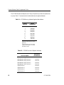
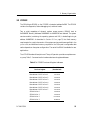
ICP2424 . . . . . . . . . . . . . . . . . . . . . . . . . . . . . . . . . . . . . . .
ICP2432 . . . . . . . . . . . . . . . . . . . . . . . . . . . . . . . . . . . . . . .
ICP6000 . . . . . . . . . . . . . . . . . . . . . . . . . . . . . . . . . . . . . . .
Download Procedures . . . . . . . . . . . . . . . . . . . .
4.1.1 Freeway Server Download Procedure . . . . . . . . .
4.1.1.1 Downloading Without the Debug Monitor . . .
4.1.1.2 Downloading With the Debug Monitor . . . . .
4.1.2 Embedded ICP Download Procedure . . . . . . . . .
4.1.3 ICP Buffer Size . . . . . . . . . . . . . . . . . . . . .
4.2 OS/Impact Configuration and Initialization . . . . . . . .
4.2.1 Configuration Table . . . . . . . . . . . . . . . . . .
4.2.2 Task Initialization Structures . . . . . . . . . . . . . .
4.2.3 Task Initialization Routine . . . . . . . . . . . . . . .
4.2.4 OS/Impact Initialization . . . . . . . . . . . . . . . .
4.3 Determining Configuration Parameters. . . . . . . . . . .
4.3.1 OS/Impact Memory Requirements . . . . . . . . . .
4.3.2 Configuration and System Performance. . . . . . . .
4.3.2.1 Number of Configured Task Control Structures
37
37
39
41
42
43
44
44
45
45
45
46
48
49
51
ICP Download, Configuration, and Initialization
4.1
4
.
.
.
.
.
.
.
.
.
.
.
.
.
.
51
53
54
57
.
.
.
.
.
.
.
.
.
.
.
.
.
.
.
.
.
.
.
.
.
.
.
.
.
.
.
.
.
.
.
.
.
.
.
.
.
.
.
.
.
.
.
.
.
.
.
.
.
.
.
.
.
.
.
.
.
.
.
.
.
.
.
.
.
.
.
.
.
.
.
.
.
.
.
.
.
.
.
.
.
.
.
.
.
.
.
.
.
.
.
.
.
.
.
.
.
.
.
.
.
.
.
.
.
.
.
.
.
.
.
.
.
.
.
.
.
.
.
.
.
.
.
.
.
.
.
.
.
.
.
.
.
.
.
.
.
.
.
.
.
.
.
.
.
.
.
.
.
.
.
.
.
.
.
.
.
.
.
.
.
.
.
.
.
57
57
59
63
64
64
65
72
72
74
74
75
75
77
78
DC 900-1338I
Contents
4.3.2.2
4.3.2.3
5
Number of Configured Priorities . . . . . . . . . . . . . . . . . . . . 78
Tick and Time Slice Lengths . . . . . . . . . . . . . . . . . . . . . . . 80
Debugging
5.1
5.2
5.3
5.4
6
PEEKER Debugging Tool .
PTBUG Debugging Tool. .
SingleStep Debugging Tool
System Panic Codes . . . .
81
.
.
.
.
.
.
.
.
.
.
.
.
.
.
.
.
.
.
.
.
.
.
.
.
.
.
.
.
.
.
.
.
.
.
.
.
.
.
.
.
.
.
.
.
.
.
.
.
.
.
.
.
.
.
.
.
.
.
.
.
.
.
.
.
.
.
.
.
.
.
.
.
.
.
.
.
.
.
.
.
.
.
.
.
.
.
.
.
.
.
.
.
.
.
.
.
.
.
.
.
.
.
.
.
.
.
.
.
.
.
.
.
ICP Software
ICP-resident Modules . . . . . . . . . . . . . .
6.1.1 System Initialization . . . . . . . . . . . .
6.1.2 Protocol Task . . . . . . . . . . . . . . . .
6.1.3 Utility Task (spshio) . . . . . . . . . . . .
6.1.3.1 Read Request Processing . . . . . . .
6.1.3.2 Write Request Processing . . . . . .
6.2 Control of Transmit and Receive Operations. .
6.2.1 Link Control Tables . . . . . . . . . . . .
6.2.2 SPS/ISR Interface for Transmit Messages .
6.2.3 SPS/ISR Interface for Received Messages .
6.3 Interrupt Service . . . . . . . . . . . . . . . . .
6.3.1 ISR Operation in HDLC/SDLC Mode . .
6.3.2 ISR Operation in Asynchronous Mode . .
6.3.3 ISR Operation in BSC Mode. . . . . . . .
.
.
.
.
.
.
.
.
.
.
.
.
.
.
.
.
.
.
.
.
.
.
.
.
.
.
.
.
.
.
.
.
.
.
.
.
.
.
.
.
.
.
.
.
.
.
.
.
.
.
.
.
.
.
.
.
.
.
.
.
.
.
.
.
.
.
.
.
.
.
.
.
.
.
.
.
.
.
.
.
.
.
.
.
.
.
.
.
.
.
.
.
.
.
.
.
.
.
.
.
.
.
.
.
.
.
.
.
.
.
.
.
.
.
.
.
.
.
.
.
.
.
.
.
.
.
.
.
.
.
.
.
.
.
.
.
.
.
.
.
.
.
.
.
.
.
.
.
.
.
.
.
.
.
.
.
.
.
.
.
.
.
.
.
.
.
.
.
.
.
.
.
.
.
.
.
.
.
.
.
.
.
.
.
.
.
.
.
.
.
.
.
.
.
.
.
.
.
.
.
.
.
.
.
.
.
.
.
.
.
.
.
.
.
.
.
.
.
.
.
.
.
.
.
.
.
.
.
.
.
.
.
.
.
.
.
.
.
Host/ICP Interface
7.1
7.2
ICP’s Host Interface Protocol . . . . . . . . .
Queue Elements . . . . . . . . . . . . . . . .
7.2.1 System Buffer Header . . . . . . . . . .
7.2.2 Queue Element Initialization . . . . . .
7.2.3 Node Declaration Queue Element . . .
7.2.3.1 System Buffer Header Initialization
7.2.3.2 Completion Status . . . . . . . . .
7.2.4 Host Request Queue Element . . . . . .
7.2.4.1 System Buffer Header Initialization
7.2.4.2 Host Request Header Initialization
DC 900-1338I
81
84
84
86
89
6.1
7
.
.
.
.
. 89
. 89
. 95
. 96
. 99
. 101
. 103
. 104
. 107
. 107
. 109
. 109
. 111
. 112
115
.
.
.
.
.
.
.
.
.
.
.
.
.
.
.
.
.
.
.
.
.
.
.
.
.
.
.
.
.
.
.
.
.
.
.
.
.
.
.
.
.
.
.
.
.
.
.
.
.
.
.
.
.
.
.
.
.
.
.
.
.
.
.
.
.
.
.
.
.
.
.
.
.
.
.
.
.
.
.
.
.
.
.
.
.
.
.
.
.
.
.
.
.
.
.
.
.
.
.
.
.
.
.
.
.
.
.
.
.
.
.
.
.
.
.
.
.
.
.
.
.
.
.
.
.
.
.
.
.
.
.
.
.
.
.
.
.
.
.
.
.
.
.
.
.
.
.
.
.
.
.
.
.
.
.
.
.
.
.
.
.
.
.
.
.
.
.
.
.
.
.
.
.
.
.
.
.
.
.
.
. 115
. 118
. 121
. 123
. 124
. 126
. 127
. 127
. 131
. 133
5
Protocol Software Toolkit Programmer Guide
7.2.4.3 Completion Status . . . . . . . . . . .
7.3 Reserved System Resources: XIO Interface . . . .
7.4 Executive Input/Output . . . . . . . . . . . . . .
7.4.1 Initialize Executive Input/Output (s_initxio)
7.4.2 Node Declaration (s_nodec) . . . . . . . . .
7.4.3 XIO Read/Write (s_xio) . . . . . . . . . . .
7.5 Diagnostics . . . . . . . . . . . . . . . . . . . . .
8
.
.
.
.
.
.
.
.
.
.
.
.
.
.
.
.
.
.
.
.
.
.
.
.
.
.
.
.
.
.
.
.
.
.
.
.
.
.
.
.
.
.
.
.
.
.
.
.
.
.
.
.
.
.
.
.
.
.
.
.
.
.
.
.
.
.
.
.
.
.
.
.
.
.
.
.
.
.
.
.
.
.
.
.
.
.
.
.
.
.
.
.
.
.
.
.
.
.
.
.
.
.
.
.
.
Client Applications — DLI Overview
Summary of DLI Concepts. . . . . . . . . . . . . . . . . . . . . . . . . . .
8.1.1 Configuration in the Freeway Server or Embedded ICP Environment
8.1.1.1 DLI Configuration for Raw Operation. . . . . . . . . . . . . . .
8.1.1.2 DLI and TSI Configuration Process . . . . . . . . . . . . . . . .
8.1.2 Blocking versus Non-blocking I/O. . . . . . . . . . . . . . . . . . . .
8.1.3 Buffer Management. . . . . . . . . . . . . . . . . . . . . . . . . . . .
8.2 Example Call Sequences . . . . . . . . . . . . . . . . . . . . . . . . . . . .
8.3 Overview of DLI Functions . . . . . . . . . . . . . . . . . . . . . . . . . .
9
.
.
.
.
.
.
.
.
.
.
.
.
.
.
.
.
Client Applications — Commands and Responses
9.1
9.2
Client and ICP Interface Data Structures . . . . . . . . . . .
Client and ICP Communication . . . . . . . . . . . . . . . .
9.2.1 Sequence of Client Events to Communicate to the ICP.
9.2.2 Initiating a Session with the ICP (dlOpen) . . . . . . .
9.2.3 Initiating a Session with an ICP Link (Attach) . . . . .
9.2.4 Terminating a Session with an ICP Link (Detach) . . .
9.2.5 Activating an ICP Link (Bind) . . . . . . . . . . . . . .
9.2.5.1 X21bis Line Status Reports (Optional) . . . . . .
9.2.6 Deactivating an ICP Link (Unbind) . . . . . . . . . . .
9.2.7 Writing to an ICP Link . . . . . . . . . . . . . . . . . .
9.2.7.1 Configuring the ICP Link. . . . . . . . . . . . . .
9.2.7.2 Requesting Link Statistics From the ICP . . . . . .
9.2.7.3 Writing Data to an ICP Link . . . . . . . . . . . .
9.2.8 Reading from the ICP Link. . . . . . . . . . . . . . . .
9.2.8.1 Reading Normal Data. . . . . . . . . . . . . . . .
9.3 Additional Command Types Supported by the SPS . . . . .
9.3.1 Internal Termination Message . . . . . . . . . . . . . .
134
135
135
136
136
137
137
141
8.1
6
.
.
.
.
.
.
.
142
142
143
147
151
152
153
155
157
.
.
.
.
.
.
.
.
.
.
.
.
.
.
.
.
.
.
.
.
.
.
.
.
.
.
.
.
.
.
.
.
.
.
.
.
.
.
.
.
.
.
.
.
.
.
.
.
.
.
.
.
.
.
.
.
.
.
.
.
.
.
.
.
.
.
.
.
.
.
.
.
.
.
.
.
.
.
.
.
.
.
.
.
.
.
.
.
.
.
.
.
.
.
.
.
.
.
.
.
.
.
.
.
.
.
.
.
.
.
.
.
.
.
.
.
.
.
.
.
.
.
.
.
.
.
.
.
.
.
.
.
.
.
.
.
.
.
.
.
.
.
.
.
.
.
.
.
.
.
.
.
.
.
.
.
.
.
.
.
.
.
.
.
.
.
.
.
.
.
157
161
162
163
164
167
169
171
172
174
175
179
182
185
185
187
187
DC 900-1338I
Contents
9.3.2
9.3.3
Internal Test Message . . . . . . . . . . . . . . . . . . . . . . . . . . . . . 188
Internal Ping . . . . . . . . . . . . . . . . . . . . . . . . . . . . . . . . . . 188
A
Application Notes
189
B
Data Rate Time Constants for SCC/IUSC Programming
191
C
Error Codes
195
C.1 DLI Error Codes . . . . . . . . . . . . . . . . . . . . . . . . . . . . . . . . . . . 195
C.2 ICP Global Error Codes . . . . . . . . . . . . . . . . . . . . . . . . . . . . . . . 195
C.3 ICP Error Status Codes . . . . . . . . . . . . . . . . . . . . . . . . . . . . . . . 195
Index
DC 900-1338I
197
7
Protocol Software Toolkit Programmer Guide
8
DC 900-1338I
List of Figures
Figure 1–1: Freeway Configuration. . . . . . . . . . . . . . . . . . . . . . . . . . . . . 22
Figure 1–2: Embedded ICP Configuration. . . . . . . . . . . . . . . . . . . . . . . . . 23
Figure 1–3: A Typical Freeway Server Environment . . . . . . . . . . . . . . . . . . . . 25
Figure 1–4: ICP PROM and Toolkit Software Components — Freeway Server . . . . . 29
Figure 1–5: ICP PROM and Toolkit Software Components — Embedded ICP . . . . . 30
Figure 2–1: Assembly Language Shell . . . . . . . . . . . . . . . . . . . . . . . . . . . 41
Figure 2–2: Test Mode Register, ICP2424 . . . . . . . . . . . . . . . . . . . . . . . . . 45
Figure 2–3: Test Mode Register, ICP2432 . . . . . . . . . . . . . . . . . . . . . . . . . 45
Figure 4–1: Protocol Toolkit Download Script File (spsload) . . . . . . . . . . . . . . . 60
Figure 4–2: ICP2424 Memory Layout with Application Only . . . . . . . . . . . . . . 66
Figure 4–3: ICP2424 Memory Layout with Application and SDS Debug Monitor . . . 67
Figure 4–4: ICP2432 Memory Layout with Application Only . . . . . . . . . . . . . . 68
Figure 4–5: ICP2432 Memory Layout with Application and SDS Debug Monitor . . . 69
Figure 4–6: ICP6000 Memory Layout with Application Only . . . . . . . . . . . . . . 70
Figure 4–7: ICP6000 Memory Layout with Application and SDS Debug Monitor . . . 71
Figure 4–8: Sample Configuration Table . . . . . . . . . . . . . . . . . . . . . . . . . . 72
Figure 4–9: Sample Configuration Table with Task Initialization Structures. . . . . . . 73
Figure 4–10: Sample Task Initialization Routine . . . . . . . . . . . . . . . . . . . . . . 74
Figure 6–1: Sample ICP2424 Protocol Software Memory Layout. . . . . . . . . . . . . 90
Figure 6–2: Sample ICP2432 Protocol Software Memory Layout. . . . . . . . . . . . . 91
Figure 6–3: Sample ICP6000 Protocol Software Memory Layout. . . . . . . . . . . . . 92
Figure 6–4: Block Diagram of the Sample Protocol Software — Freeway Server . . . . 93
Figure 6–5: Block Diagram of the Sample Protocol Software — Embedded ICP . . . . 94
Figure 6–6: Sample Protocol Software Message Format . . . . . . . . . . . . . . . . . . 98
Figure 6–7: ICP Read Request (Transmit Data) Processing . . . . . . . . . . . . . . . . 100
DC 900-1338I
9
Protocol Software Toolkit Programmer Guide
Figure 6–8: ICP Write Request (Receive Data) Processing . . . . . . . . . . . . . . . . 102
Figure 6–9: Sample Link-to-Board Queue . . . . . . . . . . . . . . . . . . . . . . . . 108
Figure 7–1: Sample Singly-linked Queue with Three Elements . . . . . . . . . . . . . 119
Figure 7–2: Sample Doubly-linked Queue with Three Elements . . . . . . . . . . . . 120
Figure 7–3: Node Declaration Queue Element . . . . . . . . . . . . . . . . . . . . . . 125
Figure 7–4: Host Request Queue Element with Data Area. . . . . . . . . . . . . . . . 128
Figure 8–1: DLI Configuration File for Two Links (Freeway Server) . . . . . . . . . . 145
Figure 8–2: DLI Configuration File for Two Embedded ICP Links (DLITE Interface) . 146
Figure 8–3: DLI and TSI Configuration Process . . . . . . . . . . . . . . . . . . . . . 150
Figure 9–1: “C” Definition of DLI Optional Arguments Structure . . . . . . . . . . . 158
Figure 9–2: “C” Definition of api_msg Data Structure . . . . . . . . . . . . . . . . . 159
Figure 9–3: “C” Definition of icp_hdr and prot_hdr Data Structures. . . . . . . . . . 159
Figure 9–4: Attach Command Format . . . . . . . . . . . . . . . . . . . . . . . . . . 164
Figure 9–5: Attach Response Format . . . . . . . . . . . . . . . . . . . . . . . . . . . 166
Figure 9–6: Detach Command Format . . . . . . . . . . . . . . . . . . . . . . . . . . 167
Figure 9–7: Detach Response Format . . . . . . . . . . . . . . . . . . . . . . . . . . . 168
Figure 9–8: Bind Command Format . . . . . . . . . . . . . . . . . . . . . . . . . . . 169
Figure 9–9: Bind Response Format . . . . . . . . . . . . . . . . . . . . . . . . . . . . 170
Figure 9–10: Unbind Command Format. . . . . . . . . . . . . . . . . . . . . . . . . . 172
Figure 9–11: Unbind Response Format . . . . . . . . . . . . . . . . . . . . . . . . . . 173
Figure 9–12: Link Configuration “C” Structure . . . . . . . . . . . . . . . . . . . . . . 175
Figure 9–13: Configure Link Command Format . . . . . . . . . . . . . . . . . . . . . 177
Figure 9–14: Configure Link Response Format . . . . . . . . . . . . . . . . . . . . . . 178
Figure 9–15: Request Link Statistics Command Format . . . . . . . . . . . . . . . . . 179
Figure 9–16: Statistics Report Response Format . . . . . . . . . . . . . . . . . . . . . . 181
Figure 9–17: Statistics Report “C” Structure . . . . . . . . . . . . . . . . . . . . . . . . 181
Figure 9–18: Send Data Command Format . . . . . . . . . . . . . . . . . . . . . . . . 182
Figure 9–19: Data Acknowledgment Response . . . . . . . . . . . . . . . . . . . . . . 184
Figure 9–20: Receive Data from ICP Response . . . . . . . . . . . . . . . . . . . . . . 186
10
DC 900-1338I
List of Tables
Table 2–1:
Vectors Reserved for System Software . . . . . . . . . . . . . . . . . . . . . 40
Table 2–2:
ICP Interrupt Priority Assignments . . . . . . . . . . . . . . . . . . . . . . 42
Table 2–3:
LED Control Information . . . . . . . . . . . . . . . . . . . . . . . . . . . 43
Table 2–4:
SP502 or SP504 Electrical Interface Values . . . . . . . . . . . . . . . . . . 44
Table 2–5:
Setup for MFP Initialization . . . . . . . . . . . . . . . . . . . . . . . . . . 47
Table 2–7:
SCC Access Registers . . . . . . . . . . . . . . . . . . . . . . . . . . . . . . 48
Table 2–6:
Vector Numbers for SCC Interrupts . . . . . . . . . . . . . . . . . . . . . . 48
Table 3–1:
ICP2424 Memory Address Registers Base Address . . . . . . . . . . . . . . 52
Table 3–2:
ICP2424 Device and Register Addresses . . . . . . . . . . . . . . . . . . . . 52
Table 3–3:
ICP2432 Device and Register Addresses . . . . . . . . . . . . . . . . . . . . 53
Table 3–4:
ICP6000 Device and Register Addresses . . . . . . . . . . . . . . . . . . . . 55
Table 3–5:
ICP6000 VME Slave Address Registers Base Address . . . . . . . . . . . . . 56
Table 4–1:
System Data Requirements . . . . . . . . . . . . . . . . . . . . . . . . . . . 76
Table 4–2:
Sample Calculation of System Data Requirements . . . . . . . . . . . . . . 76
Table 6–1:
Summary of Communication Modes . . . . . . . . . . . . . . . . . . . . . 109
Table 8–1:
Include Files. . . . . . . . . . . . . . . . . . . . . . . . . . . . . . . . . . . 142
Table 8–2:
Configuration File Names . . . . . . . . . . . . . . . . . . . . . . . . . . . 147
Table 8–3:
DLI Call Sequence for Blocking I/O . . . . . . . . . . . . . . . . . . . . . . 153
Table 8–4:
DLI Call Sequence for Non-blocking I/O . . . . . . . . . . . . . . . . . . . 154
Table 8–5:
DLI Functions: Syntax and Parameters (Listed in Typical Call Order). . . . 156
Table 9–1:
Comparison of DLI_OPT_ARGS and ICP_HDR/PROT_HDR Fields . . . . 160
Table 9–2:
Command/Response Code Summary . . . . . . . . . . . . . . . . . . . . . 161
Table B–1:
SCC Time Constants for 1X Clock Rate for ICP6000 . . . . . . . . . . . . . 192
Table B–2:
SCC Time Constants for 16X Clock Rate for ICP6000 . . . . . . . . . . . . 192
Table B–3:
IUSC Time Constants for 1X Clock Rate for ICP2424 and ICP2432. . . . . 193
DC 900-1338I
11
Protocol Software Toolkit Programmer Guide
Table B–4:
IUSC Time Constants for 16X Clock Rate for ICP2424 and ICP2432 . . . 193
Table C–1: ICP Error Status Codes used by the ICP . . . . . . . . . . . . . . . . . . . 196
12
DC 900-1338I
Preface
Purpose of Document
This document describes the protocol software toolkit for the Freeway server and
embedded intelligent communications processor (ICP) environments, and discusses
the issues involved in developing software that executes in either of these environments.
It also provides information on client application programs and the host/ICP interface.
Note
The Protocol Toolkit is designed to be used either with a Freeway
server or an embedded ICP using DLITE. For the embedded ICP,
also refer to the user guide for your ICP and operating system (for
example, the ICP2432 User Guide for Windows NT).
Intended Audience
This document should be read by programmers who are developing code to be downloaded to the ICP2424, ICP2432, or ICP6000. You should be familiar with your client
system’s operating system and with program development in a real-time environment.
Familiarity with the C programming language and Motorola 68xxx assembly language
is helpful.
Required Equipment
You must have the following equipment to use the protocol software toolkit to develop
and test communications applications:
DC 900-1338I
13
Protocol Software Toolkit Programmer Guide
•
•
a client computer that runs the following:
•
TCP/IP (for a Freeway server)
•
Freeway data link interface (DLI) or embedded DLITE interface
An ICP2424, ICP2432, or ICP6000 installed in the Freeway server’s backplane or
embedded in your client computer system
•
A console cable and an ASCII terminal or terminal emulator (running at 9600
b/s) for access to the ICP console port
•
A programmer’s module for the ICP2432 or ICP6000
•
A set of software development tools for the Motorola 68xxx processor
•
If you plan to use the sample protocol software (SPS) test program as a basis for
your client application code, you will need a C compiler for your client system
Organization of Document
Chapter 1 is an overview of the Freeway server and embedded products and the protocol software toolkit.
Chapter 2 describes the issues involved in ICP software development, including software-development tools, the various interfaces, and how to program the hardware
devices.
Chapter 3 describes local memory address allocation on the ICPs.
Chapter 4 describes system download, configuration, and initialization.
Chapter 5 describes the ICP debugging tools and techniques.
Chapter 6 describes the ICP software.
14
DC 900-1338I
Preface
Chapter 7 gives an overview of the interface between the ICP’s host processor and an
ICP. It also describes the interface between the ICP’s driver, XIO, and OS/Impact application tasks.
Chapter 8 gives an overview of DLI concepts relating to client applications.
Chapter 9 describes the messages exchanged between the client and the ICP.
Techpubs:
Don’t delete
the “Other
Helpful
Documents”
(separate
table at end of
References).
Also set “space
below” on first
table = 0 pt.
Appendix A clarifies some points made in the technical manuals and describes some
peculiarities of the devices and the ICP6000 hardware.
Appendix B provides some commonly used data rate time constants for SCC programming on the ICP6000.
Appendix C describes error codes.
11/16/99
Leslie: Add
1567 to the
“Specials”
table.
Protogate References
The following general product documentation list is to familiarize you with the available Protogate Freeway and embedded ICP products. The applicable product-specific
reference documents are mentioned throughout each document (also refer to the
“readme” file shipped with each product). Most documents are available on-line at Protogate’s web site, www.protogate.com.
General Product Overviews
•
•
•
•
Freeway 1100 Technical Overview
25-000-0419
Freeway 2000/4000/8800 Technical Overview
25-000-0374
ICP2432 Technical Overview
25-000-0420
ICP6000X Technical Overview
25-000-0522
Hardware Support
•
•
•
Freeway 1100/1150 Hardware Installation Guide
DC-900-1370
Freeway 1200/1300 Hardware Installation Guide
DC-900-1537
Freeway 2000/4000 Hardware Installation Guide
DC-900-1331
DC 900-1338I
15
Protocol Software Toolkit Programmer Guide
•
•
•
Freeway 8800 Hardware Installation Guide
DC-900-1553
Freeway ICP6000R/ICP6000X Hardware Description
DC-900-1020
ICP6000(X)/ICP9000(X) Hardware Description and Theory of
Operation
DC-900-0408
•
•
•
•
ICP2424 Hardware Description and Theory of Operation
DC-900-1328
ICP2432 Hardware Description and Theory of Operation
DC-900-1501
ICP2432 Electrical Interfaces (Addendum to DC-900-1501)
DC-900-1566
ICP2432 Hardware Installation Guide
DC-900-1502
Freeway Software Installation and Configuration Support
•
•
•
•
Freeway Message Switch User Guide
DC-900-1588
Freeway Release Addendum: Client Platforms
DC-900-1555
Freeway User Guide
DC-900-1333
Freeway Loopback Test Procedures
DC-900-1533
Embedded ICP Software Installation and Programming Support
•
•
•
•
•
•
ICP2432 User Guide for Digital UNIX
DC-900-1513
ICP2432 User Guide for OpenVMS Alpha
DC-900-1511
ICP2432 User Guide for OpenVMS Alpha (DLITE Interface)
DC-900-1516
ICP2432 User Guide for Solaris STREAMS
DC-900-1512
ICP2432 User Guide for Windows NT
DC-900-1510
ICP2432 User Guide for Windows NT (DLITE Interface)
DC-900-1514
Application Program Interface (API) Programming Support
•
•
•
Freeway Data Link Interface Reference Guide
DC-900-1385
Freeway Transport Subsystem Interface Reference Guide
DC-900-1386
QIO/SQIO API Reference Guide
DC-900-1355
Socket Interface Programming Support
•
Freeway Client-Server Interface Control Document
DC-900-1303
Toolkit Programming Support
•
16
Freeway Server-Resident Application and Server Toolkit
Programmer Guide
DC-900-1325
DC 900-1338I
Preface
•
•
OS/Impact Programmer Guide
DC-900-1030
Protocol Software Toolkit Programmer Guide
DC-900-1338
Protocol Support
•
•
•
•
•
•
•
•
•
•
•
•
•
•
•
ADCCP NRM Programmer Guide
DC-900-1317
Asynchronous Wire Service (AWS) Programmer Guide
DC-900-1324
AUTODIN Programmer Guide
DC-908-1558
Bit-Stream Protocol Programmer Guide
DC-900-1574
BSC Programmer Guide
DC-900-1340
BSCDEMO User Guide
DC-900-1349
BSCTRAN Programmer Guide
DC-900-1406
DDCMP Programmer Guide
DC-900-1343
FMP Programmer Guide
DC-900-1339
Military/Government Protocols Programmer Guide
DC-900-1602
N/SP-STD-1200B Programmer Guide
DC-908-1359
SIO STD-1300 Programmer Guide
DC-908-1559
X.25 Call Service API Guide
DC-900-1392
X.25/HDLC Configuration Guide
DC-900-1345
X.25 Low-Level Interface
DC-900-1307
Other Documents (Available from Protogate)
•
•
•
•
Protogate Order #
MC68000 Family Reference Manual (Motorola)
DC 900-0698
MC68901 Multi-function Peripheral (Motorola)
DC MC68901/D
PTBUG Debug and Utility Program Reference Manual (PTI)
DC 900-0424
Serial Communications Controller User’s Manual (Zilog)
DC 00-2057-05
Other Documents (Available from Vendor)
Vendor
•
MC68340 Integrated Processor with DMA User’s Manual
Motorola,
MC 68340UM/AD
•
MC68349 High Performance Integrated Processor User’s Manual
Motorola,
MC 68349UM/AD
•
User’s Manual, PT-VME340, High Speed Synchronous Communi- Performance Technologies, Inc. (PTI),
cations Controller
126A0137
DC 900-1338I
17
Protocol Software Toolkit Programmer Guide
•
Z16C32 IUSC Integrated Universal Serial Controller Technical Zilog,
DC8292-01
Manual
Other Documents (Development Tools and Environment)
Vendor
•
•
•
CrossCodeC for the 68000 Microprocessor Family
Wind River
M68000 Family Resident Structured Assembler Reference Manual
Motorola
•
SingleStep Debugger for the 68000 Microprocessor Family
PTBUG Debug and Utility Program, Model PT-VME800-10393, PTI,
811A017910
Reference Manual for VME 340
Wind River
Document Conventions
This document follows the most significant byte first (MSB) and most significant word
first (MSW) conventions for bit-numbering and byte-ordering. In all packet transfers
between the client applications and the ICPs, the ordering of the byte stream is preserved.
The term “Freeway” refers to any of the Freeway server models (for example, Freeway
500/3100/3200/3400 PCI-bus servers, Freeway 1000 ISA-bus servers, or Freeway
2000/4000/8800 VME-bus servers). References to “Freeway” also may apply to an
embedded ICP product using DLITE (for example, the embedded ICP2432 using
DLITE on a Windows NT system).
Physical “ports” on the ICPs are logically referred to as “links.” However, since port and
link numbers are usually identical (that is, port 0 is the same as link 0), this document
uses the term “link.”
Program code samples are written in the “C” programming language.
Revision History
The revision history of the Protocol Software Toolkit Programmer Guide, Protogate document DC 900-1338I, is recorded below:
18
DC 900-1338I
Preface
Revision
Release Date
DC 900-1338A November 4, 1994
Description
Original release
DC 900-1338B November 22, 1994 Update file names for Release 2.1
Add “Loopback Test Program” appendix
DC 900-1338C July 1995
Update file names
Add ICP2424 information
DC 900-1338D February 1996
Minor modifications throughout
Add ICP6030 information
Add new dlControl function to Table 8–5 on page 156
Add Windows NT to Loopback Test Program appendix
Delete HIO task information
DC 900-1338E November 1997
Add embedded ICP product information
Add ICP2432 information
Document changes in directory structure
DC 900-1338F December 1998
Minor modifications throughout.
Chapter 8 is now a programming overview, and Chapter 9
contains all the command and response formats.
Add command/response summary (Table 9–2 on page 161)
Add electrical interface values (Section 9.2.7.1 on page 175)
DC 900-1338G April 1999
Minor modifications throughout for embedded ICP users
Update electrical interface information (Table 2–4 on page 44)
Remove appendix for the loopback test. This information is
included in the Freeway Loopback Test Procedures document
(for a Freeway server) or the user guide for your embedded
ICP and operating system (for example, the ICP2432 User
Guide for Windows NT).
DC 900-1338H December 1999
Protocol Toolkit no longer supports the ICP6030
Modify Section 4.1.1.1 on page 59
Add Section 4.1.3 on page 64, “ICP Buffer Size”
Add Section 9.2.5.1 on page 171, “X21bis Line Status Reports”
Modify Section 9.2.7.1 on page 175 & Section 9.2.7.3 on page 182
Add new error codes to Table C–1 on page 196
DC 900-1338I January 2002
Update Document for Protogate, Inc.
Add new Freeway model numbers
Customer Support
If you are having trouble with any Protogate product, call us at (858) 451-0865 Monday
through Friday between 8 a.m. and 5 p.m. Pacific time.
You can also fax your questions to us at (877) 473-0190 any time. Please include a cover
sheet addressed to “Customer Service.”
DC 900-1338I
19
Protocol Software Toolkit Programmer Guide
We are always interested in suggestions for improving our products. You can use the
report form in the back of this manual to send us your recommendations.
20
DC 900-1338I
Chapter
1
Introduction
1.1 Product Overview
Most recent
modification
date:
6/1/99 Ginni:
Added
1200/1300 to
FW list
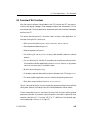
Protogate provides a variety of wide-area network (WAN) connectivity solutions for
real-time financial, defense, telecommunications, and process-control applications.
Protogate’s Freeway server offers flexibility and ease of programming using a variety of
LAN-based server hardware platforms. Now a consistent and compatible embedded
intelligent communications processor (ICP) product offers the same functionality as
the Freeway server, allowing individual client computers to connect directly to the
WAN.
Both Freeway and the embedded ICP use the same data link interface (DLI for Freeway,
DLITE for embedded ICP). Therefore, migration between the two environments simply requires linking your client application with the proper library. The DLI library is
supported on various client operating systems (for example, UNIX, VMS, and Windows NT). The DLITE library requires a compatible ICP device driver to operate and is
currently available on Windows NT/2000 and VMS (AXP systems only).
Protogate protocols that run on the ICPs are independent of the client operating system
and the hardware platform (Freeway or embedded ICP).
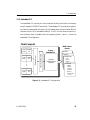
1.1.1 Freeway Server
Protogate’s Freeway communications servers enable client applications on a local-area
network (LAN) to access specialized WANs through the DLI. The Freeway server can be
any of several models that use the ICP2432, ICP2424, or ICP6000 products. The
Freeway server is user programmable and communicates in real time. It provides mulDC 900-1338I
21
Protocol Software Toolkit Programmer Guide
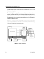
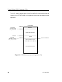
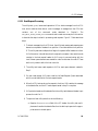
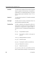
tiple data links and a variety of network services to LAN-based clients. Figure 1–1 shows
the Freeway configuration.
To maintain high data throughput, Freeway uses a multi-processor architecture to support the LAN and WAN services. The LAN interface is managed by a single-board computer, called the server processor. It uses commercially available operating systems such
as VxWorks or BSD Unix to provide a full-featured base for the LAN interface and layered services needed by Freeway.
Freeway can be configured with multiple WAN interface processor boards, each of
which is a Protogate ICP. Each ICP runs the communication protocol software using
OS/Impact, Protogate’s real-time operating system.
AAAAAAAA
AAAAAAAA
AAAAAAAA
AAAAAAAA
AAAAAAAA
AAAAAAAA
AAAAAAAA
AAAAAAAA
AAAAAAAA
Industry Standard Bus
AA
AA
AA
AA
AA
AA
AA
AA
Server Processor
WAN
Interface
Processors
WAN Protocol
Options
SCADA
ICP
Defense
Commercial
X.25
Bisync
HDLC . . .
● ● ●
Freeway
Financial
SWIFT
CHIPS
Telerate
Telekurs
Reuters
40+ Market
Feeds . . .
ICP
Ethernet LAN
Freeway
API
Application
Application
Application
Client 1
Client 2
Client n
●
●
●
3413
Freeway
API
Freeway
API
Figure 1–1: Freeway Configuration
22
DC 900-1338I
1: Introduction
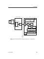
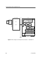
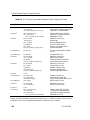
1.1.2 Embedded ICP
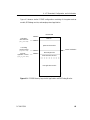
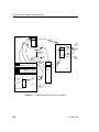
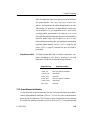
The embedded ICP connects your client computer directly to the WAN (for example,
using Protogate’s ICP2432 PCIbus board). The embedded ICP provides client applications with the same WAN connectivity as the Freeway server, using the same data link
interface (via the DLITE embedded interface). The ICP runs the communication protocol software using Protogate’s real-time operating system. Figure 1–2 shows the
embedded ICP configuration.
Client Computer
AAA
AAAAA
AAA
AA
AAA
AA
AAAAA
AAA
AA
AAAAA
AAA
AA
AAAAA
AAA
AA
AAA
Industry Standard Bus
●
●
●
Client Freeway
Appl 1
API
Simpact Driver
Client Freeway
Appl 1
API
WAN Protocol
Options
Freeway
Embedded ICP
SCADA
Defense
Commercial
X.25
Bisync
HDLC . . .
Simpact
WAN Protocol
Software
3414
Client Freeway
Appl 1
API
Financial
SWIFT
CHIPS
Telerate
Telekurs
Reuters
40+ Market
Feeds . . .
Figure 1–2: Embedded ICP Configuration
DC 900-1338I
23
Protocol Software Toolkit Programmer Guide
Summary of product features:
•
Provision of WAN connectivity either through a LAN-based Freeway server or
directly using an embedded ICP
•
Elimination of difficult LAN and WAN programming and systems integration by
providing a powerful and consistent data link interface
•
Variety of off-the-shelf communication protocols available from Protogate which
are independent of the client operating system and hardware platform
•
Support for multiple WAN communication protocols simultaneously
•
Support for multiple ICPs (two, four, eight, or sixteen communication lines per
ICP)
•
Wide selection of electrical interfaces including EIA-232, EIA-449, EIA-530, and
V.35
•
Creation of customized server-resident and ICP-resident software, using Protogate’s software development toolkits
•
Freeway server standard support for Ethernet and Fast Ethernet LANs running
the transmission control protocol/internet protocol (TCP/IP)
•
Freeway server standard support for FDDI LANs running the transmission control protocol/ internet protocol (TCP/IP)
•
Freeway server management and performance monitoring with the simple network management protocol (SNMP), as well as interactive menus available
through a local console, telnet, or rlogin
24
DC 900-1338I
1: Introduction
1.2 Freeway Client-Server Environment
The Freeway server acts as a gateway that connects a client on a local-area network to a
wide-area network. Through Freeway, a client application can exchange data with a
remote data link application. Your client application must interact with the Freeway
server and its resident ICPs before exchanging data with the remote data link application.
One of the major Freeway server components is the message multiplexor (MsgMux)
that manages the data traffic between the LAN and the WAN environments. The client
application typically interacts with the Freeway MsgMux through a TCP/IP BSD-style
socket interface (or a shared-memory interface if it is a server-resident application
(SRA)). The ICPs interact with the MsgMux through the DMA and/or shared-memory
interface of the industry-standard bus to exchange WAN data. From the client application’s point of view, these complexities are handled through a simple and consistent
data link interface (DLI), which provides dlOpen, dlWrite, dlRead, and dlClose functions.
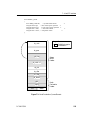
Figure 1–3 shows a typical Freeway connected to a locally attached client by a TCP/IP
network across an Ethernet LAN interface. Running a client application in the Freeway
client-server environment requires the basic steps described in Section 1.2.1 and
Section 1.4.
Client
Application DLI TSI
TCP/IP
TCP/IP
Socket Interface
client1
192.52.107.99
Freeway
SRA
Msg
TSI Mux
ICP0
ICP1
WAN
Protocols
ICP2
ICP3
3125
Shared Memory
Interface
Ethernet
Industry
Standard Bus
Client
freeway2
192.52.107.100
Figure 1–3: A Typical Freeway Server Environment
DC 900-1338I
25
Protocol Software Toolkit Programmer Guide
1.2.1 Establishing Freeway Server Internet Addresses
The Freeway server must be addressable in order for a client application to communicate with it. In the Figure 1–3 example, the TCP/IP Freeway server name is freeway2,
and its unique Internet address is 192.52.107.100. The client machine where the client
application resides is client1, and its unique Internet address is 192.52.107.99. Refer to
the Freeway Server User’s Guide to initially set up your Freeway and download the operating system, server, and protocol software.
1.3 Embedded ICP Environment
Refer to the user guide for your embedded ICP and operating system (for example, the
Freeway Embedded ICP2432 User’s Guide for Windows NT) for software installation and
setup instructions. The user guide also gives additional information regarding the data
link interface (DLI) and embedded programming interface descriptions for your specific embedded environment. Refer back to Figure 1–2 on page 23 for a diagram of the
embedded ICP environment. Running a client application in the embedded ICP environment requires the basic steps described in Section 1.4
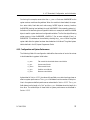
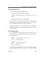
1.4 Client Operations
1.4.1 Defining the DLI and TSI Configuration
In order for your client application to communicate with the ICP’s protocol software,
you must define the DLI sessions and the transport subsystem interface (TSI) connections. You have the option of also defining the protocol-specific ICP link parameters.
To accomplish this, you first define the configuration parameters in DLI and TSI ASCII
configuration files, and then you run two preprocessor programs, dlicfg and tsicfg, to
create binary configuration files. The dlInit function uses the binary configuration files
to initialize the DLI environment.
26
DC 900-1338I
1: Introduction
1.4.2 Opening a Session
After the DLI and TSI configurations are properly defined, your client application uses
the dlOpen function to establish a DLI session with an ICP link. As part of the session
establishment process, the DLI establishes a TSI connection with the Freeway MsgMux
through the TCP/IP BSD-style socket interface for the Freeway server, or directly to the
ICP driver for the embedded ICP environment.
1.4.3 Exchanging Data with the Remote Application
After the link is enabled, the client application can exchange data with the remote application using the dlWrite and dlRead functions.
1.4.4 Closing a Session
When your application finishes exchanging data with the remote application, it calls the
dlClose function to disable the ICP link, close the session with the ICP, and disconnect
from the Freeway server or the embedded ICP driver.
DC 900-1338I
27
Protocol Software Toolkit Programmer Guide
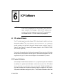
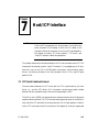
1.5 Protocol Toolkit Overview
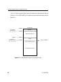
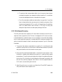
The protocol software toolkit helps you develop serial protocol applications for execution on Protogate’s intelligent communications processors. Many of the software modules required to build a complete system are provided with the toolkit or reside in the
ICP’s PROM, including download facilities, operating system, and the PTBUG
(ICP6000) or Peeker (ICP2424 and ICP2432) debugging tool. The toolkit also includes
a debug monitor program for use with Software Development Systems’ SingleStep
debugger. (The SingleStep debugger must be purchased directly from Software Development Systems.) All you have to provide is your application code, which you can build
using the toolkit’s sample protocol software as a model. Chapter 2, Chapter 4, and
Chapter 5 give more information on software development, configuration, and debugging.
The toolkit includes software, provided on the distribution media, and complete documentation (see the document “References” section in the Preface). Some of the toolkit’s
software components, such as the SingleStep monitor, are provided only in executable
object format. All other components are provided in both source and executable form
so that they can be modified, used as coding examples, or linked with user applications.
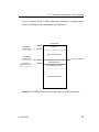
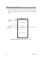
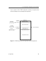
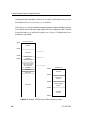
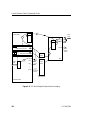
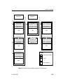
Figure 1–4 shows a block diagram of the ICP’s PROM and the toolkit’s software components for the Freeway server. Figure 1–5 shows the same information for the embedded ICP products.
28
DC 900-1338I
1: Introduction
Server Processor
ICP
PROM
Boot
Loader
Application
SPS Test
Program
Program
Interface
Serverresident
Applications
Server/ICP
Driver
XIO
Low-level
Debugger
Utility
Task
Power-up/
Reset
Diagnostics
Protocol
Task
Transmit
Pre-processor
VxWorks
Receive
Post-processor
Device-specific Procedures
Start Transmit Initialization Start Receive
Device-specific ISRs
Receive
...
3415
SDS
Debug
Monitor
Transmit Specific Conditions
Serial Ports
ISAbus,
PCIbus, or
VMEbus
Figure 1–4: ICP PROM and Toolkit Software Components — Freeway Server
DC 900-1338I
Scaled 76%
29
Protocol Software Toolkit Programmer Guide
Host Processor
ICP
PROM
SPS Test
Program
Application
Program
Interface
Boot
Loader
Low-level
Debugger
Power-up/
Reset
Diagnostics
Host OS
XIO
ICP Driver
Utility
Task
Protocol
Task
Transmit
Pre-processor
Receive
Post-processor
Device-specific Procedures
Start Transmit Initialization Start Receive
Device-specific ISRs
Receive
3416
SDS
Debug
Monitor
Transmit Specific Conditions
...
Serial Ports
ISAbus,
PCIbus, or
VMEbus
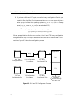
Figure 1–5: ICP PROM and Toolkit Software Components — Embedded ICP
Scaled 76%
30
DC 900-1338I
1: Introduction
1.5.1 Toolkit Software Components
The toolkit loopback test program (spsalp.c) is provided in source form and, when compiled, executes in the client application program’s system environment. For the test
procedures, see the “Protocol Toolkit Test Procedure” section in the Freeway Loopback
Test Procedures document or the appropriate embedded ICP user guide.
The following programs execute on the ICP:
•
System-services module containing the OS/Impact operating system and the XIO
ICP-side driver (sources provided)
•
Sample protocol software (source provided)
•
Sample host interface I/O utility (source provided)
•
Debug monitor; must be used with the Software Development Systems’
SingleStep monitor package (executable code only)
The following source files aid in ICP software development:
•
Subroutine library for C interface to OS/Impact
•
Macro library for assembly interface to OS/Impact
•
Header files with OS/Impact and XIO definitions and equates
•
Make files for supplied source files
•
*.spc files for linking and address resolution of the executable images
DC 900-1338I
31
Protocol Software Toolkit Programmer Guide
32
DC 900-1338I
Chapter
2
Software Development
for the ICP
This chapter describes the issues involved in developing software for the Protogate
ICPs, including software-development tools, the client application program interfaces,
and the hardware devices. The application program interface between the client and
ICP protocol tasks are described in the Freeway Transport Subsystem Interface Reference
Guide and Freeway Data Link Interface Reference Guide. The interface between the ICP
and the server (for Freeway server systems) or remote (for embedded ICP systems) is
described in Chapter 7 of this manual.
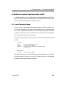
2.1 Board-level Protocol-executable Modules
An ICP board-level protocol-executable module is an absolute image file containing
Motorola 68xxx code and data developed on a CrossCodeC development system and
subsequently downloaded to the ICP. Any division of code and data among modules is
entirely arbitrary. For example, Protogate’s protocol software toolkit includes the following modules:
•
A system-services module containing the OS/Impact operating system kernel,
timer task, and XIO for the ICP2424 (xio_2424.mem), ICP2432 (xio_2432.mem),
or ICP6000 (xio_6000.mem)
•
A module comprising the sample protocol application for the ICP2424
(sps_fw_2424.mem), ICP2432 (sps_fw_2432.mem), or ICP6000 (sps_fw_6000.mem)
DC 900-1338I
33
Protocol Software Toolkit Programmer Guide
•
A module containing the source-level debug monitor for the ICP2424
(icp2424c.mem), ICP2432 (icp2432c.mem), or ICP6000 (icp6000c.mem), used only
with the Software Development Systems’ SingleStep debugger
In general, the toolkit programmer develops or modifies one or more application modules or tasks that run with Protogate’s system-services module. Application tasks can
run concurrently.
Modules are downloaded to the ICP as individual entities as described in Chapter 4.
They are not linked with one another. Any shared information must be made available
to a module when it is created (in other words, during compilation or assembly) or
must be obtained by the module at the time of execution. Modules designed to execute
in the OS/Impact environment access system services through the use of software traps
and, in general, communicate with other tasks through OS/Impact services, using public task and queue IDs.
For these reasons, and because there are no provisions in the OS/Impact environment
for memory protection, it is essential to document the system resources required by a
module if it is to execute in combination with other modules. The following information is provided for each module developed by Protogate and defined in the *.spc files:
•
Reserved areas of memory for code, data, and stack space
•
Reserved exception vector table entries
•
Dependencies on, or conflicts with, other modules
•
Configuration requirements (number of tasks, priorities, queues, alarms,
resources, and partitions for the configuration table parameter list)
•
Task initialization structures to be included in the configuration table
•
Reserved task, queue, alarm, resource, and partition IDs (to avoid conflict with
user-added modules and as public information for intertask communication)
34
DC 900-1338I
2: Software Development for the ICP
During the design and development of your application, you can use this information
to build a complete system composed of compatible and cooperating modules. In addition, your application code must provide a system configuration that is adequate for the
combined needs of all the modules in the system, and it must include the required task
initialization structures.
2.2 Development Tools
Modules are developed at Protogate using Wind River’s CrossCodeC cross-compiler,
assembler, and linker, and the SingleStep debugger. These tools were formerly available
from Software Development Systems (SDS) and later DIAB before Wind River took
over the product line. Note that most sections of this document still refer to these as
SDS tools instead of Wind River tools. This section describes the issues related to the
development of download modules from the perspective of these specific tools that
Protogate has chosen.
2.2.1 SDS Compiler/Assembler/Linker
The Protocol Toolkit includes modules developed by Software Development Systems
(SDS) for source-level debugging using the SDS SingleStep debugger for the 68000
microprocessor family. To use the SingleStep debugger, see Chapter 5.
The SDS tools are available on SUN4 UNIX workstations and PCs running DOS or
Windows NT. The CrossCodeC cross-compiler and SingleStep debugger must be purchased directly from Wind River.
The following SDS documents apply to these development tools:
•
CrossCodeC for the 68000 Microprocessor Family
•
SingleStep Debugger for the 68000 Microprocessor Family
The CrossCodeC package is designed specifically for the Motorola 68000 family and
includes a complete development system with a C compiler, a Motorola-standard
DC 900-1338I
35
Protocol Software Toolkit Programmer Guide
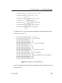
68000 assembler, a linker, and a downloader. The SDS assembler allows you to define
up to 250 relocatable regions, identified by region names. These regions are mapped
into the target memory structure by the linker using a linker specification file. This file
allows you to map various regions to particular addresses and position them in ROM or
RAM as needed. The C compiler automatically splits output into five standard regions
for code, strings, constant data, initialized data, and uninitialized data which are named
code, string, const, data, and ram, respectively. The freeway/icpcode/proto_kit/icpnnnn1
directory contains a sample make file (makefile) and a sample linker specification file
(sps_2424.spc, sps_2432.spc, or sps_6000.spc) which can be used to build the
sps_fw_nnnn.mem image.
2.3 Interfacing to the Operating System
The assembly and C language interfaces to OS/Impact are described in the OS/Impact
Programmer Guide. The freeway/icpcode/proto_kit/src directory contains source code for
a C interface library (oscif.h and oscif.asm). The routines in this library are written
according to the subroutine calling conventions of the CrossCodeC compiler and can
be easily modified for most other C compilers or high-level language compilers.
The interface routines are necessary when accessing OS/Impact from C language routines for two reasons. First, OS/Impact’s system calls are accessed through a software
trap instruction, which cannot be generated directly from C. Second, the subroutine
calling conventions of the CrossCodeC compiler (where parameters are passed mainly
on the stack) differ from those of the OS/Impact system calls (where parameters are
passed in registers). The interface routines must perform the necessary translations
before and after OS/Impact system calls.
The oscif.h file contains C structure definitions for all relevant operating system data
structures.
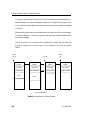
1. icpnnnn refers to the icp2424, icp2432, or icp6000 directory.
36
DC 900-1338I
2: Software Development for the ICP
For programs written in assembly language, the freeway/icpcode/proto_kit/src directory
includes the files sysequ.asm, with OS/Impact system call macros, and oscif.asm, with
assembly language definitions of OS/Impact data structures. These files are in a format
compatible with the CrossCodeC assembler, but can also be modified for use by other
assemblers.
2.4 Motorola 68xxx Programming Environment
The Motorola 68xxx CPU is a 32-bit microprocessor with 32-bit registers, internal data
paths, and addresses that provides a four-gigabyte direct addressing range. If your
application code will be written in assembly language, you will find the MC68000 Family Reference Manual (Motorola) indispensable. It contains information on the generalpurpose and special registers, addressing modes, instruction set, and exception processing. When programming in a higher-level language, most aspects of the processor are
relatively transparent. The following sections present some general information to help
you understand the 68xxx programming environment.
2.4.1 Processor Privilege States
The 68xxx supports two privilege levels: user and supervisor. On the ICP, OS/Impact
operates in supervisor state, as do all interrupt service routines and certain sections of
the application code. All tasks (including the system-level timer) operate in user state,
where certain operations are not allowed. See the MC68000 Family Reference Manual
(Motorola) for additional information.
2.4.2 Stack Pointers
The 68xxx special registers include three stack pointers: user (USP), master (MSP), and
interrupt (ISP). When the M-bit in the status register is set to zero, only the USP and
ISP are used. The ICP always operates in this mode, and user code must never set the
M-bit to one.
DC 900-1338I
37
Protocol Software Toolkit Programmer Guide
In user state, the USP is the current stack pointer. In supervisor state, the ISP (usually
called the system stack pointer, or SSP) is current. The current stack pointer is swapped
automatically by the processor into general register A7 when the privilege level changes,
so that register A7 is always used as the stack pointer, regardless of the processor’s state.
A stack pointer is pre-decremented when an element is added to the stack (pushed) and
post-incremented when an element is removed (popped). Stacks therefore grow from
higher to lower memory addresses, and the stack pointer always contains the address of
the element currently at the top of the stack.
During its initialization, OS/Impact allocates space for the system stack and initializes
the SSP. The system stack is used whenever the processor is in supervisor state. This
includes system calls and all interrupt service routines, including those associated with
user applications.
You must allocate stack space for each application task you create and specify the initial
stack pointer in the task initialization structure (see Section 4.2.2 on page 72). The initial stack pointer should be specified as the ending address of the stack space plus one.
For example, if a task’s stack space is 0x40016000 through 0x400163FF, the initial stack
pointer should be specified as 0x40016400. OS/Impact saves this initial value in the task
control block as the current stack pointer. When the task is dispatched, OS/Impact initializes the USP to the stack address saved in the task control block. When the task is
preempted, the task’s state (the contents of the general registers) is saved on its stack
and the current USP is again saved in the task control block.
When allocating a task’s stack, you must consider the space required at the deepest level
of nested subroutine calls, and allow 66 bytes for the registers saved when the task is
preempted. You need not allocate additional stack space for interrupt service routines,
as the USP is not used for interrupt processing.
38
DC 900-1338I
2: Software Development for the ICP
Note
The stack spaces are defined in the linker specification file
freeway/icpcode/proto_kit/icpnnnn1/sps_nnnn.spc.
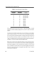
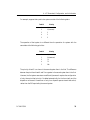
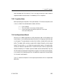
2.4.3 Exception Vector Table
On the 68xxx, interrupts and traps are processed through an exception vector table. The
68xxx vector base register points to the exception vector table, which contains 256 longword (four-byte) vectors. The vector base register is not accessible in user state, so
OS/Impact provides the base address of the exception vector table in its system address
table. (See the OS/Impact Programmer Guide.)
The MC68000 Family Reference Manual (Motorola) lists vector assignments as defined
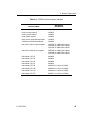
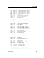
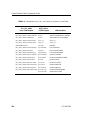
by the 68xxx CPU. Table 2–1 lists the vectors that are reserved for use by Protogate’s
system software.
To install an interrupt service routine (ISR) for a particular device, multiply the vector
number by four to obtain the vector offset, add the offset to the base address of the
exception vector table, and store your ISR entry point at the resulting address.
When the device generates an interrupt, it supplies the 68xxx CPU with the eight-bit
vector number, which the CPU multiplies by four to obtain a vector offset, then adds
the contents of the vector base register to obtain the vector address at which your ISR
entry point is stored. When interrupt servicing is complete, the ISR must terminate
with a “return from ISR” (s_iret) system call (described in the OS/Impact Programmer
Guide) if the interrupt requires that system services be invoked. Otherwise, a return
from exception (RTE) is sufficient.
1. nnnn stands for 2424, 2432, or 6000.
DC 900-1338I
39
Protocol Software Toolkit Programmer Guide
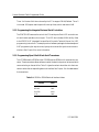
Table 2–1: Vectors Reserved for System Software
Vector Number
(Decimal)
Vector Offset
(Hexadecimal)
25
64
Auto vector level 1
26
68
Auto vector level 2
27
6C
Auto vector level 3
28
70
Auto vector level 4
32
80
TRAP # 0
33
84
TRAP # 1
34
88
TRAP # 2
35
8C
TRAP # 3
36
90
TRAP # 4
37
94
TRAP # 5
47
BC
TRAP # 15
Function
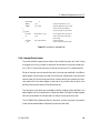
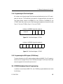
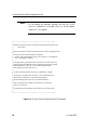
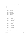
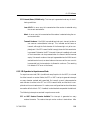
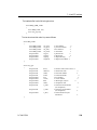
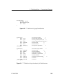
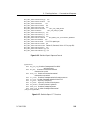
When programming interrupt service routines in a high-level language, it is usually
necessary to provide an assembly language “shell” for the ISR in order to save certain
registers.
For example, the CrossCodeC compiler saves on entry and restores on exit all registers
used in a subroutine except D0, D1, A0, and A1, which are considered working registers. The calling code must save these registers, if necessary, before making a subroutine
call. These calling conventions, however, are not sufficient for ISRs. An ISR is not
“called” in the ordinary sense; it interrupts code that might currently be using the working registers. The ISR must, therefore, save those registers as well.
Because many compilers cannot distinguish between an ordinary subroutine and an
interrupt service routine, the programmer must provide an assembly language shell to
save the working registers on entry and restore them at completion of the ISR. (Note
that it is the address of the shell rather than the high-level language routine that must
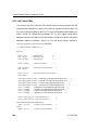
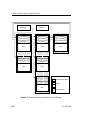
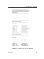
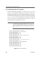
be stored in the appropriate vector of the exception vector table.) Figure 2–1 shows a
sample assembly language shell.
40
DC 900-1338I
2: Software Development for the ICP
SECTION
XREF
XDEF
*
*
_isr_shell
movem.l
jsr
*
movem.l
s_iret
9
_Cisr
_isr_shell
d0/d1/a0/a1,-(sp)
_Cisr
(sp)+,d0/d1/a0/a1
external reference to C isr
external definition for C code
which stores this address
in the exception vector table
save registers not saved by C
call C routine for interrupt
processing
restore registers
return from isr (system call)
Figure 2–1: Assembly Language Shell
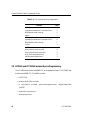
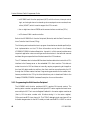
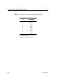
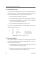
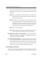
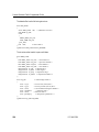
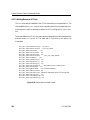
2.4.4 Interrupt Priority Levels
The Motorola 68xxx supports seven levels of prioritized interrupts, with level 7 being
the highest priority. Any number of devices can be chained to interrupt at the same priority. Table 2–2 shows the interrupt priorities for the various ICP’s hardware devices.
When an interrupt occurs at a particular priority, the interrupt mask field in the 68xxx’s
status register is set to the priority level of that interrupt, causing other interrupts at the
same or lower priorities to be ignored. When interrupt servicing is complete, the interrupt mask level in the status register is returned to its previous value, at which time
pending interrupts at lower priorities can be serviced.
The interrupt priority level can be changed by directly modifying the mask field in the
status register, but this is possible only in supervisor state. OS/Impact includes a system
call that can be called from the task level to modify the interrupt priority level.
The MC68000 Family Reference Manual (Motorola) contains important information
that should be studied before implementing interrupt-level code.
DC 900-1338I
41
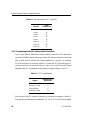
Protocol Software Toolkit Programmer Guide
Table 2–2: ICP Interrupt Priority Assignments
Device(s)
Level
ICP2424
Integrated Universal Serial Controllers (IUSC)
6
68340 periodic timer interrupt
5
ISAbus
5
ICP2432
Integrated Universal Serial Controllers (IUSC)
6
68349 periodic timer interrupt
5
PCIbus
5
ICP6000
Direct memory access controller
6
Serial communications controllers
5
Multi-function peripheral timer
5
VMEbus slave interface device
2
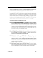
2.5 ICP2424 and ICP2432 Hardware Device Programming
The ICP2424 uses the Motorola 68340 CPU, an integrated processor. The ICP2432 uses
the Motorola 68349 CPU. The 6834x includes:
•
a CP32 CPU
•
a two-channel DMA controller
•
a
two-channel
universal
synchronous/asynchronous
receiver/transmitter
(USART)
42
•
a periodic interrupt timer
•
two counter/timers
DC 900-1338I
2: Software Development for the ICP
In addition to the Motorola 6834x, the ICP2424 and ICP2432’s programmable devices
include:
•
two, four, or eight Z16C32 integrated universal serial controllers (IUSCs) with
integral DMA for the ICP2432 or four IUSCs for the ICP2424
•
Sipex’s SP502 (ICP2424) or SP504 (ICP2432) multi-mode serial transceivers
•
a test mode register
•
an LED register
Note
The 8-port ICP2432 only supports EIA-232.
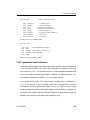
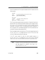
2.5.1 Programming the 68340/68349
The ICP2424 does not use the 68040’s two-channel DMA controller. The ICP2432 uses
the 68349’s two-channel DMA controller for PCIbus transfers.
Both 2424
The 6834x’s serial port A is used as a console port. The SingleStep debugger uses vector and 2432 have
red/green
0x4c for serial port A interrupts. Serial port B’s control signals are used to control the LEDs.
red and green LEDs on the mounting bracket. Table 2–3 contains the information
needed to turn the green and red LEDs on and off.
Table 2–3: LED Control Information
DC 900-1338I
Address
Value
Operation
0xee00f71e
0x40
Green LED on
0xee00f71e
0x10
Red LED on
0xee00f71f
0x40
Green LED off
0xee00f71f
0x10
Red LED off
43
Protocol Software Toolkit Programmer Guide
Timer 1 of the two 8-bit timers is used by the ICP to support DRAM/Refresh. Timer 2
is not used. OS/Impact uses the periodic interrupt timer, which uses vector 0x40.
2.5.2 Programming the Integrated Universal Serial Controllers
The Z16C32 IUSCs are used to control the ICP’s serial ports. Each IUSC controls transmit and receive operations for one port. The IUSC also includes a DMA facility. Refer
to the Z16C32 IUSC Integrated Universal Serial Controller Technical Manual, for IUSC
programming instructions. The sample protocol software package includes examples of
IUSC programming for asynchronous, byte synchronous and bit synchronous communications. See Chapter 6 for more information.
2.5.3 Programming Sipex’s Multi-Mode Serial Transceivers
The ICP2424 uses the SP502 and the ICP2432 uses the SP504 multi-mode serial transceiver. These transceivers allow software to select the electrical protocol to be used while
communicating on the serial line. Table 2–4 gives the value to be written into the transceiver to select the corresponding electrical interface. See Chapter 3 for the addresses of
the transceivers.
Table 2–4: SP502 or SP504 Electrical Interface Values
Interface
44
Value
RS-232
0x02
RS-449
0x0c
EIA-530
0x0d
V.35
0x0e
DC 900-1338I
2: Software Development for the ICP
2.5.4 Programming the Test Mode Register
All modem control signals except Test Mode are handled directly by the IUSC associated with the port. The Test Mode input status for all supported ports is through the
Test Mode register located at 0x1808000 for the ICP2424 or 0x1810000 for the
ICP2432. When a bit is set to one, the Test Mode signal is asserted on the serial line. See
Figure 2–2 for the ICP2424 or Figure 2–3 for the ICP2432.
Address = 0x1808000, byte wide, read only
Reserved
3
2
1
0
Figure 2–2: Test Mode Register, ICP2424
Address = 0x1810000, byte wide, read only
7
6
5
4
3
2
1
0
Figure 2–3: Test Mode Register, ICP2432
2.5.5 Programming the LED Register (ICP2424 only)
The byte-wide write-only LED register resides at address 0x410000. The LED register is
used to control the eight LEDs on the ICP2424 board’s edge. The LEDs are illuminated
when the register bit is 0 and off when the bit is 1.
2.6 ICP6000 Hardware Device Programming
In addition to the Motorola 68020 CPU, the ICP6000’s programmable devices include
the following:
DC 900-1338I
45
Protocol Software Toolkit Programmer Guide
•
a MC68901 multi-function peripheral (MFP) with four timers, interrupt control
logic, and a single-channel universal synchronous/asynchronous receiver/transmitter (USART) which is used to support the ICP’s console
•
four or eight two-channel Z8530 serial communications controllers (SCCs)
•
a 32-channel DMA transfer controller
Refer to the MC68901 Multi-function Peripheral (Motorola) and the Serial Communications Controller User’s Manual (Zilog).
The following sections describe how to program these devices as related specifically to
their implementation on the ICP. More information can be found in the Freeway
ICP6000R/ICP6000X Hardware Description. Appendix A of this manual provides some
important application notes correcting errors and omissions in the technical manuals
and describing some peculiarities of the devices and the ICP hardware.
The ICP hardware also includes a VMEbus slave interface device that controls the ICP’s
interface to the Freeway server or the embedded ICP’s client machine. This device is
under the control of XIO and does not normally require programming at the application level. All data transfers to and from the client machine are performed by the ICP
through the VMEbus master interface. Programming parameters for the master interface are provided to the ICP by the client-side driver prior to download. Refer to the
Freeway ICP6000R/ICP6000X Hardware Description for more information.
2.6.1 Programming the Multi-function Peripheral
The MC68901 multi-function peripheral (MFP) requires 16 interrupt vectors. The
starting vector number is programmed using the MFP’s vector register and must be an
even multiple of 16. The In-service Register Enable bit in the vector register must be set
(that is, OR the vector number with 8 before storing it in the vector register).
OS/Impact uses MFP timer channel A. The PTBUG debugging tool uses channel D as
the baud rate generator for the MFP’s serial port and uses the MFP’s USART to control
46
DC 900-1338I
2: Software Development for the ICP
the console port. Timer channels B and C are dedicated to hardware functions. Do not
change the configuration of the timer channels.
The MFP contains 24 byte-wide registers beginning at the MFP base address
(0x20000000). The MFP’s eight channels of external interrupt control are used to provide SCC interrupts. The MFP must be initialized appropriately before using SCC
interrupts.Table 2–5 shows the recommended setup.
Table 2–5: Setup for MFP Initialization
Register
Value
(Hexadecimal)
VR
48
DDR
00
AER
00
IPRA
00
IPRB
00
IERA
C0
IERB
CF
IMRA
C0
IMRB
CF
With the MFP vector register set to 0x48, the MFP’s base vector is 0x40 and the eight
SCCs interrupt at the vector numbers shown in Table 2–6.
Refer to the MC68901 Multi-function Peripheral (Motorola) for MFP programming
instructions. The sample protocol software package includes code to perform MFP initialization and handle MFP control of SCC interrupts.
DC 900-1338I
47
Protocol Software Toolkit Programmer Guide
Table 2–6: Vector Numbers for SCC Interrupts
Channels
Vector
(Hexadecimal)
0 and 1
40
2 and 3
41
4 and 5
42
6 and 7
43
8 and 9
46
10 and 11
47
12 and 13
4E
14 and 15
4F
2.6.2 Programming the Serial Communications Controllers
Four or eight Z8530 or Z85230 serial communications controllers (SCCs) are used to
control the ICP6000’s eight or sixteen ports. Each SCC has two channels, A and B, and
each channel controls transmit and receive operations for one port. For example,
SCC01 controls port 0 on channel A and port 1 on channel B, SCC23 controls port 2 on
channel A and port 3 on channel B, and so on. Table 3–4 on page 55 lists the SCC base
addresses. Each SCC is accessed through the eight-bit registers shown in Table 2–7.
Table 2–7: SCC Access Registers
Register
Offset from SCC
Base Address
Channel A Data
0
Channel A Control
1
Channel B Data
2
Channel B Control
3
Each channel of the SCC contains 16 eight-bit write registers, numbered 0 through 15,
and nine eight-bit read registers, numbered 0, 1, 2, 3, 8, 10, 12, 13, and 15. Write register
48
DC 900-1338I
2: Software Development for the ICP
8 and read register 8 (the transmit and receive data buffers) are accessed directly
through the channel’s data register. All other registers except Read and Write registers
(RRO and WRO) are accessed through the channel’s control register in two steps: a
write to select the actual register number, followed by a read or write to transfer the
data. RRO and WRO are accessible with a single transfer.
Note
These two steps must be done at CPU level 6 to lock out any ISRs
that might need to access the SCCs.
Refer to the Serial Communications Controller User’s Manual (Zilog) for SCC programming instructions. The sample protocol software package includes examples of SCC
programming for asynchronous, byte synchronous, and bit synchronous communications. See Chapter 6 for more information. Also see pointer array Z8530 *scc[] in
freeway/icpcode/proto_kit/src/spsstructs.h.
2.6.3 Programming the DMA Controller
The 32-channel direct memory access (DMA) controller is programmed using a single
byte-wide command register and, for each channel, a 32-bit memory address register
and a 32-bit terminal count register. Channels 0 through 15 are dedicated to receive
operations on serial ports 0 through 15, and channels 16 through 31 are likewise dedicated to transmit operations.
The command register is located at address 0x10000000. The memory address registers
begin at address 0x400FFF00. The terminal count registers begin at address
0x40xFFF80. (x is 0 for a 1 MB ICP, 3 for a 4 MB ICP, or 7 for a 8 MB ICP.) Only the
low-order 20 bits of the memory address and terminal count registers are valid, allowing an address range of 1 megabyte beginning at the base address of RAM
(0x40000000). Also see pointer array IO_DMA io_dma[3] in freeway/icpcode/
proto_kit/src/spsstructs.h.
DC 900-1338I
49
Protocol Software Toolkit Programmer Guide
Vector numbers 224–255 (0xE0–0xFF) are dedicated to DMA controller channels 0–31,
respectively.
Refer to the Freeway ICP6000R/ICP6000X Hardware Description for DMA programming instructions. The sample protocol software package includes examples of DMA
programming for transmit and receive operations.
50
DC 900-1338I
Chapter
3
Memory Organization
This chapter describes the memory maps for the ICP2424, ICP2432, and ICP6000.
3.1 ICP2424
The 128-kilobyte EPROM on the ICP2424 is located at address 0x0000. The EPROM
contains the diagnostics, Peeker debugging tool, and boot loader.
One megabyte of dynamic random access memory (DRAM) starts at 0x00800000. This
DRAM is only accessible to the MC68340 and is used for program and private data
space that does not need to be accessed by any of the devices in the Z-bus space. The
Z-bus space contains one megabyte of DRAM as shared memory. The shared memory
starts at 0x01000000 as seen from the MC68340. The shared memory is to buffer data
between the ISAbus and the IUSCs. The ISAbus has access to that memory at the locations defined in Table 3–1. The IUSCs’ DMA controllers see the shared memory at
0x00000000.
Addresses 0x00800000 to 0x00801200 of the private memory are reserved. The system
services module (containing the operating systems and XIO) is loaded beginning at
address 0x00801200. As described in Section 4.3.1 on page 75, the fixed memory
requirements for a particular version of the system services module are specified in the
spsdefs.h file, and additional memory required for the OS/Impact’s configurable data
section depends on the system configuration. The rest of the DRAM is available for user
applications.
DC 900-1338I
51
Protocol Software Toolkit Programmer Guide
The ICP2424 Hardware Description and Theory of Operation provides a complete memory map. Table 3–2 summarizes the hardware device and register addresses.
Table 3–1: ICP2424 Memory Address Registers Base Address
Physical
Device ID
Address
(Hexadecimal)
0
00080000
1
00090000
2
000A0000
1
000B0000
a
000C0000
5a
000D0000
6a
000E0000
72
000F0000
3
4
1
Physical device IDs 4, 5, 6, and 3 are
preferred for logical ICPs 0, 1, 2, and 3,
respectively.
2
Physical device ID 7 cannot be used in
Freeway 1100 because of a motherboard device conflict.
Table 3–2: ICP2424 Device and Register Addresses
Device or Register
52
Base Address
(Hexadecimal)
LED on board edge
00410000
Base address of IUSC for Port 0
01800000
Base address of IUSC for Port 1
01801000
Base address of IUSC for Port 2
01802000
Base address of IUSC for Port 3
01803000
SP502 for Port 0
01804000
SP502 for Port 1
01805000
SP502 for Port 2
01806000
SP502 for Port 3
01807000
DC 900-1338I
3: Memory Organization
3.2 ICP2432
The 128-kilobyte EPROM on the ICP2432 is located at address 0x0000. The EPROM
contains the diagnostics, Peeker debugging tool, and boot loader.
Two or eight megabytes of dynamic random access memory (DRAM) start at
0x00800000. Memory addresses 0x00800000 to 0x00801200 are reserved. The system
services module (containing the operating systems and XIO) is loaded beginning at
address 0x00801200. As described in Section 4.3.1 on page 75, the fixed memory
requirements for a particular version of the system services module are specified in the
spsdefs.h file, and additional memory required for the OS/Impact’s configurable data
section depends on the system configuration. The rest of the DRAM is available for user 11/14/97: This
manual isn’t
finished yet;
Scott has it.
Make sure it
have a
The ICP2432 Hardware Description and Theory of Operation provides a complete mem- does
complete
memory map.
ory map. Table 3–3 summarizes the hardware device and register addresses.
applications.
Table 3–3: ICP2432 Device and Register Addresses
Device or Register
DC 900-1338I
Base Address
(Hexadecimal)
Base address of IUSC for Port 0
01800000
Base address of IUSC for Port 1
01810000
Base address of IUSC for Port 2
01820000
Base address of IUSC for Port 3
01830000
Base address of IUSC for Port 4
01840000
Base address of IUSC for Port 5
01850000
Base address of IUSC for Port 6
01860000
Base address of IUSC for Port 7
01870000
SP504 for Port 0
01880000
SP504 for Port 1
01890000
SP504 for Port 2
018A0000
SP504 for Port 3
018B0000
53
Protocol Software Toolkit Programmer Guide
3.3 ICP6000
The 64-kilobyte PROM on the ICP6000 is located at address 0x0000. The PROM contains the diagnostics, PTBUG debugging tool, and boot loader.
Socket U19 on the ICP is available for a user-added PROM of up to 256 kilobytes. If
installed, this PROM is addressed beginning at 0x20000.
One, four, or eight megabytes of dynamic random access memory (DRAM) starts at
0x40000000. Addresses 0x40000000 to 0x40001200 are reserved for PTBUG’s data area.
The system services module (containing the operating system and XIO) is loaded
beginning at address 0x40001200. As described in Section 4.3.1 on page 75, the fixedmemory requirements for a particular version of the system services module are specified in the spsdefs.h file, and the additional memory required for OS/Impact’s configurable data section depends on the system configuration. The rest of the RAM is
available for user applications.
The Freeway ICP6000R/ICP6000X Hardware Description provides a complete memory
map. Table 3–4 in this chapter summarizes the addresses of hardware registers and the
base addresses of hardware devices.
The Freeway server communicates with the ICP6000 via 16 mailbox registers. Table 3–5
defines the base of these registers as seen on the VMEbus.
54
DC 900-1338I
3: Memory Organization
Table 3–4: ICP6000 Device and Register Addresses
Base Address
(Hexadecimal)
Device or Register
DMA command register
10000000
General control register 0
10000001
General control register 1
10000002
General status register 0
10000003
Multi-function peripheral base address
20000000
VMEbus slave interface base address
30000000
Base of DMA memory address registers
400FFF00 (for 1 MB DRAM system)
403FFF00 (for 4 MB DRAM system)
407FFF00 (for 8 MB DRAM system)
Base of DMA terminal count registers
400FFF80 (for 1 MB DRAM system)
403FFF80 (for 4 MB DRAM system)
407FFF80 (for 8 MB DRAM system)
Base address of SCC01
60000000
Base address of SCC23
60000004
Base address of SCC45
60000008
Base address of SCC67
6000000C
Base address of SCC89
60000010 (for a 16-port ICP6000)
Base address of SCCAB
60000014 (for a 16-port ICP6000)
Base address of SCCCD
60000018 (for a 16-port ICP6000)
Base address of SCCEF
6000001C (for a 16-port ICP6000)
DC 900-1338I
55
Protocol Software Toolkit Programmer Guide
Table 3–5: ICP6000 VME Slave Address Registers Base Address
Physical Device
ID
0
F0001
12
F200
2b
F400
3b
F600
b
F800
4
1
Address
(Hexadecimal)
5
FA00
6
FC00
7
FE00
VME short address space.
2
Physical device IDs 1, 2, 3, and 4 are preferred
for logical ICPs 0, 1, 2, and 3, respectively.
56
DC 900-1338I
Chapter
4
ICP Download,
Configuration,
and Initialization
Section 4.1 of this chapter describes additional download considerations not covered in
the Freeway User Guide or the embedded ICP user guide so you can download the toolkit protocol software with or without the Software Development Systems (SDS) debug
monitor. Section 4.2 describes configuration and initialization issues. Section 4.3
describes the relationship between the system configuration and OS/Impact’s memory
requirements and performance.
4.1 Download Procedures
4.1.1 Freeway Server Download Procedure
The protocol software toolkit installation procedure is described in the Freeway User
Guide. On UNIX systems, all subdirectories are installed by default under the directory
named /usr/local/freeway. On VMS systems, all subdirectories are installed by default
under the directory named SYS$SYSDEVICE:[FREEWAY]. On Windows NT systems,
all subdirectories are installed by default under the directory named c:\freeway. It is
highly recommended that you use these default directories.
During the software installation, boot, and test procedures described in the Freeway
User Guide, the non-debug version of the toolkit software is downloaded to the ICP.
However, during toolkit application development, you must modify your Freeway
server boot configuration file and then reboot the Freeway server to download and start
the debug monitor module. Section 4.1.1.1 and Section 4.1.1.2 describe the files and
modifications required to download with or without the Software Development Systems (SDS) debug monitor.
DC 900-1338I
57
Protocol Software Toolkit Programmer Guide
The Freeway server boot configuration file, used to control the download procedure, is
covered in detail in the Freeway User Guide. The boot configuration file is located in the
freeway/boot directory (for example, bootcfg.vme for a Freeway 2000/4000/8800). The
download script file parameter (download_script) in the boot configuration file specifies
the modules to be downloaded to the ICP and the memory location for each module.
You must modify the download_script parameter as described in Section 4.1.1.2 when
you need to change between debug and non-debug operation.
When you reboot the Freeway server, the modules are downloaded to the ICP in two
stages. First, the server software uses a file transfer program to download the modules
to the server’s local memory. The modules are then transferred across the ISAbus,
PCIbus, or VMEbus to the ICP.
PCIbus and VMEbus transfers are handled by the ICP’s CPU. The server software provides the location and size of the binary images and the address in the ICP’s RAM at
which the modules should be loaded, and then signals the ICP to begin the download
process.
ISAbus transfers are handled by the server’s CPU. The entire image is placed in shared
memory, then the ICP moves the image to private memory.
58
DC 900-1338I
4: ICP Download, Configuration, and Initialization
4.1.1.1 Downloading Without the Debug Monitor
Under normal operations you download the toolkit software without the debug monitor. The following files are required:
spsload
This is the download script file. You must specify this file name
for the download_script parameter in your boot configuration
file. The file is in the freeway/boot directory.
xio_2424.mem,
xio_2432.mem, or
xio_6000.mem
This is the system-services module containing the OS/Impact
sps_fw_2424.mem,
sps_fw_2432.mem, or
sps_fw_6000.mem,
This is the toolkit sample protocol software (SPS) module.
operating system kernel, timer task, and XIO. This file is in the
freeway/boot directory.
This file is in the freeway/icpcode/proto_kit/icpnnnn1 and
freeway/boot directories. Source files are in the freeway/
icpcode/proto_kit/src directory. If you make changes to the
source files, you must rebuild the sps_fw_nnnn.mem module
before downloading. The makefile is in the freeway/
icpcode/proto_kit/icpnnnn directory.
The protocol toolkit developer may wish to change the download script file to download the sps_fw_nnnn2.mem file directly from freeway/icpcode/proto_kit/icpnnnn; otherwise, you must copy any new versions of the protocol sps_fw_nnnn.mem file after each
rebuild.
Figure 4–1 shows the spsload download script file that downloads the toolkit software
when you reboot the Freeway server. Uncomment the “normal” lines associated with
the type of ICP you are using and modify path names as needed. Do not change the
memory locations (such as 40001200) for the LOAD commands.
1. icpnnnn refers to the icp2424, icp2432, or icp6000 directory.
2. nnnn refers to the icp2424, icp2432, or icp6000.
DC 900-1338I
59
Protocol Software Toolkit Programmer Guide
Note
Do not remove the comment indicator (#) from the “LOAD
buffer.size” statement if the buffer size is to be the default
(Section 4.1.3 on page 64).
#----------------------------------------------------------------------------#
#
# spsload - Protocol load file to be used to load the SPS toolkit protocol
#
onto an ICP.
#
# Protocol load files are referenced from the server boot configuration file
#
# load files contain LOAD and INIT commands.
# LOAD <fully qualified path name to the .mem file> <load address>
# INIT <initialization address>
#
# If no path name is provided for the .mem files to be loaded, Freeway
# searches the System Boot Directory specified in the Freeway System
# Boot Parameters for the file. A fully qualified path name to
# each file may be used if desired. e.g.
#
# LOAD /usr/local/freeway/boot/sps_fw_2424.mem 818000
#
# for the "sps_fw_2424.mem" file in the "/usr/local/freeway/boot"
# directory on a UNIX host. (see the bootcfg example
# file for example path syntax for various host machines)
#
# Each sps load file must contain an osimpact (xio) .mem file
# and an sps .mem file
#
# Uncomment the ICP load/init section below for your ICP model.
#
#-----------------------------------------------------------------------------#
Figure 4–1: Protocol Toolkit Download Script File (spsload)
60
DC 900-1338I
4: ICP Download, Configuration, and Initialization
#
# SNMP support notes for SPS toolkit protocol software product SP-000-6013:
#
# When using Freeway server SP-000-6055 Rev M (or later revision)
# LOAD the appropriate snmp .mem file show in the samples below.
#
# When using Freeway server SP-000-6055 Rev L (or prior revision)
# DO NOT load the appropriate snmp .mem file show in the samples below.
#
#-----------------------------------------------------------------------------#
#
#
# the example below is for icp2424 normal operation
#
#LOAD xio_2424.mem
801200
#LOAD snmp2424.mem
810000
#LOAD sps_fw_2424.mem 818000
#LOAD buffer.size
1001000
#INIT
818000
#
# the example below is for icp2424 debug operation
# (SNMP support is not recommended for debug operation)
#
#LOAD xio_2424.mem
801200
#LOAD icp2424c.mem
812000
#LOAD sps_fw_2424.mem 818000
#LOAD buffer.size
1001000
#INIT
812000
#
# the example below is for icp2432 normal operation
#
#LOAD xio_2432.mem
801200
#LOAD snmp2432.mem
810000
#LOAD sps_fw_2432.mem 818000
#LOAD buffer.size
9d0000
#INIT
818000
#
# the example below is for icp2432 debug operation
# (SNMP support is not recommended for debug operation)
#
#LOAD xio_2432.mem
801200
#LOAD icp2432c.mem
812000
#LOAD sps_fw_2432.mem 818000
#LOAD buffer.size
9d0000
#INIT
812000
#
Figure 4–1: Protocol Toolkit Download Script File (spsload) (Cont’d)
DC 900-1338I
61
Protocol Software Toolkit Programmer Guide
# the example below is for icp6000 normal operation
#
#LOAD xio_6000.mem
40001200
#LOAD snmp6000.mem
40010000
#LOAD sps_fw_6000.mem 40018000
#LOAD buffer.size
400d0000
#INIT
40018000
#
# the example below is for icp6000 debug operation
# (SNMP support is not recommended for debug operation)
#
#LOAD xio_6000.mem
40001200
#LOAD icp6000c.mem
40012000
#LOAD sps_fw_6000.mem 40018000
#LOAD buffer.size
400d0000
#INIT
40012000
#
Figure 4–1: Protocol Toolkit Download Script File (spsload) (Cont’d )
62
DC 900-1338I
4: ICP Download, Configuration, and Initialization
4.1.1.2 Downloading With the Debug Monitor
During application development you must download the toolkit software with the
debug monitor. The SDS tools are not compatible with VMS platforms, but UNIX,
DOS and Windows versions are available. If you are a VMS user, you can develop and
debug your software with these tools using a PC running under DOS or Windows and
a utility to transport files from the PC to the VMS system. Chapter 5 explains how to
use the SDS debug tools.
The following files are required:
spsload
This is the download script file. You must specify this file name
for the download_script parameter in your boot configuration
file. The file is in the freeway/boot directory.
icp2424c.mem,
icp2432c.mem or
icp6000c.mem
This module contains the source-level debug monitor. This file
sps_fw_2424.mem,
sps_fw_2432.mem, or
sps_fw_6000.mem
This is the toolkit sample protocol software (SPS) module. This
is in the freeway/icpcode/proto_kit/icpnnnn1 directory.
file is in the freeway/icpcode/proto_kit/icpnnnn1 directory. Source
files are in the freeway/icpcode/proto_kit/src directory. If you
make changes to the source files, you must rebuild the
sps_fw_nnnn.mem module before downloading. The makefile is
in the freeway/icpcode/proto_kit/icpnnnn directory.
Figure 4–1 on page 60 shows the spsload download script file that downloads the toolkit
software when you reboot the Freeway server. Uncomment the “debug” lines associated
with the type of ICP you are using and modify path names as needed. Do not change the
memory locations (such as 40001200) for the LOAD commands.
1. icpnnnn refers to the icp2424, icp2432, or icp6000 directory.
DC 900-1338I
63
Protocol Software Toolkit Programmer Guide
When the SDS debug monitor is downloaded along with other executable image files,
the placement and order of execution of the downloaded code is different. The download addresses of the modules can differ, and the debug module will be first to execute.
Note that the monitor must use RAM from 0x812000 to 0x818000 on the ICP2424 or
ICP2432, and from 0x40012000 to 0x40018000 on the ICP6000.
4.1.2 Embedded ICP Download Procedure
As with the Freeway server environment described in Section 4.1.1, the freeway/boot/
spsload file defines the files to be downloaded to the embedded ICP. Uncomment the
11/14/97:
Right now the
only embedded
product we
have runs on
Windows NT.
When we get
products for
VMS and DEC
UNIX, etc., this
section will
have to be
expanded.
lines associated with the type of ICP you are using and modify path names as needed.
Do not change the memory locations (such as 40001200) for the LOAD commands.
The ICPs are loaded by the program icpload (a Windows NT service) which is normally
executed during the start up of the client machine. During development, the ICPs may
be loaded or reloaded by running spsload.
4.1.3 ICP Buffer Size
The maximum ICP buffer size can be set at ICP download time by downloading a
“buffer size” file. A default buffer.size file is provided in the freeway/boot directory and
can be downloaded at the following addresses (as shown in Figure 4–1 on page 60):
ICP2424
ICP2432
ICP6000
0x01001000
0x009D0000
0x400D0000
To create your own buffer.size file:
1. Set your default directory to freeway/icpcode/proto_kit/buffer_size.
2. Compile and link the make_size utility program:
64
on Windows NT:
nmake -f makefile.nt
on UNIX:
make -f makefile.unix
on VMS:
@makefile
DC 900-1338I
4: ICP Download, Configuration, and Initialization
3. Run the make_size utility program, specifying the desired buffer size when
prompted.
4. Copy the new buffer.size file to the freeway/boot directory for subsequent downloads.
However, since in most cases the maximum buffer size is not changed, it is suggested
that the #define variable DEFAULT_FNAME be changed if the default size of 1024 is not
acceptable.
4.2 OS/Impact Configuration and Initialization
A complete ICP run-time system is composed of a system-services module and one or
more user-application modules. One of the user-application modules must include a
configuration table and a system task initialization routine. For example, the systemservices module provided with toolkit is the binary image file (xio_2424.mem,
xio_2432.mem, or xio_6000.mem), and the sample user-application modules are the
sample protocol software binary image (sps_fw_2424.mem, sps_fw_2432.mem, or
sps_fw_6000.mem).
The last step of the download script file specifies an entry point or start-up address for
execution of the downloaded code (see the INIT command in Figure 4–1). This entry
point must be the address of your system task initialization routine (or the address of
the icpnnnnc.mem debug module if you are running with the SDS debug monitor).
After download completes and control has been transferred to your task initialization
routine, system configuration and initialization begin as described in the remainder of
this section.
DC 900-1338I
65
Protocol Software Toolkit Programmer Guide
Figure 4–2 shows a sample memory layout that specifies the download and start-up
locations in the ICP2424’s RAM for the system-services module and sample protocol
application.
ICP2424 RAM
0x800000
Load systemservices module
(xio_2424.mem )
Reserved
0x801200
System-services Module
Reserved
0x812000
Load userapplication module
(sps_fw_2424.mem)
0x818000
Unused
Start of initialization
Task Initialization Routine
3159
User-application Module
Figure 4–2: ICP2424 Memory Layout with Application Only
66
DC 900-1338I
4: ICP Download, Configuration, and Initialization
Figure 4–3 shows a similar ICP2424 configuration consisting of the system-services
module, SDS debug monitor, and sample protocol application.
ICP2424 RAM
0x800000
Load systemservices module
(xio_2424.mem )
Reserved
0x801200
System-services Module
Load debug
monitor module
(icp2424c.mem)
Load userapplication module
(sps_fw_2424.mem)
Start of initialization
0x812000
SDS Debug Monitor
0x818000
Task Initialization Routine
3160
User-application Module
Figure 4–3: ICP2424 Memory Layout with Application and SDS Debug Monitor
DC 900-1338I
67
Protocol Software Toolkit Programmer Guide
Figure 4–4 shows a sample memory layout that specifies the download and start-up
locations in the ICP2432’s RAM for the system-services module and sample protocol
application.
ICP2432 RAM
0x800000
Load systemservices module
(xio_2432.mem)
Reserved
0x801200
System-services Module
Reserved
Load userapplication module
(sps_fw_2432.mem)
0x812000
Unused
0x818000
Start of initialization
Task Initialization Routine
3403
User-application Module
Figure 4–4: ICP2432 Memory Layout with Application Only
68
DC 900-1338I
4: ICP Download, Configuration, and Initialization
Figure 4–5 shows a similar ICP2432 configuration consisting of the system-services
module, SDS debug monitor, and sample protocol application.
ICP2432 RAM
0x800000
Load systemservices module
(xio_2432.mem)
Reserved
0x801200
System-services Module
Load debug
monitor module
(icp2432c.mem)
Load userapplication module
(sps_fw_2432.mem)
Start of initialization
0x812000
SDS Debug Monitor
0x818000
Task Initialization Routine
3404
User-application Module
Figure 4–5: ICP2432 Memory Layout with Application and SDS Debug Monitor
DC 900-1338I
69
Protocol Software Toolkit Programmer Guide
Figure 4–6 shows a sample memory layout that specifies the download and start-up
locations in the ICP6000’s RAM for the system-services module and sample protocol
application.
ICP6000 RAM
0x40000000
Load systemservices module
(xio_6000.mem)
Reserved for PTBUG
0x40001200
System-services Module
Reserved
0x40012000
Load userapplication module
(sps_fw_6000.mem)
0x40018000
Unused
Start of initialization
Task Initialization Routine
2520
User-application Module
Figure 4–6: ICP6000 Memory Layout with Application Only
70
DC 900-1338I
4: ICP Download, Configuration, and Initialization
Figure 4–7 shows a similar ICP6000 configuration consisting of the system-services
module, SDS debug monitor, and sample protocol application.
ICP6000 RAM
0x40000000
Load systemservices module
(xio_6000.mem)
Reserved for PTBUG
0x40001200
System-services Module
Load debug
monitor module
(icp6000c.mem)
Start of initialization
0x40012000
SDS Debug Monitor
Load userapplication module
(sps_fw_6000.mem)
0x40018000
Task Initialization Routine
2521
User-application Module
Figure 4–7: ICP6000 Memory Layout with Application and SDS Debug Monitor
DC 900-1338I
71
Protocol Software Toolkit Programmer Guide
4.2.1 Configuration Table
The format of the configuration table is defined in the OS/Impact Programmer Guide
and consists of a list of configurable parameters and a list of task initialization structures.
OS/Impact creates its data structures based on the values of the parameters, then creates
a task for each task initialization structure.
Section 4.3 discusses the selection of appropriate configuration parameters. Figure 4–8
gives an example of a configuration table (not including the task initialization structures).
spscon
DC.W
DC.W
DC.W
DC.W
DC.W
DC.W
DC.W
DC.W
DC.L
8
8
164
10
8
0
100
8
0
number of tasks
number of priorities
number of queues
number of alarms
number of partitions
number of resources
tick length (milliseconds)
ticks for time slice
no user clock isr
Figure 4–8: Sample Configuration Table
4.2.2 Task Initialization Structures
A list of task initialization structures must follow the configuration table. The sample
configuration table shown previously in Figure 4–8 is repeated in Figure 4–9 with task
initialization structures for a sample task.
72
DC 900-1338I
4: ICP Download, Configuration, and Initialization
*
* Configuration Table
*
SECTION 14
XDEF
spscon
spscon
DC.W 8
DC.W 8
DC.W 164
DC.W 10
DC.W 8
DC.W 0
DC.W 100
DC.W 8
DC.L 0
number of tasks
number of priorities
number of queues
number of alarms
number of partitions
number of resources
tick length
ticks for time slice
no user clock isr
* Task Initialization Structure for the sample protocol task
DC.W SPSTSK_ID
task ID
DC.W 2
task priority
DC.L _spstsk
entry point address
DC.L RAM+$f8000
initial stack pointer
DC.W 0
time slice enabled
DC.W 0
filler (not used)
* Task Initialization Structure for the spshio (utility) task
DC.W SPSHIO_ID
task ID
DC.W 2
task priority
DC.L _spshio
entry point address
DC.L RAM+$fe000
initial stack pointer
DC.W 0
time slice enabled
DC.W 0
filler (not used)
* end of list
DC.W 0
end of list marker
Figure 4–9: Sample Configuration Table with Task Initialization Structures
DC 900-1338I
73
Protocol Software Toolkit Programmer Guide
4.2.3 Task Initialization Routine
You must supply a task initialization routine in one of the downloaded modules to be
used at the start-up of the ICP. The task initialization routine is executed at the completion of the download sequence and must perform the following functions:
1. Load the configuration table address into register A0.
2. Obtain the operating system initialization entry point address from the global system table at fixed address 0x801600 for the ICP2424 or ICP2432, or 0x40001600
for the ICP6000. Load this address into register A1.
3. Jump to the operating system initialization entry point “osinit.”
Figure 4–10 shows a sample task initialization routine associated with the configuration
table shown previously in Figure 4–9.
XDEF
_sysinit
move.l
move.l
jmp
#spscon,a0
RAM+$1600,a1
(a1)
_sysinit
address of config table
address of OS/Impact init
jump to OS/Impact's init
Figure 4–10: Sample Task Initialization Routine
4.2.4 OS/Impact Initialization
After your task initialization routine passes control to OS/Impact’s system initialization
entry point with the address of the configuration table in register A0, the “osinit” routine performs the following operations:
1. Initialize system stack pointer, exception vector table, and clock interrupts (using
the tick length specified in the configuration table).
2. Build data structures (task control blocks, queue control blocks, and so on)
according to parameters specified in the configuration table.
74
DC 900-1338I
4: ICP Download, Configuration, and Initialization
3. Allocate space for the timer task’s stack and create the task.
4. Use the task initialization structures included in the configuration table to create
one or more application tasks.
5. Transfer control to the kernel’s dispatcher to begin normal run-time operations.
The timer task is the highest priority in the system and is dispatched first. It performs
certain initialization procedures and then stops, after which the other tasks that were
created are dispatched in order of priority.
4.3 Determining Configuration Parameters
Although the design of a system should never be constrained by its configuration, when
available memory is extremely limited or system performance is critical, it might be
wise to consider the relationship between the system configuration and OS/Impact’s
memory requirements and performance. These relationships are discussed in the following sections.
4.3.1 OS/Impact Memory Requirements
OS/Impact requires memory space for code, system data, stacks, and the exception vector table. Some data requirements are fixed, and some are dependent on the system
configuration. The space required for the exception vector table, code, and fixed data
for a particular version of the operating system can be found in xio_nnnn.xrf for
xio_nnnn.mem. The number of bytes required for the system stacks and configurable
data structures can be calculated as shown in Table 4–1.
Table 4–2, which is based on the configuration shown previously in Figure 4–8 on
page 72, shows a sample calculation used to determine the total number of system data
bytes required. The total memory requirements for the system are calculated by adding
the total number of system bytes required to the ending address of the system services
module and rounding up, if necessary, to an even multiple of four bytes.
DC 900-1338I
75
Protocol Software Toolkit Programmer Guide
Table 4–1: System Data Requirements
Stack
Bytes Required
Supervisor stack
1024
Timer task’s stack
512
Task control blocks
Number of tasks x 24
Queue control blocks
Number of queues x 20
Partition control blocks
Number of partitions x 28
Resource control blocks
Number of resources x 16
Alarm control blocks
Number of alarms x 28
Task alarm control blocks
Number of tasks x 28
Dispatch queues
((Number of priorities + 1) x 8) + 4
Table 4–2: Sample Calculation of System Data Requirements
Stack
Bytes Required
Supervisor stack
1024
Timer task’s stack
512
Task control blocks
8 x 24
= 192
Queue control blocks
30 x 20
= 600
Partition control blocks
4 x 28
= 112
Resource control blocks
0 x 16
= 0
Alarm control blocks
10 x 28
= 280
Task alarm control blocks
8 x 28
= 224
Dispatch queues
((5 + 1) x 8) + 4 = 52
-----2996
or
0xBB4
76
DC 900-1338I
4: ICP Download, Configuration, and Initialization
Continuing this example, assume that the xio_6000.xrf file shows 0x400045BE as the
system services module ending address. When the module is downloaded, the exception vector table, fixed data, and code occupy 0x33BE bytes at memory locations
0x40001200 (starting load address) through 0x400045BE. After operating system initialization is finished using the configuration table in our example, an additional 0xBB4
bytes is used for system stacks and configurable variables. The first free byte following
system memory is then 0x400045BE + 0xBB4 + 2 (for an even multiple of four), or
0x40005174. This address can be verified by checking the gs_ramend field of the global
system table after the system has been downloaded and initialized. The global system
table is defined in the OS/Impact Programmer Guide.
4.3.2 Configuration and System Performance
The following fields of the configuration table define the number of control structures
to be allocated during system initialization:
cf_ntask
Task control blocks and task alarm control blocks
cf_nque
Queue control blocks
cf_nalarm
Alarm control blocks
cf_npart
Partition control blocks
cf_nresrc
Resource control blocks
As described in Section 4.3.2.1, the values of these fields, no matter how large, have no
effect on system performance. The cf_nprior field determines the number of task priorities in the system and affects performance as described in Section 4.3.2.2. The cf_ltick
field determines the length of a “tick” and the cf_lslice field determines the length of a
time slice. The relationships of these fields to system performance are discussed in
Section 4.3.2.3.
DC 900-1338I
77
Protocol Software Toolkit Programmer Guide
4.3.2.1 Number of Configured Task Control Structures
The cf_ntask field of the configuration table defines the number of task control blocks
to be allocated in the system. Task control blocks are allocated sequentially, forming an
array of structures. The task ID is used as an index into the array to locate a particular
task control block. Therefore, the processing time required to access any task control
block is fixed and is not dependent on the number of task control blocks in the system.
Likewise, and for the same reason, the number of queue control blocks, alarm control
blocks, partition control blocks, and resource control blocks has no effect on system
performance.
4.3.2.2 Number of Configured Priorities
The cf_nprior field of the configuration table determines the number of task priorities to
be defined. A dispatch queue is created for each priority. When the head pointer for a
particular dispatch queue is zero, the queue is empty (in other words, no task is scheduled for execution at that priority). When the head pointer is non-zero, it contains the
address of a task control block corresponding to a task that is scheduled for execution
at that priority. Whenever a task switch occurs, the system dispatcher tests the head
pointer of each dispatch queue, in order of priority, until a non-zero value is encountered, then dispatches the task indicated by the task control block address. Because the
dispatch queues are searched sequentially, a large number of priorities can adversely
affect system performance. There is no benefit to configuring more priorities than
required by the system design.
78
DC 900-1338I
4: ICP Download, Configuration, and Initialization
For example, suppose that a particular system consists of the following tasks:
Task ID
Priority
1
0 (timer task)
2
1 (reserved)
3
2
4
2
5
3
The operation of that system is no different than the operation of a system with the
same tasks at the following priorities:
Task ID
Priority
1
0 (timer task)
2
50 (reserved)
3
75
4
75
5
200
The priority of task 5 is no lower in the second system than in the first. The difference
between the priorities of tasks 1 and 2 is no greater in the second system than in the first.
However, the first system executes more efficiently because it requires the configuration
of only three priorities (priority 0 is added automatically for the timer task), and the
dispatcher must search a maximum of only four dispatch queues at each task switch,
rather than the 201 required by the second system.
DC 900-1338I
79
Protocol Software Toolkit Programmer Guide
4.3.2.3 Tick and Time Slice Lengths
Ticks measure the duration of alarms and the system’s time slice period. The cf_ltick
field of the configuration table specifies the length of a tick (1 to 222 milliseconds).
The length of a tick should be set to the smallest of the following values:
•
The minimum duration of any alarm in the system
•
The maximum acceptable error in an alarm duration
•
The desired time slice duration
Because each tick corresponds to a clock interrupt and involves processing by the clock
interrupt service routine, setting the tick length to a smaller value than is actually
required results in increased overhead and a degradation in system performance.
The cf_lslice field of the configuration table specifies the number of ticks for each time
slice. The time slice should be long enough to allow each task adequate processing time
before being preempted (in other words, to avoid “thrashing”), but not so long that any
task is able to prevent other tasks from executing in a timely fashion. (If no tasks in the
system are created with time slicing enabled, the length of the time slice is immaterial.)
80
DC 900-1338I
Chapter
5
Debugging
The debugging facilities available depend on whether Software Development Systems’
or some other cross development environment is being used. This chapter describes the
debugging facilities provided.
5.1 PEEKER Debugging Tool
PEEKER is a low-level peek and poke routine stored in the ICP2424 or ICP2432 PROM.
To use PEEKER, attach a 9600 b/s terminal directly to the ICP’s console port with the
console cable (and programmer’s module for the ICP2432) provided. To enter
PEEKER, type Control-C on the ICP’s console device, depress the black NMI switch on
the ICP2424’s card edge or the ICP2432’s programmer’s module, or execute a branch
or jump subroutine.
On entry, PEEKER displays the current values of the MC6834x’s register set.
PEEKER allows you to examine and modify locations in the ICP’s memory space by
bytes, words, or longwords.
In response to PEEKER’s prompt (pk>), enter Control-X to return to PEEKER’s caller
or to examine or modify a location.
To examine a location, enter:
•
the location’s address in hexadecimal
DC 900-1338I
81
Protocol Software Toolkit Programmer Guide
•
•
the access width (preceded by a semicolon):
•
b for byte
•
w for word
•
l for a longword
an equal sign
PEEKER then displays the address and contents of the given address in the form specified. The data may be modified by entering the new hexadecimal value followed by “^”,
“=”, a space, or a return as listed below.
^
Close current location, open previous location (in address
space), and display contents
=
Close current location, open current location (in address
space), and display contents
space
Close current location, open next location (in address space),
and display contents
return
Close current location and return PEEKER to its initial state,
waiting for a new address or Control-X
The following is a typical example:
pk> 1000;b=
0000_1000 01 n <return>
0000_1001 10 p <return>
0000_1000 01 <return>
pk>
PEEKER uses the following special characters to navigate and/or process inputs:
82
b
Open by byte
circumflex (^)
Close current location, open previous location (in address
space), and display contents
comma
Field delimiter between address and data
Control-X (exit)
Return to whomever called PEEKER
DC 900-1338I
5: Debugging
delete
Return PEEKER to its initial state
equal sign
Close current location, open current location (in address
space), and display contents
l
Open by longword
linefeed Control-J
Close current location, open next location (in address space),
and display contents
space
Close current location, open next location (in address space),
and display contents
n (next)
Close current location, open next location (in address space),
and display contents
p
Close current location, open previous location (in address
space), and display contents
period
Ignore, but echo
r or R
Publish registers and return PEEKER to initial state
<return> <esc>
Close and return to initial state
tab
Field delimiter between address and data
u (up)
Close current location, open previous location (in address
space), and display contents
underscore
Ignore, but echo
w
Open by word (default)
When PEEKER is entered, a brief summary of the special characters is published after
the register dump:
Peek & Poke <address>[,<data>][;<b, w or l>]<p, =, n, or <return>>
R/r = dump registers
ctrl/x = return to caller
The ICP2424 has “reset” and “abort” (NMI) pushbuttons on its circuit board. Pushing
the NMI button allows you to break out of loops and gain control even if the CPU is at
level seven.
Note
If the vector table entry for Autovector 7 or the vector base register
has been corrupted, the result of pushing the NMI button is indeterminate.
DC 900-1338I
83
Protocol Software Toolkit Programmer Guide
5.2 PTBUG Debugging Tool
The PTBUG debugging tool is available on the ICP6000. The PTBUG Debug and Utility
Program Reference Manual (PTI) (for the ICP6000) describes how to use the PTBUG
debugging tool included in PROM on every ICP.
To use PTBUG, attach a 9600 b/s terminal directly to the ICP’s console port with the
console cable provided. After the ICP has completed its power-on/reset diagnostics or
after the protocol application has been loaded, type Control-C to enter PTBUG. To
generate a breakpoint or “panic” trap from user applications, execute the 68020 assembly language instruction ILLEGAL to generate an illegal instruction trap or execute a
TRAP #15. The TRAP #15 can be continued by entering “go”.
For the ICP6000, an alternative is to connect the console via the programmer’s module
assembly (Protogate part number 10-000-0105). This device includes a circuit board
that supports reset and abort (NMI) signals. If your ICP software enters an endless loop,
the abort button can be used to force control to the PTBUG program. This allows you
to determine the location of the loop as well as the register contents, the memory contents, and so on.
Note
If the vector table entry for Autovector 7 or the vector base register
has been corrupted, the result of pushing the NMI button is indeterminate.
5.3 SingleStep Debugging Tool
The SingleStep Debugger for the 68000 Microprocessor Family manual describes how to
use the SingleStep debugging tool provided by Software Development Systems (SDS).
SingleStep is a symbolic debugger that allows developers to debug optimized C code for
68000-based target systems. VMS users must have a PC running DOS and a utility to
transport files from the PC to the VMS system.
84
DC 900-1338I
5: Debugging
Modules built with SDS development tools can be downloaded to the ICP along with
the SDS RAM-based debug monitor. This monitor runs on the ICP and communicates
with SingleStep through the 68901 MFP’s USART for the ICP6000 or the 6834x serial
port A for the ICP2424 and ICP2432. You must connect the USART by a cable from the
ICP’s console port to a serial port on the SingleStep client machine. SingleStep instructs
the monitor to set breakpoints, dump memory, view registers, and so on.
You must perform the following basic operations to use SingleStep:
1. In the spsload file, uncomment (remove the pound sign) the LOAD command for
the debug monitor, uncomment the INIT ...12000 command, and comment out
the INIT ...18000 command.
2. Install cables that connect the serial port on the SingleStep client machine with
the console port on the ICP.
3. Reboot the Freeway server or rerun icpload on the embedded product to download the SPS software and debug monitor to the ICP.
After the cables have been properly installed, you can test the configuration from
SingleStep. If the software was successfully downloaded, you can invoke SingleStep by
typing fm68k at the client machine’s prompt.
From the SingleStep prompt you can enter a transparent mode that echoes what the
monitor is transmitting. At the SingleStep prompt on a UNIX system, type the following command. (This option is not available in the DOS or Windows NT environment.)
SingleStep> debug -p /dev/ttya=9600 -T -
This tells SingleStep to use port /dev/ttya and to set the baud rate to 9600. The “-T”
parameter puts SingleStep into debug mode. At this point, the pattern “{#@<cr><lf>”
should appear. If this pattern does not appear, make sure the cables are connected correctly, then type the command again. To verify the data path to the ICP, enter {#}. The
ICP should then respond with {#+.
DC 900-1338I
85
Protocol Software Toolkit Programmer Guide
Press <ctrl>C to exit this mode.
Type one of the following commands, depending on which ICP you are using.
SingleStep displays a few messages, followed by “Reset complete.”
SingleStep> debug -p /dev/ttya=9600 -N sps24.lo
SingleStep> debug -p /dev/ttya=9600 -N sps32.lo
SingleStep> debug -p /dev/ttya=9600 -N sps60.lo
If you are working on a PC, type one of the following commands, depending on which
ICP you are using:
SingleStep> debug -p com1=9600 -N sps24.lo
SingleStep> debug -p com1=9600 -N sps32.lo
SingleStep> debug -p com1=9600 -N sps60.lo
(You must have a terminal emulation program in order to have I/O through the serial
port.)
After “Reset complete” has been displayed, all SingleStep commands can be used. For
example, type the following command at the SingleStep prompt to show the source for
start.s:
SingleStep> where
Consult the SingleStep Debugger for the 68000 Microprocessor Family manual for complete instructions on commands, aliases, and so on.
5.4 System Panic Codes
The OS/Impact system software generates an illegal instruction trap (using the ILLEGAL instruction) when it encounters a non-recoverable error condition. Before execut-
ing the ILLEGAL instruction, the operating system stores a “panic code” in the gs_panic
field of the global system table. The format and location of the global system table is
described in the OS/Impact Programmer Guide, and Appendix A in that document
describes the OS/Impact panic codes.
86
DC 900-1338I
5: Debugging
XIO pushes its panic code onto the stack and calls hio_panic, which executes an illegal
instruction. The illegal instruction will then trap to PTBUG or the debug monitor. User
applications can handle error conditions in the same manner to their own assembly
language panic routine.
DC 900-1338I
87
Protocol Software Toolkit Programmer Guide
88
DC 900-1338I
Chapter
6
ICP Software
Note
From the ICP’s perspective, the “host processor” can be either the
server processor of the Freeway in which the ICP resides, or the
processor of the client computer in which the ICP is embedded. In
this chapter, the term “ICP’s host” reflects this perspective.
6.1 ICP-resident Modules
The ICP-resident sample protocol software (SPS) is downloaded in addition to the system services module. The sps_fw_2424.mem, sps_fw_2432.mem, or sps_fw_6000.mem
module contains the task-level code and interrupt service routines. Figure 6–1,
Figure 6–2, and Figure 6–3 show the SPS memory layout for the ICP2424, ICP2432,
and ICP6000, respectively.
Functionally, the sample protocol software is composed of the protocol and utility tasks
2/7/96 Ginni:
Ron suggested
sizing the
memory
layout figures;
e.g.,
Temporary
Buffer is 800
while Header
Buffer is
18800. I don’t
have time
now, but
maybe next
revision.
and a group of interrupt service routines. Figure 6–4 shows a block diagram of the Freeway server and Figure 6–5 shows a block diagram of the embedded ICP product.
6.1.1 System Initialization
As the last step of the SPS download (Section 4.1 on page 57), the system is initialized at
the address of a system task initialization routine that is part of the SPS module
(sps_fw_2424.mem, sps_fw_2432.mem, or sps_fw_6000.mem). The task initialization routine loads the address of the system configuration table into register A0 and jumps to
OS/Impact’s initialization entry point (osinit). The SPS task initialization routine and
DC 900-1338I
89
Protocol Software Toolkit Programmer Guide
configuration table, described in Section 4.2 on page 65, are located in the spsasm.asm
file located in the freeway/icpcode/proto_kit/src directory.
OS/Impact’s osinit routine initializes the operating system variables and data structures,
then creates the timer task and the tasks specified in the configuration table. These are
the protocol task (spstsk) and the utility task (spshio). Section 4.2.4 describes the osinit
procedure in more detail.
800000
CPU Private Memory
Reserved
801200
OS/Impact
xio_2424.mem
Debug Monitor
(optional)
Task Init Routine
icp2424c.mem
812000
818000
Protocol Task, Utility
Task, and Interrupt
Service Routines
init stack
sps_fw_2424.mem
1000000
Shared Memory
spstsk stack
Reserved
spshio stack
1001000
Header Buffer
Partition
1021000
Temporary Buffer
Partition
Unallocated
1021800
3161
Data Buffer
Partition
10FFFFF
Figure 6–1: Sample ICP2424 Protocol Software Memory Layout
90
DC 900-1338I
6: ICP Software
800000
CPU Private Memory
Reserved
801200
OS/Impact
xio_2432.mem
Debug Monitor
(optional)
Task Init Routine
icp2432c.mem
812000
818000
Protocol Task, Utility
Task, and Interrupt
Service Routines
init stack
spstsk stack
sps_fw_2432.mem
spshio stack
Header Buffer
Partition
0x400 Guard Band
3405
Data Buffer
Partition
Figure 6–2: Sample ICP2432 Protocol Software Memory Layout
DC 900-1338I
91
Protocol Software Toolkit Programmer Guide
40000000
Reserved
for PTBUG
40001200
OS/Impact
xio_6000.mem
Debug Monitor
(optional)
Task Init Routine
icp6000c.mem
40018000
40030000
Protocol Task, Utility
Task, and Interrupt
Service Routines
Temporary Buffer
Partition
init stack
40012000
sps_fw_6000.mem
spstsk stack
spshio stack
Header Buffer
Partition
DMA Support Registers
2543
Data Buffer
Partition
Figure 6–3: Sample ICP6000 Protocol Software Memory Layout
92
DC 900-1338I
6: ICP Software
Server Processor
ICP
PROM
Boot
Loader
Application
SPS Test
Program
Program
Interface
Serverresident
Applications
Server/ICP
Driver
XIO
Low-level
Debugger
Utility
Task
Power-up/
Reset
Diagnostics
Protocol
Task
Transmit
Pre-processor
VxWorks
Receive
Post-processor
Device-specific Procedures
Start Transmit Initialization Start Receive
Device-specific ISRs
Receive
...
3415
SDS
Debug
Monitor
Transmit Specific Conditions
Serial Ports
ISAbus,
PCIbus, or
VMEbus
Figure 6–4: Block Diagram of the Sample Protocol Software — Freeway Server
DC 900-1338I
93
Protocol Software Toolkit Programmer Guide
Host Processor
ICP
PROM
SPS Test
Program
Application
Program
Interface
Boot
Loader
Low-level
Debugger
Power-up/
Reset
Diagnostics
Host OS
XIO
ICP Driver
Utility
Task
Protocol
Task
Transmit
Pre-processor
Receive
Post-processor
Device-specific Procedures
Start Transmit Initialization Start Receive
Device-specific ISRs
Receive
3416
SDS
Debug
Monitor
Transmit Specific Conditions
...
Serial Ports
ISAbus,
PCIbus, or
VMEbus
Figure 6–5: Block Diagram of the Sample Protocol Software — Embedded ICP
94
DC 900-1338I
6: ICP Software
6.1.2 Protocol Task
This section explains the buffer management method for writing to or reading from the
ICP’s host. The eXecutive Input/Output (XIO) interface is a collection of function calls
that are executed in the context of the user’s application tasks. XIO uses queues that are
declared by the utility task.
XIO consists of simple function calls. Section 7.4 on page 135 gives details of XIO.
During its initialization, the protocol task creates queues for each link, which relate to
the stages and direction of data flow as follows:
Board-to-Server Queue
Server
Link-to-Board Queue
ICP
Serial
Line
Server-to-Board Queue
Board-to-Link Queue
After initialization completes, the protocol task operates in a loop. Within the loop, it
makes a series of subroutine calls for each link. In the chkhio subroutine, the protocol
task checks for messages from the ICP’s host that have been routed to the individual
queues by the utility task; these messages are then processed according to command
type. For a transmit data block command, the message is not processed immediately,
but is transferred to the link’s board-to-link queue, where it is later processed in the
chkloq subroutine.
In the chkloq subroutine, which is called only for active links, the protocol task sends
data buffers associated with completed transmit messages back to the application program as write acknowledgments and checks the board-to-link queue for transmissions
that are ready to be started.
In the chkliq subroutine, also called only for active links, the protocol task checks the
link-to-board queue for buffers that have been filled with received data at the interrupt
DC 900-1338I
95
Protocol Software Toolkit Programmer Guide
level. Completed received data messages are sent to the link’s board-to-server queue to
await processing by the utility task.
When all links have been processed, the protocol task suspends. It continues when a
message is posted to any of its queues or when an interrupt service routine notifies it
that a transmit or receive operation has completed. The interface between the protocol
task and its interrupt service routines is described in Section 6.2.
The SPS utility task, spshio, sets up an interface to XIO during its initialization, then
enters a loop. Within the loop, it checks its input queue for returned header buffers as
well as messages from the ICP’s host that have arrived on node 1 and node 2. It also
checks the protocol task’s board-to-server queues for messages to be sent to the host. It
then suspends, and will be unsuspended by the protocol task or when a message is
posted to its input queue. The operation of the utility task is described more completely
in Section 6.1.3.
6.1.3 Utility Task (spshio)
The ICP-resident software communicates indirectly with the ICP’s host through the
part of the system services module called the XIO interface. The utility task, spshio, handles the interface between the protocol task, spstsk, and XIO. This section describes the
utility task and its relationship with the protocol task. Chapter 7 provides a more
detailed explanation of the ICP/host protocol used for communication between the
utility task and XIO.
As described in Section 6.1.2, the protocol task, spstsk, creates an board-to-server queue
and a server-to-board queue for each link during its initialization. These queues hold
messages to be transferred to and from the ICP’s host by the utility task. (Section 7.2.3
on page 124 describes the node declaration queues.) The protocol task is also responsible for creating the buffer partition that contains data buffers to be used for passing data
to and from the ICP’s host. The size of the buffers created for this partition depends on
96
DC 900-1338I
6: ICP Software
the value of the buffer.size file which is downloaded with the application. (See the /freeway/boot/spsload file.)
During initialization, the utility task creates the header buffer partition and posts node
declaration queue requests to XIO to establish nodes to be used by the ICP for reading
from, and writing to, the ICP’s host. As requested by the utility task, XIO creates read
and/or write request queues for each node. Node 1 (the main node) and node 2 (the priority node) are special insofar as all information coming to the ICP from the ICP’s host
arrives through these nodes. These nodes do have write queues, and in rare cases (such
as rejecting an erroneous attach request) are used to pass information back to the ICP’s
host, but for the most part they are a one-way path for messages coming from the ICP’s
host. These messages are then de-multiplexed to the various links. The remaining nodes
are used strictly by the ICP for writing to the ICP’s host.
The utility task begins by creating all the nodes as well as the queues for the system
header and data buffers. After this initialization, the utility task operates in a loop and
performs the following functions:
1. Keeps reads posted on the main and priority nodes
2. Distributes incoming buffers to the correct server-to-board queues
3. Posts buffers from the board-to-server queues to the appropriate nodes
The utility task is also responsible for the verification of session and link IDs, and for
swapping bytes within words (to allow for differences in word ordering for Big Endian
(Motorola) and Little Endian (Intel and VAX)), both for messages coming from and
messages going to the ICP’s host. When no message processing is required, the utility
task suspends and will be unsuspended by the protocol task or when a message is posted
to its input queue.
The following sections provide detailed examples of read and write processing by the
utility task. Figure 6–6 shows the SPS message format.
DC 900-1338I
97
Protocol Software Toolkit Programmer Guide
Header Buffer
System Buffer
Header
Data Buffer
System Buffer
Header
Host Request
Header
ICP_HDR
PROT_HDR
Portion
transmitted
or
received on
serial link
Portion
transferred
to or from
ICP
Data
2523
Figure 6–6: Sample Protocol Software Message Format
98
DC 900-1338I
6: ICP Software
6.1.3.1 Read Request Processing
The utility task, spshio, issues read requests to XIO to obtain messages from the ICP’s
host, which could be either data or control messages. A message from the ICP’s host
contains
one
of
the
command
codes
described
in
Chapter 9.
The
DLI_PROT_SEND_NORM_DATA command code is used as an example in this section
to describe the steps involved in processing read requests. Figure 6–7 illustrates these
steps.
1. To obtain messages from the ICP’s host, the utility task creates read request queue
elements composed of headers from partition H and data buffers from partition
D. The utility task sets the disposition flags in the system buffer headers to inform
XIO of the action it should take when the request is complete. It also sets the node
number in the host request header for XIO to use in communicating with the
host. Sixteen queue elements are created for node 1 and sixteen for node 2. These
are the only nodes to which the host can write.
2. The utility task issues read requests to XIO for each queue element created in
Step 1.
3. For each read request, XIO posts a read to the Read Request Queue associated
with the node identified in the host request header.
4. When the ICP’s host sends a write request to its driver, XIO transfers the message
to the data buffer, and the ICP read request issued in step 2 is complete.
5. XIO posts the header and the data buffer to the utility task’s data and header input
queues for node 1 or 2.
6. The protocol and utility tasks then do the following:
a. Based on the session or link field of the ICP header, the utility task multiplexes and transfers the data buffers from its data input queue to the appropriate server-to-board queue.
DC 900-1338I
99
Protocol Software Toolkit Programmer Guide
Utility Task
2
1
Data
From
Server
6c
3
node 1
node 1
node 2
Input Header
Queues
4
node 2
6a
node 1
node 2
Input Data
Queues
•••
Header
Buffer
Read
Request
Queues
5
Header buffer partition H
•••
Data
Buffer
Data buffer partition D
XIO
3242
link 0
Transmit
data
6b
link 1
•
•
•
link 15
Read Request
Queue Element
Server-to-Board
Queues
Protocol Task
Figure 6–7: ICP Read Request (Transmit Data) Processing
100
DC 900-1338I
6: ICP Software
b. The protocol task removes data buffers from the server-to-board queue,
processes the requests, then releases the buffers to partition D or uses them
to send acknowledgments back to the application program.
c. The utility task obtains additional data buffers from partition D and links
them to header buffers that were returned to its header input queue. It then
issues new read request to XIO for node 1 or 2 (depending on the node from
which the header buffers were returned). In this way, the utility task
attempts to keep at least one read request pending at all times.
6.1.3.2 Write Request Processing
The utility task issues write requests to XIO when data is received on a serial line or in
response to other requests from the ICP’s host. A message to the ICP’s host can contain
a received data block, a statistics report, an error message, or some other acknowledgment to a client application program. A received data block is used as an example in this
section to describe the steps involved in processing write requests. Figure 6–8 illustrates
these steps.
1. The protocol task obtains a data buffer from partition D, to be filled with data
received on a particular link. When a block of data has been received, the protocol
task posts the buffer to the link’s board-to-server queue.
2. When the utility task finds the data buffer on the board-to-server queue, it links
the buffer to a header buffer obtained from partition H, creating a write request
queue element. The utility task sets the disposition flags in the system buffer headers to inform XIO of the action it should take when the request is complete. It also
sets the link’s previously assigned node number in the host request header for
XIO to use in communicating with the host.
3. After filling out the data length and session fields of the ICP and PROT headers, the
utility task issues the write request to XIO.
DC 900-1338I
101
Protocol Software Toolkit Programmer Guide
3
Utility Task
Data to
server
2
4
5
•••
node 3
node 4
•
•
•
node 18
Header buffer partition H
Write
Request
Queues
•••
Data buffer partition D
Header
Buffer
6
XIO
1
Receive
data
3243
link 0
Data
Buffer
link 1
•
•
•
link 15
ICP-to-Server
Queues
Write Request
Queue Element
Protocol Task
Figure 6–8: ICP Write Request (Receive Data) Processing
102
DC 900-1338I
6: ICP Software
4. XIO posts a write to the Write Request Queue associated with the node identified
in the host request header.
5. When the ICP’s host sends a read request to its driver with a matching node number, XIO transfers the message from the data buffer to the ICP’s host memory and
the ICP write request issued in step 3 is complete.
6. As instructed by the disposition flags, XIO releases the header and data buffers to
their respective partitions.
6.2 Control of Transmit and Receive Operations
Various techniques are available for coordinating transmit and receive operations at the
task and interrupt level. The simplest method is to start every operation from the task
level. In this case, a signal of some kind must be sent from the interrupt service routine
to the task level at completion, at which time the task can start the next operation. This
is the method used by the SPS for data transmissions.
Another option is to maintain a queue of messages. To save time in the interrupt service
routine, messages can be added to the tail and removed from the head of the queue at
the task level, with the interrupt service routine moving from message to message
within the queue using a link field in the buffer headers. An example of this technique is
provided by the SPS receive operations.
The following sections describe the task/interrupt-service-routine interface used to
control transmit and receive operations for the SPS.
DC 900-1338I
103
Protocol Software Toolkit Programmer Guide
11/14/97: Eric
says he will
change the
spsstructs.h file
to say BOARDinstead of
_ICP- in the
comments. I
changed it now
to match the
text.
6.2.1 Link Control Tables
The protocol and utility tasks and the interrupt service routines communicate and
coordinate their operations for each link by means of a global link control table. One
link control table is allocated for each link. The link control table contains state information, queue IDs, configuration parameters, SCC or IUSC register values and/or
addresses, transmit and receive control parameters, configuration-specific subroutine
addresses, statistics information, and so on. The link control table is defined in
/freeway/icpcode/proto_kit/src/spsstructs.h as follows:
/* LINK CONTROL TABLE (LCT) */
struct lct
{
bit16 lct_id;
bit8 lct_lact;
bit8 lct_flags;
/* Link number
/* Link active flag
/* Flag bits byte
*/
*/
*/
bit16 lct_baud;
/* baud rate constant
bit8
bit8
/* internal(1)/external(0) clock
lct_clkext;
filler0;
bit16 lct_s_id;
bit16 filler1;
*/
*/
/* link control table session number
*/
struct QCB_TYPE *lct_s2bq; /* SERVER-TO-BOARD BUFFER QUEUE
*/
struct QCB_TYPE *lct_b2sq; /* BOARD-TO-SERVER BUFFER QUEUE
*/
struct QCB_TYPE *lct_l2bq; /* LINK-TO-BOARD BUFFER QUEUE
*/
struct QCB_TYPE *lct_b2lq; /* BOARD-TO-LINK BUFFER QUEUE
*/
bit16 lct_s2bqid;
/* SERVER-TO-BOARD BUFFER QUEUE ID
*/
bit16 lct_b2sqid;
/* BOARD-TO-SERVER BUFFER QUEUE ID
*/
bit16 lct_l2bqid;
/* LINK-TO-BOARD BUFFER QUEUE ID
*/
bit16 lct_b2lqid;
/* BOARD-TO-LINK BUFFER QUEUE ID
*/
bit16 lct_hio_read_id; /* hio read queue's id
bit16 lct_hio_write_id; /* hio write queue's id
#if defined(ICP2424) || defined(ICP2432)
IUSC *lct_iusc ;
/* pointer to serial controller
#else
Z8530 *lct_scc ;
/* pointer to serial controller
104
*/
*/
*/
*/
DC 900-1338I
6: ICP Software
bit32
bit32
bit32
bit32
#endif
bit8
bit8
bit8
bit8
*lct_dma_rda;
*lct_dma_rtc;
*lct_dma_xda;
*lct_dma_xtc;
/* pointer to dma rcv address icp6000 */
/* pointer to dma rcv count icp6000 */
/* pointer to xmit address
icp6000 */
/* pointer to dma xmit count icp6000 */
lct_prot;
lct_syncs;
lct_bits;
lct_crc;
/* protocol type
*/
/* number of leading sync chars (BSC) */
/* 0 = 8 bits, 1 = 7 bits (asynch)
*/
/* CRC on/off (1=on)
*/
bit8
bit8
bit8
lct_parity;
lct_start;
lct_stop;
/* Parity, stop bits & wr4 image holder */
/* start char for BSC & asynch
*/
/* stop char for asynch
*/
bit8
bit8
bit8
lct_rcvie;
lct_xmtie;
lct_idle;
/* Copy of rcv int enable byte (WR1) */
/* Copy of xmt int enable byte (WR1) */
/* WR10 - idle flags
*/
bit8
bit8
bit8
bit8
lct_zrof;
lct_zron;
lct_zxof;
lct_zxon;
/* Copy of WR3 for BSC--rcv disabled */
/* Copy of WR3 for BSC--rcv enabled */
/* Copy of WR5 for BSC--xmt disabled */
/* Copy of WR5 for BSC--xmt enabled */
bit8
bit8
bit8
bit8
bit16
lct_zwr1;
lct_elect;
lct_exstat;
filler3;
filler3a;
/* Copy of WR1 for BSC
/* Electrical Interface ICP24xx
/* External status record
bit8
bit8
bit8
bit8
lct_rstate;
lct_rlact;
lct_xstate;
lct_xlact;
/* receive state
*/
/* count of receive lists active
*/
/* transmit state
*/
/* count of transmit lists active
*/
bit16
bit16
bit8
bit8
lct_xbc;
lct_rbc;
*lct_xptr;
*lct_rptr;
/* xmt byte counter
/* rcv byte counter
/* xmt char ptr (asynch)
/* rcv char ptr (asynch)
bit16 lct_write_num;
bit16 lct_read_num;
/* Write buffer number
/* Write buffer number
*/
*/
*/
*/
*/
*/
*/
*/
*/
DATA_BUFFER *lct_ftbuf; /* Transmit frame buffer
*/
DATA_BUFFER *lct_tprebuf; /* Transmit's previous frame buffer
DC 900-1338I
*/
105
Protocol Software Toolkit Programmer Guide
DATA_BUFFER *lct_frbuf; /* Receive frame buffer
*/
DATA_BUFFER *lct_rprebuf; /* Receive's previous frame buffer
void (*lct_rcvstr)();
void (*lct_xmton)();
void (*lct_devoff)();
int (*lct_postr)();
void (*lct_prepx)();
/* Start receive routine address
/* Start transmit routine address
/* Device off routine address
*/
*/
*/
*/
/* Post process rcv buffer routine addr */
/* Pre-process xmt buffer routine addr */
#if defined(ICP2424) || defined(ICP2432)
int (*lct_dbase)();
/* dma base isr routine address
*/
int (*lct_resv)();
/* dma reserved isr routine address */
#endif
int (*lct_dxmt)();
/* dma xmt isr routine address
*/
int (*lct_drcv)();
/* dma rdata isr routine address
*/
#if defined(ICP2424) || defined(ICP2432)
int (*lct_sbase)();
/* serial base isr routine address
*/
int (*lct_misc)();
/* serial misc isr routine address
*/
int (*lct_io_pin)();
/* serial io_pin isr routine address */
int (*lct_xdata)();
/* serial xdata isr routine address */
int (*lct_xstat)();
/* serial xstat isr routine address */
int (*lct_rdata)();
/* serial rdata isr routine address */
int (*lct_rstat)();
/* serial rstatus isr routine address */
int (*lct_illeg)();
/* serial illegal isr routine address */
#else
int (*lct_xdata)();
/* serial xdata isr routine address */
int (*lct_extern)();
/* serial external status isr address */
int (*lct_rdata)();
/* serial rdata isr routine address */
int (*lct_rspc)();
/* serial special receive condition isr */
#endif
STATA lct_stats;
};
typedef struct lct LCT;
106
DC 900-1338I
6: ICP Software
6.2.2 SPS/ISR Interface for Transmit Messages
When the protocol task receives a transmit data block message on a link’s server-toboard queue, it moves the message to the link’s board-to-link queue to await transmission. The board-to-link queue is processed in the chkloq subroutine according to the
mode of communication.
The lct_flags field in the link control table is cleared by the protocol task when it initiates
a transmission and is set by the interrupt service routine when the transmission is finished. A transmission can be initiated only when the link is in the IDLE state. The protocol task points the transmit data block message on the head of the board-to-link
queue, calls the appropriate preprocess routine for the protocol to prepare the data for
transmission, and calls the subroutine xmton to set up the hardware devices for transmission of the data. Xmton clears the flags field in the buffer’s headers and clears the
lct_flags and states in the link control table. When the transmit completes, the interrupt
service routine sets flags in the buffer’s headers, initializes the lct_flags and states in the
link control table, and resumes the protocol task. The protocol task releases the completed buffer and starts the transmission of the next message on the queue.
6.2.3 SPS/ISR Interface for Received Messages
When a link is enabled, the rcvstr subroutine for the requested protocol (located in
asydev.c, bscdev.c, and sdlcdev.c) is called, which calls “restock” to obtain PREALLOCATE data buffers from the data buffer partition and posts them to the link-to-board
queue. The lct_frbuf field in the link control table is set to the address of the first buffer
on the queue.
When a frame is received, the buffer is filled, and the interrupt service routine updates
lct_frbuf to the next buffer on the queue using the sb_nxte field in the system buffer
header. (The interrupt service routine does not unlink the filled buffer from the queue).
In the chkliq subroutine, the protocol task determines whether the buffer at the head of
the queue has been completed (a block has been received). If the receive is finished, and
DC 900-1338I
107
Protocol Software Toolkit Programmer Guide
the protocol task removes the buffer from the link-to-board queue, calls the appropriate postprocessor to process the data before passing it to the application program, posts
it to the board-to-server queue, and resumes the utility task which passes the message
to the host.
Whenever the protocol task removes a buffer from the head of the link-to-board queue,
it restocks the queue. In this way, the protocol task maintains several available buffers
for received messages.
Figure 6–9 shows a link-to-board queue containing four buffers. Two are filled and
waiting for removal by the protocol task. The third buffer is set up for the current
receive.
queue
head
lct_frbuf
queue
tail
System Buffer
Header
System Buffer
Header
System Buffer
Header
System Buffer
Header
ICP Header
ICP Header
ICP Header
ICP Header
Protocol Header
Protocol Header
Protocol Header
Protocol Header
data
data
2401
DMA transfer address
Figure 6–9: Sample Link-to-Board Queue
108
DC 900-1338I
6: ICP Software
6.3 Interrupt Service
At the interrupt level, the SPS provides specific examples of SCC and IUSC programming for asynchronous (ASYNC), byte synchronous (BSC), and bit synchronous
(HDLC/SDLC) modes of operation. At the same time, examples are provided for:
•
operation with and without the use of DMA
•
C and assembly language programming
•
CRC calculation in hardware (by the SCC or IUSC) or in software
Table 6–1 summarizes these features for each mode of operation.
Table 6–1: Summary of Communication Modes
Asynchronous
BSC
Byte synchronous
HDLC/SDLC
SCC or IUSC mode
Asynchronous
Bit synchronous
Data transfer method
Character interrupts Character
interrupts/DMA
DMA
Start block detection
(receive)
ISR search for start
character
SCC or IUSC detects
SYNC character
SCC or IUSC detects
opening flag
End block detection
(receive)
ISR search for end
character
Byte count in header
SCC or IUSC detects
closing flag
CRC calculation
Software
Software
SCC or IUSC
ISR programming
language
C
Assembly/C
C
6.3.1 ISR Operation in HDLC/SDLC Mode
In HDLC/SDLC mode, DMA is used for both transmit and receive. The SCC or IUSC
automatically provides the opening and closing flags on transmit. The DMA transfer
count is set to the number of bytes in the frame, not including CRC and flags. The SCC
or IUSC is set to calculate the CRC during transmission of the frame and to send the
CRC when it detects a transmit underrun. When the DMA reaches terminal count (and
DC 900-1338I
109
Protocol Software Toolkit Programmer Guide
no longer transfers characters to the SCC or IUSC), a transmit underrun is generated.
The SCC or IUSC transmits the two-byte CRC followed by a closing flag to terminate
the frame.
To receive, the DMA transfer count is set to the maximum block size and will not normally reach terminal count. The SCC or IUSC automatically calculates CRC during the
received frame and generates an end-of-frame (special receive condition) interrupt
when the closing flag is detected. The interrupt service routine reads an SCC register to
determine whether the CRC that the SCC calculated matched the CRC bytes received at
the end of the frame. The IUSC posts the status of the reception in the linked list header
record (located at the end of the data buffer) which is then examined by the ISR.
The following interrupts are processed in HDLC/SDLC mode:
SCC DMA Receive Terminal Count or IUSC End of Buffer If terminal count is
reached before end-of-frame, the received message is too long (receiving more
data would overrun the receive buffer). In this case, the interrupt service routine
increments an error count and restarts the receiver using the current receive
buffer.
SCC Special Receive Condition or IUSC RDMA Complete This interrupt is generated
at the end of a received frame. If the SCC or IUSC indicates a CRC error, an error
count is incremented, and the receiver is restarted using the current buffer. If the
CRC is good, the receiver is restarted using the next buffer in the link-to-board
queue.
SCC Transmit Buffer Empty or IUSC End of Buffer This interrupt is enabled only by
the external or transmit status interrupt service routine when a transmit underrun occurs while the transmit buffer is not yet empty. The end of the transmission
is processed.
110
DC 900-1338I
6: ICP Software
SCC External/Status (ICP6000 only) This interrupt is generated under any of the following conditions:
Loss of DCD An error count is incremented and the receiver is restarted using
the current receive buffer.
Abort An error count is incremented and the receiver is restarted using the current receive buffer.
Transmit Underrun If the DMA has reached terminal count, transmit underrun
can cause an external/status interrupt. This indicates end-of-frame on
transmit, although the final character of the frame might not yet be completely sent. If the SCC transmit buffer is empty, the end of the transmission
is processed. Otherwise, the SCC’s transmit interrupt is enabled, so the end
of the transmission can be processed when the transmit buffer becomes
empty. If a transmit underrun interrupt is generated when the DMA has not
reached terminal count, an actual underrun has occurred. An error count is
incremented, but the transmission is allowed to continue. (The receiving
link detects a CRC error on the frame.)
6.3.2 ISR Operation in Asynchronous Mode
For asynchronous mode, DMA (conditional compile option for the IUSC) is not used
for either transmit or receive. Rather, the SCC or IUSC is set up to generate interrupts
on every character received and transmitted. On transmit, a count is decremented as
each character is written to the SCC’s or IUSC’s transmit buffer, and the block is complete when the count reaches zero. On receive, user-configured start and end characters
are used to delimit a block. CRC, if enabled, is calculated and compared at the task level.
The following interrupts are serviced in asynchronous mode:
SCC or IUSC Receive Character Available This interrupt is generated on every
received character. The receive interrupt service routine is state-driven. After
DC 900-1338I
111
Protocol Software Toolkit Programmer Guide
transferring the received character from the SCC or IUSC receiver to the receive
data buffer, the interrupt service routine processes the character according to the
current state:
State 0 Search for start character. If the start character is found, move to state 1;
otherwise, take no action and ignore the current character (it will be overwritten by the next character).
State 1 Receive frame. Check for stop character. If the stop character is found and
CRC is enabled, move to state 2. If the stop character is found and CRC is
not enabled, process the end of received block and restart the receiver at
state 0 using the next buffer in the link-to-board queue. If the stop character is not found, store the character and increment the count.
State 2 First CRC byte. Move to state 3.
State 3 Second CRC byte. Process the end of received block and restart the
receiver at state 0 using the next buffer in the link-to-board queue.
SCC Special Receive Condition or IUSC Receive Status This interrupt is generated on
receiver overrun, parity error, or framing error. The appropriate error count is
incremented, but the receive is not aborted.
SCC or IUSC Transmit Buffer Empty This interrupt is generated on every transmitted
character. The transmit byte count is decremented, and the end of the transmission is processed if the count has reached zero. (The next transmission is started
at the task level.) The IUSC is set up to interrupt when there are 16 bytes free in
its transmit FIFO and up to 16 bytes are loaded during each interrupt.
6.3.3 ISR Operation in BSC Mode
In BSC mode, a simple header is prepended to the start of the data block, containing a
user-configured start character and a byte count. For transmit, the DMA transfer count
112
DC 900-1338I
6: ICP Software
is set to the number of bytes in the block, including the header and the two-byte CRC,
if enabled. The CRC is calculated and appended to the data at the task level.
For receive, the SCC or IUSC is initially set up to generate interrupts on every character
received. Each character is compared to the configured start character. After the start
character has been found, the remainder of the BSC header can be received. The DMA
transfer count is set to the value specified in the BSC header, SCC or IUSC receive interrupts are disabled, and DMA is used to receive the remainder of the message.
The following interrupts are processed in BSC mode:
SCC or IUSC Receive Character Available While enabled, this interrupt is generated
on every received character. No data is transferred to the receive buffer until the
data count is received. When the entire three-byte header has been received, the
interrupt service routine disables receive and special receive condition interrupts,
sets the DMA transfer count according to the count field of the BSC header (plus
two if CRC is enabled), and initiates DMA transfer.
SCC or IUSC Special Receive Condition While enabled (before and during reception
of the BSC header), this interrupt is generated on receiver overrun errors. An
error count is incremented and the receive is aborted.
SCC DMA Receive Terminal Count or IUSC End of Buffer This interrupt is generated
when the data portion of a BSC message has been received. The interrupt service
routine re-enables SCC or IUSC receive and special receive condition interrupts
and restarts the receiver using the next buffer in the link-to-board queue. CRC, if
enabled, is checked at the task level.
SCC DMA Transmit Terminal Count or IUSC End of Buffer This interrupt is generated at the end of a transmitted frame. The interrupt service routine processes the
end of the transmission. (The next transmission is started at the task level.)
DC 900-1338I
113
Protocol Software Toolkit Programmer Guide
114
DC 900-1338I
Chapter
7
Host/ICP Interface
Note
From the ICP’s perspective, the “host processor” can be either the
server processor of the Freeway in which the ICP resides, or the
processor of the client computer in which the ICP is embedded. In
this chapter, the terms “ICP host processor,” “ICP’s host,” and
“host/ICP interface” reflect this perspective.
This chapter describes the interface between the ICP’s host processor and an ICP. This
interface will be referred to as the “host/ICP interface.” It is managed by an XIO interface which runs on the ICP, in the OS/Impact environment, and provides a queuedriven, non-blocking interface to the host processor. Section 7.4 on page 135 gives
details of XIO.
7.1 ICP’s Host Interface Protocol
Communications between the ICP’s host and the ICPs is performed by the host’s
driver, icp.c, and the ICP’s driver, XIO. Information concerning any data transfers
between the two is passed through a Protocol eXchange Region (PXR).
The PXR for the ICP6000 is implemented via a hardware device that has 16 byte wide
registers called mailboxes. The ICP’s host sees these registers as bytes on word boundaries, while the ICP sees them as consecutive bytes. One of these registers is used for
host-to-ICP commands; when the host writes to this register, an interrupt is generated
DC 900-1338I
115
Protocol Software Toolkit Programmer Guide
to the ICP in order to gain service. Another register is used for ICP-to-host commands,
but another device’s registers must be set up to generate the interrupt to the host.
ICP2424s use a region of shared memory to support the PXR. The ICP2424 PXR is the
first 16 bytes of the shared memory. These are consecutive bytes addressable as bytes,
words, or longwords as long as the proper boundaries are observed.
The PXR for the ICP2432 is implemented via mailboxes within the PCI interface chip.
They are accessed as 32-bit entities.
The host driver and the ICP driver have a master/slave relationship. The master is the
driver that actually moves the data between the host and the ICP. For the ICP2432 and
ICP6000, the ICP is the master. For the ICP2424, the host is the master.
When the slave has a buffer into which data may be transferred, it issues a “read”
request to the master along with the address of the buffer and the maximum amount of
data it can hold. When the master receives a matching request from its application program and moves the data into the buffer, it signals the slave that the “read” is complete.
When the slave has a buffer of data ready to transfer to the master, it issues a “write”
request to the master with the address of the data’s buffer and the amount of data in it.
When the master receives a matching request from its application program, it transfers
the data and signals the slave with a “write” complete.
As the protocol is asynchronous, the slave can send any number of requests to the master without waiting for completions on previous requests, and the master can process
requests and return completions in any order.
The ICP driver and the host driver coordinate the information flowing between the ICP
and the host processor by means of node numbers. Each node can have one read and
one write queue. At startup, the utility task creates the nodes it will be using, up to the
maximum number of nodes allowed by the configuration parameters of the two drivers.
116
DC 900-1338I
7: Host/ICP Interface
The ICP posts read requests to node 1 (the main node) and node 2 (the priority node);
all information coming to the ICP from the host processor arrives through these two
nodes. These nodes do have write queues, and in rare cases (such as rejecting an erroneous attach request) are used to pass information to the ICP’s host, but for the most part
they are a one-way path for messages coming from the host; these messages are then demultiplexed to the various links. The remaining nodes are used strictly by the ICP for
writing to the host. The ICP read request processing is explained in more detail in
Section 6.1.3.1 on page 99 and is shown in Figure 6–7 on page 100.
After a message bound for the application program is processed by the protocol task, it
is posted to the board-to-server queue belonging to that link. The utility task subsequently removes the message from that queue, prefixes a properly initialized buffer
header (for example, providing information on what to do with process completions),
then posts it as a write request to a write queue belonging to one of the nodes created at
startup. (The particular node is ascertained by indexing into the session table and
accessing the node number field by means of the unique session ID that was assigned to
that link as a result of a prior attach command.) XIO then passes the message through
to the host processor. The ICP write request processing is explained in more detail in
Section 6.1.3.2 on page 101 and is shown in Figure 6–8 on page 102.
Note that when a request completion is received from the host processor, XIO uses the
node number and request type to match the completion with a pending request. Therefore XIO does not send the host processor a request for a particular node number until
any pending request from the same node number is complete. Additionally, requests
for any queue are sent to the host processor in the same order they were posted to the
queue, but no order is guaranteed for requests posted to different queues. Likewise,
notifications of completion are guaranteed to be in the same order that the completions
were received from the host processor, but the host processor is not required to send
completions in the same order that it received the requests. XIO provides two options
for processing the request completions. These options are described in Section 7.2.3.1
on page 126.
DC 900-1338I
117
Protocol Software Toolkit Programmer Guide
7.2 Queue Elements
In general, a queue element consists of one or more linked buffers, and a queue can
contain one or more linked queue elements. Every buffer of a queue element contains a
standard system buffer header, as defined in the OS/Impact Programmer Guide. A field
in each buffer’s header is used as a link to the next buffer of the queue element. Two
fields in the header are valid only in the first buffer of a queue element. One field is a
link to the next element on a queue and the other, if the queue is doubly linked, is a link
to the previous element.
A buffer can be obtained from a system partition (using the get buffer, s_breq, system
call), but this is not a requirement. Any block of memory large enough to contain a system buffer header can be used as a buffer (for example, a fixed data structure defined
within an ICP-resident application). There is no maximum buffer size, no maximum
number of buffers in a queue element, and no maximum number of queue elements
attached to a queue.
Figure 7–1 shows a singly-linked sample queue containing three queue elements.
Figure 7–2 shows a doubly-linked sample queue containing three queue elements.
118
DC 900-1338I
7: Host/ICP Interface
queue head
queue tail
AAAAAA
AAAAAA
AAAAA
AAAAAA
AAAAA
AAAAA
AAAAA
AAAAAA
AAAAA
AAAAAA
AAAAA
AAAAAA
AAAAAAAAAAA
AAAAAAAAAAA
AAAAA
AAAAAA
AA
AAAAAAAA
A
A
AAAAAA
A
A
AAAAAA
AAAAAA
A
A
A
A
AAAAAAAAAAAA
AAAAAA
AAAAAA
AAAAAA
AAAAA
AAAAA
AAAAAA
AAAAA
AAAAAA
AAAAA
AAAAA
AAAAA
AAAAAA
AAAAAA
AAAAA
AAAAA
AAAAAA
AAAAA
AAAAAA
AA
AA AAAAAAAAAAA
AAAAAA
A
A
AAAAA
AAAAA
AAAAAA
A
A
AAAAAA
A
A
AAAAAA
A
A
AAAAAA
AAAAAA
AAAAA
AA
AAAAAA
AAAAA
AAAAA
AA
AAAAAA
AAAAA
AA
AAAAAA
AAAAAA
A
A
AA
AAAAAA
A
A
AA
next element
next element
0
next buffer
0
next buffer
data
data
data
0
next element
0
prev element
next buffer
next buffer
0
data
data
0
Legend
system buffer header
0
buffer
data
queue element
2450
Figure 7–1: Sample Singly-linked Queue with Three Elements
DC 900-1338I
119
Protocol Software Toolkit Programmer Guide
queue head
queue tail
next element
next element
next element
prev element
prev element
prev element
next buffer
next buffer
0
data
data
data
0
0
0
0
0
next buffer
data
data
AAAAAAAAAAAAAAAAA
AAAA
AAAAA
AAAAAA
AAAA
AAAAAA
AAAA
AAAAA
AAAAAA
AAAA
AAAAAA
AAAAAA
AAAAA AAAAAA
AAAA
AAAAAA
A
A
A
A
AAAAAA
A
A
AAAAA
A
A
AAAAAA
A
A
AAAAAA
AAAAAA
A
A
A
A
A
A
AAAAA
AAAA
AAAAA
AAAAAA
AAAAAA
AAAA
AAAAAA
AAAAA
AAAAAA
AAAA
AAAAA
AAAAAA
AAAA
A
A
A
A
AAAAA
AAAAAA
A
A
A
A
AAAAA
AAAAAAAAAAA
AAAAA
AAAAAAA
AAAAAAA
AAAAAA
A
AAAAAA
A
AA
AAAAAAA
0
0
Legend
system buffer header
0
buffer
data
queue element
2451
Figure 7–2: Sample Doubly-linked Queue with Three Elements
120
DC 900-1338I
7: Host/ICP Interface
7.2.1 System Buffer Header
As mentioned previously, every buffer of every queue element must begin with a system
buffer header. The following structure defines the format of the system buffer header:
struct SBH_TYPE
{
struct SBH_TYPE *sb_nxte; /* next element
*/
struct SBH_TYPE *sb_pree; /* previous element
*/
struct SBH_TYPE *sb_thse; /* this element
*/
struct SBH_TYPE *sb_nxtb; /* next buffer
*/
unsigned short sb_pid; /* partition ID
*/
unsigned short sb_dlen; /* data length
*/
unsigned short sb_disp; /* disposition flag
*/
unsigned short sb_dmod; /* disposition modifier */
};
The header fields, as used by the system, are described below:
Next Element
This field is used only by the operating system, and only in the
first buffer of a queue element. While the element is attached to
a singly- or doubly-linked queue, this field contains the address
of the next element on the queue.
Previous Element
This field is used only by the operating system, and only in the
first buffer of a queue element. While the element is attached to
a doubly-linked queue, this field contains the address of the
previous element on the queue.
This Element
This field is used only by the operating system, and only in the
first buffer of the queue element, as a consistency check when
the element is posted to or removed from a queue. This field
contains the address of the buffer itself (that is, the address of
the queue element).
DC 900-1338I
121
Protocol Software Toolkit Programmer Guide
Next Buffer
This field contains the address of the next buffer of the queue
element. In general, this field must be zero in the last buffer. In
the data buffer of a host request queue element, XIO uses this
field for a special purpose, as described in Section 7.2.4.1 on
page 131.
Partition ID
This field contains the partition ID if the buffer was obtained
from a partition.
Data Length
This field contains the number of valid bytes of data in the
buffer (excluding the system buffer header).
Disposition Flag
This field, in combination with the disposition modifier, indicates the action to be taken by XIO when processing of the
queue element is complete (when the request completion is
received from the host). This flag has the following possible values:
POST_QE
Post queue element to queue
FREE_QE
Zero disposition modifier to mark queue element free
TOKEN_QE Release queue element to a resource
POST_BUF
Post buffer to queue
FREE_BUF
Zero disposition modifier to mark buffer free
TOKEN_BUF Release buffer to a resource
REL_BUF
Release buffer to partition
POST_QE, FREE_QE, and TOKEN_QE are valid only in the first
buffer of a queue element and apply to the entire queue ele-
122
DC 900-1338I
7: Host/ICP Interface
ment (the disposition flag is then ignored in all other buffers of
the queue element). POST_BUF, FREE_BUF, TOKEN_BUF,
and REL_BUF are valid in all buffers and apply only to an individual buffer. For example, in a queue element consisting of
only one buffer, POST_QE is equivalent to POST_BUF, but for
a multiple-buffer queue element, the value POST_QE in the
first buffer indicates that the queue element is to be posted to a
particular queue intact, but the value POST_BUF in every
buffer indicates that each buffer is to be posted to a queue as an
individual queue element. Section 7.2.3.1 on page 126 and
Section 7.2.4.1 on page 131 describe the use of this field in
more detail.
Disposition modifier
This field provides additional information required for completion processing by XIO. What is contained in this field
depends on the value of the disposition flag, as follows:
Disposition Flag
Disposition Modifier
POST_QE
Queue ID
FREE_QE
Non-zero value to be cleared
TOKEN_QE
Resource ID
POST_BUF
Queue ID
FREE_BUF
Non-zero value to be cleared
TOKEN_BUF
Resource ID
REL_BUF
Not used
7.2.2 Queue Element Initialization
For the utility task to communicate with the host, it must post at least three node declaration queue elements, described in Section 7.2.3, to XIO’s public node declaration
queue during its initialization. Two of these, the main node and the priority node, are
the conduits for passing information from the host to the ICP. The remaining nodes
DC 900-1338I
123
Protocol Software Toolkit Programmer Guide
are used by your ICP-resident software to send information in the form of data and
command acknowledgments to the host processor.
Each node declaration queue element must contain a unique ICP node number and
unique queue IDs which will be used for the read and write queues for that node. After
this operation is complete, the utility task can begin posting host request queue elements, described in Section 7.2.4, to these queues. The following sections describe the
two types of queue elements.
7.2.3 Node Declaration Queue Element
The utility task, spshio, creates node declaration queue elements, generally during initialization, and posts them to XIO. These queue elements identify the ICP node number
that the task will use and queue IDs to which either read or write requests (or both) for
that node will be posted. (XIO creates the queues. Only the queue IDs are supplied by
the utility task.) In your code, you can declare several nodes (up to the maximum
allowed by the driver), but you must post a separate node declaration queue element for
each.
Since ICP node numbers must be unique throughout an ICP subsystem, a task can
declare a node number only once; no other tasks can make a declaration using that
node number. The queue IDs associated with declared node numbers must also be
unique. A single ID cannot be used as both the read and write queue for a node, nor can
it be used for other nodes or for any other purpose.
The node declaration queue element consists of a single buffer containing a system
buffer header followed by a node declaration header. The queue element is shown in
Figure 7–3 and has the following format:
124
DC 900-1338I
7: Host/ICP Interface
struct NODEC_TYPE
{
struct SBH_TYPE sbh;
unsigned short rqid;
unsigned short wqid;
unsigned char node;
unsigned char status;
};
/* system buffer header
*/
/* host read request queue ID */
/* host write request queue ID */
/* ICP node number
*/
/* completion status
*/
AA
AA
Legend
sb_nxte
Fields that require
initialization
AAAAAAA
AAAAAAA
AAAAAAA
AAAAAAA
AAAAAAA
AAAAAAA
AAAAAAA
AAAAAAA
AAAA
AAAAAAA
AAAA
sb_pree
sb_thse
System
Buffer
Header
sb_nxtb = 0
sb_pid
sb_dlen
sb_disp
sb_dmod
rqid
wqid
node
Node
Declaration
Header
status
2452
Figure 7–3: Node Declaration Queue Element
DC 900-1338I
125
Protocol Software Toolkit Programmer Guide
7.2.3.1 System Buffer Header Initialization
In the system buffer header, the sb_thse field must be set to the starting address of the
buffer. (This field is set by the system if the buffer was obtained from a partition.) The
sb_nxtb field must be set to zero. The disposition flag, sb_disp, and disposition modifier,
sb_dmod, fields must be initialized as described in the following paragraphs, but no
other fields in the system buffer header require specific initialization.
The disposition flag must be set to one of the values defined for the field as described in
Section 7.2.1 on page 121. If the requesting task obtained the buffer from a partition,
and if it does not require notification when the request has been processed by XIO, the
value REL_BUF can be used; this causes XIO to release the buffer to its partition on
completion. However, since a post to either of the host request queue IDs specified in
the queue element fails if XIO has not yet processed the request (and created the
queues), tasks generally request completion notification. Since the queue element consists of only one buffer, POST_QE and POST_BUF are equivalent, and cause XIO to post
the queue element to a specified queue. Likewise, FREE_QE and FREE_BUF are equivalent, and cause XIO to clear the disposition modifier. TOKEN_QE and TOKEN_BUF
are also equivalent and cause XIO to release the queue element to a specified resource.
If the disposition flag is set to POST_QE or POST_BUF, the disposition modifier must
contain a valid queue ID. If the requesting task is the owner of that queue, it then suspends its operation, and resumes when XIO posts the queue element (with a post and
resume system call) to the queue on completion.
If FREE_QE or FREE_BUF is specified in the disposition flag, the disposition modifier
should be set to a non-zero value, so the requesting task can recognize the completion
when the field is cleared by XIO.
If TOKEN_QE or TOKEN_BUF is specified in the disposition flag, the disposition modifier must contain a valid resource ID. The requesting task cannot use this method to
obtain completion information unless the node declaration queue element is the only
126
DC 900-1338I
7: Host/ICP Interface
token associated with the resource. If this is the case, the task can make a resource
request and obtain the token when it is released by XIO on completion.
7.2.3.2 Completion Status
Before processing the completion of the queue element, XIO stores a completion code
in the status field of the node declaration header, as follows:
0 = Good completion
1 = The node number is out of range or already declared
2 = A queue create system call failed (the queue ID is out of range
or the queue already exists)
7.2.4 Host Request Queue Element
When your ICP-resident application or utility task posts a read or write request to the
host processor, it must create a queue element and post it to the appropriate node’s read
or write queue. The queue element consists of two buffers, a header buffer and a data
buffer. The header buffer contains a system buffer header followed by a host request
header. The next buffer (sp_nxtb) field of the system buffer header in the header buffer
contains the address of the data buffer. The data buffer also contains a system buffer
header, followed by an ICP header, a protocol header, and the received data, if any, that
will ultimately be transferred to the application program (in the case of a write request),
or the area to which data being sent from the application program will be transferred
(in the case of a read request).
Figure 7–4 shows an example of a host request queue element with an encapsulated
data buffer.
DC 900-1338I
127
Protocol Software Toolkit Programmer Guide
Header Buffer
AAA
AAA
Legend
sb_nxte
Fields that require initialization
(in all or some cases)
sb_pree
System
Buffer
Header
AAAAAAA
AAAAAAA
AAAAAAA
AAAAAAA
AAAAAAA
AAAAAAA
AAAAAAA
AAAAAAA
AAAAAAA
AAAAAAA
AAAAAAA
AAAAAAA
sb_thse
Data Buffer
sb_nxtb
sb_nxte
sb_pid
sb_pree
sb_dlen
sb_disp
sb_dmod
funct
subfunc
snode
inode
line
Server
Request
Header
circuit
dlen
status
s_node
i_node
s_dlen
AAAAAAA
AAAAAAA
AAAAAAA
AAAAAAA
AAAAAAA
AAAAAAA
sb_thse
System
Buffer
Header
sb_nxtb = 0
sb_pid
sb_dlen
sb_disp
sb_dmod
•
dlen •
•
ICP_HDR
PROT_HDR
•
•
•
Data Area
2453
Figure 7–4: Host Request Queue Element with Data Area
128
DC 900-1338I
7: Host/ICP Interface
The header buffer has the following structure:
struct SREQ_HDR_TYPE
{
struct SBH_TYPE sbh;
struct sreq_type req;
};
The two structures that make it up are as follows:
struct SBH_TYPE
{
struct SBH_TYPE
struct SBH_TYPE
struct SBH_TYPE
struct SBH_TYPE
unsigned short
unsigned short
unsigned short
unsigned short
};
struct sreq_type
{
unsigned char
unsigned char
unsigned char
unsigned char
unsigned short
unsigned short
unsigned short
unsigned short
unsigned char
*sb_nxte;
*sb_pree;
*sb_thse;
*sb_nxtb;
sb_pid;
sb_dlen;
sb_disp;
sb_dmod;
/* next element
*/
/* previous element
*/
/* this element
*/
/* next buffer
*/
/* partition ID
*/
/* data length
*/
/* disposition flag
*/
/* disposition modifier */
funct;
subfunct;
snode;
inode;
line;
circuit;
dlen;
status;
s_node;
/* function code (read or write) */
/* subfunction code
*/
/* host node number
*/
/* ICP node number
*/
/* line number
*/
/* circuit number
*/
/* data length, in bytes
*/
/* completion code
*/
/* actual host node number
(on completion)
*/
/* actual ICP node number
(on completion)
*/
/* actual number of bytes
transferred
*/
unsigned char
i_node;
unsigned short
s_dlen;
};
DC 900-1338I
129
Protocol Software Toolkit Programmer Guide
The data buffer has the following structure:
struct data_buffer
{
struct SBH_TYPE sbh; /* (defined in oscif.h) */
ICP_HDR icp_hdr;
union
{
PROT_HDR prot_hdr;
XMT_HDR xmt_hdr;
} prot_hdrs;
bit8 data;
/* start of data */
};
typedef struct data_buffer DATA_BUFFER;
The structures that make it up are as follows:
struct SBH_TYPE
{
struct SBH_TYPE *sb_nxte; /* next element */
struct SBH_TYPE *sb_pree; /* previous element */
struct SBH_TYPE *sb_thse; /* this element */
struct SBH_TYPE *sb_nxtb; /* next buffer */
unsigned short sb_pid; /* partition ID */
unsigned short sb_dlen; /* data length */
unsigned short sb_disp; /* disposition flag */
unsigned short sb_dmod; /* disposition modifier */
};
struct icp_hdr
/* ICP message header */
{
bit16 su_id;
/* service user (client) ID */
bit16 sp_id;
/* service provider (server) ID */
bit16 count;
/* size of data following this header */
bit16 command;
/* function code */
bit16 status;
/* function status */
bit16 params[3];
/* API specific parameters */
};
typedef struct icp_hdr ICP_HDR;
130
DC 900-1338I
7: Host/ICP Interface
struct prot_hdr
/* Protocol message header */
{
bit16 command;
/* function code */
bit16 modifier;
/* function modifier */
bit16 link;
/* physical port number */
bit16 circuit;
/* data link circuit identifier */
bit16 session;
/* session identifier */
bit16 sequence;
/* message sequence number */
bit16 reserved1;
/* reserved */
bit16 reserved2;
/* reserved */
};
typedef struct prot_hdr PROT_HDR;
struct xmt_hdr
{
bit32 flags;
/* local transmit/receive flags */
bit8 filler;
bit8 syncs[8]; /* starting sync chars (BSC) */
bit8 start_char; /* start char (BSC)
*/
bit16 count;
};
typedef struct xmt_hdr XMT_HDR;
7.2.4.1 System Buffer Header Initialization
In the system buffer header of the header buffer (the first buffer of the queue element),
sb_thse must be initialized. (This field is set by the system if the buffer was obtained
from a partition.) The sb_nxtb field must be set to the starting address of the data buffer
(that is, to the start of its system buffer header). In addition, the disposition flag, sb_disp,
and possibly the disposition modifier, sb_dmod, must be initialized.
In the system buffer header of the second buffer (the data buffer), initialization of
sb_thse is not required. If the sb_nxtb field is set to zero, the remainder of the buffer
immediately follows the system buffer header. If the sb_nxtb field is non-zero, it must
contain a pointer to the first byte of the API header. For the data buffer, initialization of
the system buffer header’s disposition flag and disposition modifier might be required,
depending on the value of the header buffer’s disposition flag.
DC 900-1338I
131
Protocol Software Toolkit Programmer Guide
In the header buffer, the disposition flag must be set to one of the values defined for the
field in Section 7.2.1 on page 121. If it is set to POST_QE, FREE_QE, or TOKEN_QE, the
disposition flag in the data buffer is ignored. If the disposition flag in the header buffer
is set to POST_BUF, FREE_BUF, TOKEN_BUF, or REL_BUF, the disposition flag in the
data buffer must also be set to one of those four values, although not necessarily the
same one. These options are described in the following paragraphs.
In general, a task requires notification of the completion of a read request so that it can
process the message received from the ICP’s host. However, it might or might not
require notification of the completion of a write request. If the task obtained the buffers
of a queue element from a partition, and if it does not require notification when the
request has been processed by XIO, the value REL_BUF in the disposition flags of both
buffers causes XIO to release the buffers to their partitions on completion.
If the task is maintaining host request queue elements as resource tokens and does not
require notification when the request has been processed by XIO, the value TOKEN_QE
in the disposition flag and a resource ID in the disposition modifier of the header buffer
cause XIO to release the queue element to the resource on completion. Alternatively,
the task could maintain the individual buffers of the queue element as resource tokens,
in which case TOKEN_BUF should be stored in the disposition flag and resource ID in
the disposition modifier of both the header and data buffers.
For notification of the completion of a host request, a task can set the disposition flag in
the header buffer to POST_QE, in which case XIO, on completion, posts the queue element, intact, to the queue specified in the disposition modifier of the header buffer.
Alternatively, the task can set the disposition flag in the header buffer to FREE_QE, in
which case XIO clears the disposition modifier in the header buffer on completion.
If the completion is to be processed separately for the two buffers of the queue element,
the requesting task can use the POST_BUF, FREE_BUF, and REL_BUF values, in any
combination, for the disposition flags. For example, if the task obtained its data buffer
from a partition, but defined a fixed data structure as the header buffer, it might set the
132
DC 900-1338I
7: Host/ICP Interface
disposition flag in the header buffer to FREE_BUF and the disposition flag in the data
buffer to REL_BUF. Then, when the request is complete, the header buffer is marked
free by XIO, indicating to the task that it is available for re-use. The data buffer is
released to its partition by XIO, and requires no further processing.
If the disposition flag in either buffer is set to POST_QE or POST_BUF, the corresponding disposition modifier must contain a valid queue ID. If the requesting task is the
owner of the queue, it can suspend its operation and resume when XIO posts the queue
element or buffer (with a post and resume, s_post, system call) to the queue on completion of the request.
If FREE_QE or FREE_BUF is specified in the disposition flag of either buffer, the corresponding disposition modifier should be set to a non-zero value so that the requesting
task can recognize the completion when the field is cleared by XIO.
7.2.4.2 Host Request Header Initialization
The subfunction, line number, and circuit number fields of the host request header are
defined for compatibility with other Simpact products and are not used for the ICP.
The function code must be set to one of the following values:
0x02 = Write request
0x08 = Read request
When a node is declared, a host read request queue ID and a host write request queue
ID are defined. For both the main and priority nodes, at least one host request queue
element containing a read function code (in the funct field of the host request header)
must always be posted to that node’s read request queue, and a queue element containing a write function code must always be posted to that node’s write request queue.
For nodes specific to your ICP-resident task, at least one host request queue element
must always be posted to each node’s write request queue. For compatibility with other
DC 900-1338I
133
Protocol Software Toolkit Programmer Guide
Protogate implementations, provisions exist for read request queues for these nodes;
however, they are not used in the Freeway implementation. In addition, for any node, a
host request queue element posted to either the read or write queue must contain a
matching ICP node number in the inode field of the host request header. The snode field
should be set as defined for the particular application. (This field is passed to the host,
but is not interpreted by XIO. In general, it is used on a write request to specify the destination of the data, and is not used on a read request.)
As the data transfer address for the request, XIO passes to the host the address that is
stored in the sb_nxtb field of the data buffer’s system buffer header. If this value is zero,
XIO uses the beginning address of the data buffer plus the length of the system buffer
header instead. (The system buffer header itself, as well as any portion of the buffer that
separates the system buffer header from the data, are never transferred to or from the
host.) For a write request, the dlen field of the host request header should be set to the
actual number of bytes of data in the data buffer, excluding the system buffer header
and any portion of the buffer that separates the header from the data. For a read
request, the dlen field should be set to the maximum length of the data buffer, excluding
the system buffer header and any portion of the buffer that separates the header from
the data.
No other fields of the host request header require initialization.
7.2.4.3 Completion Status
Before processing the completion of the queue element, XIO stores a completion code
in the status field of the host request header, as follows:
If the completion status is good, XIO also returns the node numbers supplied by the
host and the actual number of bytes transferred. The ICP node number is returned in
the i_node field, and always matches the ICP node number supplied by the requesting
SPS task in the inode field. The host node number is returned in the s_node field. For a
write, this value always matches the node number supplied by the requesting SPS task
134
DC 900-1338I
7: Host/ICP Interface
0 = Good completion
1 = The queue to which the host request queue element was posted
is defined for a node number other than the one specified in
the inode field of the host request header
3 = The host request queue element was posted to a host read
request queue but contains a write function code, or was
posted to a host write request queue but contains a read function code
in the snode field. For a read, the node number is generally not specified on request
(snode is not used), and on completion, the s_node field identifies the node number
from which the data was received.
Note that inode and i_node are two separate fields in the host request header, as are snode
and s_node.
The number of bytes actually transferred to or from the host is returned in the s_dlen
field. This value is never greater than the number requested (dlen), but might be less,
depending on the data length requested by the corresponding application program.
7.3 Reserved System Resources: XIO Interface
XIO reserves the following system resources:
Queue IDs
1 and 2 (ID 1 = node declaration queue)
Vector numbers
25 and 26 (hexadecimal offsets 64 and 68)
GST entries
gs_unused [0] (task entry point)
gs_unused [1] (panic code)
For proper operation of XIO, ICP-resident SPS tasks added to the system must not use
conflicting system resources.
7.4 Executive Input/Output
Executive Input/Output (XIO) consists of three functions which are described in the
following sections: s_initxio, s_nodec and s_xio.
DC 900-1338I
135
Protocol Software Toolkit Programmer Guide
The s_initxio function is called once to initialize the internal data structures and devices
that allow XIO to communicate with the host’s ICP driver. After initialization, the user
application can call s_nodec to declare a node. After nodes are declared, the user application issues read and write request using s_xio.
7.4.1 Initialize Executive Input/Output (s_initxio)
The Initialize XIO function sets up interrupt vectors and internal data structures. It
notifies the host that the ICP is ready to perform I/O.
C Interface:
s_initxio()
Return: none
Assembly Interface:
jsr
_s_initxio
Input: none
Output: none
7.4.2 Node Declaration (s_nodec)
The Node Declaration function declares the nodes as described in Section 7.2.3 on
page 124. Any error information is returned in the status field of the node declaration
header (NODEC_TYPE).
C Interface:
s_nodec ( nodec )
struct NODEC_TYPE *nodec;
Return: n/a
Assembly Interface:
TRAP #4
136
DC 900-1338I
7: Host/ICP Interface
Input: A0.L = address of NODEC_TYPE structure
Output: none
Access: task or ISR
7.4.3 XIO Read/Write (s_xio)
Issue a read or write request. Depending on the value of the funct field of the host
request header (Figure 7–4 on page 128), the s_xio function issues a read or write
request.
C Interface:
s_xio ( p_hdr )
SREQ_HDR_TYPE *p_hdr;
p_hdr : pointer to host request header
Assembly Interface:
TRAP #4
Input: A0.L = address of SREQ_HDR_TYPE structure
Output: none
Access:
task or ISR
7.5 Diagnostics
OS/Impact defines a global system table (GST) that can be accessed at a fixed offset
from the load address and contains information used for system initialization and diagnostic purposes. A number of four-byte entries are defined by the operating system as
unused and are available for use by ICP-resident system and SPS tasks. (See the
OS/Impact Operating System Programmer’s Guide for a definition of the GST.)
DC 900-1338I
137
Protocol Software Toolkit Programmer Guide
OS/Impact initializes the second unused entry in the GST to zero. If OS/Impact
encounters a fatal error during its operation, it stores a panic code at this location and
executes an illegal instruction, which causes a trap to the debugger. The panic codes,
described below, are each composed of an identifier in the high-order word and a modifier in the low-order word.
Identifier
0x100
Modifier
Error code returned from s_qcreat
Description
Creation of the node declaration queue failed (queue ID 1).
Identifier
0x200
Modifier
Error code returned from s_qcreat
Description
Creation of the pending request queue failed (queue ID 2).
Identifier
0x300
Modifier
Error code returned from s_accpt
Description
An accept message system call on the node declaration queue returned
an invalid queue ID error.
Identifier
0x400
Modifier
Queue ID
Description
An accept message system call on a read request queue returned an
invalid queue ID error.
Identifier
0x500
Modifier
Queue ID
Description
An accept message system call on a write request queue returned an
invalid queue ID error.
138
Identifier
0x600
Modifier
Error code returned from s_susp
Description
A suspend call failed.
DC 900-1338I
7: Host/ICP Interface
Identifier
0x700
Modifier
Disposition flag value
Description
A buffer contains an illegal disposition flag value.
Identifier
0x800
Modifier
Error code returned from s_accpt
Description
An accept message system call on the pending request queue returned
an invalid queue ID or queue empty error. (The queue should not be
empty, because s_accpt is not called unless the queue head pointer is
non-zero.)
Identifier
0x900
Modifier
8 (error code returned from DMA subroutine)
Description
A data transfer from the host to the ICP failed due to a bus error.
Identifier
0xA00
Modifier
8 (error code returned from DMA subroutine)
Description
A data transfer from the ICP to the host failed due to a bus error.
DC 900-1338I
139
Protocol Software Toolkit Programmer Guide
140
DC 900-1338I
Chapter
8
Client Applications —
DLI Overview
Note
In this document, the term “Freeway” can mean either a Freeway
server or an embedded ICP. For the embedded ICP, also refer to
the user guide for your ICP and operating system (for example, the
ICP2432 User Guide for Windows NT).
This chapter describes how to use the data link interface (DLI) functions, part of Protogate’s application program interface (API), to initiate and terminate sessions when
developing applications that interface to the ICP sample protocol software (SPS). You
should be familiar with the concepts described in the Freeway Data Link Interface Reference Guide; however, some summary information is provided in Section 8.1.
If you are using an embedded ICP, you must also refer to the user guide for your specific
ICP and operating system regarding the embedded DLI interface (referred to as
DLITE).
The following might be helpful references while reading this chapter:
•
Section 8.2 compares a typical sequence of DLI function calls using blocking versus non-blocking I/O.
•
Appendix C explains error handling and provides a summary table for error
codes. The Freeway Data Link Interface Reference Guide gives complete DLI error
code descriptions.
DC 900-1338I
141
Protocol Software Toolkit Programmer Guide
•
The Freeway Data Link Interface Reference Guide shows a generic code example
which can guide your application program development. The loopback test program (spsalp.c) distributed with the product software is another example.
•
Chapter 9 provides detailed command and response header formats.
•
The various mnemonic codes mentioned throughout this document are defined
in the include files provided with this product, which are described in Table 8–1.
Table 8–1: Include Files
Description
Include File
DLI_PROT_* Codes
dliprot.h
DLI_ICP_ERR_* Codes
dlicperr.h
DLI_ICP_CMD_* Codes
dliicp.h
FW_* Codes
freeway.h
8.1 Summary of DLI Concepts
The DLI presents a consistent, high-level, common interface across multiple clients,
operating systems, and transport services. It implements functions that permit your
application to use data link services to access, configure, establish and terminate sessions, and transfer data across multiple data link protocols. The DLI concepts are
described in detail in the Freeway Data Link Interface Reference Guide. This section summarizes the basic information.
8.1.1 Configuration in the Freeway Server or Embedded ICP Environment
Several items must be configured before a client application can run in the Freeway
environment:
142
•
boot configuration for Freeway server implementations
•
data link interface (DLI) session configuration
DC 900-1338I
8: Client Applications — DLI Overview
•
transport subsystem interface (TSI) connection configuration
•
protocol-specific ICP link configuration
The Freeway server boot configuration file is normally created during the installation
procedures described in the Freeway User Guide. DLI session and TSI connection configurations are defined by specifying parameters in DLI and TSI ASCII configuration
files and then running two preprocessor programs, dlicfg and tsicfg, to create binary
configuration files. The DLI and TSI configuration process is described in
Section 8.1.1.1 and Section 8.1.1.2.
Protocol-specific ICP link configuration must be performed by the client application
(as described in Section 9.2.7.1 on page 175) after dlOpen completes the DLI session
establishment process.
8.1.1.1 DLI Configuration for Raw Operation
The application program interface (API) is implemented in two levels: the data link
interface (DLI) and the transport subsystem interface (TSI). These levels are documented in the Freeway Data Link Interface Reference Guide and the Freeway Transport
Subsystem Interface Reference Guide.
11/14/97:
The DLI provides two levels of operation for ICP protocol software, as described in the Figure 8-1 is
not what is
Freeway Data Link Interface Reference Guide. Normal operation is not supported by the really in the
software, but
SPS. Raw operation means that the application programmer must provide link config- Eric said to use
it! The real file
uration, link enable, and all the other requirements of the ICP protocol software. The doesn’t have
Cfglink and
SPS is provided as an example to be modified; however, the DLI supports only Raw Enable.
operation for the SPS. The DLI optional arguments data structure (DLI_OPT_ARGS),
which is central to Raw operation, is described in Section 9.1 on page 157. The embedded DLITE interface also supports only Raw operation.
The configuration files for the client application are relatively simple. However, you
must specify the DLI configuration parameters whose values differ from the defaults.
DC 900-1338I
143
Protocol Software Toolkit Programmer Guide
Figure 8–1 shows a portion of a typical DLI configuration file, such as spsaldcfg. The
BoardNo parameter specifies the target ICP. If BoardNo is not specified, the default is
zero. The PortNo parameter may or may not be provided. The PortNo parameter is
required if the application requests a DLI session status and expects to see the correct
value for iPortNo. If your application does not require the iPortNo value, the DLI configuration file does not need to specify PortNo. If PortNo is not included, only one DLI section (besides the “main” section) is required in the configuration file, which can be
referenced in all calls to dlOpen. Refer to the Freeway Data Link Interface Reference Guide
for more information on requesting DLI session status.
For an embedded ICP using the DLITE interface, Figure 8–2 shows the “main” section
and two sessions. You need to include only those parameters whose values differ from
the defaults. The DLITE interface supports only Raw operation. For more information
on the DLITE interface, refer to the user guide for your embedded ICP and operating
system (for example, the ICP2432 User Guide for Windows NT).
144
DC 900-1338I
8: Client Applications — DLI Overview
//-----------------------------------------------------------------//
// "main" section. If not defined defaults are used. If present //
// the main section must be the very first section of the DLI
//
// configuration file.
//
//-----------------------------------------------------------------//
main
{
AsyncIO = "yes";
// Non-blocking I/O
//
TSICfgName = "spsaltcfg.bin"; // TSI binary config file
}
//
//-----------------------------------------------------------------//
// Define a section for a raw port.
//
//-----------------------------------------------------------------//
server0icp0port0
{
AlwaysQIO = "yes";
// DLI always queues I/O
//
AsyncIO = "Yes";
// Non-blocking I/O
//
BoardNo = 0;
// First ICP is board 0
//
CfgLink = "No";
// Client must configure link //
Enable = "No";
// Client must enable link
//
PortNo = 0;
// First link is 0
//
Protocol = "raw";
// SPS uses Raw operation
//
Transport = "conn0";
// TSI connection name
//
}
//-----------------------------------------------------------------//
// Define a section for a raw port.
//
//-----------------------------------------------------------------//
server0icp0port1
{
AlwaysQIO = "yes";
AsyncIO = "Yes";
BoardNo = 0;
CfgLink = "No";
Enable = "No";
PortNo = 1;
Protocol = "raw";
Transport = "conn0";
}
// DLI always queues I/O
//
// Non-blocking I/O
//
// First ICP is board 0
//
// Client must configure link //
// Client must enable link
//
// Second link is 1
//
// SPS uses Raw operation
//
// TSI connection name
//
Figure 8–1: DLI Configuration File for Two Links (Freeway Server)
DC 900-1338I
145
Protocol Software Toolkit Programmer Guide
main
{
asyncIO = “yes”;
tsiCfgName = "."
// DLI “main” section:
//
ICP0link0
{
alwaysQIO = “yes”;
asyncIO = “yes”;
cfgLink = “no”;
enable = “no”;
localAck = “no”;
boardNo = 0;
portNo = 0;
protocol = “raw”;
maxBufSize = 1200;
}
// First session name:
// Client-related parameters:
//
Queue I/Os even if complete
//
Use non-blocking I/O
//
Client configures links
//
Client enables links
//
Client processes transmit ack
//
First ICP is zero
//
First ICP link is zero
//
DLITE requires Raw operation
//
Used by DLITE
//
//
//
//
//
//
//
//
//
//
//
ICP0link1
{
alwaysQIO = “yes”;
asyncIO = “yes”;
cfgLink = “no”;
enable = “no”;
localAck = “no”;
boardNo = 0;
portNo = 1;
protocol = “raw”;
maxBufSize = 1200;
}
// Second session name:
// Client-related parameters:
//
Queue I/Os even if complete
//
Use non-blocking I/O
//
Client configures links
//
Client enables links
//
Client processes transmit ack
//
First ICP is zero
//
First ICP link is zero
//
DLITE requires Raw operation
//
Used by DLITE
//
//
//
//
//
//
//
//
//
//
//
// Use non-blocking I/O
// tsiCfgName unused for DLITE
// Exception: For NT = Location of log/trace svc //
// The following two parameters are for DLITE only:
//
maxBuffers = 1024;
maxBufSize = 1200;
}
2/16/99 Per
Vic
Dobrawa:
To avoid
potential
confusion,
deleted
“transport”
parameter
(not used).
//
//
Figure 8–2: DLI Configuration File for Two Embedded ICP Links (DLITE Interface)
146
DC 900-1338I
8: Client Applications — DLI Overview
8.1.1.2 DLI and TSI Configuration Process
This section summarizes the process for configuring DLI sessions and TSI connections.
DLI and TSI text configuration files are used as input to the dlicfg and tsicfg preprocessor programs to produce binary configuration files which are used by the dlInit and
dlOpen functions. For embedded ICPs, only a DLI configuration file is used (not a TSI
configuration file).
During your client application development and testing, you might need to perform
DLI configuration repeatedly (as well as TSI configuration for a Freeway server).
The DLI and TSI configuration files provided with the product are listed in Table 8–2.
Table 8–2: Configuration File Names
Freeway Server
Embedded ICP
DLI:
spsaldcfg
spsacfg
spsscfg
TSI:
spsaltcfg
TSI not applicable
for embedded ICP
The DLI and TSI configuration procedures are summarized as follows. Keep in mind
that TSI configuration does not apply to an embedded ICP environment.
1. For a Freeway server, create or modify a TSI text configuration file specifying the
configuration of the TSI connections (for example, spsaltcfg in the
freeway/client/test/sps directory).
2. Create or modify a DLI text configuration file specifying the DLI session configuration for all ICPs and serial communication links in your system (for example,
spsaldcfg in the freeway/client/test/sps directory).
DC 900-1338I
147
Protocol Software Toolkit Programmer Guide
3. If you have a UNIX or Windows NT system, skip this step. If you have a VMS system, run the makefc.com command file from the [FREEWAY.CLIENT.TEST.SPS]
directory to create the foreign commands used for dlicfg and tsicfg.
@MAKEFC <tcp-sys>
where <tcp-sys> is your TCP/IP package:
MULTINET
(for a Multinet system)
TCPWARE
(for TCPware system)
UCX
(for a UCX system)
VMS example: @MAKEFC UCX
4. For a Freeway server, go to the freeway/client/test/sps directory and execute tsicfg
with the text file from Step 1 as input. This creates the TSI binary configuration
file in the same directory as the location of the text file (unless a different path is
supplied with the optional filename). If the optional filename is not supplied, the
binary file is given the same name as your TSI text configuration file plus a .bin
extension.
tsicfg TSI-text-configuration-filename [TSI-binary-configuration-filename]
UNIX example:
freeway/client/op-sys/bin/tsicfg spsaltcfg
VMS example:
tsicfg spsaltcfg
NT example:
freeway\client\op-sys\bin\tsicfg spsaltcfg
5. From the freeway/client/test/sps (or the freeway/client/nt_dlite/sps) directory, execute dlicfg with the text file from Step 2 as input. This creates the DLI binary configuration file in the same directory as the location of the text file (unless a
different path is supplied with the optional filename). If the optional filename is
not supplied, the binary file is given the same name as your DLI text configuration
file plus a .bin extension.
dlicfg DLI-text-configuration-filename [DLI-binary-configuration-filename]
UNIX example:
148
freeway/client/op-sys/bin/dlicfg spsaldcfg
DC 900-1338I
8: Client Applications — DLI Overview
VMS example:
dlicfg spsaldcfg
NT example:
freeway\client\op-sys\bin\dlicfg spsaldcfg
Note
You must rerun dlicfg or tsicfg whenever you modify the text configuration file so that the DLI or TSI functions can apply the
changes. On all but VMS systems, if a binary file already exists with
the same name in the directory, the existing file is renamed by
appending the .BAK extension. If the renamed file duplicates an
existing file in the directory, the existing file is removed by the configuration preprocessor program.
6. If you have a UNIX system, move the binary configuration files that you created
in Step 4 and Step 5 into the appropriate freeway/client/op-sys/bin directory where
op-sys indicates the operating system (for example: dec, hpux, sgi, solaris, or sunos).
UNIX example: mv spsaldcfg.bin /usr/local/freeway/client/hpux/bin
mv spsaltcfg.bin /usr/local/freeway/client/hpux/bin
7. If you have a VMS system, run the move.com command file from the [FREEWAY.
CLIENT.TEST.SPS] directory. This moves the binary configuration files you cre-
ated in Step 4 and Step 5 into the bin directory for your particular TCP/IP package.
@MOVE filename <tcp-sys>
where filename is the name of the binary configuration file and
<tcp-sys> is the TCP/IP package:
MULTINET
(for a Multinet system)
TCPWARE
(for TCPware system)
UCX
(for a UCX system)
VMS example: @MOVE SPSALDCFG.BIN UCX
DC 900-1338I
149
Protocol Software Toolkit Programmer Guide
8. If you have a Windows NT system, move the binary configuration files that you
created in Step 4 and Step 5 into the appropriate freeway\client\op-sys\bin directory
Techpubs —
keep the opsys up-todate with
DC900-1333
where op-sys indicates the operating system: axp_nt or int_nt (for a Freeway
server); axp_nt_emb or int_nt_emb (for an embedded ICP).
NT example: copy spsaldcfg.bin \freeway\client\axp_nt\bin
copy spsaltcfg.bin \freeway\client\axp_nt\bin
When your application calls the dlInit function, the DLI and TSI binary configuration
files generated in Step 4 and Step 5 are used to configure the DLI sessions and TSI connections. Figure 8–3 shows the configuration process.
Application
dlicfg
DLI
DLI Text
Configuration File
DLI Configuration
Preprocessor
DLI Binary
Configuration File
TSI
2836
tsicfg
TSI Text
Configuration File
TSI Configuration
Preprocessor
TSI Binary
Configuration File
Transport
Environment
Figure 8–3: DLI and TSI Configuration Process
150
DC 900-1338I
8: Client Applications — DLI Overview
8.1.2 Blocking versus Non-blocking I/O
Note
Earlier Simpact releases used the term “synchronous” for blocking
I/O and “asynchronous” for non-blocking I/O. Some parameter
names reflect the previous terminology.
Non-blocking I/O applications are useful when doing I/O to multiple channels with a
single process where it is not possible to “block” (sleep) on any one channel waiting for
I/O completion. Blocking I/O applications are useful when it is reasonable to have the
calling process wait for I/O completion.
In the Freeway environment, the term blocking I/O indicates that the dlOpen, dlClose,
dlRead and dlWrite functions do not return until the I/O is complete. For non-blocking
I/O, these functions might return after the I/O has been queued at the client, but before
the transfer to the ICP is complete. The client must handle I/O completions at the software interrupt level in the completion handler established by the dlInit or dlOpen function, or by periodic use of dlPoll to determine the I/O completion status.
The asyncIO DLI configuration parameter specifies whether an application session uses
blocking or non-blocking I/O (set asyncIO to “no” to use blocking I/O). The alwaysQIO
DLI configuration parameter further qualifies the operation of non-blocking I/O activity. Refer to the Freeway Data Link Interface Reference Guide for more information.
The effects on different DLI functions, resulting from the choice of blocking or nonblocking I/O, are explained in the Freeway Data Link Interface Reference Guide.
Server-resident applications must use non-blocking I/O; support for blocking I/O in
server-resident applications is not available.
DC 900-1338I
151
Protocol Software Toolkit Programmer Guide
8.1.3 Buffer Management
Currently the interrelated Freeway, DLI, TSI, and ICP buffers default to a size of 1024
bytes.
Caution
If you need to change a buffer size for your application, refer to the
Freeway Data Link Interface Reference Guide for explanations of the
complexities that you must consider.
152
DC 900-1338I
8: Client Applications — DLI Overview
8.2 Example Call Sequences
Table 8–3 shows the sequence of DLI function calls to send and receive data using
blocking I/O. Table 8–4 is the non-blocking I/O example. The remainder of this chapter
and the Freeway Data Link Interface Reference Guide give further information about
each function call. Refer back to Section 8.1.2 on page 151 for more information on
blocking and non-blocking I/O.
Note
The example call sequences assume that the cfgLink and enable DLI
configuration parameters are set to “no” (the default is “yes” for
both). This is necessary for the client application to configure and
enable the ICP links. Figure 8–1 on page 145 shows an example
DLI configuration file.
Table 8–3: DLI Call Sequence for Blocking I/O
1. Call dlInit to initialize the DLI operating environment. The first parameter is
your DLI binary configuration file name.
2. Call dlOpen for each required session (link) to get a session ID.
3. Call dlBufAlloc for all required input and output buffers.
4. Call dlWrite to send an attach request to Freeway.
5. Call dlRead to receive the protocol session ID from Freeway.
6. Call dlWrite to send a configuration message to Freeway.
7. Call dlRead to receive the configuration confirmation from Freeway.
8. Call dlWrite to send a link activation message to Freeway.
9. Call dlRead to receive the link activation confirmation from Freeway.
10. Call dlWrite to send requests and data to Freeway.
11. Call dlRead to receive responses and data from Freeway.
12. Repeat Step 10 and Step 11 until you are finished writing and reading.
13. Call dlBufFree for all buffers allocated in Step 3.
14. Call dlClose for each session ID obtained in Step 2.
15. Call dlTerm to terminate your application’s access to Freeway.
DC 900-1338I
153
Protocol Software Toolkit Programmer Guide
Table 8–4: DLI Call Sequence for Non-blocking I/O
1. Call dlInit to initialize the DLI operating environment. The first parameter is
your DLI binary configuration file name.
2. Call dlOpen for each required session (link) to get a session ID.
3. Call dlPoll to confirm the success of each session ID obtained in Step 2.
4. Call dlBufAlloc for all required input and output buffers.
5. Call dlRead to queue the initial read request.
6. Call dlWrite to send an attach request to Freeway.
7. Call dlRead to receive the protocol session ID from Freeway.
8. Call dlWrite to send a configuration message to Freeway.
9. Call dlRead to receive the configuration confirmation from Freeway.
10. Call dlWrite to send a link activation message to Freeway.
11. Call dlRead to receive the link activation confirmation from Freeway.
12. Call dlWrite to send requests and data to Freeway.
13. Call dlRead to queue reads to receive responses and data from Freeway.
14. As I/Os complete, call dlPoll to confirm the success of each dlWrite in Step 12
and to accept the data from each dlRead in Step 13.
15. Repeat Step 12 through Step 14 until you are finished writing and reading.
16. Call dlBufFree for all buffers allocated in Step 4.
17. Call dlClose for each session ID obtained in Step 2.
18. Call dlPoll to confirm that each session was closed in Step 17.
19. Call dlTerm to terminate your application’s access to Freeway.
Note
Server-resident applications must use non-blocking I/O. It is also
necessary to call dlPost before relinquishing task control. See the
Freeway Data Link Interface Reference Guide for details.
154
DC 900-1338I
8: Client Applications — DLI Overview
8.3 Overview of DLI Functions
After the protocol software is downloaded to the ICP, the client and ICP can communicate by exchanging messages. These messages configure and activate each ICP link
and transfer data. The client application issues reads and writes to transfer messages to
and from the ICP.
This section summarizes the DLI functions used in writing a client application. An
overview of using the DLI functions is:
•
Start up communications (dlInit, dlOpen, dlBufAlloc, dlWrite, dlRead)
•
Send requests and data using dlWrite
•
Receive responses using dlRead
•
For blocking I/O, use dlSyncSelect to query read availability status for multiple
sessions
•
For non-blocking I/O, handle I/O completions at the software interrupt level in
the completion handler established by the dlInit or dlOpen function, or by periodic
use of dlPoll to query the I/O completion status
•
Monitor errors using dlpErrString
•
If necessary, reset and download the protocol software to the ICP using dlControl
•
For server-resident applications, use dlPost before relinquishing task control
•
Shut down communications (dlBufFree, dlClose, dlTerm)
Table 8–5 summarizes the DLI function syntax and parameters, listed in the most likely
calling order. Refer to the Freeway Data Link Interface Reference Guide for details.
Chapter 9 describes the dlWrite and dlRead functions. Both functions use the optional
arguments parameter to provide the protocol-specific information required for Raw
operation (see Section 8.1.1.1 on page 143). The “C” definition of the optional arguments is described in Section 9.1 on page 157.
DC 900-1338I
155
Protocol Software Toolkit Programmer Guide
Table 8–5: DLI Functions: Syntax and Parameters (Listed in Typical Call Order)
DLI Function
int dlInit
int dlOpena
int dlPoll
int dlpErrString
char *dlBufAlloc
int dlRead
Parameter(s)
(char *cfgFile,
char *pUsrCb,
int (*fUsrIOCH)(char *pUsrCb));
(char *cSessionName,
int (*fUsrIOCH)
(char *pUsrCB, int iSessionID));
(int iSessionID,
int iPollType,
char **ppBuf,
int *piBufLen,
char *pStat,
DLI_OPT_ARGS **ppOptArgs);
(int dlErrNo);
Parameter Usage
DLI binary configuration file name
Optional I/O complete control block
Optional IOCH and parameter
Session name in DLI config file
Optional I/O completion handler
Parameters for IOCH
Session ID from dlOpen
Request type
Poll type dependent buffer
Size of I/O buffer (bytes)
Status or configuration buffer
Optional arguments
DLI error number (global variable
dlerrno)
Minimum buffer size
Session ID from dlOpen
Buffer to receive data
Maximum bytes to be returned
Optional arguments structure
Session ID from dlOpen
Source buffer for write
Number of bytes to write
Normal or expedite write
Optional arguments structure
(int iBufLen);
(int iSessionID,
char **ppBuf,
int iBufLen,
DLI_OPT_ARGS *pOptArgs);
int dlWrite
(int iSessionID,
char *pBuf,
int iBufLen,
int iWritePriority,
DLI_OPT_ARGS *pOptArgs);
int dlPost
(void);
int dlSyncSelect
(int iNbrSessID,
Number of session IDs
int sessIDArray[],
Packed array of session IDs
int readStatArray[]);
Array containing read status for IDs
char *dlBufFree
(char *pBuf);
Buffer to return to pool
int dlClose
(int iSessionID,
Session ID from dlOpen
int iCloseMode);
Mode (normal or force)
int dlTerm
(void);
int dlControl
(char *cSessionName,
Session name in DLI config file
int iCommand,
Command (e.g. reset/download)
int (*fUsrIOCH)
Optional I/O completion handler
(char *pUsrCB, int iSessionID));
Parameters for IOCH
a It is critical for the client application to receive the dlOpen completion status before making any other DLI
requests; otherwise, subsequent requests will fail. After the dlOpen completion, however, you do not have
to maintain a one-to-one correspondence between DLI requests and dlRead requests.
156
DC 900-1338I
Chapter
9
Client Applications —
Commands and Responses
This chapter presents the data structures required for the client application to exchange
messages with the ICP, followed by the details of the individual commands and
responses.
9.1 Client and ICP Interface Data Structures
The data link interface (DLI) provides a session-level interface between a client application and the sample protocol software resident on an ICP. Messages traveling from the
client application go over the Ethernet to the Freeway server or ICP driver and end up
at the ICP. From the client’s perspective, these messages consist of data buffers supplemented with the DLI optional arguments data structure to provide the protocol-specific information required for Raw operation (refer back to Section 8.1.1.1 on
page 143). Figure 9–1 shows the “C” definition of the DLI optional arguments structure.
From the ICP’s perspective, these messages consist of the api_msg data structure shown
in Figure 9–2. The icp_hdr structure is of type ICP_HDR and the prot_hdr structure is of
type PROT_HDR, as shown in Figure 9–3.
Table 9–1 shows the equivalent fields between the DLI_OPT_ARGS structure and the
ICP_HDR and PROT_HDR structures. The client API translates between the
DLI_OPT_ARGS and the api_msg data structures. The usICPCommand field of the
DLI_OPT_ARGS structure corresponds to the command field of the ICP_HDR structure.
The usProtCommand field of the DLI_OPT_ARGS structure corresponds to the command
field of the PROT_HDR structure.
DC 900-1338I
157
Protocol Software Toolkit Programmer Guide
typedef struct {
unsigned short usFWPacketType; /* Client’s packet type */
unsigned short usFWCommand;
/* Client’s cmd sent or rcvd */
unsigned short usFWStatus;
/* Client’s status of I/O ops */
unsigned short usICPClientID;
/* old su_id */
unsigned short usICPServerID;
/* old sp_id */
unsigned short usICPCommand;
/* ICP’s command. */
short
iICPStatus;
/* ICP’s command status */
unsigned short usICPParms[3];
/* ICP’s xtra parameters */
unsigned short usProtCommand;
/* protocol cmd */
short
iProtModifier;
/* protocol cmd’s modifier */
unsigned short usProtLinkID;
/* protocol link ID */
unsigned short usProtCircuitID; /* protocol circuit ID */
unsigned short usProtSessionID; /* protocol session ID */
unsigned short usProtSequence; /* protocol sequence */
unsigned short usProtXParms[2]; /* protocol xtra parms */
} DLI_OPT_ARGS;
Figure 9–1: “C” Definition of DLI Optional Arguments Structure
158
DC 900-1338I
9: Client Applications — Commands and Responses
struct api_msg {
ICP_HDR icp_hdr;
PROT_HDR prot_hdr;
bit8 *data;
};
Figure 9–2: “C” Definition of api_msg Data Structure
typedef struct {
bit16 su_id;
bit16 sp_id;
bit16 count;
bit16 command;
bit16 status;
bit16 params[3];
} ICP_HDR;
/* ICP message header
*/
/* service user (client) ID
*/
/* service provider (server) ID
*/
/* size of data following this header */
/* function code
*/
/* function status
*/
/* ICP-specific parameters
*/
typedef struct {
bit16 command;
bit16 modifier;
bit16 link;
bit16 circuit;
bit16 session;
bit16 sequence;
bit16 reserved1;
bit16 reserved2;
} PROT_HDR;
/* Protocol message header
*/
/* function code
*/
/* function modifier
*/
/* physical port number
*/
/* data link circuit identifier
*/
/* session identifier
*/
/* message sequence number
*/
/* reserved
*/
/* reserved
*/
Figure 9–3: “C” Definition of icp_hdr and prot_hdr Data Structures
DC 900-1338I
159
Protocol Software Toolkit Programmer Guide
Table 9–1: Comparison of DLI_OPT_ARGS and ICP_HDR/PROT_HDR Fields
DLI_OPT_ARGS
in DLI Client Program
ICP_HDR and
PROT_HDR in
ICP SPS Program
DLI_OPT_ARGS.usFWPacketType unused
client’s packet type
DLI_OPT_ARGS.usFWCommand
unused
client’s command sent or received
DLI_OPT_ARGS.usFWStatus
unused
client’s status of I/O operations
DLI_OPT_ARGS.usICPClientID
icp.su_id
old su_id
DLI_OPT_ARGS.usICPServerID
icp.sp_id
old sp_id
count filled in by DLI
icp.count
data size
DLI_OPT_ARGS.usICPCommand
icp.command
ICP’s command
DLI_OPT_ARGS.iICPStatus
icp.status
ICP’s command status
DLI_OPT_ARGS.usICPParms[3]
icp.params[3]
ICP’s extra parameters
DLI_OPT_ARGS.usProtCommand
prot.command
protocol command
DLI_OPT_ARGS.iProtModifier
prot.modifier
protocol command’s modifier
DLI_OPT_ARGS.usProtLinkID
prot.link
protocol link ID
DLI_OPT_ARGS.usProtCircuitID
prot.circuit
protocol circuit ID
DLI_OPT_ARGS.usProtSessionID
prot.session
protocol session ID
DLI_OPT_ARGS.usProtSequence
prot.sequence
protocol sequence
DLI_OPT_ARGS.usProtXParms[2] prot.reserved1
prot.reserved2
160
Field Description
protocol extra parameters
second XParms field
DC 900-1338I
9: Client Applications — Commands and Responses
9.2 Client and ICP Communication
The following sections discuss the DLI functions and DLI_OPT_ARGS data structure as
used by client applications in communicating with ICP software. In addition, this communication is discussed from the ICP perspective with details regarding the content of
the ICP_HDR and PROT_HDR data structures.
The ICP supports the command/response codes shown in Table 9–2, which are
encoded into the DLI_OPT_ARGS structure (shown previously in Figure 9–1 on
page 158). The remainder of this chapter describes how these commands are used to
access and provide data to a wide area network.
Table 9–2: Command/Response Code Summary
usICPCommand
Field Code
Function
usProtCommand
Field Code
Reference Section
Section 9.2.3 on page 164
Attach
DLI_ICP_CMD_ATT
ACH
Bind
DLI_ICP_CMD_BIND DLI_ICP_CMD_BIND
Section 9.2.5 on page 169
Configure link
DLI_ICP_CMD_WRIT DLI_PROT_CFG_LINK
E
DLI_ICP_CMD_REA
D
Section 9.2.7.1 on page 175
Request statistics
DLI_ICP_CMD_WRIT DLI_PROT_GET_STATIST Section 9.2.7.2 on page 179
E
ICS_REPORT
DLI_ICP_CMD_REA
D
Send data
DLI_ICP_CMD_WRIT DLI_PROT_SEND_NORM
E
_DATA
Receive acknowledge DLI_ICP_CMD_REA
DLI_ICP_CMD_ATTACH
Section 9.2.7.3 on page 182
D
DLI_PROT_RESP_LOCAL Section 9.2.7.3 on page 182
_ACK
Receive data
DLI_ICP_CMD_REA
D
DLI_PROT_SEND_NORM
_DATA
Unbind
DLI_ICP_CMD_UNBI DLI_ICP_CMD_UNBIND
ND
Section 9.2.6 on page 172
Detach
DLI_ICP_CMD_DET
ACH
Section 9.2.4 on page 167
DC 900-1338I
DLI_ICP_CMD_DETACH
Section 9.2.8.1 on page 185
161
Protocol Software Toolkit Programmer Guide
9.2.1 Sequence of Client Events to Communicate to the ICP
To exchange data with a wide-area network, a client must follow these steps:
1. Initiate a session with the Freeway server or the embedded product’s driver
(dlOpen, Section 9.2.2 on page 163)
2. Initiate a session with the ICP link (Attach command, Section 9.2.3 on page 164)
3. Configure the link (Section 9.2.7.1 on page 175)
4. Activate the link (Bind command, Section 9.2.5 on page 169)
5. Send data to and receive data from the link (Section 9.2.7 on page 174 and
Section 9.2.8 on page 185)
6. Deactivate the link (Unbind command, Section 9.2.6 on page 172)
7. End the session with the ICP link (Detach command, Section 9.2.4 on page 167)
8. End the session with the Freeway server or the embedded product’s driver
(dlClose, Section 9.2.4 on page 167)
The following sections describe how to use the DLI subroutine library to perform these
steps. Prior to these steps, however, the DLI must be initialized. This is accomplished
when the application calls the dlInit function, which is declared as follows:
int dlInit (char *pCfgFile,
char *pUsrCB,
int (*pUsrIOCH) (char *pUsrCB));
The following is an example of a call to dlInit:
status = dlInit (“spsaldcfg.bin”, NULL, NULL);
This example indicates to DLI that the file spsaldcfg.bin is available to be read to configure the process, and that if an I/O completion function is to be called, it is specified as
individual sessions are opened in calls to dlOpen. For more information, consult the
Freeway Data Link Interface Reference Guide.
162
DC 900-1338I
9: Client Applications — Commands and Responses
9.2.2 Initiating a Session with the ICP (dlOpen)
A session identifier is used by DLI to manage information exchanged between the client
application and the ICP. The session identifier is requested by the client, then defined
and returned by the DLI. This is accomplished when the application calls dlOpen. The
ICP software is not involved in these two steps. The dlOpen function is declared as follows:
int dlOpen (char *cSessionName,
short (*fUsrIOCH) (char *pUseCB,
int iSessionID));
The first argument is the name of a section in the application’s DLI configuration file.
The second argument is the name of a function, supplied by the application writer, that
DLI calls when it services an I/O condition for the session identifier returned by the
dlOpen call.
The following is an example of a call to dlOpen.
servSessID = dlOpen (“server0icp0port0”, ioComplete);
The string server0icp0port0 is the name of a section in a DLI configuration file, and
ioComplete is the name of a function the application writer provides. The value of
servSessID is used in further calls to DLI functions.
DC 900-1338I
163
Protocol Software Toolkit Programmer Guide
9.2.3 Initiating a Session with an ICP Link (Attach)
When the DLI configuration file parameter protocol is set to raw (protocol="raw"), a call
to the dlOpen function establishes a data path to the ICP for a given link. This path is referenced by the return value of dlOpen and is called the session identifier. A call to dlPoll
can be used to verify the success of the dlOpen function. If the status of the new session
is DLI_STATUS_READY, the open was successful. Next, the data path must be extended
to the ICP with an attach. This is accomplished by issuing a call to dlWrite with the
optional argument structure set as shown in Figure 9–4.
Note
The ICP returns a protocol session identifier in the usProtSessionID
field. This value must be used in the usProtSessionID field of the
optional arguments structure in all future calls to dlWrite for this
link.
DLI_OPT_ARGS.usFWPacketType FW_DATA
DLI_OPT_ARGS.usFWCommand
FW_ICP_WRITE
DLI_OPT_ARGS.usFWStatus
n/a
DLI_OPT_ARGS.usICPClientID n/a
DLI_OPT_ARGS.usICPServerID n/a
DLI_OPT_ARGS.usICPCommand
DLI_ICP_CMD_ATTACH
DLI_OPT_ARGS.iICPStatus
n/a
DLI_OPT_ARGS.usICPParms [0] n/a
DLI_OPT_ARGS.usICPParms [1] n/a
DLI_OPT_ARGS.usICPParms [2] n/a
DLI_OPT_ARGS.usProtCommand
DLI_ICP_CMD_ATTACH
DLI_OPT_ARGS.iProtModifier n/a
DLI_OPT_ARGS.usProtLinkID
Link the session relates to
DLI_OPT_ARGS.usProtCircuitID n/a
DLI_OPT_ARGS.usProtSessionID n/a
DLI_OPT_ARGS.usProtSequence n/a
DLI_OPT_ARGS.usProtXParms [0] n/a
DLI_OPT_ARGS.usProtXParms [1] n/a
Figure 9–4: Attach Command Format
164
DC 900-1338I
9: Client Applications — Commands and Responses
From the ICP’s perspective, the attach command establishes a session between the client
application and one of the ICP links. A successful attach command gives the ICP and the
client application IDs that are unique to the current session with which they can relay
information.
The protocol session identifier is used by the ICP to manage information exchanged
between the client application and a specific link. The protocol session identifier is
requested by the client, then defined and returned by the ICP.
For the attach command, the fields of the ICP and protocol headers that the ICP receives
contain the following values:
ICP_HDR
count
= size of protocol header (16 bytes)
command
= DLI_ICP_CMD_ATTACH
status
= high bits indicate byte ordering
params[0] = return node number
PROT_HDR
link
= link number
After the ICP processes the attach command, it returns these headers with the following
field modifications:
ICP_HDR
status
= error code or zero if successful
PROT_HDR
modifier
= error code or zero if successful
session
= session ID assigned by the ICP
The ICP receives an ICP header containing DLI_ICP_CMD_ATTACH in the command
field and a return node number (assigned by msgmux for the Freeway server or the ICP
driver for the embedded ICP product) in the params[0] field. It also receives a link number in the link field of the protocol header. If the ICP can successfully complete the
attach, it returns a session number in the session field of the protocol header and a zero
(indicating success) in both the status field of the ICP header and the modifier field of the
DC 900-1338I
165
Protocol Software Toolkit Programmer Guide
protocol header. Any subsequent transactions involving this session number will be
transmitted from the ICP via the corresponding node number.
There is a correspondence between node numbers and session numbers. (Chapter 7
provides more information on node numbers and the host/ICP interface). All the commands in Section 9.2.1 on page 162, from the attach command on, must have this session number in the session field of the protocol header. (The msgmux or ICP driver
copies the protocol session ID from the usProtSessionID field in the client’s
DLI_OPT_ARGS to the session field in the protocol header.) If the attach is unsuccessful
(for example, the link has already been attached or the link or node number is invalid),
the ICP returns an appropriate error code in the status field of the ICP header and the
modifier field of the protocol header. The Freeway Data Link Interface Reference Guide
lists possible error codes.
The response to the attach is read with a call to dlRead. If the attach was successful, the
optional argument structure in the response is as shown in Figure 9–5.
DLI_OPT_ARGS.usFWPacketType n/a
DLI_OPT_ARGS.usFWCommand
n/a
DLI_OPT_ARGS.usFWStatus
n/a
DLI_OPT_ARGS.usICPClientID n/a
DLI_OPT_ARGS.usICPServerID n/a
DLI_OPT_ARGS.usICPCommand
DLI_ICP_CMD_ATTACH
DLI_OPT_ARGS.iICPStatus
DLI_ICP_ERR_NO_ERR
DLI_OPT_ARGS.usICPParms [0] n/a
DLI_OPT_ARGS.usICPParms [1] n/a
DLI_OPT_ARGS.usICPParms [2] n/a
DLI_OPT_ARGS.usProtCommand
DLI_ICP_CMD_ATTACH
DLI_OPT_ARGS.iProtModifier n/a
DLI_OPT_ARGS.usProtLinkID
link the session relates to
DLI_OPT_ARGS.usProtCircuitID n/a
DLI_OPT_ARGS.usProtSessionID Protocol Session ID
DLI_OPT_ARGS.usProtSequence n/a
DLI_OPT_ARGS.usProtXParms [0] n/a
DLI_OPT_ARGS.usProtXParms [1] n/a
Figure 9–5: Attach Response Format
166
DC 900-1338I
9: Client Applications — Commands and Responses
9.2.4 Terminating a Session with an ICP Link (Detach)
When the DLI configuration file parameter protocol is set to raw (protocol="raw"), a call
to the dlClose function terminates a data path to the ICP for a given link. However,
before the session is terminated, it is important to allow the ICP to release the space
allocated by it for session management. This is accomplished by issuing a call to dlWrite
with the optional argument structure as shown in Figure 9–6. After the ICP releases the
session, the application can call dlClose to terminate the session with the ICP
DLI_OPT_ARGS.usFWPacketType FW_DATA
DLI_OPT_ARGS.usFWCommand
FW_ICP_WRITE
DLI_OPT_ARGS.usFWStatus
n/a
DLI_OPT_ARGS.usICPClientID n/a
DLI_OPT_ARGS.usICPServerID n/a
DLI_OPT_ARGS.usICPCommand
DLI_ICP_CMD_DETACH
DLI_OPT_ARGS.iICPStatus
n/a
DLI_OPT_ARGS.usICPParms [0] n/a
DLI_OPT_ARGS.usICPParms [1] n/a
DLI_OPT_ARGS.usICPParms [2] n/a
DLI_OPT_ARGS.usProtCommand
DLI_ICP_CMD_DETACH
DLI_OPT_ARGS.iProtModifier n/a
DLI_OPT_ARGS.usProtLinkID
link the session relates to
DLI_OPT_ARGS.usProtCircuitID n/a
DLI_OPT_ARGS.usProtSessionID Session to end
DLI_OPT_ARGS.usProtSequence n/a
DLI_OPT_ARGS.usProtXParms [0] n/a
DLI_OPT_ARGS.usProtXParms [1] n/a
Figure 9–6: Detach Command Format
From the ICP’s perspective, the detach command terminates an active session between
the client and the ICP. When the application is finished with the ICP session, it writes a
detach command to the ICP. The application establishes a DLI_OPT_ARGS structure
requesting the detach, then sends the structure to the ICP with a call to the DLI dlWrite
function.
For the detach command, the fields of the ICP and protocol headers that the ICP
receives contain the following values:
DC 900-1338I
167
Protocol Software Toolkit Programmer Guide
ICP_HDR
count
= size of protocol header (16 bytes)
command
= DLI_ICP_CMD_DETACH
status
= high bits indicate byte ordering
PROT_HDR
session
= session ID
The ICP receives a message consisting of an ICP header with DLI_ICP_CMD_DETACH
in the command field and a protocol header with the session number in the session field.
The ICP responds to this command by making that session’s ID available for future sessions. The ICP also turns off devices and clears the link control table’s link active flag for
that session’s link if this was not already done as a result of a prior unbind command.
The ICP always puts a zero, indicating success, in the status field of the ICP header and
the modifier field of the protocol header and sends the two headers back to the client as
an acknowledgment.
The response to the detach is read with a call to dlRead. If the detach was successful, the
optional argument structure in the response is as shown in
DLI_OPT_ARGS.usFWPacketType n/a
DLI_OPT_ARGS.usFWCommand
n/a
DLI_OPT_ARGS.usFWStatus
n/a
DLI_OPT_ARGS.usICPClientID n/a
DLI_OPT_ARGS.usICPServerID n/a
DLI_OPT_ARGS.usICPCommand
DLI_ICP_CMD_DETACH
DLI_OPT_ARGS.iICPStatus
DLI_ICP_ERR_NO_ERR
DLI_OPT_ARGS.usICPParms [0] n/a
DLI_OPT_ARGS.usICPParms [1] n/a
DLI_OPT_ARGS.usICPParms [2] n/a
DLI_OPT_ARGS.usProtCommand
DLI_ICP_CMD_DETACH
DLI_OPT_ARGS.iProtModifier n/a
DLI_OPT_ARGS.usProtLinkID
link the session relates to
DLI_OPT_ARGS.usProtCircuitID n/a
DLI_OPT_ARGS.usProtSessionID Protocol Session ID
DLI_OPT_ARGS.usProtSequence n/a
DLI_OPT_ARGS.usProtXParms [0] n/a
DLI_OPT_ARGS.usProtXParms [1] n/a
Figure 9–7: Detach Response Format
168
DC 900-1338I
9: Client Applications — Commands and Responses
9.2.5 Activating an ICP Link (Bind)
After dlOpen has been called and an attach message written to the ICP, the link can be
configured (Section 9.2.7.1 on page 175). After the link is configured, it is necessary to
request the ICP to start the link’s receiver and transmitter. Starting (enabling) the link
is accomplished by sending a bind message to the ICP. The bind command activates one
of the ICP’s links by initializing flags and turning on that link’s receiver. This is accomplished by issuing a call to dlWrite with the optional argument structure set as shown in
Figure 9–8.
DLI_OPT_ARGS.usFWPacketType FW_DATA
DLI_OPT_ARGS.usFWCommand
FW_ICP_WRITE
DLI_OPT_ARGS.usFWStatus
n/a
DLI_OPT_ARGS.usICPClientID n/a
DLI_OPT_ARGS.usICPServerID n/a
DLI_OPT_ARGS.usICPCommand
DLI_ICP_CMD_BIND
DLI_OPT_ARGS.iICPStatus
n/a
DLI_OPT_ARGS.usICPParms [0] n/a
DLI_OPT_ARGS.usICPParms [1] n/a
DLI_OPT_ARGS.usICPParms [2] n/a
DLI_OPT_ARGS.usProtCommand
DLI_ICP_CMD_BIND
DLI_OPT_ARGS.iProtModifier n/a
DLI_OPT_ARGS.usProtLinkID
Link to start
DLI_OPT_ARGS.usProtCircuitID n/a
DLI_OPT_ARGS.usProtSessionID Protocol Session ID
DLI_OPT_ARGS.usProtSequence n/a
DLI_OPT_ARGS.usProtXParms [0] 0 or DLI_PROT_SEND_BIND (See
Section 9.2.5.1)
DLI_OPT_ARGS.usProtXParms [1] n/a
Figure 9–8: Bind Command Format
From the ICP’s perspective, when the application sends a bind command to the ICP, the
ICP completes all preparations to receive and transmit on the specified link. For the
bind command, the fields of the ICP and protocol headers that the ICP receives contain
the following values:
DC 900-1338I
169
Protocol Software Toolkit Programmer Guide
ICP_HDR
count
= size of protocol header (16 bytes)
command
= DLI_ICP_CMD_BIND
status
= high bits indicate byte ordering
PROT_HDR
session
= session ID
The constant value DLI_ICP_CMD_BIND is in the command field of the ICP header and
a session number is in the session field of the protocol header. The ICP starts that link’s
receiver, sets the link control table link active flag, and returns an acknowledgment to
the client. If the link was already active, the acknowledgment contains an error code in
the ICP header’s status field and the protocol header’s modifier field. Otherwise they
contain zero, indicating success.
The response to the bind is a read with a call to dlRead. If the bind was successful, the
optional argument structure in the response is as shown in Figure 9–9
DLI_OPT_ARGS.usFWPacketType n/a
DLI_OPT_ARGS.usFWCommand
n/a
DLI_OPT_ARGS.usFWStatus
n/a
DLI_OPT_ARGS.usICPClientID n/a
DLI_OPT_ARGS.usICPServerID n/a
DLI_OPT_ARGS.usICPCommand
DLI_ICP_CMD_BIND
DLI_OPT_ARGS.iICPStatus
DLI_ICP_ERR_NO_ERR
DLI_OPT_ARGS.usICPParms [0] n/a
DLI_OPT_ARGS.usICPParms [1] n/a
DLI_OPT_ARGS.usICPParms [2] n/a
DLI_OPT_ARGS.usProtCommand
DLI_ICP_CMD_BIND
DLI_OPT_ARGS.iProtModifier n/a
DLI_OPT_ARGS.usProtLinkID
Link started
DLI_OPT_ARGS.usProtCircuitID n/a
DLI_OPT_ARGS.usProtSessionID Protocol Session ID
DLI_OPT_ARGS.usProtSequence n/a
DLI_OPT_ARGS.usProtXParms [0] 0 or DLI_PROT_SEND_BIND (See
Section 9.2.5.1)
DLI_OPT_ARGS.usProtXParms [1] n/a
Figure 9–9: Bind Response Format
170
DC 900-1338I
9: Client Applications — Commands and Responses
9.2.5.1 X21bis Line Status Reports (Optional)
X21bis line status reports are an optional ICP notification of changes in the connection
status of the physical circuits on the link. To enable X21bis line status reports, use the
DLI_ICP_CMD_BIND command message specifying DLI_PROT_SEND_BIND (instead
of 0) in the usProtXparms[0] field of the DLI_OPT_ARGS. The ICP returns the standard
DLI_ICP_CMD_BIND response message (see Figure 9–9 on page 170), then begins
monitoring the modem signals on the link to determine the connection status of the
physical circuits on the link.
After the ICP detects that the physical link connection can support data transfer, it
reports a DLI_PROT_RESP_BIND status for the link. If the ICP subsequently detects loss
of the physical link connection, it reports a DLI_PROT_RESP_UNBIND status for the
link. The ICP reports each such physical line status change by means of a
DLI_ICP_CMD_BIND response message in which the usProtXparms fields of the
DLI_OPT_ARGS
contain
information.
The
usProtXparms[0]
field
contains
DLI_PROT_SEND_BIND to identify the message as an unsolicited X21bis line status
report. The usProtXparms[1] field reports the new line status as DLI_PROT_RESP_BIND
(online) or DLI_PROT_RESP_UNBIND (offline).
DC 900-1338I
171
Protocol Software Toolkit Programmer Guide
9.2.6 Deactivating an ICP Link (Unbind)
Stopping (disabling) the link is accomplished by sending an unbind message to the ICP.
This is accomplished by issuing a call to dlWrite with the optional argument structure
set as shown in Figure 9–10.
DLI_OPT_ARGS.usFWPacketType FW_DATA
DLI_OPT_ARGS.usFWCommand
FW_ICP_WRITE
DLI_OPT_ARGS.usFWStatus
n/a
DLI_OPT_ARGS.usICPClientID n/a
DLI_OPT_ARGS.usICPServerID n/a
DLI_OPT_ARGS.usICPCommand
DLI_ICP_CMD_UNBIND
DLI_OPT_ARGS.iICPStatus
n/a
DLI_OPT_ARGS.usICPParms [0] n/a
DLI_OPT_ARGS.usICPParms [1] n/a
DLI_OPT_ARGS.usICPParms [2] n/a
DLI_OPT_ARGS.usProtCommand
DLI_ICP_CMD_UNBIND
DLI_OPT_ARGS.iProtModifier n/a
DLI_OPT_ARGS.usProtLinkID
Link to stop
DLI_OPT_ARGS.usProtCircuitID n/a
DLI_OPT_ARGS.usProtSessionID Protocol Session ID
DLI_OPT_ARGS.usProtSequence n/a
DLI_OPT_ARGS.usProtXParms [0] n/a
DLI_OPT_ARGS.usProtXParms [1] n/a
Figure 9–10: Unbind Command Format
From the ICP’s perspective, when the application sends an unbind command, the ICP
immediately terminates all receiving and transmitting on the link. Deactivation means
that data structures are initialized and the link’s serial transmitter and receiver are disabled.
For the unbind command, the fields of the ICP and protocol headers that the ICP
receives contain the following values:
172
DC 900-1338I
9: Client Applications — Commands and Responses
ICP_HDR
count
= size of protocol header (16 bytes)
command
= DLI_ICP_CMD_UNBIND
status
= high bits indicate byte ordering
PROT_HDR
session
= session ID
The constant DLI_ICP_CMD_UNBIND is in the command field of the ICP header and a
session number is in the session field of the protocol header. The ICP stops devices for
that link, clears the link control table link active flag, and returns an acknowledgment
to the client. If the link was inactive, the acknowledgment contains an error code in the
ICP header’s status field and the protocol header’s modifier field. Otherwise they contain
zero, indicating success.
The response to the unbind is a read with a call to dlRead. If the unbind was successful,
the optional argument structure in the response is shown in Figure 9–11.
DLI_OPT_ARGS.usFWPacketType n/a
DLI_OPT_ARGS.usFWCommand
n/a
DLI_OPT_ARGS.usFWStatus
n/a
DLI_OPT_ARGS.usICPClientID
n/a
DLI_OPT_ARGS.usICPServerID
n/a
DLI_OPT_ARGS.usICPCommand
DLI_ICP_CMD_UNBIND
DLI_OPT_ARGS.iICPStatus
DLI_ICP_ERR_NO_ERR
DLI_OPT_ARGS.usICPParms [0] n/a
DLI_OPT_ARGS.usICPParms [1] n/a
DLI_OPT_ARGS.usICPParms [2] n/a
DLI_OPT_ARGS.usProtCommand
DLI_ICP_CMD_UNBIND
DLI_OPT_ARGS.iProtModifier
n/a
DLI_OPT_ARGS.usProtLinkID
Link stopped
DLI_OPT_ARGS.usProtCircuitID n/a
DLI_OPT_ARGS.usProtSessionID Protocol Session ID
DLI_OPT_ARGS.usProtSequence n/a
DLI_OPT_ARGS.usProtXParms [0] n/a
DLI_OPT_ARGS.usProtXParms [1] n/a
Figure 9–11: Unbind Response Format
DC 900-1338I
173
Protocol Software Toolkit Programmer Guide
9.2.7 Writing to an ICP Link
After the application has issued a bind command to the ICP, it can send messages to the
ICP for transmission to the wide-area network. When the ICP receives a message from
the client for transmission, it prepares it as required and sends it on the specified link.
When the last character is transmitted, the ICP sends a message to the application. The
message written by the ICP to the client is called an acknowledgment, however, in this
case “acknowledgment” means that the client’s message has been transmitted and the
memory buffer containing the message has been freed for reuse. It does not mean that
the opposite end of the network has acknowledged that it correctly received the message. This is an important area of wide-area communications. It is vital to determine
which system is responsible for maintaining a message in case the ultimate end reader
does not receive it and the message must be retransmitted. The ICP does not have a
disk, and may not be the best platform for maintaining an extensive queue of messages.
174
DC 900-1338I
9: Client Applications — Commands and Responses
9.2.7.1 Configuring the ICP Link
After the client has issued an attach command to the ICP, but before it issues a bind command, it can send ICP link configuration values to the ICP. If no configuration message
is received by the ICP, the default link configuration is used. When the ICP receives a
configuration message, it validates it and updates the current link configuration. First
the client allocates a buffer for the CONF_TYPE structure and fills in the structure. Next
the client establishes a DLI_OPT_ARGS structure requesting the write, then sends the
structure along with a buffer containing the configuration to the ICP.
To set the link configuration options, a buffer containing the structure shown in
Figure 9–12 is sent to the ICP. The fields of the data structure are set to appropriate values by the client application.
/* Structure of configuration request message */
struct conf_type
{
bit8 protocol1; /* With Ack: 0x00=BSC, 0x01=Async, 0x02=SDLC */
/* W/out Ack: 0x80=BSC, 0x81=Async, 0x82=SDLC */
bit8 clock;
/* 0 = external, 1 = internal clock
*/
bit8 baud_rate; /* index into baudsc or baudas
*/
bit8 encoding; /* 0 = NRZ, 1 = NRZI (SDLC only)
*/
bit8 electrical; /* electrical interface icp24xx
*/
bit8 parity; /* 0 = none, 1 = odd, 2 = even
*/
bit8 char_len; /* 7 = 7 bits, 8 = 8 bits
*/
/*
(asynch only)
*/
bit8 stop_bits; /* 1 = 1 stop bit, 2 = 2 stop bits
*/
/*
(asynch only)
*/
bit8 crc;
/* 0 = no CRC, 1 = CRC
*/
/*
(SDLC always uses CRC)
*/
bit8 syncs;
/* # of leading sync chars (1-8)
*/
/*
(BSC only)
*/
bit8 start_char; /* block start character
*/
/*
(not used for SDLC)
*/
bit8 stop_char; /* block end char (asynch only)
*/
};
typedef struct conf_type CONF_TYPE;
Figure 9–12: Link Configuration “C” Structure
1 Specifying a protocol with Ack enables DLI_PROT_RESP_LOCAL_ACK transmission acknowledgment messages
for the link. Specifying a protocol without Ack disables DLI_PROT_RESP_LOCAL_ACK messages for the link
DC 900-1338I
175
Protocol Software Toolkit Programmer Guide
The data area in the write is an instance of the CONF_TYPE structure. This structure is
defined as follows:
typedef struct {
unsigned char protocol;
/* With Ack: 0x00=BSC, 0x01=Async, 0x02=SDLC */
/* W/out Ack: 0x80=BSC, 0x81=Async, 0x82=SDLC */
unsigned char clock;
/* (bsc and sdlc only)
0 = external, 1 = internal
*/
unsigned char baud_rate; /* For protocol = async,
the following values apply:
0 = 300
1 = 600
2 = 1200
3 = 1800
4 = 2400
5 = 3600
6 = 4800
7 = 7200
8 = 9600
9 = 19200
10 = 38400
11 = 57600
12 = 115000
13 = 230400
For bsc and sdlc,
the following values apply:
0 = 300
1 = 600
2 = 1200
3 = 2400
4 = 4800
5 = 9600
6 = 19200
7 = 38400
8 = 57600
9 = 64000
10 = 307000
11 = 460800
12 = 614400
13 = 737300
14 = 921600
15 = 1228800
16 = 1843200
*/
unsigned char encoding;
unsigned char electrical;
176
/* (sdlc only) 0 = NRZ, 1 = NRZI */
/* Valid values: 0x02 = EIA 232
0x0c = EIA 449
0x0d = EIA 530
0x0e = V.35
*/
DC 900-1338I
9: Client Applications — Commands and Responses
unsigned char parity;
/* (async only) 0 = none, 1 = odd,
2 = even
*/
unsigned char char_len; /* (async only) 7 = 7 bits,
8 = 8 bits
*/
unsigned char stop_bits; /* (async only) 1 = 1 stop bit,
2 = 2 stop bits
*/
unsigned char crc;
/* (async and bsc only)
0 = no CRC, 1 = CRC
*/
unsigned char syncs;
/* (bsc only) number of leading
sync characters 1 to 8
*/
unsigned char start_char; /* (async and bsc only) block
start character
*/
unsigned char stop_char; /* (async only) block end
character
*/
};
To configure an ICP link, the client sends a message with the optional arguments structure shown in Figure 9–13.
DLI_OPT_ARGS.usFWPacketType FW_DATA
DLI_OPT_ARGS.usFWCommand
FW_ICP_WRITE
DLI_OPT_ARGS.usFWStatus
n/a
DLI_OPT_ARGS.usICPClientID
n/a
DLI_OPT_ARGS.usICPServerID
n/a
DLI_OPT_ARGS.usICPCommand
DLI_ICP_CMD_WRITE
DLI_OPT_ARGS.iICPStatus
n/a
DLI_OPT_ARGS.usICPParms [0] n/a
DLI_OPT_ARGS.usICPParms [1] n/a
DLI_OPT_ARGS.usICPParms [2] n/a
DLI_OPT_ARGS.usProtCommand
DLI_PROT_CFG_LINK
DLI_OPT_ARGS.iProtModifier
n/a
DLI_OPT_ARGS.usProtLinkID
Link ICP is to configure
DLI_OPT_ARGS.usProtCircuitID n/a
DLI_OPT_ARGS.usProtSessionID Session ID (See attach, Section 9.2.3 on page 164)
DLI_OPT_ARGS.usProtSequence n/a
DLI_OPT_ARGS.usProtXParms [0] n/a
DLI_OPT_ARGS.usProtXParms [1] n/a
Figure 9–13: Configure Link Command Format
At the ICP, the fields of the ICP and protocol headers that the ICP receives contain the
following values:
DC 900-1338I
177
Protocol Software Toolkit Programmer Guide
ICP_HDR
count
= size of protocol header (16 bytes) plus data area
command
= DLI_ICP_CMD_WRITE
status
= high bits indicate byte ordering
PROT_HDR
command
= DLI_PROT_CFG_LINK
session
= session ID
DATA AREA = configuration data structure
The ICP returns these headers to the client as an acknowledgment that the link configuration was completed. The values in the headers of this acknowledgment are the same
as those that were received at the ICP, except that the ICP header’s status field and the
protocol header’s modifier field are filled in with codes reflecting the success of the
transaction. The client application receives this acknowledgment by issuing a read command as described in Section 9.2.8 on page 185.
The client’s expected response is a DLI_PROT_CFG_LINK message with the iICPStatus
field set to DLI_ICP_ERR_NO_ERR, as shown in Figure 9–14. The data area is not applicable. If the ICP discovers an error in the message, it returns the configuration message
with the iICPStatus field set to DLI_ICP_ERR_BAD_PARMS.
DLI_OPT_ARGS.usFWPacketType n/a
DLI_OPT_ARGS.usFWCommand
n/a
DLI_OPT_ARGS.usFWStatus
n/a
DLI_OPT_ARGS.usICPClientID
n/a
DLI_OPT_ARGS.usICPServerID
n/a
DLI_OPT_ARGS.usICPCommand
n/a
DLI_OPT_ARGS.iICPStatus
DLI_ICP_ERR_NO_ERR
DLI_OPT_ARGS.usICPParms [0] n/a
DLI_OPT_ARGS.usICPParms [1] n/a
DLI_OPT_ARGS.usICPParms [2] n/a
DLI_OPT_ARGS.usProtCommand
DLI_PROT_CFG_LINK
DLI_OPT_ARGS.iProtModifier
n/a
DLI_OPT_ARGS.usProtLinkID
Link ICP configured
DLI_OPT_ARGS.usProtCircuitID n/a
DLI_OPT_ARGS.usProtSessionID Session ID (See attach, Section 9.2.3 on page 164)
DLI_OPT_ARGS.usProtSequence n/a
DLI_OPT_ARGS.usProtXParms [0] n/a
DLI_OPT_ARGS.usProtXParms [1] n/a
Figure 9–14: Configure Link Response Format
178
DC 900-1338I
9: Client Applications — Commands and Responses
9.2.7.2 Requesting Link Statistics From the ICP
The get statistics command requests a configuration report for a particular link. The ICP
maintains a set of statistics for each link that keeps track of events occurring on each
ICP physical port.
To request the statistics on an ICP link, the client sends a message with the optional
arguments structure shown in Figure 9–15. There is no data area for a link statistics
request.
DLI_OPT_ARGS.usFWPacketType FW_DATA
DLI_OPT_ARGS.usFWCommand
FW_ICP_WRITE
DLI_OPT_ARGS.usFWStatus
n/a
DLI_OPT_ARGS.usICPClientID
n/a
DLI_OPT_ARGS.usICPServerID
n/a
DLI_OPT_ARGS.usICPCommand
DLI_ICP_CMD_WRITE
DLI_OPT_ARGS.iICPStatus
n/a
DLI_OPT_ARGS.usICPParms [0] n/a
DLI_OPT_ARGS.usICPParms [1] n/a
DLI_OPT_ARGS.usICPParms [2] n/a
DLI_OPT_ARGS.usProtCommand
DLI_PROT_GET_STATISTICS_REPORT
DLI_OPT_ARGS.iProtModifier
n/a
DLI_OPT_ARGS.usProtLinkID
Link ICP is to report on.
DLI_OPT_ARGS.usProtCircuitID n/a
DLI_OPT_ARGS.usProtSessionID Session ID (See attach, Section 9.2.3 on page 164)
DLI_OPT_ARGS.usProtSequence n/a
DLI_OPT_ARGS.usProtXParms [0] n/a
DLI_OPT_ARGS.usProtXParms [1] n/a
Figure 9–15: Request Link Statistics Command Format
At the ICP, the fields of the ICP and protocol headers that the ICP receives contain the
following values:
ICP_HDR
count
= size of protocol header (16 bytes)
command
= DLI_ICP_CMD_WRITE
status
= high bits indicate byte ordering
DC 900-1338I
179
Protocol Software Toolkit Programmer Guide
PROT_HDR
command
= DLI_PROT_GET_STATISTICS_REPORT
session
= session ID
At the ICP, the fields of the ICP and protocol headers that the ICP sends to the client
application contain the following values:
ICP_HDR
count
= size of protocol header (16 bytes) plus size of data
command
= DLI_ICP_CMD_READ
status
= 0 (success) or an error code
PROT_HDR
command
= DLI_PROT_GET_STATISTICS_REPORT
modifier
= 0 (success) or an error code
session
= session ID
DATA AREA = statistics report
The ICP copies the link control table’s statistics data structure to the data area that follows the protocol header and writes error codes to the status and modifier fields (or zero
to indicate success). The ICP always returns a report, even if that link has not yet been
enabled. The client receives the statistics report by issuing a read command. (Note that
this statistics report serves as an acknowledgment to the write command.)
The client’s expected response is a DLI_PROT_GET_STATISTICS_REPORT message
with the iICPStatus field set to DLI_ICP_ERR_NO_ERR, as shown in Figure 9–16. If the
ICP discovers an error in the message, it returns the statistics request message with the
iICPStatus field set to an error code.
The data area for the link statistics report contains the structure SPS_STATS_REPORT
as shown in Figure 9–17.
180
DC 900-1338I
9: Client Applications — Commands and Responses
DLI_OPT_ARGS.usFWPacketType n/a
DLI_OPT_ARGS.usFWCommand
n/a
DLI_OPT_ARGS.usFWStatus
n/a
DLI_OPT_ARGS.usICPClientID
n/a
DLI_OPT_ARGS.usICPServerID
n/a
DLI_OPT_ARGS.usICPCommand
DLI_ICP_CMD_READ
DLI_OPT_ARGS.iICPStatus
DLI_ICP_ERR_NO_ERR
DLI_OPT_ARGS.usICPParms [0] n/a
DLI_OPT_ARGS.usICPParms [1] n/a
DLI_OPT_ARGS.usICPParms [2] n/a
DLI_OPT_ARGS.usProtCommand
DLI_PROT_GET_STATISTICS_REPORT
DLI_OPT_ARGS.iProtModifier
n/a
DLI_OPT_ARGS.usProtLinkID
Link ICP is reporting on.
DLI_OPT_ARGS.usProtCircuitID n/a
DLI_OPT_ARGS.usProtSessionID Session ID (See attach, Section 9.2.3 on page 164)
DLI_OPT_ARGS.usProtSequence n/a
DLI_OPT_ARGS.usProtXParms [0] n/a
DLI_OPT_ARGS.usProtXParms [1] n/a
Figure 9–16: Statistics Report Response Format
typedef struct {
bit16 msg_too_long; Number of messages read from WAN
and thrown away
bit16 dcd_lost; Number of times receiver restarted
because carrier was lost
bit16 abort_rcvd; Number of times receiver restarted
because abort was received
bit16 rcv_ovrrun; Number of messages received with receiver overruns
bit16 rcv_crcerr; Number of messages received with bad CRCs
bit16 rcv_parerr; Async only. Parity errors
bit16 rcv_frmerr; Async only. Number of framing errors
bit16 xmt_undrun; Number of transmit underruns
bit16 frame_sent; Number of message buffers sent
bit16 frame_rcvd; Number of message buffers received
} SPS_STATS_REPORT;
Figure 9–17: Statistics Report “C” Structure
DC 900-1338I
181
Protocol Software Toolkit Programmer Guide
9.2.7.3 Writing Data to an ICP Link
The write command provides data to the ICP for transmission on the specified link. The
client establishes a DLI_OPT_ARGS structure requesting the write, then sends the structure along with a buffer containing the data to the ICP by calling the DLI dlWrite function.
To transmit data on an ICP link, the client sends a message with the optional arguments
structure shown in Figure 9–18. The data area in the write is the data to be
transmitted.
DLI_OPT_ARGS.usFWPacketType FW_DATA
DLI_OPT_ARGS.usFWCommand
FW_ICP_WRITE
DLI_OPT_ARGS.usFWStatus
n/a
DLI_OPT_ARGS.usICPClientID
n/a
DLI_OPT_ARGS.usICPServerID
n/a
DLI_OPT_ARGS.usICPCommand
DLI_ICP_CMD_WRITE
DLI_OPT_ARGS.iICPStatus
n/a
DLI_OPT_ARGS.usICPParms [0] n/a
DLI_OPT_ARGS.usICPParms [1] n/a
DLI_OPT_ARGS.usICPParms [2] n/a
DLI_OPT_ARGS.usProtCommand
DLI_PROT_SEND_NORM_DATA
DLI_OPT_ARGS.iProtModifier
n/a
DLI_OPT_ARGS.usProtLinkID
Link ICP is to transmit on
DLI_OPT_ARGS.usProtCircuitID n/a
DLI_OPT_ARGS.usProtSessionID Session ID (See attach, Section 9.2.3 on page 164)
DLI_OPT_ARGS.usProtSequence n/a
DLI_OPT_ARGS.usProtXParms [0] n/a
DLI_OPT_ARGS.usProtXParms [1] n/a
Figure 9–18: Send Data Command Format
182
DC 900-1338I
9: Client Applications — Commands and Responses
At the ICP, the fields of the ICP and protocol headers that the ICP receives contain the
following values:
ICP_HDR
count
= size of protocol header (16 bytes) plus size of data
command
= DLI_ICP_CMD_WRITE
status
= high bits indicate byte ordering
PROT_HDR
command
= DLI_PROT_SEND_NORM_DATA
session
= session ID
DATA AREA = data to be transmitted
The ICP protocol task prepares the data for transmission. If the protocol is bsc, the configured number of sync characters are placed at the beginning of the message. If the protocol is async or bsc, the configured start character is placed immediately before the
client’s data. If the protocol is async, the configured stop character is appended. If a
CRC is configured, a CRC is calculated and appended. The ICP then activates the transmit device for the protocol being used by that link.
When the message has been transmitted by the ICP, the client’s expected response is a
DLI_PROT_RESP_LOCAL_ACK message, as shown in Figure 9–19. The iICPStatus and
iProtModifier fields are zero, and there is no data area.
If the ICP cannot transmit the data, the client’s expected response is a
DLI_PROT_RESP_LOCAL_ACK message with iICPStatus and iProtModifier fields that
contain an error code. In this case, the data area contains the original data not sent.
Note
However, if the link was configured for a protocol without
Ack (see Figure 9–12 on page 175), then there is no
DLI_PROT_RESP_LOCAL_ACK.
DC 900-1338I
183
Protocol Software Toolkit Programmer Guide
DLI_OPT_ARGS.usFWPacketType n/a
DLI_OPT_ARGS.usFWCommand
n/a
DLI_OPT_ARGS.usFWStatus
n/a
DLI_OPT_ARGS.usICPClientID
n/a
DLI_OPT_ARGS.usICPServerID
n/a
DLI_OPT_ARGS.usICPCommand
DLI_ICP_CMD_READ
DLI_OPT_ARGS.iICPStatus
0 if successful, else an error code
DLI_OPT_ARGS.usICPParms [0] n/a
DLI_OPT_ARGS.usICPParms [1] n/a
DLI_OPT_ARGS.usICPParms [2] n/a
DLI_OPT_ARGS.usProtCommand
DLI_PROT_RESP_LOCAL_ACK
DLI_OPT_ARGS.iProtModifier
0 if successful, else an error code
DLI_OPT_ARGS.usProtLinkID
Link ICP transmitted data on.
DLI_OPT_ARGS.usProtCircuitID n/a
DLI_OPT_ARGS.usProtSessionID Session ID (See attach, Section 9.2.3 on page 164)
DLI_OPT_ARGS.usProtSequence n/a
DLI_OPT_ARGS.usProtXParms [0] n/a
DLI_OPT_ARGS.usProtXParms [1] n/a
Figure 9–19: Data Acknowledgment Response
184
DC 900-1338I
9: Client Applications — Commands and Responses
9.2.8 Reading from the ICP Link
The ICP sends the following types of messages to the client:
•
Command acknowledgments (discussed in earlier sections)
•
Responses to information requests (such as link statistics, Section 9.2.7.2 on
page 179)
•
Data read from the wide area network (discussed below)
The client calls the DLI dlRead function to access these messages. The application determines the content of the read buffer by examining the usProtCommand field of the
DLI_OPT_ARGS data structure (refer back to Table 9–2 on page 161).
The application allocates a DLI_OPT_ARGS structure (Figure 9–1 on page 158), then
provides the address of the structure along with the address of a pointer to a buffer to
the DLI dlRead function.
9.2.8.1 Reading Normal Data
The read command receives normal data that has arrived on one of the ICP ports. The
fields of the ICP and protocol headers that the ICP sends to the client application contain the following values:
ICP_HDR
count
= size of protocol header (16 bytes) plus size of data
command
= DLI_ICP_CMD_READ
status
= 0 (success) or an error code
PROT_HDR
command
= DLI_PROT_SEND_NORM_DATA
modifier
= 0 (success) or an error code
session
= session ID
DATA AREA = incoming data
To provide the client with messages read from the link, the ICP sends a message with
the optional arguments structure shown in Figure 9–20. The ICP places the data read
DC 900-1338I
185
Protocol Software Toolkit Programmer Guide
from the link in the area that follows the protocol header. The data area contains the
data read. The stop character and CRC characters are not provided.
DLI_OPT_ARGS.usFWPacketType n/a
DLI_OPT_ARGS.usFWCommand
n/a
DLI_OPT_ARGS.usFWStatus
n/a
DLI_OPT_ARGS.usICPClientID
n/a
DLI_OPT_ARGS.usICPServerID
n/a
DLI_OPT_ARGS.usICPCommand
DLI_ICP_CMD_READ
DLI_OPT_ARGS.iICPStatus
n/a
DLI_OPT_ARGS.usICPParms [0] n/a
DLI_OPT_ARGS.usICPParms [1] n/a
DLI_OPT_ARGS.usICPParms [2] n/a
DLI_OPT_ARGS.usProtCommand
DLI_PROT_SEND_NORM_DATA
DLI_OPT_ARGS.iProtModifier
n/a
DLI_OPT_ARGS.usProtLinkID
Link ICP read data from.
DLI_OPT_ARGS.usProtCircuitID n/a
DLI_OPT_ARGS.usProtSessionID Session ID (See attach, Section 9.2.3 on page 164)
DLI_OPT_ARGS.usProtSequence n/a
DLI_OPT_ARGS.usProtXParms [0] n/a
DLI_OPT_ARGS.usProtXParms [1] n/a
Figure 9–20: Receive Data from ICP Response
186
DC 900-1338I
9: Client Applications — Commands and Responses
9.3 Additional Command Types Supported by the SPS
In addition to the API function calls described in the preceding sections, the SPS supports a few commands that are used by layers that lie between the SPS and API layers.
These commands are described in the following sections.
9.3.1 Internal Termination Message
The dlTerm function call is used by a client application when it loses its connection to an
ICP. The API issues the dlTerm function call and provides the return node number to be
terminated. The SPS responds by clearing link active flags, turning off devices, and freeing session numbers for all links that had been communicating with the client application using that particular return node number.
The following is an example of the format of the ICP and protocol headers received by
the SPS:
ICP_HDR
count
command
params[0]
PROT_HDR
command
= size of protocol header (16 bytes)
= DLI_ICP_CMD_TERM
= node number to be terminated (ACK returns on this
node as well)
= DLI_ICP_CMD_TERM
After performing the dlTerm call, the SPS returns an acknowledgment on the node that
was just terminated. This tells msgmux or the ICP driver that the dlTerm call completed
successfully and the node number can be reused.
DC 900-1338I
187
Protocol Software Toolkit Programmer Guide
9.3.2 Internal Test Message
The test command is a diagnostic tool used by the client application. Data is written to
the SPS in the data area following a protocol header. The utility task immediately
returns this data to the client application.
The following is an example of the format of the ICP and protocol headers received by
the SPS:
ICP_HDR
count
command
params[0]
= size of protocol header (16 bytes) plus size of data
= DLI_ICP_CMD_WRITE_EXP
= return node number assigned by msgmux or the ICP driver
PROT_HDR
command
= DLI_ICP_CMD_TEST
DATA AREA = sample data
9.3.3 Internal Ping
The ping command provides a way for the client application to verify that the SPS is up
and running. This message is passed from the utility task to the protocol task before
being returned to the client application as an acknowledgment.
The following is an example of the format of the ICP and protocol headers received by
the SPS:
ICP_HDR
count
command
params[0]
PROT_HDR
command
188
= size of protocol header (16 bytes)
= DLI_ICP_CMD_PING
= return node number assigned by msgmux or the ICP driver
= DLI_ICP_CMD_PING
DC 900-1338I
Appendix
A
Application Notes
This appendix clarifies some points made in the technical manuals and describes some
peculiarities of the devices and the ICP6000 hardware.
•
When the Force Hardware Reset command (bits 6 and 7 of SCC write register 9)
is issued to either channel of the SCC, both channels are reset.
•
When programming in a high-level language, be sure that your compiler’s optimizer handles the special requirements of device-level programming correctly.
For example, if you program two writes to a hardware register in sequence, the
optimizer could inappropriately remove the first write instruction as superfluous.
•
A write to mailbox 15 (ICP6000) generates a level 3 interrupt and normally enters
the PTBUG debugging tool. However, if the ICP software is “hung” with the
interrupt mask level set to three or higher, the PTBUG interrupt cannot be serviced and the ICP must be reset. It is not possible to disable transmit interrupts on
the DMA controller. Receive interrupts can be disabled through a bit in Control
Register 0, but only as a group (all channels enabled or all disabled).
•
During processing of an SCC interrupt, the pending interrupt must be cleared in
both the MFP, with a write to register ISRA or ISRB, and the SCC, with a write to
register WR0. In addition, to avoid losing other interrupts pending on the same
SCC, you must continue processing SCC interrupts (without returning from the
interrupt service routine, S_IRET ) until the MFP register GPIP or SCC read
requesting 3 A (RR3A) port shows no pending interrupts for the SCC in question.
DC 900-1338I
189
Protocol Software Toolkit Programmer Guide
The code required to correctly process SCC interrupts can be found in the sample
protocol software file spsasm.asm.
190
DC 900-1338I
Appendix
B
Data Rate Time Constants for
SCC/IUSC Programming
This appendix provides some commonly used baud rate time constants for SCC/IUSC
programming on the ICP.
Table B–1 shows SCC time constants for 1X mode for the ICP6000, normally used for
all synchronous communication modes. To select 1X mode, set bits 7 and 6 in SCC
write register 4 to 00 (binary).
Table B–2 shows SCC time constants for 16X mode for the ICP6000, normally used for
asynchronous mode. To select 16X mode, set bits 7 and 6 in SCC write register 4 to 01
(binary).
The SCC time constant is a 16-bit value. The most significant byte (MSB) is stored in
SCC write register 13, and the least significant byte (LSB) is stored in SCC write register
12.
Table B–3 shows IUSC time constants for 1X mode for the ICP2424 and ICP2432, normally used for all synchronous communication modes. Table B–4 shows IUSC time
constants for 16X mode for the ICP2424 and ICP2432, normally used for asynchronous
mode. Set the required clock mode in the Channel Mode register of the IUSC.
The IUSC time constant is a 16-bit value stored in Time Constant register 0 or 1.
DC 900-1338I
191
Protocol Software Toolkit Programmer Guide
Table B–1: SCC Time Constants for 1X Clock Rate for ICP6000
Baud Rate
(kbits/sec)
Time Constant (hexadecimal)
MSB
LSB
0.3
2F
FE
0.6
17
FE
1.2
0B
FE
2.4
05
FE
4.8
02
FE
9.6
01
7E
19.2
00
BE
38.4
00
5E
57.6
00
3E
Table B–2: SCC Time Constants for 16X Clock Rate for ICP6000
Baud Rate
(kbits/sec)
192
Time Constant (hexadecimal)
MSB
LSB
0.3
02
FE
0.6
01
7E
1.2
00
BE
2.4
00
5E
4.8
00
2E
9.6
00
16
19.2
00
0A
38.4
00
04
57.6
00
02
DC 900-1338I
B: Data Rate Time Constants for SCC/IUSC Programming
Table B–3: IUSC Time Constants for 1X Clock Rate for ICP2424 and ICP2432
Baud Rate
(kbits/sec)
Time Constant
(hexadecimal)
0.3
2FFF
0.6
17FF
1.2
0BFF
2.4
05FF
4.8
02FF
9.6
017F
19.2
00BF
38.4
005F
57.6
003F
Table B–4: IUSC Time Constants for 16X Clock Rate for ICP2424 and ICP2432
Baud Rate
(kbits/sec)
DC 900-1338I
Time Constant
(hexadecimal)
0.3
02FF
0.6
017F
1.2
00BF
2.4
005F
4.8
002F
9.6
0017
19.2
000B
38.4
0005
57.6
0003
193
Protocol Software Toolkit Programmer Guide
194
DC 900-1338I
Appendix
C
Error Codes
There are several methods used by the DLI and ICP software to report errors, as
described in the following sections:
C.1 DLI Error Codes
The error code can be returned directly by the DLI function call in the global variable
dlerrno. Typical errors are those described in the Freeway Data Link Interface Reference
Guide.
C.2 ICP Global Error Codes
Table C–1 lists the ICP-related errors that can be returned in the global variable
iICPStatus. The DLI constants are defined in the dlicperr.h file.
C.3 ICP Error Status Codes
The ICP-related errors listed in Table C–1 can also be returned in the dlRead
optArgs.iICPStatus field of the response, which is a duplicate of the iIPCStatus global vari-
able. The DLI sets the dlRead optArgs.usProtCommand field to the same value as the
dlWrite request that caused the error.
DC 900-1338I
195
Protocol Software Toolkit Programmer Guide
Table C–1: ICP Error Status Codes used by the ICP
Code
0
Mnemonic
Meaning
DLI_ICP_ERR_NO_ERR
A data block has been successfully transmitted or
received on the line or a command has been successfully executed.
–101
DLI_ICP_ERR_BAD_NODE
An invalid node number was passed to the ICP from
the DLI.
–102
DLI_ICP_ERR_BAD_LINK
The link number from the client program is not a
legal value.
–103
DLI_ICP_ERR_NO_CLIENT
A DLI_ICP_CMD_ATTACH status indicating that the
maximum number of clients are registered for the
link.
–103
DLI_ICP_ERR_DEVICE_UNAV
AIL
A DLI_PROT_RESP_LOCAL_ACK status indicating
that the requested data transmission failed to complete due to a DLI_PROT_RESP_UNBIND line status
condition (see Section 9.2.5.1 on page 171).
–105
DLI_ICP_ERR_BAD_CMD
The command from the client program is not a legal
value.
–109
DLI_ICP_ERR_XMIT_TIMEOU
T
A DLI_PROT_RESP_LOCAL_ACK status indicating
that the requested data transmission failed to complete within the default time limit.
–115
DLI_ICP_ERR_BUF_TOO_SMA The size of the data buffer sent from the client
LL
exceeds the size of the configured buffers.
–117
DLI_ICP_ERR_LINK_ACTIVE
A client request to enable (bind) a link is rejected by
the ICP because the link is already enabled.
–118
DLI_ICP_ERR_LINK_INACTIV
E
A client request to disable (unbind) a link is rejected
by the ICP because the link is already disabled.
–119
DLI_ICP_ERR_BAD_SESSID
The session identification is invalid.
–121
DLI_ICP_ERR_NO_SESSION
A client request to attach a link is rejected by the ICP
because the session identification is invalid.
–122
DLI_ICP_ERR_BAD_PARMS
The values used for the function call are illegal.
–145
DLI_ICP_ERR_INBUF_OVERFL Server buffer input overflow
OW
–146
DLI_ICP_ERR_OUTBUF_OVER Server buffer output overflow
FLOW
196
DC 900-1338I
Index
Numerics
68020 programming environment 37
A
Abort interrupt 111
Acknowledgment
local ack 175, 183
Acknowledgment response 184
Activate ICP link 169
Addresses
device
ICP2424 52
ICP2432 53
ICP6000 55
register
ICP2424 52
ICP2432 53
ICP6000 55
Addressing
Internet 26
Allocation of control structures 77
api_msg data structure 159
Application interface 33
Application notes 189
Assembler 35
SDS 35
Assembly macro library 31
Assembly-language shell 41
asydev.c file 107
Asynchronous mode, ISR operation in 111
Attach command 164
Attach response 166
Audience 13
DC 900-1338I
B
Base addresses, device
ICP2424 52
ICP2432 53
ICP6000 55
Baud rate
ICP2424 constants
16X clock rate 193
1X clock rate 193
ICP2432 constants
16X clock rate 193
1X clock rate 193
ICP6000 constants
16X clock rate 192
1X clock rate 192
Binary configuration files 26, 148
Bind command 169
Bind response 170
Bit numbering 18
Blocking I/O 151
call sequence 153
Board-level modules 33
Boot configuration file 58
BSC mode, ISR operation in 112
bscdev.c file 107
BSD Unix 22
Buffer size, set at download 64
Byte ordering 18
Bytes required
configurable data structures 75
system stacks 75
C
C cross-compiler 35
C subroutine library 31
197
Protocol Software Toolkit Programmer Guide
cf_lslice 77, 80
cf_ltick 77, 80
cf_nprior 77, 78
cf_ntask 78
cfgLink DLI parameter 153
chkhio subroutine 95
chkliq subroutine 95, 107
chkloq subroutine 95
Client and ICP communication 161
Client applications 141
Client interface data structures 157
Client operations 26
Client-server environment 25
establishing Internet address 26
Commands
attach 164
bind 169
configure link 175
detach 167
foreign 148
ping 188
receive data 185
request statistics 179
send data 182
test 188
unbind 172
Communication 163
ICP and client 161
Communication modes, summary 109
Compiler 35
SDS 35
Completion status 127, 134
Components, software 31
block diagram 29, 30
Configuration
binary files 148
boot file 58
DLI
alwaysQIO parameter 151
asyncIO parameter 151
cfgLink parameter 153
enable parameter 153
example 146
summary 147
DLI and TSI 26
198
DLI and TSI process 143, 147
dlicfg program 148
ICP 57
OS/Impact 65
overview 142
parameters 75
performance 77
table 72, 73
TSI
summary 148
tsicfg program 148
Configure link command 175
Configure link data structure 175
Configure link response 178
Configured priorities
number 78
Connection
TSI configuration 147
Control structures
allocation 77
CrossCodeC 35
Customer support 19
D
Data
exchanging with remote application 27
receiving 186
sending 182
Data acknowledgment response 184
Data length field 122
Data link interface 157
raw operation 143
Data link interface (DLI) 25, 26
Data rate
time constants 191
Data requirements
system 76
sample calculation 76
Data structures
api_msg 159
client and ICP interface 157
DLI optional arguments 158
icp_hdr 159
link configuration 175
prot_hdr 159
DC 900-1338I
Index
statistics report 181
task initialization 73
Data structures, size 75
DCD
loss of 111
Deactivate ICP link 172
Debug monitor 31
Debugger
Peeker 81
PTBUG 84
SingleStep 28, 35, 84
Detach command 167
Detach response 168
Development tools 35
Device base addresses
ICP2424 52
ICP2432 53
ICP6000 55
Device programming
ICP2424 42
ICP2432 42
ICP6000 45
Diagnostics 137
Direct memory access 25
Direct memory access controller 49
Dispostion flag field 122
Dispostion modifier field 123
dlBufAlloc (see also Functions) 156
dlBufFree (see also Functions) 156
dlClose (see also Functions) 156
dlControl (see also Functions) 156
dlerrno global variable 156, 195
DLI 157
DLI concepts 142
blocking vs non-blocking I/O 151
configuration 142
see also Configuration, DLI
configuration process 143, 147
DLI functions
overview 155
see also Functions
summary table 156
syntax synopsis 156
DLI optional arguments structure 158
dlicfg preprocessor program 148
DC 900-1338I
dlicperr.h include file 142, 195
dliicp.h include file 142
dlInit (see also Functions) 156
dliprot.h include file 142
DLITE embedded interface 23, 144
configuration file 146
dlOpen (see also Functions) 156
dlpErrString (see also Functions) 156
dlPoll (see also Functions) 156
dlPost (see also Functions) 156
dlRead (see also Functions) 156
dlSyncSelect (see also Functions) 156
dlTerm (see also Functions) 156
dlWrite (see also Functions) 156
DMA
receive interrupt 113
transmit interrupt 113
DMA controller 49
Documents
reference 15
Download
ICP 57
set buffer size 64
with debug 63
without debug 59
example script file 60
Download software 26
download_script 59, 63
Duration of tick and time slice 80
E
Electrical interface 24, 44
Embedded ICP
environment 26
overview 23
enable DLI parameter 153
Equipment required 13
Error codes
dlerrno global variable 156, 195
DLI 195
ICP error status codes, table 196
ICP global error codes 195
ICP status codes 195
iICPStatus global variable 195
optArgs.iICPStatus field 195
199
Protocol Software Toolkit Programmer Guide
Ethernet 24
Example
call sequence 153
DLI configuration file 146
Exception vector table 39
Exception vector table memory 75
Executable programs 31
F
Features
product 24
File transfer program 58
Files
asydev.c 107
binary configuration 148
bscdev.c 107
configuration file names 147
dlicperr.h 142, 195
dliicp.h 142
dliprot.h 142
example DLI configuration 146
executable 31
freeway.h 142
icp2424c.mem 63
icp2432c.mem 63
icp6000c.mem 63
makefc.com 148
move.com 149
oscif.h 36
osdefs.asm 37
sdlcdev.c 107
source 31
sps_2424.spc 36
sps_2432.spc 36
sps_6000.spc 36
sps_fw_2424.mem 36, 59, 63, 89
sps_fw_2432.mem 36, 59, 63, 89
sps_fw_6000.mem 36, 59, 63, 89
spsasm.asm 90
spsdefs.h 51, 53, 54
sysequ.asm 37
test programs 142
xio_2424.mem 59
xio_2432.mem 59
xio_6000.mem 59
200
Force hardware reset command 189
Foreign commands 148
FREE_BUF 126
FREE_QE 126
Freeway
client-server environment 25
overview 21
freeway.h include file 142
Functions
dlBufAlloc 156
dlBufFree 156
dlClose 156
dlControl 156
dlInit 156
dlOpen 156, 163
dlpErrString 156
dlPoll 156
dlPost 156
dlRead 156
optional arguments 157
dlSyncSelect 156
dlTerm 156, 187
dlWrite 156, 174
optional arguments 157
G
Get buffer system call 118
Global system table 86
gs_panic 86
H
Hardware device programming
ICP2424 42
ICP2432 42
ICP6000 45
Hardware register addresses
ICP2424 52
ICP2432 53
ICP6000 55
HDLC/SDLC mode, ISR operation in 109
Header fields
data length 122
disposition flag 122
disposition flag values
FREE_BUF 122
DC 900-1338I
Index
FREE_QE 122
POST_BUF 122
POST_QE 122
REL_BUF 122
TOKEN_BUF 122
TOKEN_QE 122
disposition modifier 123
next buffer 122
next element 121
partition ID 122
previous element 121
this element 121
Header files 31
Header, system buffer 118, 121
History of revisions 18
Host/ICP interface 115
I
ICP
activate link 169
buffer size, set at download 64
configuration 57
deactivate link 172
download 57
initialization 57
initiate session 164
reading 185
reading normal data 185
terminate session 167
writing data 182
writing link configuration to 175
writing request for link statistics 179
writing to link 174
ICP and client communication 161
ICP interface data structures 157
ICP software 89
icp_hdr data structure 159
ICP2424
ISA memory address registers 52
icp2424c.mem file 63
icp2432c.mem file 63
ICP6000
VME slave address registers 56
icp6000c.mem file 63
ICP/host interface 115
DC 900-1338I
iICPStatus global variable 195
Illegal instruction trap 86
Initialization
data structure 73
ICP 57
OS/Impact 65, 74
system 65, 89
Initiate session with ICP 163, 164
Interface
data link 157
host/ICP 115
SPS/ISR 107
Interface data structures
client and ICP 157
Interface, application 33
Interfaces
assembly 36
C language 36
operating system 36
Internal ping 188
Internal termination message 187
Internal test message 188
Internet addresses 26
Interrupt priority levels 41
ICP2424 42
ICP2432 42
ICP6000 42
Interrupt service 109
Interrupt service routine 39
asynchronous mode 111
BSC mode 112
HDLC/SDLC mode 109
Interrupt service routine, sample 41
Interrupt stack pointer 37
Interrupts 39
abort 111
IUSC end of buffer 110, 113
IUSC RDMA complete 110
IUSC receive status 112
loss of DCD 111
receive character available 111, 113
SCC DMA receive terminal count 110, 113
SCC DMA transmit terminal count 113
SCC external/status 111
SCC special receive condition 110, 112
201
Protocol Software Toolkit Programmer Guide
SCC transmit buffer empty 110
special receive condition 113
transmit buffer empty 112
transmit underrun 111
I/O
blocking vs non-blocking 151
I/O utility 31
ISA memory address registers
base address
ICP2424 52
ISP, see Interrupt stack pointer
ISR, see Interrupt service routine
ISR/SPS interface for receive 107
ISR/SPS interface for transmit 107
IUSC 44
data rate time constants 191
end of buffer interrupt 110, 113
RDMA complete interrupt 110
receive character available interrupt 111, 113
receive status interrupt 112
special receive condition interrupt 113
transmit buffer empty interrupt 112
L
LAN interface processor 22
lct_flags 107
lct_frbuf 107
LED register 45
Library
C interface 36
macro 31
Link control table 104
Linker 35
SDS 35
Link-to-Board queue, sample 108
Local acknowledgment message 175, 183
Loss of DCD interrupt 111
M
Macro library 31
makefc.com file 148
makefile 36
Master stack pointer 37
MC68901 46
Memory layout
202
ICP2424
application only 66
debug monitor and application 67
ICP2432
application only 68
debug monitor and application 69
ICP6000
application only 70
debug monitor and application 71
Memory organization
ICP2424 51
ICP2432 53
ICP6000 54
Memory requirements
OS/Impact 75
MFP, see Multi-function peripheral
Modules
debug monitor 34
ICP-resident 89
protocol-executable 33
sample protocol application 33
system services 33, 65
user application 65
Motorola 68020 programming environment 37
move.com file 149
MSP, see Master stack pointer
Multi-function peripheral 46
Multi-mode serial transceiver 44
N
Next buffer field 122
Next element field 121
Node declaration queue
public 123
Node declaration queue element 123, 124
Non-blocking I/O 151
call sequence 154
Number of configured priorities 78
Number of task control structures 78
O
Operating system
Protogate’s real-time 22, 23
Operating system interface 36
Optional arguments
DC 900-1338I
Index
structure 155, 157
Organization of memory 51
oscif.h include file 36
osdefs.asm file 37
OS/Impact 31, 46, 89
configuration 65
initialization 65, 74
OS/Impact memory requirements 75
osinit 90
Overview
DLI and TSI configuration 143, 147
DLI functions 155
embedded ICP 23
Freeway server 21
product 21
protocol toolkit 28
P
Panic codes 86
Parameters for configuration 75
Partition ID field 122
Partition, system 118
Peeker debugging tool 81
Ping
internal 188
ping command 188
Post and resume system call 126, 133
POST_BUF 126
POST_QE 126
Previous element field 121
Priorities 78
Priority levels for interrupts 41
Privilege states 37
Processor privilege states 37
Product
features 24
overview 21
support 19
Programmable devices 42, 45
68340 43
DMA controller 49
IUSC 44
LED register 45
multi-function peripheral 46
multi-mode serial transceiver 44
DC 900-1338I
serial communication controllers 48
test mode register 45
Programming environment 37
Programs
dlicfg preprocessor 148
test 142
tsicfg preprocessor 148
PROM 51
prot_hdr data structure 159
Protocol software 31
Protocol task 90, 95
Protocol toolkit overview 28
PTBUG 46
PTBUG access error 189
PTBUG debugging tool 84
Q
Queue create system call 127
Queue element
initialization 123
node declaration 124
Queue element, node declaration 123
Queue elements 118
Queues 95
R
RAM requirements 75
Raw operation 143, 155, 157
rcvstr subroutine 107
Read request processing 99, 100
Reading from ICP 185
Reading normal data 185
Receive
control 103
SPS/ISR interface 107
Receive character available interrupt 111
Receive data 185
Receive data processing 102
Receive data response 186
Reference documents 15
Register addresses, hardware 45, 47
ICP2424 52
ICP2432 53
ICP6000 55
REL_BUF 126
203
Protocol Software Toolkit Programmer Guide
Reports
statistics 181
statistics data structure 181
Request completion 117
Responses
attach 166
bind 170
configure link 178
detach 168
receive data 186
send data acknowledgment 184
statistics report 181
unbind 173
Revision history 18
rlogin 24
S
Sample configuration table 72, 73
Sample I/O utility 31
Sample protocol software 31
block diagram
embedded ICP 94
Freeway server 93
message format 98
modules 89
Sample task initialization routine 74
sb_disp 126
sb_dmod 126
sb_nxtb 126
sb_nxte 107
sb_thse 126
SCC
data rate time constants 191
DMA receive terminal count interrupt 110,
113
DMA transmit terminal count interrupt 113
external/status interrupt 111
how to program 48
receive character available interrupt 111, 113
special receive condition interrupt 110, 112,
113
transmit buffer empty interrupt 110, 112
sdlcdev.c file 107
SDS compiler/assembler/linker 35
Send data command 182
204
Send data response 184
Serial communication controllers, see SCC
Server processor 22
Server request header
initialization 133
Server request queue element 127
Session
closing 27
DLI configuration 147
opening 27
SingleStep debugger 28, 35
SingleStep debugging tool 84
Slave interface, VMEbus 46
SNMP 24
Software
download 26
Software components 31
block diagram 29, 30
Software development 33
Source programs 31
sp_nxtb 127
SP502 44
SPS, see sample protocol software
sps_2424.spc file 36
sps_2432.spc file 36
sps_6000.spc file 36
sps_fw_2424.mem file 36, 59, 63, 89
sps_fw_2432.mem file 36, 59, 63, 89
sps_fw_6000.mem file 36, 59, 63, 89
spsasm.asm file 90
spsdefs.h include file 51, 53, 54
spshio utility task 90, 99, 101, 104, 124
SPS/ISR interface for receive 107
SPS/ISR interface for transmit 107
spsload 59, 63
spstsk protocol task 90, 95
SSP, see System stack pointer
Stack pointers 37
Statistics report command 179
Statistics report data structure 181
Statistics report response 181
Status reports, X21bis 171
Structure for task initialization 72
Supervisor state 37
Support, product 19
DC 900-1338I
Index
sysequ.asm file 37
System buffer header 118, 121
initialization 126, 131
System call
get buffer 118
post and resume 126, 133
queue create 127
System configuration table 72
System data requirements 76
sample calculation 76
System initialization 89
System panic codes 86
System partition 118
System performance 77
System resources
XIO interface 135
System services module 31, 33
System stack pointer 38
System stacks
size 75
System-services module 65
T
Task control blocks
number 78
Task control structures
number 78
Task initialization routine 65, 74
sample 74
Task initialization structure 72, 73
Task priorities
number 78
Tasks
spshio utility 90, 99, 101, 104, 124
spstsk protocol 90, 95
TCP/IP 24
package 148
Technical support 19
telnet 24
Terminate session with ICP 167
Termination Message
internal 187
test command 188
Test message
internal 188
DC 900-1338I
Test mode register 45
Test programs 142
This element field 121
Tick length 80
Time constants
ICP2424
16X clock rate 193
1X clock rate 193
ICP2432
16X clock rate 193
1X clock rate 193
ICP6000
16X clock rate 192
1X clock rate 192
Time slice length 80
TOKEN_BUF 126
TOKEN_QE 126
Toolkit overview 28
Toolkit software components 31
block diagram 29, 30
Transmit
control 103
SPS/ISR interface 107
Transmit buffer empty interrupt 112
Transmit data processing 100
Transmit underrun interrupt 111
Transport subsystem interface (TSI) 26
TSI configuration
process 143, 147
see Configuration, TSI
tsicfg preprocessor program 148
U
Unbind command 172
Unbind response 173
UNIX
configuration process 148
User stack pointer 37
User state 37
User-application module 65
USP, see User stack pointer
Utility task 90, 99, 101, 104, 124
V
Vector base register 39
205
Protocol Software Toolkit Programmer Guide
Vector table 39
Vectors reserved for system software 40
VME slave address registers
base address
ICP6000 56
VMEbus slave interface 46
VMS
configuration process 148
VxWorks 22
W
WAN interface processor 22
Windows NT
configuration process 148
Write request processing 101, 102
Writing data to ICP 182
Writing link configuration to the ICP 175
Writing request for link statistics from ICP 179
Writing to ICP link 174
X–Z
X21bis line status reports 171
XIO interface
system resources 135
XIO services 31
xio_2424.mem file 59
xio_2432.mem file 59
xio_6000.mem file 59
xmton subroutine 107
Z16C32 44
Z8030 49
Z8530 48, 49
206
DC 900-1338I
Protocol Software Toolkit Programmer Guide
DC 900-1338I
Customer Report Form
We are constantly improving our products. If you have suggestions or problems you would
like to report regarding the hardware, software or documentation, please complete this form
and mail it to Protogate, Inc., P.O. Box 503313, San Diego, CA 92150-3313, or fax it to (877)
473-0190.
If you are reporting errors in the documentation, please enter the section and page number.
Your Name:
Company:
Address:
Phone Number:
Product:
Problem or
Suggestion:
Protogate, Inc.
Customer Service
P.O. Box 503313
San Diego, CA 92150-3313