1
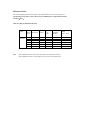
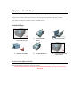
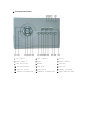
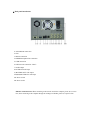
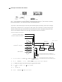
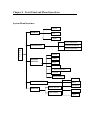
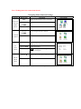
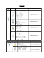
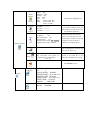
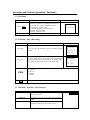
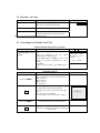
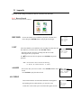
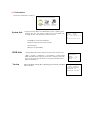
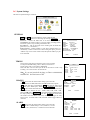
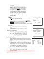
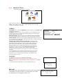
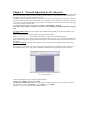
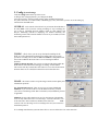
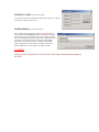
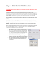
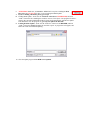
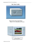
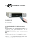
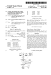
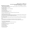
DVR-0414 Digital Video Recorder
Operation Manual
IMPORTANT SAFETY INSTRUCTIONS
•
•
•
•
•
•
•
Keep away from extremely hot places
Avoid direct sunshine
Keep away from humid places
Unit must be horizontally installed
Avoid violent vibrations around the unit
Do not place other devices on top of unit
Keep in well ventilated places, not to block the radiator fan setting in the back of the recorder
INSTALLATION PRECAUTIONS
Please make sure the power selection switch is in the right position to correspond to the power supply. After confirming
the connection of power lines, power the unit on. When powered ON for the first time, ensure the Hard Disk is
installed, and the master-slave jumper switch is set correctly.
TO PREVENT FIRE OR SHOCK HAZARD, DO NOT EXPOSE THIS PRODUCT TO RAIN OR ANY TYPE OF
MOISTURE
INCLUDED WITH YOUR DVR
Your DVR packaging box should contain:
•
One power cable
•
One network connection line and one serial port connection cable
•
One package of installation fittings and screws
•
One operation manual and a Software CD
•
Quality Certification of the product
Chapter 1 Product Features and Specifications
1. Product Specifications
Parameter
Processor
Operation system
Model
Video input
Video output
Audio input
Audio output
Video display
Video standard
System resource
Image resolution
Motion detection
Video compression
Audio compression
Image compression rate
Video recording speed
Image quality
Hard disk
HDD space used
Alarm input
Alarm output
Alarm relay
MODEM connection
Network connection
Pan-tilt control
Power
Power consumption
Working temperature
Working humidity
Barometric pressure
Size
Weight
4 Channel
Trimedia PNX1302/200MH
Real Time Operating System(PSOS)
0414 DVR
4 Channels (NTSC/PAL) BNC(1.0VP- P , 75Ω)
1 Channel PAL/NTSC,BNC(1.0VP- P , 75Ω)video signal
1 Channel 200-1000mv10KΩ(RCA)
1 Channel 2000mv 1KΩ(RCA)
1 or 4 window display
NTSC(525 line, 60f/s),PAL(625 line, 50f/s)
Real-time recording, one channel playback and simultaneous network operation
Real-time monitor 704×576, playback 352×288,
Area setting: 192 detection areas on the screen; detection sensitivity setting: 3 levels detection
sensitivity for each area
MPEG-4 CBR (fixed frame rate); MPEG-4 VBR (variable frame rate)
G.729、ADPCM
352×288CIF format,176×144QCIF format,704×576 4CIF format
Real-time mode: PAL 1frame/10second-25f/s for each channel adjustable; NTSC 1frame/10second30f/s for each channel adjustable
6 levels selectable
2 IDE ports (Internal), 1USB port for additional backup
Audio:14.4Mbyte/hour
Video:60-460Mbyte/hour
4 channel voltage alarm input(+5~+15V D. C. Needed for the alarm input)
3 channels output, (output in open/close contact or controllable +12V output)
30VDC 1A, 125VAC 0.5A(relay output)
Installed, Internal
RJ45 10M/100M Ethernet connection
RS485, RS232
220+25%VAC / 50+2% HZ
60W
-10℃-+55℃
10℅-90℅
86kpa-106kpa
2U standard industrial case,441 (breadth)x430 (depth)x89mm (height)
5KG (Without HDD)
2. Product Features
Real-time Monitor
• Analog Video output port, ability to monitor on a computer display or a TV monitor
•
Single window / 4 windows monitor
Compression Method
Multiple video compression modes: MPEG4 fixed frame、MPEG4 adjustable (variable) frame, single channel or 4
split audio/video real-time recording or multi-channel non-real time audio/video recording
Storage
•
•
•
1-2 IDE-connected large capacity HDD inside (Maximum capacity 200GB per drive)
Alternate HDD working method, reduce the power consumption and heat emission
Overwrite and Stop modes selection when HDD is full
Back-up
•
•
USB port to back up records
Download recordings from DVR to local PC via network or Internet
Play and Record
•
•
•
•
•
•
Support multiplex operation: live monitoring, recording, searching for download, one channel play-back, and
remote transmissions, simultaneously
Multiple recording modes: manual, timed (scheduled), alarm, motion detection
Playback: PIP or multi-channel real-time monitor during playback
Fast search for timed (scheduled) recording and alarm recording
Multiple play-back modes: fast play, pause, X1/2, X1/5 slow play and frame by frame playback
Display the event occurrence time when playing back
Alarm relay
•
•
•
4 channel external alarm input, video lost alarm and motion detection alarm
Multi channel relay switch alarm output (for quick alarm relay and on-spot light control)
Protection circuit for Alarm input and output to assure the safety of the DVR
Pan-Tilt Control
•
•
Support for a pan-tilt decoder using RS485 communication
Able to integrate multiple decoding protocol so as to control various pan-tilt and speed dome cameras
Communication connection port
•
•
•
15-pin port to realize alarm input and pan-tilt lens control
RS232 port for the connection with keyboard for central control and matrix control
Standard Ethernet port for remote monitoring and control
Network operation
•
•
•
•
•
•
•
Remote real-time monitor via network
Pan-tilt control
Records search and real-time playback (playback quality depends on network speed), downloading video
recordings to files
System setting modification and system software upgrading via network connection
Remote alarm process and system log review
Embedded TCP/IP protocol, supports Web server (direct connection through Internet Browser for all of the
above functions)
Administration mode: Multi-level user administration on network; password mode verifies each user
Reference Chart:
The recording length depends on the capacity of the installed HDDs and the selected image level.
The following storage time is based on the average used HDD space for single channel real-time
recording(30f/s)
Audio recording not included in this chart.
Coding
Fixed
Baud rate
Note:
Image
level
1
2
3
4
5
6
Resolution
352*288
352*288
352*288
352*288
352*288
352*288
Frames
25
25
25
25
25
25
TV
Frames
330line
330line
330line
330line
330line
330line
Maximum
data flux
128Kb/S
256Kb/S
384Kb/S
512Kb/S
768Kb/S
1Mb/S
Under adjustable baud rate 1f/10s-25f/s selectable, fit for all kinds of occasions
Under adjustable baud rate, if static images prevail it can save more HDD space.
Average used
HDD
space(/hour
)
40MB
80MB
120MB
160MB
240MB
320MB
Chapter 2 Installation
1. Hard disk installation
Because there is no built-in hard disk in the machine, check the hard disk equipment for the first installation.
Maximum is 2 hard disk drives installed internally. User can decide the capacity of hard disks according to required
image quality, recording time (maximum capacity is 200GB per drive).
Installation Steps
1. Dismantle the fixed
screws of the top cover
4. Install the second HD
2.
Dismantle the HD
Bracket
5. Assemble HD Bracket
3. Install the first HD
6. Close the top cover and
screw it back on
INSTALLATION PRECAUTIONS
Please make sure the power selection switch is in the right position to correspond to the power supply. After confirming
the connection of power lines, power the unit on. When powered ON for the first time, ensure the Hard Disk is
installed, and the master-slave jumper switch is set correctly.
TO PREVENT FIRE OR SHOCK HAZARD, DO NOT EXPOSE THIS PRODUCT TO RAIN OR ANY TYPE OF
MOISTURE
2. Front panel introduction
1. Up / Camera 1
2. Left / Camera 3
3. Cancel
4. Down / Camera 2
5. Enter
6. Right / Camera 4
7. Play last section
8.Recorder
9. Slow play
10. Function assistant
11.Play/pause
12. Fast play
13. Play next section
14.Power switch
15. Channel 1 recording
16. Channel 2 recording light
17. Channel 3 recording light
18. Power indication light
3. Back panel introduction
1: Alarm-RS485 connection
2: Fan
3: RS232 connection
4: MODEM telephone line connection
5: USB connection
6: NET network connection(RJ45)
7: Audio output
8: AUDIO IN audio input
9,10: VEDIO OUT video output
11,12,13,14: VEDIO IN vedio input
15: Power switch
16: Power socket
Ethernet connection note: When connecting to the network card of the computer, please use a reverse
line; when connecting to the computer through an exchanger or Modem, please use a positive line.
Key Functions
Order
Key name
14、19
Power switch
and
indication
light
15、16、17
Logo
POWER
Function
Remarks
Power switch(Power off by pressing the key
for 4 seconds)
Indication light
Recording
When the light is RED, channel is
Red
lights
2、6
Left and
right
1、4
recording
W X
Up and down
TS
Transverse moving, shifting level 1
and level 2 menus; pan-tilt control
shift when monitoring audio/video,
change to channel 3 and channel 4
Lengthways moving; change setup; change
number; pan-tilt control; when monitoring
audio/video change to channel 1 and
channel 2
Cancel
3
Cancel
ESC
During playback of recording, restores to realtime monitor
5
Enter
ENTER
Enter
Enter main menu
During monitoring, switches between
single / four window
10
Function
assistant
Fn
Press the key to display the menu of the pantilt control and camera lens control.
When setting Motion
completes the setting.
Detection
areas,
During playback, displays the playback status
bar
8
Manual start/stop recording,apply
together with number key, shadow
numbers to start recording
RECORD
Rec
Shadow single channel: shadowed
channel real time recording;shadow5,
four channels real time recording.
Shadow multi-channels, shadowed
channels non real time recording 2
channel 12 frame/channel,3 channel 8
frame/channel,4 channel 6
frame/channel
RECORD
1 2 3 4
SELECT
CHANNEL
7
9
Play Previous
Slow play
►
Play/pause
f/
Play the file recorded previously to the one
playing at the moment
3
Speeds
of
slow
speed(×1/2、×1/5、×1/25)
play
Play/pause
11
12
Fast play
13
Play Next
When monitoring, press to enter Recording
Search menu
Different speeds of fast play speed
Play the next recorded file
4.1 Serial port connection and extension
Note: ① The connection for program upgrading or debugging through serial port ②The connection for dial-up
login through MODEM ③ The connection for DVR control through keyboard
If you want to control P/T/Z and process the relay of the alarm-IN signals by the DVR, you have to do so through
the alarm relay connection (the 15 pin plug at the back panel.) This connection can control various pan-tilt
decoders, and the specific type of the decoder can be selected from the Control of the System setting in the menu.
The foot’s serial number is marked on the DB15 plug. The definition of the foot is as follows.
ALARM OUT 1 NORMAL CLOSE CONTACT
ALARM OUT 1 COMMON TERMINAL
A LARM OUT 1 NORMAL OPEN CONTACT
1
ALARM INPUT ALARM IN 4
┆
┆
┆
ALARM INPUT ALARM IN 1
6
7
2
RS485 B Line
12
3
8
13
3
9
14
3
4
10
GROUND LINE
120Ω resistance
RS485 A Line
11
5
B
A
B
Decoder
A
Decoder
15
3
Alarm output 3 common terminal ALARM OUT 3_C
Alarm output 3 common open contact ALARM OUT 3_NO
+12V output
Alarm output 2 common terminal ALARM OUT 3_C
Alarm output 2 common open contact ALARM OUT 3_NO
a)
1,2,3,4 connects to ALARM IN 1~ALARM IN 4;
b)
6,7,8 – ALARM OUT
c)
15 +12V power output, can be used as the power supply for alarm sensors;
d)
11 - A line of RS485 ,12 - B line of RS485 ;
e)
5 - Ground line
f)
13\14 – ALARM OUT 3 normal open contact
1,9,10 – ALARM OUT 2 two group relay output(digital);
Connection of the alarm input:
Short connect between the alarm input end and the
power(infrared sensor for example)
Connection terminal of the alarm device
GND
+12V
Com
NO
◎
◎
◎
◎
◎ALARM IN 1_2
┇
Alarm input port
◎ALARM IN 1_1
◎+12V
◎GND
Alarm input end:
4 channels of alarm inputs, no limits on the input type (normally open or normally close type). The power of the alarm
sensors can be provided by the DVR (Note: If the DVR provides power to too many alarm sensors, it may affect the
normal working of the DVR.).
Note: When the alarm sensor is powered by external supply, the ground line must be connected with that of the alarm
output port of the DVR.
Alarm output end:
3 channels for alarm outputs (normally open contact). In order to avoid overloading the DVR, please refer to the related
parameter of the relay, and see the attached form for the related relays’ parameter.
RS485 (A/B lines):
Used to connect the A and B line of the pan-tilt decoder
Model sketch of the alarm input end:
Model sketch of the alarm output end:
Parameters of the alarm output relay:
Model: G6H
Contact Material
Rating(resistance load)
Insulation
Surge voltage
Length of open time
Length of close time
Temperature
Silver
30VDC 1A, 125VAC 0.5A
62.5VA 33W
125VAC, 110VDC
1A
750VAC 1minute 50/60Hz
1000VAC 1minute 50/60Hz
1000VAC 1minute 50/60Hz
1500V (10×160us)
3ms max
3ms max
-40~+70℃
Rated switch capacity
Maximum switch power
Maximum switch voltage
Maximum switch currency
between touches with same polarity
between touches with different polarity
between touch and winding
between touches with same polarity
Chapter 3: Quick-Start (Turning the DVR ON for the First Time)
Before starting the machine, make sure that a Hard Drive has been installed and all the lines are
connected correctly (refer to Chapter 2 for more information).
Start the DVR:
Plug the power line in; switch power button at the back of the recorder to ON; power indicator will light
on; DVR is starting.
The default four windows for the video output will appear on the monitor.
If the DVR was turned on during the set “Timed Recording” times, recording will start automatically.
To change the “Timed Recording” settings, go into Menu -> System Setting -> Timing.
Default “Timed Recording” is preset to 00:00 AM – 00:00 AM; ON (recording 24 hours a day).
Enter the Settings menu
Press Enter (password prompt will appear)
There are two levels of password (Guest, and Manager). At this point you need to enter the Manager
password.
Default password is “555555”. To enter this password press the “Play Next” button () 6 times.
For security reasons, we recommend you change the password.
To change the Manager password go to Menu -> Admin Settings -> Password
In the “Manage” field, enter your Manager password (any combination of the Playback Control buttons).
Press Enter
Enter this password again in the “Confirm” field.
Press Enter twice.
MAKE SURE TO REMEMBER THIS PASSWORD!
Power Blackout Recovery:
When the power is cut off during the DVR’s operation, the DVR will preserve the recorded
information and settings. When the power is back online, the unit will power itself up and continue
recording. To avoid Hard Disk failures, and for security reasons, we recommend the DVR to be
connected through a UPS (Uninterruptible Power Supply) device.
Recording Operations
The default recording mode of the DVR is 24-hour continuous recording; but it is also possible to change this setting.
The 0414 DVR supports four recording modes..
To change Recording Modes:
A) Timed Recording:
To change the “Timed Recording” settings, go into Menu -> System Setting -> Timing.
Default “Timed Recording” is preset to 00:00 AM – 00:00 AM; ON (recording 24 hours a day).
Navigate the different settings using the Left and Right buttons. To change values, use the Up and Down buttons, and
set the recording times for each day.
B) Manual Recording:
Press “Record” on the front panel. A recording menu will appear on the screen, with channels 1,2,3,4. The channels
that are highlighted are the ones that will be recorded. To toggle channel recording, use the Playback Control buttons
on the front panel.
The buttons are listed here, starting from the first button to the LEFT.
Use “Previous Play” button as Channel 1, Use “Play” button as Channel 2, Use “Slow Play” button as Channel 3, Use
“Fast Play” button as Channel 4. Press Enter to begin recording
If you wish to reset the settings to what they were before, press the “Esc” button.
C) Alarm - Triggered Recording:
Connect the alarm input according to the device connections instructions in Chapter 2
To setup the alarm recording, go to: Menu -> System Setting -> Alarm
Select the wanted variables for each channel.
To save your settings, press Enter twice, press Esc twice to exit menu and return to monitoring.
D) Motion Detection - Triggered Recording:
Before using motion detection on any channel, you should disable the Timed Recording settings for that channel.
To start setting up the motion detection, go to: Menu -> System Setting -> Motion Detection. Set the proper motion
detect settings for each channel. To set up the Detection Area, navigate your cursor to “Area” and then to “Set”, press
Enter.
After changing settings to motion detection (turning it on/off as well), you must manually shut down the
recording on the channels you wish to record by motion. The DVR will turn the channels back on when it
detects motion.
3. Alarm Trigger
The 0414 can trigger an external alarm system when either motion is detected or video is lost (any problem with the
camera, recording, wires, or vandalism will be considered by the unit is “Video Loss”, and can trigger an alarm).
Connect the alarm input according to the device connection instructions in Chapter 2.
Connect the related alarm output to the proper Alarm Out ports on the DVR (see chapter 2 for details).
4. Pan-Tilt Control
The 0414 supports Tan-Tilt control (PTZ) through the RS232 port on the back of the unit. To enable this control,
connect your decoder to this port, and respectively to the PTZ device. Please make sure the decoder is
properly wired (confirm the right connection of the decoder’s A/B lines and DVR’s 15-pin port’s A/B lines
– see chapter 2 for more details).
You then need to setup the protocols and other control settings by going into Menu -> System Setting -> Control
In order to control the PTZ camera, switch to Single-Window view of the camera (by pressing the corresponding
“Direction” button).
When in single-window view, use the direction buttons to move the camera around.
Network Connection Operation
You can install software updates, download recordings, modify settings, and control a Pan-Tilt camera and the DVR
through TCP (network or the Internet remote connection)
To establish a TCP-IP connection, please make sure the LAN connector on the back of the unit is properly wired to the
computer or router. You will need to setup the DVR’s server IP address, subnet mask and gateway, prior to connecting
to it. If there is no router on the network, you only need to set the IP address. If there are routers on the network, please
set the proper gateway and subnet mask.
To setup the network properties for the DVR, go to Menu -> System Setting -> Network.
Please make sure the DVR’s IP is unique on your network. We recommend restarting the DVR after setting up
its IP.
To test if the DVR is online: On your computer, open Command Prompt (usually in the Accessories folder in your
start menu).
When command prompt opens, type the following (without the quote marks):
“PING ***.***.***.***”
(the * stands for the numbers you chose to be the DVR’s IP address)
If your ping response is successful, you will get a reply from the DVR. If it is not, a “Request timed out” message will
appear (if this message appears, please double-check all proper connections and settings, restart the DVR, and try the
PING again).
To connect to the DVR: Open your Internet Explorer browser. Input the DVR’s IP address into the Address field,
press Enter.
Click the “Login” button on the top-left side of the loaded page.
Default login is “admin” and password is “admin”.
It is important to change this password! To change passwords and manage users, click on “Assistant” on the topright of the screen, choose “User Manage”. Click “Admin”. Click “Modify”. You may now enter a new password.
Click “OK” then “Save”.
Chapter 4 Front Panel and Menu Operations
System Menu Structure:
Record
SEARCH
List
Alarm
System Information
Hdd State Information
INFOMATION
Version Information
M
E
N
U
General
SYSTEM
SETTING
Timing
Image
Alarm
Control (for Pan-tilt)
Network
Motion detection
Password
ADMIN SETTING
BACKUP
Others
Backup Records
Data Delete
Default
Delete Backup
Logout
Note: Flashing item is the current item selected.
Navigating Menu Items and Settings
Operation
Button Order
Enter
Description
Screen display
During real-time monitor, press to open menu
Enter main
menu and
Direction
level 1
STXW
submenu
Enter
Direction
Press to select one of the icons
Enter the selected level 1 submenu
Press to navigate the level 2 submenu
SEAVRCH
STXW
Enter level
2 submenu
Enter
Direction X
Set
menu
contents
Select the option you want to change (option
flashing when selected)
Direction ST
Enter
Change setting value
Save is flashing; Press Enter again to save the
settings you changed. *
Direction W
Exit the
current
menu
Enter the selected level 2 submenu
ESC
Return to the previous option of the current menu
CH
1
PROTOCOL NONE
BAUDRATE 4800
ADDR
SAVE
000
CANCEL
SEARCH
Exit to the last level menu / Cancel
* You can perform setting changes to multiple channels before exiting menu, and save the settings altogether.
Menu Options
Main
menu
Menu level 2
Menu level 1
GENERAL
SYSTEM
SETTING
TIMING
IMAGE
ALARM
DATA
07-22-2003
FORMAT
16-11-2 0 0 3
TIME
18:18:18AM
FORMAT
AM/PM
SAVE
SAVETIME
HDDFULL OVERWRITE
RECORDLEN 60 MIN
REMOTEADDR 008
COMMCTRL
DONE
SAVE CANCEL
CH
1
WEEK
SMTWTFS
TIME1 00:00-24:00
STATE
ON
TIME2 00:00-24:00
STATE
OFF
SAVE CANCEL
CH
1
MODE
CBR
FRAMERATE REAL
BITRATE
1024K
ALARM
OFF
SAVE CANCEL
CH
1
TYPE
NO
RECORD 1234
ALMOUT 123
ADDR
008
DELAY 60 SEC
TIME1 00:00-24:00 OFF
TIME2 00:00-24:00 OFF
SAVE
Main menu
SYSTEM
SETTING
Menu level 1
Pan-tilt
control
Network
setting
Remarks
See details on Appendix 2.6.3
See details on Appendix 2.6.3
See details on Appendix 2.6.3
See details on Appendix 2.6.3
CANCEL
Menu level 2
CH
1
PROTOCOL NONE
BAUDRATE 4800
ADDR
000
SAVE CANCEL
IP
192.168.000.58
SUBNETMASK 255.255.255.000
GATEMAY
192.168.000.001
NONITOR
MULTICAST
PLAYBACK
MULFICAST
SAVE CANCEL
Remarks
See details on Appendix 2.6.3
See details on Appendix 2.6.3
Motion
detection
Password
Others
ADMIN SETTING
Data delete
Default
CH
1
STATE
OFF
TIMEING 30SEC
ALMOUT OFF
SENS
MID
AREA
SET
TIME1
12:00A-12:00A OFF
TIME2
12:00A-12:00A OFF
SAVE CANCEL
GUEST
******
CONFIRM * * * * * *
MANAGE * * * * * *
CONFIRM * * * * * *
See details on Appendix 2.6.3
If you used the Manager Password to
login (Chapter 2) you can change it here.
See details on chart 2.6.4
PLAYMODE
AUDIO SYNC
ALARM TIP
OFF
SHUT PASSWORD
OFF
MONITOR OSD
ON
MAINTENANCE WEEK S M T W T F S
MAINTENANCE TIME 02:00AM
PASSWORD - - - - - -
ARE YOU SURE YOU WANT
LOAD DEFAULT CONFIGURES?
YES NO
During Maintenance Time, unit will
reboot for 6 seconds, then go back to
normal operation. Set this to a time when
recording is not critical. Reboot is
needed to prevent HDD problems.
Input the administrator’s password, then
select to delete data or not
TO
Confirm if you would like to reset
configuration to default factory settings
Logout
Press ENTER to logout
Backup data
BACKUP
Delete backup
DEVICE
USB
CH
1
BACKUP SPEED NORMAL
STARTING DATE 08-21-2003-8-21
STARTING TIME 09:02AM
ENDING DATE
08-21-2003-8-21
ENDING TIME 09:02AM
BACKUP
ADD START
DEVICE USB
DELETE CONFIRM
Recording and Playback Operations: Summary
2.1 Recording
Button Order
Description
Display
Manual start/stop recording,apply together with
number key (see chapter 3). Highlighted channels will
record. If only one channel is highlighted, it will be
recorded at REAL TIME (30 FPS);
If 2 channels highlighted: 12 frames/channel
3 channels: 8 frames/channel
4 channels: 6 frames/channel
Press to save the settings and continue
Record REC
Enter
RECORD
1234
SELECT CHANNEL
2.2 Playback: Play a Recording
Key Order
Description
Play/pause
Press to open the “Record Search” menu (to playback recorded
records).
Play/pause
Direction
STXW
Fn
Display
RECORD SEARCH
CH
1
DATA
2002-12-08
TIME
09:10
SEARCH START
Press again to begin playback (the screen will show channel,
date, time). If near “Start” it says “NOREC” that means that there
is no record found that matches the date/time you entered. When
the recording finished playing, the DVR will display “End”.
RECORD SEARCH
CH
1
DATA
2002-08-08
TIME
09:10
START NOREC
Used during playback to toggle between cameras.
S Camera 1
T Camera 2
W Camera 3
X Camera 4
During playback, this button shows / hides the live monitoring frame on the right.
2.3 Playback: Fast Play / Fast Forward
Button Order
Description
Fast play During playback, press this key to shift between 2X
speed, and 4X speed
Play/Pause
Press this key to pause; press again to play at normal
speed.
Play Next, Play Previous
During playback, Press to view the next or
previous recording of the channel being viewed.
Display
01 REC
25F/S
2.4 Playback: Slow Play
Button Order
Slow play ►
Description
During playback, press to toggle between:
25f/s, 15f/s, 1f/s speeds and to pause.
Play/Pause
Press to pause the recording / continue the recording
Play Next, Play Previous
During playback, Press to view the next or
previous recording of the channel being viewed.
Display
01
REC
25F/S
Note: 1f/s speed shows the recording frame by frame.
2.5 Controlling Pan-Tilt and Lens (P/T/Z)
Button Order
Enter (Open Menu), then go
to “System Settings” and into
“Control”
Button Order
Setup of the Pan-Tilt and Lens Controller
Description
Select the Channel you installed the PTZ camera
onto.
Choose the Protocol to use (see camera
documentation or ask your dealer).
Set the Baud rate and Address to that of the
decoder (see decoder documentation for correct
values).
Press Enter.
“SAVE” will start flashing. Press Enter again to
save.
Controlling the PTZ
Description
Direction STW X
Select the camera you wish to control and go to
single channel view. To select your camera, press:
S for Camera 1
T for Camera 2
W for Camera 3
X for Camera 4
Fn
Press this button to open Function Assistant.
You will get two options “Pan Control” and “Image
Set”
Select Pan Control, press Enter.
A screen similar to the one on the right will appear.
Direction STW X
Use the direction buttons to control Pan-Tilt
Fn
Press this button again to toggle between PT
Control, Lens Control, Zoom, Focus, Iris, and Light
Control (on/off).
Press Fn to display
CH
1
PROTOCOL NONE
BAUDRATE 4800
ADDR
000
SAVE
CANCEL
Display
PT CONTROL
S
W DIRECTION X
T
2.1 Appendix
Please note: all the settings described below must be saved before they take effect.
2.6.1 Record Search
The menu for record search is as follows:
RECORD
LIST
RECORD SEARCH
Choose the Channel you would like to playback (enter date and
time), then press ENTER TWICE. The playback will begin.
Select the Channel you would like to list recordings for. Then enter the
date and time you wish to locate. Press ENTER TWICE.
The DVR will show all of the recording files that were made
following the time you specified.
RECORD
CH
DATE
TIME
PLAY
1
06-08-2002
18:18AM
START
LIST SEARCH
CH
1
DATE 06-08-2002
TEME 18:18 AM
LIST SEARCH
Use ST to select the file to be played. Press ENTER to begin the
playback.
Note:the letters before the record mean the following:
R—Record;M—Motion detection;A—Alarm
ALARM
First set the date you wish to search. Press ENTER TWICE. Press ST
select the
ALARMto SEARCH
record.
Press ENTER to play the alarm record.
DATE 06-08-2002
SEARCH START
ALL HDDS
This search method is used when data turbulence has happened.
By inputting the exact date and time, you can retrieve the
records lost or the records you can not find with regular searches.
ALL
HDDS
SEARCH
CH 1
DATA 06-08-2002
TIME 18:18AM
PLAY START
2.6.2 Information
The menu for Information is as follows:
INFO
System Info
SYSTEM
Displays how many HDDs are installed, HDD capacity, remaining space,
recording start time (the earliest recording time on the HDDs) and
recording end time. This information is only for reference.
HDD NUM
01
HDD CAP
0083886M
FREE SPACE
0040832M
FILE
START 06-10-2003 00:36
PM
FILE END 06-10-2003 02:28 PM
Press Enter to view bit rate information:
Display the frame rate of the current channels:
Frame rate (Kb/s)
HDD space occupied (MB/h)
HDD State
Displays HDD index and the conditions of master drive and slave drive.
Note: √ = normal, × = malfunction, -- = not installed, √ = current working
HDD. If the HDD in the system goes out of order, a window warning will
pop up on the screen every half an hour. To change the bad HDD, turn to
chapter 2 (Installation).
Version
Shows the DVR issuing date, Operating System Version, and Web
Server Version.
HDD STATE
INDEX
1 2
MASTER ― W
SLAVE ― R
VERSION INFORMATION
VERSION ID 1.00
ISSUE DATE 07-29-2003
2.6.3 System Settings
The menu for System Settings is as follows:
SYSTEM SETTINGS
GENERAL
DATE and TIME are used to modify the current system date and
time; after the modification save the change by selecting SAVETIME;
HDDFULL – instruct the DVR what to do when the HDD is full.
OVERWRITE will tell the system to overwrite existing recordings; STOP
will tell the system to stop recording when HDD is full.
RECORDLEN – will set the length of the recording files the DVR will
generate (15, 30, or 60 minutes).
REMOTEADDR – Remote Address is used when multiple DVR’s are
controlled by a remote control board. When setting this option, press the
“Address” key on the remote control board, and input the address you just
set for this DVR.
GENERAL
DATE
2004-12-01
FORMAT
0 6-1 1-2 00 3
TIME
18:00 AM
FORMAT
AM/PM
SAVE
SAVETIME
HDDFULL
OVERWRITE
RECORDLEN 60 MIN
REMOTEADDR 008
SAVE
CANCEL
TIMING
This is used to setup times for the DVR to start or stop recording.
To setup the Timed Recording, select a channel you wish to set.
The day of the week you are setting is highlighted.
Time1 and Time 2 are two times you can set for the DVR to record or stop
recording. ON = Record OFF = Do Not Record.
Note:If you need record all day long, set Time1 as 00:00-00:00,
and State ON. Set Time2 state to OFF
TIMING
CH
1
WEEK
SMTWTFS
TIME1
00:00 – 12:00
STATE
ON
TIME2
00:00 – 12:00
STATE
OFF
SAVE
IMAGES
In CH option select the channel whose settings you wish to edit.
In MODE there are CBR (audio/video) and VBR (audio/video) options.
AV is audio and video synchronization, Video will make the DVR record
only video (saves HDD space). When in CBR, Framerate is Real time,
Bitrate is the related maximum data flux. You can use the direction keys
STto select the different bit rate.:1024K, 768K, 512K, 256K, 128K.
When in VBR mode, Image quality is selectable between 6 different levels,
the image quality of the sixth level is the best. ALARM ON means alarm
will sound if the DVR detects video loss, and will also trigger the relay
device (port1). If Alarm mode is OFF, the DVR will not trigger alarms on
video loss.
ALARM
In CH option select the channel whose settings you wish to edit.
TYPE will have a default setting to “NO” (normal on). You can
set this to “NC” (normal close) – Normal Close is the Electronic
CANCEL
IMAGES
CH
1
MODE
CBR
FRAMERATE REAL
BITRATE
1024K
ALARM
OFF
SAVE
CANCEL
ALARM
CH
1
TYPE
NO
RECORD
1234
ALMOUT
123
ADDR
008
DELAY
60 SEC
TIME1
00:00 – 24:00 OFF
TIME2
00:00 – 24:00 OFF
SAVE
CANCEL
Output Method.
If the number in RECORD is selected, recording will start
automatically when the DVR senses an alarm trigger input.
ALMOUT – Alarm Output. If the alarm output port is chosen,
it will trigger any connected equipment (on the chosen port)
when there is alarm input. DELAY is the length of recording
time after receiving an alarm trigger (possible settings of 10, 20,
30… 90 seconds). When the external alarm is canceled, the
system will lengthen the recording time automatically before
closing alarm and relay outputs. When Time 1 and Time 2 are
set to ON, the DVR will record during the set time ONLY if
triggered by an alarm. The beginning time should be earlier
than the ending time; the time set in Time 2 should be later than
the setting in Time 1.
CONTROL
This is the P/T/Z Control settings of this DVR.
In CH option select the channel whose settings you wish to edit, and on which a
PTZ camera is installed.
Choose the protocol of the corresponding pan-tilt decoder in PROTOCOL.
ADDR is the address of the corresponding platform decoder.
BAUDRATE select baud rate of the corresponding decoder.
SAVE your settings, and you can now control your cameras. (Note: If controlling
multiple PTZ cameras, you must use a PTZ Decoder-Splitter)
CONTROL
CH
1
PROTOCOL NONE
BAUDRATE 4800
ADDR
000
SAVE
CANCEL
NETWORK
This is the setup of remote Network (TCP) connections to the
DVR.
For details on how to set the DVR on the network, go to Page 17
(Network Operations).
Playback Options Description:
MULTICAST: “Manager” users can monitor each channel
freely, and other users can only view after
them. Maximum of 5 users.
TCP Protocol: Any user can monitor any channel. If the
transmission is via Internet, TCP should be
chosen. Maximum of 2 users.
NETWORK
IP
192.168.000.111
SUBNETMASK 255.255.255.000
GATEWAY
192.168.000.001
NONITOR
MULTICAST
PLAYBACK
MULFICAST
SAVE
CANCEL
MOTION DETECTION
CH - Choose the channel you wish to edit.
MOTION DETECTION
TIMING – The amount of time the DVR will wait before triggering the alarm.
CH
1
ALMOUT – (Alarm out) this sets the external alarm trigger by the DVR on/off.
TIMING
30 SEC
SENS – Sensitivity will determine how sensitive the DVR will be to motion.
ALMOUT
OFF
AREA – Navigate to ‘SET’ and press Enter, this will set up the masked / nonSENS
MID
AREA
SET
masked areas (masked areas will not respond to motion, non-masked will be
TIME 1
12:00A-12:00A
monitored for motion). The setting area can be divided in 396 sections. Red
OFF
section means the current cursor position, and green section is the motion
TIME 2
12:00A-12:00A
OFF
detection area. The no color area is masked from motion detection. To mask /
unmask areas, press the Fn button. Then use the Direction
buttons to move cursor around the grid. Any grid-square you
move over will be masked from motion detection. Press Fn
again to set the area. For un-masking areas, do the same.
TIME 1 – Between the times you set, the DVR will record and
monitor motion (if set to ON)
Time 2 – You can set two different times of the day when the
DVR will monitor motion.
After changing settings to motion detection (turning it on/off as well), you must manually shut down the
recording on the channels you wish to record by motion. The DVR will update the settings, and turn the
channels back on when it detects motion.
2.6.4
ADMIN SETTINGS
The menu for System Settings is as follows:
ADMIN SETTINGS
Select “Password” and press Enter to change passwords. Guest users have
limited control abilities on the DVR, whereas Manager users can fully
control/erase/change data on the DVR.
OTHERS
PLAYMODE – has two modes, VIDEO BEST (the best video flow) and AUDIO SYNC
(the best synchronization.)
ALARM TIP – When this option is ON, the DVR will act as an Alarm-Thru (when
receiving a trigger from an external alarm, the DVR will send out the same trigger
through its alarm-out ports as well).
SHUT PASSWORD – When this option is ON, the DVR will ask for the “Manager”
User password when turning off; if password is incorrect, the DVR will not shut off.
MONITOR OSD – When set to ON, this function will display the Date, Time, and Cam
No. on the monitors (turn this option to OFF when playing back an existing recording, to
avoid “Time-over-Time” displaying).
MAINTENANCE WEEK / MAINTENANCE TIME – This function must
be enabled on all DVR’s. This is an important function, and is needed to avoid
HDD failures, resets the Web-Server to protect against exploits and hackers,
clears caches for faster performance, and sets the password prompt back on.
During maintenance time, the DVR will perform all of these functions and
then restart itself. This means that the recording will be OFF for about 15
seconds. We recommend setting this option to a time of the day when
recording can be interrupted for a few seconds, such as when a security guard
is present.
To set the maintenance time, highlight the “Maintenance Week” day you wish
to set, and then set the time. You can set all days to their maintenance time,
and then save once – this will save all of the settings. The highlighted days
are the ones that are set to ON.
PLAYMODE
AUDIO SYNC
ALARM TIP
OFF
SHUT PASSWORD
OFF
MONITOR OSD
ON
MAINTENANCE WEEK S M T W T F S
MAINTENANCE TIME 02:00AM
DATA DEL
This function lets you erase all recorded data from the HDD.
CAUTION: DATA THAT WAS DELETED CAN NOT BE RECOVERED!
Before the DVR will let you delete the HDD, you will be prompted for the “Manager”
password.
A confirmation screen will then appear. To clear the HDD, choose “yes”.
PASSWORD
------
ARE YOU SURE YOU WANT
TO DELETE FILES?
YES
NO
DEFAULT
This function will set all configuration of the DVR to the factory default
configuration. To do this, navigate over to this function, press Enter.
A Confirmation screen will appear. Choose “Yes”.
ARE YOU SURE YOU WANT TO
LOAD DEFAULT CONFIGURES?
YES
NO
LOGOUT
This will log the user out, and next time the user wishes to access
the menu, they will need to enter the password again. This must be
done every time in order to avoid others meddling with
configurations of the DVR, or disabling it.
Navigate over the function, press Enter, and then confirm log-out.
2.6.5 BACKUP
BACKUP DATA
DEVICE – chooses the backup device the DVR will use.
CH – chooses which channel to back-up.
BACKUP SPEED – chooses the backup speed the DVR will use.
STARTING TIME – will back up all clips after this date (inclusive).
STARTING TIME – will backup all clips after this time (inclusive).
ENDING DATE – will backup all clips UP-TO this date (inclusive).
BACKUP – choose “Start” to start backup. The DVR will show a progress
indicator box on the monitor. If the device is not connected, or if there is a
problem with the connection the DVR will display “NO BACKUP DEV”.
If the backup device is full, the DVR will indicate the volume of the device is full.
During the backup operation, the DVR will display the time remaining for
backup.
BACKUP DELETE
Will clear the backup device connected to the DVR, and erase all information on it.
REVICE
CH
BACKUP SPEED
STARTING DATE
STARTING TIME
ENDING DATE
BACKUP
USB
1
NORMAIL
08-21-2003-8-21
09:02AM
08-21-2003-8-21
ADD
START
Chapter 5 Network Operation (LAN / Internet)
The 0414 DVR does not need any client software (although client software can be used, and is included with the DVR)
You can install software updates, download recordings, modify settings, and control a Pan-Tilt camera and the DVR
through TCP (network or the Internet remote connection)
To establish a TCP-IP connection, please make sure the LAN connector on the back of the unit is properly wired to the
computer or router. You will need to setup the DVR’s server IP address, subnet mask and gateway, prior to connecting
to it. If there is no router on the network, you only need to set the IP address. If there are routers on the network, please
set the proper gateway and subnet mask.
To setup the network properties for the DVR, go to Menu -> System Setting -> Network.
Please make sure the DVR’s IP is unique on your network. We recommend restarting the DVR after setting up
its IP.
To test if the DVR is online: On your computer, open Command Prompt (usually in the Accessories folder in your
start menu).
When command prompt opens, type the following (without the quote marks):
“PING ***.***.***.***”
(the * stands for the numbers you chose to be the DVR’s IP address)
If your ping response is successful, you will get a reply from the DVR. If it is not, a “Request timed out” message will
appear (if this message appears, please double-check all proper connections and settings, restart the DVR, and try the
PING again).
To connect to the DVR: Open your Internet Explorer browser. Input the DVR’s IP address into the Address field,
press Enter.
The first time you visit the DVR, the system will pop up the dialogue box to ask whether you accept ActiveX or not.
You should then choose “Yes”. The system will install the control automatically, and Web interface will appear.
6-1 – The Web Interface
Click the “Login” button on the top-left side of the loaded page.
Default login is “admin” and password is “admin”.
It is important to change this password! To change passwords and manage users, click on “Assistant” on the topright of the screen, choose “User Manage”. Click “Admin”. Click “Modify”.
You may now enter a new password. Click “OK” then “Save”.
The interface will have a menu of buttons on the top.
Options are 1) Login 2) Logout 3) Search 4) Config 5) Assistant.
If after the input of the username and password, the following box pops up;
system is warning that some other user has used this name and logged in. Please
use another name to log in.
If after the input of the username and password, the following message appears (6-4), it means that the username or
password were not entered correctly. Please make sure the “CAPS LOCK” button is off on your keyboard (if your
username and password have lower-case letters) and try again.
6-4 – Password Error Message
2. Log out
Use this function to log yourself out of the DVR (stop monitoring). If
you forget to log out, the DVR will automatically time-out the user after
some period of inactivity (30 minutes). When logging out, a
confirmation dialogue box will appear.
3. Operating the Right-Click Menus
After you log in as Administrator, the. Click the right button on your mouse, and the following menu will show:
The Right-Click menu includes: Real time monitor, Playback control bar, Pan-tilt control, Set volume, Net data
flux, Full-screen, Resize video... These options will not be discussed in detail.
REAL TIME MONITOR – lets you select which channel you would like to display full screen.
PLAYBACK CONTROL BAR – lets you open a window to playback recordings.
PAN-TILT CONTROL – lets you control and move the p/t/z camera (if installed). Note that before you can
control a PTZ camera, you must set it up on the DVR itself.
SET VOLUME – controls the audio volume, or mute the sound.
NET DATA FLUX – will show the amount of data transmitted by the DVR over the
network. When no network data was transmitted, the statistics shows zero.
FULL SCREEN – there are two ways to monitor the DVR: regular console or full
screen. You can choose between the modes by either double-clicking the window
directly, or by choosing this option in the menu. During multi-channel monitoring, you can choose any
channel to display full-screen by double-clicking on it.
Resize Video / Zoom – it is possible to make the monitoring window larger or smaller. Smaller window
will display at higher resolution, with a clearer image. If monitoring more then one channel, each channel
can be adjusted.
4. Video – pops up the same menu as Right-Clicking on the screen will.
5. Records Search
Click on the Search button on the top, a dialogue will popup that looks like this:
Input the recording time, channel number and searching type (Record or Alarm), then click “Search”.
The results will show up. The window will only show 15 records at a time. To view more records, click the
“Page Up” and “Page Down” buttons.
Double click the record you want to play, and the DVR will play the selected record.
Records can be played at full screen.
Save record stop save capture picture
full screen
During the playback, you can operate by the buttons in the playback bar like save record, stop save, capture
picture, fast play, pause, full screen. During the playback on the video screen it shows the channel number,
time and data flux of the record.
You can also download the records onto your computer for later viewing. To do this, you can either choose
“Save Record” from the playback menu (record will automatically be saved into C:\Downloads on your
computer).
Or, you can use the Download function in the Records Search dialogue box.
It is possible to download more then one record at a time. Simply select the records you wish to download,
and click “Download”. Records will be automatically saved into C:\Downloads on your computer.
When a record is saved onto your computer, the DVR will give it a name. The name format is as follows:
File name + channel number + date + time.mp4
File extension will always be “*.mp4”.
Example: a-0120021205071028.mp4, 01 means channel 1, 20021205 means December 5th of 2002,
071028 means 7 o’clock 10 minutes 28 seconds.
After clicking the “Download” button, a dialogue box will appear that will let you name the clip you are
about to save. Input the file name and choose Save.
The screen shows the processing of the downloading until the completion:
5. Config (System Settings)
Click the Config button on the top of the screen.
A dialogue box will popup that lets you configure the DVR.
Your options will be: General, Timing, Image, Alarm, and Motion Detection.
If a part of the menu (or a whole menu) is disabled (gray color), that means you have to set the setting up
LOCALLY on the DVR itself.
GENERAL – main controls of the DVR. Lets you instruct the DVR what to
do when HDD is full (overwrite existing recordings or stop recording), the
way a PTZ is controlled (protocol, address, baud) for each channel, and
Recycle Monitoring (instead of displaying one channel constantly, the
monitoring console will switch the channel viewed every X-seconds (set in the
Interval drop-down box).
TIMING – this is where you can set up the timed recording for the
DVR. As well as timed motion detection recording. There are two time
periods for recording. The set time in Time 1 and Time 2 is independent with
the set time in Motion detection. There is no week setting for Motion
detection.
Timing of motion detection: User can set two time periods during which the
DVR will use motion detection (and trigger recording / external alarm).
The set time will only be taken into effect when it is set to ON. If both motion
detection times are set to OFF, the DVR will not use motion detection.
IMAGE – this menu is used to set up the image-controls such as quality and
transmission protocols.
Net Transmission Protocol - There are two types of protocol: TCP and
Multicast. If you want to be able to visit the DVR via internet, you must
select TCP; if monitoring will be done via Intranet (LAN) a Multicast protocol
is applicable.
Multicast: the user with control power can view the image at will and other
users can only follow this user to view the image. 5 users are allowed to view
at the same time. Able to monitor 4 channels at the same time.
TCP:
each user can view the image at will. According to the need, user can choose
the different protocol.
If it is through outer Ethernet you must choose TCP. 2 users are allowed to view at the same time.
Style - there are two options for video encoding, and they are VBR (Variable Baud Rate) and CBR
(Consistent Baud Rate). For VBR, the higher the level number (1 – 6) the better the quality of video.
For CBR, you can choose different frame-rates.
VBR Image Level
Level 1
Level 2
Level 3
Level 4
Level 5
Level 6
Data Flux (Kb / S)
128
256
384
512
768
1000
ALARM – when there is an alarm connected to the DVR, this menu lets
you select the output ports and channels the DVR will record, depending on
the alarm trigger received by the DVR’s alarm-in ports. Selectable for each i/o
port.
MOTION DETECTION - The blue area is the selectable motion
detection area. You can use the cursor to choose the area to be masked or
un-masked. You can also adjust the sensitivity of any area.
Click the “Full Screen” button (or right-click on the area) to display the
motion detection area full screen. After setting the area you can either
Clear (reset to what it was previously) or Save settings.
Alarm output:This instructs the DVR to trigger an alarm-out port, and
lets you select a port. The default setting is Port #2. If you want to use this
channel as a motion detection channel at ALL TIMES, then you have to
turn off any Timed Recording settings for the channel (see TIMING
above).
After changing settings to motion detection (turning it on/off as well), you must
manually shut down the recording on the channels you wish to record by motion.
The DVR will turn the channels back on when it detects motion.
7. Assistant
When clicking on the Assistant button on the top of the screen, you will get the following
options:
User Manage, Record Control, Apply for Control Right, Log Information, System Info,
Channel Name, and Upgrade Bios.
USER MANAGE – will display the user information of the DVR. In here, you can save, add, modify,
and delete users. The DVR supports 3 levels of users:
• Administrator – allows the user to modify user
information, and change DVR settings (this is
the “Manager” user locally).
• User – user can monitor and download
recordings, but can not change DVR settings or
user information.
• Guest – can ONLY modify his/her own
personal information and commence live
monitoring (record searching, system settings,
and all other controls are disabled).
Add a new user: click the “Add” button on the right of the User
Management panel. A dialogue box appears like the one on the
right. Fill out the user information, and select the User Power (this
is the same as the User Level discussed above).
Modify an Existing User: click the “Modify” button on the right of the User Management panel. You will now be
able to modify user details and power.
RECORD CONTROL (assistant menu option)
This option allows you to start and stop recording of any channel.
APPLY FOR CONTROL RIGHT (assistant menu option)
When a user of a lower power level wishes to gain a higher control power, it is
possible through this function. If a user wants to have the control power, the
user has to apply and gain the authorization of the user who already has a
higher control power (such as an Administrator). If the logged-in users are all
normal users, the first logged-in user gains the control power automatically. If
an Administrator logs in later, they can gain the control power by selecting
“Force to apply”. If only one user logs in, or the logged-in user is the user with
control power, the box is disabled.
When a user applies for control power, a dialog box such as this will appear on the superior user’s screen:
LOG INFORMATION – lets you view the system log. With any actions taken by anyone who was logged in.
SYSTEM INFORMATION (assistant menu option)
Lets any user check the basic system information and configuration. You can: control
audio on/off, change Video modes (PAL/NTSC, choose network transmission protocols,
change non-real time recording transmissions (Default is Extract I Frame), and turn Auto
Cycle on/off (when ON, the DVR will switch between the channels automatically while
monitoring).
Net data flux:during real-time monitor it shows the statistics of the network
data transmitted.
CHANNEL NAME (assistant menu option)
Lets you change the name of channels (Default settings is Channel 1, Channel
2, Channel 3, Channel 4; respectively).
UPGRADE BIOS (assistant menu option)
Lets you update the DVR software remotely. (CAUTION! Only use
authentic and official N-Patrol Inc. updates for the DVR software! If
you have any questions about this function, please consult your dealer
before proceeding with an upgrade) To update bios, please make sure to
open the file corresponding to the button you press (Web updates
should ONLY be sent by pressing the “Send Web” button. BIOS
updates should ONLY be sent using the “Send Bios” button; Boot
updates should ONLY be sent using the “Send Boot” button.)
CAUTION!
Incorrect software updates may result in fatal system failure and permanent damage to
the DVR!
Chapter 6 BIOS / Web File UPDATE Over LAN
CAUTION! Incorrect software updates may result in fatal system failure and permanent damage
to the DVR!
At times, N-Patrol Inc. will release updates for the DVR software to increase DVR efficiency,
functionality, and other aspects of the DVR’s operation. These updates are ONLY available through the NPatrol website, or directly from your dealer. When an update is available, and you choose to install it into
the DVR, please use great caution. Please do not accept any updates from anyone that is not an authorized
N-Patrol dealer. Should you have any questions, please contact the person who sold you the DVR.
When updating the system, caution must be taken to differentiate the two different possible system
updates:
BIOS Update – Updates the operating system, functions, security, and other aspects of the DVR’s core
systems. The BIOS is the “brain” of the DVR, and is used to store its Operating System, critical settings,
security information, and other operation-related data.
Web File – Updates the DVR’s Web Client, and compatibility of remote connection through TCP/IP.
Before starting the update, please make sure the DVR is connected to the network, and all network settings
are correct (refer to Chapter 2, Page 17 – “Network Operations” for more details). When all network
connections are established you can now update the DVR.
1.
2.
3.
4.
5.
Run “Upgrade.exe” from the computer you connected to the DVR via LAN.
When the program loads, it will show its interface as follows:
Open the DOS Command Prompt window, and Ping the DVR.
If you are unsure as to how to do this, refer to Chapter 2, Page
17 – “Network Operations”. If Ping was successful and a reply
was received from the DVR, go back to the Update.exe
program, and proceed to the next step.
Click the “CONNECT” button; a dialogue box will appear
where you will need to enter the DVR’s IP. (This is the IP you
set up in the DVR locally, when setting up its network settings.)
Click “Ok” to connect; the program’s status window will now
say “Connect” (this means the computer and the DVR are in
Connect-Mode.)
6.
7.
8.
9.
ATTENTION! Make sure you check the “WEB FILE” box prior to loading the Web
File update and UNCHECK this box if you are loading the BIOS Update!
If you are loading a Web-File, please go to step 9.
Loading BIOS Update – make sure the “Web File” check-box is UNCHECKED, and click
“Load”. Choose the file containing the new Bios version. Click “Open”. The program will show a
progress-bar, and when finished the DVR will restart itself automatically with the new update.
You should now close the program. Or go to step 9 to update the Web File.
Loading Web File Update – make sure the “Web File” check-box is CHECKED, and click
“Load”. Choose the WEBFILE update file, and click “Open”. A progress bar will appear, and
DVR will restart when finished updating.
10. Close the update program. Your DVR is now updated.
Chapter 7 Frequently Asked Questions (FAQ)
1.
When I start the DVR it beeps – what does that mean?
When the machine is powered up and started recording, it will sound a short beep, to confirm that everything is
good.
If the HDD can not be read, or there is a problem with the HDD the DVR will sound a long beep.
If communication with the controller panel is abnormal, or interrupted, the DVR will sound one long beep
followed by two short beeps.
2.
The indicator light is flashing while recording – what does that mean?
When the indicator light is flashing, the DVR is having difficulties with the input signal from the Camera (there is
Video Loss). Check the video connections and wires. If the light is still flashing, the problem then is with the
HDD, and means the HDD read speed is too slow. You will need to change the HDD.
3.
My Hard Drive has bad Clusters/Sectors or was damaged. What do I do?
If the bad sector of the HDD is not too large, the machine would quarantine that sector and ignore it (no recording
will be made to the bad clusters). If a large segment of the Hard Drive is damaged, the machine will shut the HDD
off, and display a warning on the monitor. In this case, it is recommended to change the HDD.
4.
What kind of decoders and controllers can I use with this DVR?
This machine supports and will work with all decoders, and most control board / matrix devices available on the
market.
5.
Can I connect more then one PTZ camera to the DVR?
Yes, the DVR will support PTZ control on all channels. To connect more then one camera as PTZ, you will need
to get a Protocol Decoder Splitter. Ask your dealer for more information.
6.
Can the DVR support a CD-RW?
Yes, the DVR will write onto an external CD-RW, if connected through the machine’s USB port.
7.
I want to operate this DVR off a car / boat battery. How can I do this?
This machine can run off a battery only if you connect it through an external power converter unit.