1
VPort 2141 Video Encoder
User’s Manual
Second Edition, June 2008
www.moxa.com/product
© 2008 Moxa Inc., all rights reserved.
Reproduction without permission is prohibited.
VPort 2141 Video Encoder
User’s Manual
The software described in this manual is furnished under a license agreement and may be used only in
accordance with the terms of that agreement.
Copyright Notice
Copyright © 2008 Moxa Inc.
All rights reserved.
Reproduction without permission is prohibited.
Trademarks
MOXA is a registered trademark of Moxa Inc.
All other trademarks or registered marks in this manual belong to their respective manufacturers.
Disclaimer
Information in this document is subject to change without notice and does not represent a commitment on the
part of Moxa.
Moxa provides this document “as is,” without warranty of any kind, either expressed or implied, including, but
not limited to, its particular purpose. Moxa reserves the right to make improvements and/or changes to this
manual, or to the products and/or the programs described in this manual, at any time.
Information provided in this manual is intended to be accurate and reliable. However, Moxa assumes no
responsibility for its use, or for any infringements on the rights of third parties that may result from its use.
This product might include unintentional technical or typographical errors. Changes are periodically made to the
information herein to correct such errors, and these changes are incorporated into new editions of the publication.
Technical Support Contact Information
www.moxa.com/support
Moxa Americas:
Toll-free: 1-888-669-2872
Tel: +1-714-528-6777
Fax: +1-714-528-6778
Moxa China (Shanghai office):
Toll-free: 800-820-5036
Tel: +86-21-5258-9955
Fax: +86-10-6872-3958
Moxa Europe:
Tel: +49-89-3 70 03 99-0
Fax: +49-89-3 70 03 99-99
Moxa Asia-Pacific:
Tel: +886-2-8919-1230
Fax: +886-2-8919-1231
Before getting started
Before using your VPort 2141, please read the following information.
After opening the VPort 2141 box, compare the contents of the box with the Package Checklist in Chapter
1. Notify your sales representative if any of the items is missing or damaged.
To prevent damage or problems caused by improper usage, read the Quick Installation Guide (printed
handbook included in the product package) or the Product Desctiption section in Chapter 1 and all of
Chapter 2.
If you experience a system error and the system does not recover easily, refer to Chapter 7
(Troubleshooting) to learn how to restore factory default settings and reinstall the system.
The VPort 2141 Video Encoder has been designed for various environments and can be used to build
different applications for general security or demonstration purposes. For standard applications, refer to the
Accessing VPort 2141 Video Encoder for the First Time section in Chapter 2. To make the best use of
VPort, read the URL Command for Advanced Functions section in Chapter 5 for ideas and review all of
Chapter 4 for detailed explanations of system configurations.
Note
Surveillance devices may be prohibited by law in your country. Since VPort is both a high performance
surveillance system and networked video encoder, you must ensure that the operation of such devices is
legal in your local area before installing this unit for surveillance purposes.
ATTENTION
Paragraphs preceded by the ATTENTION indicator must be fully understood and heeded. Ignoring these
warnings could result in serious hazards.
Table of Contents
Chapter 1
Introduction ..................................................................................... 1-1
Overview ...................................................................................................................1-2
Package Checklist......................................................................................................1-3
Product Features ........................................................................................................1-3
Typical Application....................................................................................................1-4
Product Description ...................................................................................................1-4
Front Panel.........................................................................................................1-4
Rear Panel..........................................................................................................1-6
Chapter 2
Getting Started ................................................................................ 2-1
Before Getting Started ...............................................................................................2-2
Setting up an Ethernet Environment..........................................................................2-2
Cable Connection ..............................................................................................2-2
Powering on the VPort 2141 Video Encoder.....................................................2-3
Assigning an IP Address to the VPort 2141 Video Encoder .............................2-3
Accessing the VPort 2141 Video Encoder for the First Time ...........................2-6
Mounting the VPort 2141 ..........................................................................................2-6
Panel Mounting..................................................................................................2-6
DIN-Rail Mounting ...........................................................................................2-6
Chapter 3
Accessing the VPort 2141 for the First Time ................................ 3-1
Accessing the VPort 2141 Video Encoder.................................................................3-2
Opening Your Browser......................................................................................3-2
Authentication ...................................................................................................3-2
Installing the Plug-in Application......................................................................3-2
Functions Featured on the Main Page .......................................................................3-3
Image Mode and Text Mode..............................................................................3-3
Logo and Host Name .........................................................................................3-4
Video Quality Selection.....................................................................................3-4
Image Size Selection .........................................................................................3-4
Camera View selection ......................................................................................3-5
System Configuration ........................................................................................3-5
Taking Snapshots...............................................................................................3-5
Relay Output Control.........................................................................................3-5
Motorized (PTZ) Camera Control .....................................................................3-5
Custom Camera Commands ..............................................................................3-6
Chapter 4
System Configuration ..................................................................... 4-1
System Configuration by Web Browser ....................................................................4-2
System ...............................................................................................................4-2
Security..............................................................................................................4-4
Network .............................................................................................................4-5
DDNS & UPnP..................................................................................................4-7
Mail & FTP........................................................................................................4-9
Access List.......................................................................................................4-10
Video ...............................................................................................................4-11
Camera Control................................................................................................4-16
Homepage Layout............................................................................................4-18
Application ......................................................................................................4-19
View Log File..................................................................................................4-25
View parameters ..............................................................................................4-26
Factory Default ................................................................................................4-27
System Configuration by FTP .................................................................................4-27
CONFIG.INI....................................................................................................4-27
System Configuration by Telnet ..............................................................................4-30
Telnet Commands............................................................................................4-30
System Core Debugging ..................................................................................4-30
Monitoring the Status of Digital Inputs ...........................................................4-30
Stopping Information Dumping.......................................................................4-31
Querying the Status of Digital Inputs ..............................................................4-31
Setting Digital Outputs ....................................................................................4-31
Restoring Factory Default Settings..................................................................4-31
System Reset ...................................................................................................4-31
Chapter 5
Advanced Applications................................................................... 5-1
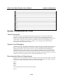
Capturing Up-to-date Still Images.............................................................................5-2
Getting snapshots by URL.................................................................................5-2
Getting snapshots by FTP..................................................................................5-2
Embedding Video in the Homepage ..........................................................................5-2
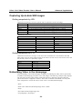
Downloading Event-triggered Snapshots ..................................................................5-3
Getting triggered snapshots by URL .................................................................5-3
Getting triggered snapshots by FTP...................................................................5-4
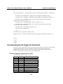
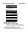
Uploading Snapshots Periodically.............................................................................5-4
Uploading snapshots to an external FTP server.................................................5-4
Sending snapshots to an external SMTP (email) server ....................................5-4
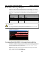
Customizing Homepage Graphics .............................................................................5-5
Command Script for DI/DO & Camera’s Actions Setting.........................................5-5
Command Format ..............................................................................................5-6
Parameter Explanations .....................................................................................5-6
Practical Examples ............................................................................................5-7
URL Commands for DI/DO & Camera’s Actions Setting .........................................5-8
Querying the status of digital inputs ..................................................................5-8
Driving digital outputs.......................................................................................5-8
Moving motorized cameras in PTZ directions...................................................5-8
Recalling camera position..................................................................................5-8
Transparent Remote Serial Driver .....................................................................5-8
URL Commands for System Maintenance ................................................................5-9
Downloading the System Log by FTP...............................................................5-9
Restarting the System by URL ..........................................................................5-9
Restoring Factory Default Settings by URL......................................................5-9
Chapter 6
Upgrading System Firmware.......................................................... 6-1
Using the VPort Installation Wizard to Upgrade Firmware.......................................6-2
Chapter 7
Troubleshooting .............................................................................. 7-1
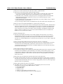
Power On Self Test (POST).......................................................................................7-2
Frequently Asked Questions......................................................................................7-2
Appendix A
URL Commands for VPort 2141 .....................................................A-1
Page URL ................................................................................................................. A-1
System Resource URL .............................................................................................A-2
General CGI URL syntax and parameters ................................................................A-2
Appendix B
Settings of Supported PTZ Cameras.............................................B-1
Appendix C
Camera Control Cable.....................................................................C-1
Appendix D
Time Zone Table ..............................................................................D-1
Appendix E
Technical Specifications ................................................................E-1
Appendix F
Service Information......................................................................... F-1
MOXA Internet Services ...........................................................................................F-2
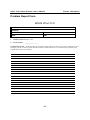
Problem Report Form ................................................................................................F-3
Product Return Procedure..........................................................................................F-4
1
Chapter 1
Introduction
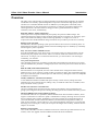
The VPort 2141 is a high-performance networked video encoder. In addition to providing basic
video feeds, many advanced features are also supported to assist the user in setting up surveillance
functions for online applications. The state-of-the-art design provides a good combination of
stability, robustness, ease-of-use, and flexibility.
The following topics are covered in this chapter:
Overview
Package Checklist
Product Features
Typical Applications
Product Description
¾ Front Panel
¾ Rear Panel
VPort 2141 Video Encoder User’s Manual
Introduction
Overview
The VPort 2141 video encoder is a high-performance networked video transmitter. Its powerful
VLIW DSP core and fully optimized algorithm compresses and transmits high quality video in
real-time over a standard TCP/IP network. In addition to providing basic video feeds, many
advanced features are also supported to assist the user in setting up surveillance functions for
online applications. The state-of-the-art design provides a good combination of stability,
robustness, ease-of-use, and flexibility.
Real-time Motion—JPEG compression
Video input can be compressed efficiently and quickly into packets of JPEG images. The
optimized compression engine creates excellent images that do not require a lot of memory space.
This is done without sacrificing remote monitoring capability or storage. Five levels of
compression ratio and three different image resolutions are provided to provide more versatility.
Robust system operation
The industrial, real-time operating system prevents hackers and viruses from wreaking havoc on
both Windows and Linux systems, and the on-board watchdog improves reliability by continually
monitoring the system’s operation.
Easy web access with a standard browser
Since the embedded web server allows users to access the VPort 2141 from anywhere over the
Internet using any popular web browser, there is no need to install new software to access the
VPort 2141. As long as you’re connected to the network, you will be able to view the images
recorded by your cameras.
User password protection
User password protection is provided to prevent malicious intruders from accessing your system.
Once the administrator password is configured, all users will need a password to access the VPort
2141.
Built-in VMD (Video Motion Detection)
External sensors are not required, since the video channel can be configured to detect motion,
making it easy to set up a security system in either your home or office. The customizable settings
allow you to tune the system for both object size and sensitivity, making the VPort 2141 adaptable
to different environments.
Weekly schedule for automated surveillance
A user-defined surveillance schedule will repeat weekly to check security settings and send
notifications or drive external devices, making it easy to install the VPort 2141 in SOHOs, retail
shops, and home security systems.
Flexible I/O control for external devices
One opto-isolated sensor input and one relay output are provided to control external devices,
giving system integrators the option of turning an analog system into an advanced security system.
MOXA SoftDVR™ Lite IP Surveillance Software
To extend the VPort 2141’s capabilities, MOXA SoftDVR Lite IP Surveillance Software, which
supports a maximum of 4 cameras in quad, is included free of charge, allowing users to turn their
PC into a digital video recorder. Scheduling or one-click recording saves important images on
your local hard disk, and the reliable motion detection and instant warning features make you
ready for any situation. A quick and easy to use search and playback function lets you easily find
the image you’re looking for, so that you can inspect the images more carefully, and also save the
output to an AVI file.
Remote system upgrade
Users of the VPort 2141 will have round-the-clock access to the most up-to-date firmware on our
website, with a free upgrade wizard included to facilitate firmware installation.
1-2
VPort 2141 Video Encoder User’s Manual
Introduction
Technical support for developers
The high-performance, cost-effective VPort 2141 can be integrated into many applications, and the
complete programming interface and standard JPEG format makes the developer’s job easy and
straightforward. VPort 2141 applications can be found on MOXA’s website.
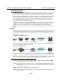
Package Checklist
y
y
y
y
y
y
y
1 VPort 2141 Video Encoder
Camera control cable
2 GPIO terminal connectors
Power adaptor
Quick Installation Guide
Aluminum pieces and 8 screws
Software CD
NOTE: Notify your sales representative if any of the above items is missing or damaged.
Product Features
VPort 2141 video encoders have the following features:
y
y
y
y
y
y
y
y
y
y
y
y
y
y
y
y
Connect analog CCTVs to TCP/IP networks
4-channel video input with 75 ohm impedance DIP switches
MJPEG compression codec
Pre/Post snapshot images—up to 15 images per channel
5 privacy mask functions supported
Set 3 active areas for video motion detection
2 COM ports (1 RS-232 and 1 RS-485) for remote PTZ control
PPPoE to link with xDSL for Internet access supported
Built-in web server for easy configuration
Adjustable network bandwidth
Video stream up to 30/25 frames/sec at 352 x 240 resolution
Quad display at up to 15 frames/sec
4 Digital Inputs and 4 Relay Outputs for sensors and alarms
Automatic remote image retrieval and storage via e-mail, and FTP with event triggering
Supports ActiveX Control SDK to enable easy development of Windows application software
DDNS & UPnP supported
NOTE: ActiveX Control SDK is supported with flexible interface and sample codes for third-party
developers (please contact a MOXA sales representative if you require this SDK).
1-3
VPort 2141 Video Encoder User’s Manual
Introduction
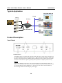
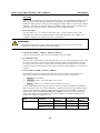
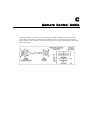
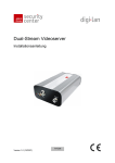
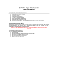
Typical Application
http://192.168.4.100
TCP/IP
Analog
Cameras
DI/ Relay
PC or Server
IP: 192.168.4.100
SoftDVR
Customized AP
Product Description
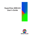
Front Panel
1: RESET button
The RESET button is located on the right side of the VPort 2141’s front panel. The button can
be used to perform two levels of system recovery. “Reset” will force the system to restart, and
“Restore” will restore the factory default settings and then force the system to restart from the
initial state. The “Restore” option is generally used to perform a complete system recovery.
RESET
Click on the “RESET” button once. The system will perform a system diagnosis. If the IP
address is not fixed, you will need to use the VPort installation wizard to locate the VPort, and
get a new IP address from the DHCP server. Note that you can achieve the same effect by
disconnecting and then reconnecting the power supply.
1-4
VPort 2141 Video Encoder User’s Manual
Introduction
RESTORE
If the system is responding or operating abnormally slowly, press and hold the “RESET” button
firmly to load the factory default settings. System diagnosis will begin immediately, and the
“SERIAL” LED will turn on after the system diagnosis finishes. Wait a little bit longer until the
“SERIAL” LED turns off, and then release the “RESET” button. Note that you can achieve the
same effect by clicking the “factory default” link on the configuration page.
2: BNC video inputs
You may attach 1, 2, 3, or 4 cameras to the VPort 2141. To ensure that the correct video
modulation type is detected, cameras should be connected sequentially from “VIDEO 1” to
“VIDEO 4” and powered on before the VPort is powered on.
ATTENTION
Although the analog cameras have 2 different standards, NTSC or PAL, all of the cameras
connected to a VPort 2141 should use the same standard.
3: Camera ID: VIDEO 1, VIDEO 2, VIDEO 3, VIDEO 4
Cameras connected to the VPort 2141 are identified by the port number.
4: 75 Ohm DIP Switch
There are four 75-Ohm DIP switches numbered from “1” to “4” on the front panel. The switches
are used to enable the 75-Ohm resistance video impedance. DIP switches should be turned to
the “ON” position if cameras are connected to the video inputs, and a video loop is not being
used. The switches should be turned to the “OFF” position for high impedance if a video loop is
required.
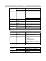
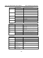
5: System LEDs: POWER, CONNECT, SERIAL
Each time the VPort 2141 video encoder starts up, a Power-On-Self-Test (POST) will be
performed to examine each hardware module. The VPort 2141 has 3 System LEDs:
a.
POWER: power indicator.
b.
CONNECT: checks to see if the VPort 2141 is alive.
c.
SERIAL: checks to see if the RS-232/485 COM ports are in use.
As soon as the administrator plugs in the power connector, both the CONNECT and SERIAL
LED’s will flash, one by one, until the diagnosis is finished. If the result is good, these 2 LEDs
will turn off momentarily, and then follow the pattern shown in the table below. If any of the
modules fails, refer to the Power On Self Test in Chapter 7 for the error pattern, and then
follow the troubleshooting procedures. If the system still does not operate normally, please
contact your reseller for technical service.
Mode
Condition
Ethernet Connection Before installation
After installation
During camera
control
1-5
LED1
(POWER)
ON
ON
ON
LED2
(CONNECT)
OFF
Flash
Flash
LED3
(SERIAL)
OFF
OFF
Flash
VPort 2141 Video Encoder User’s Manual
Introduction
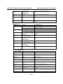
6: Network LEDs: ACTIVE, LINK, FDX
The VPort 2141 has 3 LEDs to show network status when using the 10/100 Mbps Ethernet
connection:
Name
Description
Work Status
ACTIVE
Check if the network is alive
Flashing: Network alive
OFF: Network not alive
LINK
Check the 10/ 100 Mbps Ethernet speed
ON: 100 Mbps
OFF: 10 Mbps
FDX
Check if transmission is full or half duplex
ON: Full Duplex
OFF: Half Duplex
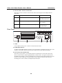
Rear Panel
1
2
3
4
5
6
7
8
9
10
11 12 13
Power OUT: 12 VDC
NO
1
2
Power IN: 12-15V DC/AC
14
15
3
4
5
6
7
8
Relay 3
Relay 4
NO C NC NO C NC
16
DI 1
Relay 2
Relay 1
C NC NO C NC
17
18
19
20
21
9
10
DI 2
11
DI 3
22
23
12
DI 4
24
25
RS-485
13
RS-485
26
POWER IN
12 VDC
14 15 16 17 18 19 20
11
21 22 23 24 25 26
10
COM 1
(RS-232)
10/100 Mbps
Ethernet
7
8
9
7: COM1
Use this RS-232 serial port to connect to an RS-232 PTZ camera.
8: 10/100 Mbps Ethernet
An RJ45 10/100 Mbps Ethernet connector can be connected to an Ethernet network with a UTP
category 5 cable that is shorter than 100 meters (based on the usual Ethernet standard).
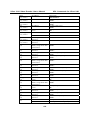
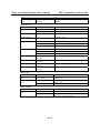
9 & 10: General I/O terminal block
The VPort 2141 provides a very flexible general I/O interface that can be used with security
devices, such as sensors, alarms, lighting fixtures, and door locks. Two green connectors are
included in the package to connect external devices. The general I/O terminal block has 26 pins
for device control. These pins can be divided into three categories based on their function,
including power source, RS-485, and digital input and output.
1-6
VPort 2141 Video Encoder User’s Manual
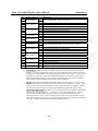
No.
1
2
3
4
5
6
7
8
9
10
11
12
13
14
15
16
17
18
19
20
21
22
23
24
25
26
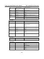
Pin description
Power Output
Relay Output 1
Relay Output 2
Digital Input 1
Digital Input 2
RS-485
Power Input
Relay Output 3
Relay Output 4
Digital Input 3
Digital Input 4
RS-485
Introduction
Regulation
+
NO
C
NC
NO
C
NC
+
+
+
+
NO
C
NC
NO
C
NC
+
+
-
Power Output, Max. 500 mA at 12 VDC
Normal Open, Max. 1A, 24 VDC or 0.5A, 125 VAC
Common, Short with NC at initial state
Normal Close, Max. 1A, 24 VDC or 0.5A, 125 VAC
Normal Open, Max. 1A, 24 VDC or 0.5A, 125 VAC
Common, Short with NC at initial state
Normal Close, Max. 1A, 24 VDC or 0.5A, 125 VAC
Max. 50 mA, 12 VDC
Ground
Max. 50 mA, 12 VDC
Ground
RS-485, Data +
External Power Input, Min. 1.5A, 12-15 VAC or VDC
Normal Open, Max. 1A, 24 VDC or 0.5A, 125 VAC
Common, Short with NC at initial state
Normal Close, Max. 1A, 24 VDC or 0.5A, 125 VAC
Normal Open, Max. 1A, 24 VDC or 0.5A, 125 VAC
Common, Short with NC at initial state
Normal Close, Max. 1A, 24 VDC or 0.5A, 125 VAC
Max. 50 mA, 12 VDC
Ground
Max. 50 mA, 12 VDC
Ground
RS-485, Data -
a.
Power Source: There are 2 ways to connect to the power source. You may use a power
adaptor, or connect through pins 14 and 15 of the terminal block. This power source can
be either AC or DC, and the output range should fall between 12V and 15V. Polarity does
not matter if you use AC. The power output through pins 1 and 2 is fed from the power
adaptor of the video encoder, or pins 14 and 15 if an external power source is attached.
The current from external devices is limited to less than 500 mA.
b.
RS-485: If the device has an RS-485 interface (such as a PTZ camera control), wire the
RS-485 Data+ (PIN 13) and Data- (PIN 26) control lines to the RS-485 “+” and “ –” pins.
If the distance from the controlled device is too long to allow transmit signals accurately,
an external power source may be used to pull the RS-485 signal to the “high” status.
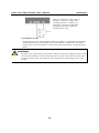
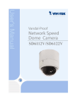
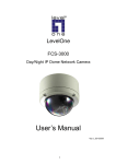
c.
Digital Input/Relay Output: The VPort 2141 video encoder provides 4 digital inputs and 4
relay outputs. The digital input’s “+” pin and “-” pin can be connected to an external
sensor to monitor the voltage. The relay output’s “NO” pin (Normal Open), “NC”
(Normal Close) pin, and “C” pin (Common) can be used to turn an external alarm on or
off. When the system starts up, the “Common” pins of the two relay outputs will short the
“NC” pin. A simple example is illustrated in the diagram below.
1-7
VPort 2141 Video Encoder User’s Manual
Introduction
If DI1 is configured to “rising” status, so
that Relay 1 is driven to “high” status
(resulting in Relay1’s “Common” pin
shorting the “NO” pin), the light bulb
will light up when DI1’s signal will
change from 0V to 12V.
12: POWER IN 12 VDC
Connect the power jack of the included 12 VDC power adaptor. Connecting the power adaptor
should be the last step of installing the video encoder hardware. Administrators can feed an
external power source through pins 11 and 12 of the GPIO terminal block to replace the power
adaptor.
ATTENTION
The VPort 2141 video encoder’s power adaptor, and the external power supply (from pins 14 and
15 of the Terminal Block) cannot be used at the same time. Only one power source can be used
to feed power to the VPort 2141. Improper usage could result in serious damage to your video
encoder.
1-8
2
Chapter 2
Getting Started
This chapter includes information about how to install a VPort 2141 video encoder.
The following topics are covered:
Before Getting Started
Setting up an Ethernet Environment
¾ Cable Connection
¾ Powering on the VPort 2141 Video Encoder
¾ Assigning an IP Address to the VPort 2141 Video Encoder
¾ Accessing the VPort 2141 Video Encoder for the First Time
Mounting the VPort 2141
¾ Panel Mounting
¾ DIN-Rail Mounting
VPort 2141 Video Encoder User’s Manual
Getting Started
Before Getting Started
To adapt easily to different environments, the VPort 2141 automatically detects the attached
interfaces and configures itself appropriately. For this reason, users do not need to worry about
whether the connected cameras are either NTSC or PAL, how to select between Ethernet and
modem, and whether the Ethernet speed is 10 Mbps or 100 Mbps.
In what follows, “user” refers to those who can access the VPort 2141, and “administrator” refers
to the person who knows the root password that allows changes to the VPort 2141’s configuration,
in addition to providing general access. Administrators should read this part of the manual
carefully, especially during installation.
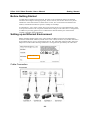
Setting up an Ethernet Environment
Before installing multiple VPort 2141 video encoders at different locations, the administrator
should record the MAC Address (located on the VPort’s label) for future use, and then shut down
all peripheral devices prior to connecting the devices. The video BNC, Ethernet cable, and power
adaptor are needed to take advantage of the basic viewing function provided by the VPort 2141.
00-02-xx-xx-xx-xx
Cable Connection
Front Panel
2-2
VPort 2141 Video Encoder User’s Manual
Getting Started
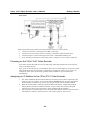
Rear Panel
Perform the following steps before powering on the the VPort 2141 video encoder:
1. Connect your camera’s video output to the BNC video input.
2. Connect I/O devices (such as sensors or alarms) to the VPort’s GPIO terminal block.
3. Connect the hub or switch on the LAN to the VPort’s 10/100 Mbps Ethernet port.
4. If you are using a PTZ camera, connect the VPort’s COM port to your camera’s COM port.
Powering on the VPort 2141 Video Encoder
First, make sure that all cables are correctly and firmly connected, and then turn on the cameras,
sensors, and alarm devices.
Next, power on the VPort 2141 by attaching the VPort 2141’s power adaptor to an electrical outlet.
After the POST (Power-On Self Test) is completed successfully, the VPort 2141 is ready to be
configured. At this point, the network speed and video modulation type will be detected
automatically.
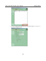
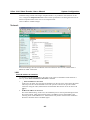
Assigning an IP Address to the VPort 2141 Video Encoder
1.
2.
3.
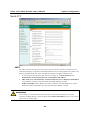
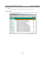
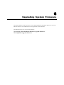
The VPort Installation Wizard will automatically search for VPort products connected to the
same LAN as your computer. You can also click the Search button on the VPort Installation
Wizard window to initiate a new search. Note that the wizard searches by MAC address.
When the wizard finishes searching, the MAC address, IP address, Assigned (IP assigned
status), Model, and Auto IP (indicates whether or not this VPort has an auto IP assigned
function) of the VPort will be listed in the VPort Installation Wizard window.
Select the VPort by checking the box in front of the MAC address, and then click the “Link to
selected device” button to open the VPort’s web console with your web browser.
2-3
VPort 2141 Video Encoder User’s Manual
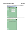
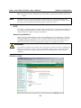
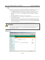
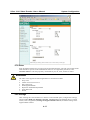
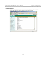
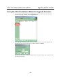
4.
Getting Started
You can modify Host Name, password, and select Date/Time Settings. If you modify any of
the settings, click Next to proceed.
2-4
VPort 2141 Video Encoder User’s Manual
Getting Started
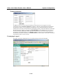
5.
Use the window shown below to modify the IP Address, Subnet mask, IP address of the
Default router, IP address of the Primary DNS, and IP address of the Secondary DNS.
Click Next to proceed.
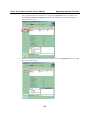
6.
At this point, the setup is complete. Click Previous to make additional changes to the settings,
or click Apply to save the settings to the VPort.
2-5
VPort 2141 Video Encoder User’s Manual
NOTE
Getting Started
The IP assigned status will be listed as Yes if the VPort has been assigned an IP address. If the
status is No, check to see if there is a problem with the DHCP network environment, or if the
model you are using does not support the auto IP assigned function.
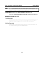
Accessing the VPort 2141 Video Encoder for the First Time
Once the installation is complete, administrators should follow the instructions described in the
next chapter, Accessing the VPort 2141 for the First Time, to make necessary configurations.
Mounting the VPort 2141
Panel Mounting
Users can mount the VPort 2141 directly on the wall by using the 4 fixed aluminum pieces. First,
attach these 4 fixed aluminum pieces to the VPort 2141 with the 8 screws included with the
product. Next, use the 7 mm diameter screws to mount the VPort 2141 to the wall.
DIN-Rail Mounting
MOXA provides a 35 mm DIN-Rail mounting option for use in industrial environments. The
DK-35A DIN-Rail mounting kit can be ordered from MOXA.
2-6
3
Chapter 3
Accessing the VPort 2141
for the First Time
This chapter includes information about how to access the VPort 2141 Video Encoder for the first
time. The following topics are covered:
Accessing the VPort 2141 Video Encoder
¾ Opening Your Browser
¾ Authentication
¾ Installing the Plug-in Application
Functions Featured on the Main Page
¾ Image Mode and Text Mode
¾ Logo and Host Name
¾ Video Quality Selection
¾ Image Size Selection
¾ Camera View Selection
¾ System Configuration
¾ Taking Snapshots
¾ Relay Output Control
¾ Motorized (PTZ) Camera Control
¾ Custom Camera Commands
VPort 2141 Video Encoder User’s Manual
Accessing the VPort 2141
Accessing the VPort 2141 Video Encoder
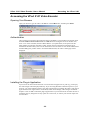
Opening Your Browser
Open your browser, type the VPort’s IP address in the Address box, and then press Enter.
Authentication
After opening your browser and typing the VPort’s IP address, a login window will appear. Enter
the User Name and Password and then click OK. When accessing the VPort for the first time,
enter “root” as the username, and the “MAC address” (in capital letters) as the password. The
MAC address is located on the VPort’s label, and can also be found when running the VPort
Installation Wizard. Primary users will be allowed to access the VPort as soon as the administrator
finishes adding user profiles. After a successful authentication, the VPort’s main page will be
displayed.
Installing the Plug-in Application
If you access the VPort for the first time via a browser that supports server push (e.g., Netscape),
the video images will be displayed directly. If you are using Windows’ Internet Explorer as your
browser, you will be asked to install a new plug-in application provided by the VPort. This plug-in
application has been registered for certification, and is used to display video images via Internet
Explorer. Click on Yes to install the plug-in application. If your browser does not allow the user to
install the plug-in, change the security option to a lower level, or contact your network supervisor
for assistance.
3-2
VPort 2141 Video Encoder User’s Manual
Accessing the VPort 2141
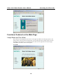
Functions Featured on the Main Page
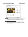
Image Mode and Text Mode
Basic functions are displayed on the VPort’s main page. By default, the main page opens in text
mode, which is shown in the first figure below. The second figure shows image mode. Note that
depending on the PTZ driver or the authorization of the user, the appearance of the main page
could differ from what’s shown in the figures.
Text Mode
3-3
VPort 2141 Video Encoder User’s Manual
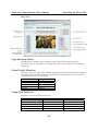
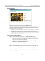
Accessing the VPort 2141
Image Mode
Logo and Host Name
The default logo is MOXA’s logo, and the host name is VPort 2141 Video Encoder. For
customized usage, the administrator can change the layout of the homepage from the Homepage
Layout page.
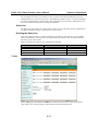
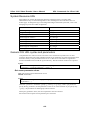
Video Quality Selection
There are 5 options for video quality: Medium, Standard, Good, Detailed, and Excellent. Different
video quality selections result in different sized JPEG files. The table below shows possible file
sizes based on the choice of video quality.
Video Quality
Medium
Standard
Good
Detailed
Excellent
JPEG File Size
6.51 KB
6.69 KB
9.29 KB
14.28 KB
24.24 KB
Image Size Selection
There are 5 options for selecting image sizes:
Video Size (unit: pixels)
Half
Half × 2
Standard
Standard × 2
Double
NTSC
176 ×
352 ×
352 ×
704 ×
704 ×
112
240
240
480
480
3-4
PAL
176 ×
352 ×
352 ×
704 ×
704 ×
144
288
288
576
576
VPort 2141 Video Encoder User’s Manual
Accessing the VPort 2141
ATTENTION
Half × 2 consumes the same file size and bandwidth as Half, but has the same resolution as
Standard. For this reason, the visual effect of Half × 2 is worse than Standard. Likewise,
Standard × 2 consumes the same file size and bandwidth as Standard, but has the same
resolution as Double. For this reason, the visual effect of Standard × 2 is worse than Double.
Camera View selection
A maximum of 4 cameras can be connected to the VPort 2141 at the same time. Users can view
the image of each camera by selecting Video 1, Video 2, Video 3, or Video 4, or selecting Video
All to view all images in Quad screen.
ATTENTION
In Quad viewing mode, in order to fit the monitor screen the maximum image size is only 352 x
240 (NTSC) or 352 x 288 (PAL) for each camera.
System Configuration
When logged in as administrator, a button or text link will show up on the left side of the system
configuration window on main page. For detailed system configuration instructions, refer to
Chapter 4, System Configuration.
Taking Snapshots
Users can take snapshot images for storing, printing, or editing by clicking the Snapshot button,
and then saving the image by clicking the right mouse button.
Relay Output Control
The VPort 2141 has 4 digital inputs and 4 relay outputs for external devices, such as sensors and
alarms. If external devices are attached to the digital output, administrators or permitted users can
click on Open to short the Common and Normal Open pins of the digital output, or click on
Close to short the Common and Normal Close pins of the digital output.
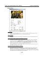
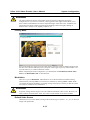
Motorized (PTZ) Camera Control
If a serial device, such as a motorized camera, is attached and correctly configured to the COM
port, the control panel will appear on the permitted users’ main page. The effective buttons will
change color when the cursor is passed over the button. Users can control the pan, tilt, zoom, and
focus functions of motorized cameras. The home button is used to return the camera to the center
position if the camera supports this command. Apart from near and far control for focus, an AUTO
button is provided for setting auto focus mode. To move the motorized camera more precisely, the
speed control for pan and tilt allows users to fine tune the aiming position. Users can also click
directly on any point in the image to force the motorized camera to focus on that point, or select a
preset location from the drop-down list. The list of preset locations is pre-defined by
administrators. The detailed configurations are described in the related section in Chapter 4,
System Configuration.
3-5
VPort 2141 Video Encoder User’s Manual
Accessing the VPort 2141
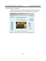
Custom Camera Commands
In addition to the default pan, tilt, zoom, and focus controls, users can define up to five buttons for
controlling attached motorized (PTZ) cameras. Custom commands are set up by administrators,
and are used for functions such as activating or deactivating a camera’s lens wiper. In general,
administrators must refer to the camera’s user’s manual when defining custom commands.
3-6
4
Chapter 4
System Configuration
After installing the hardware, the next task required is to configure the VPort 2141’s settings.
There are 3 configuration methods, based on the type of access: web browser, FTP, and Telnet.
This chapter includes the following sections:
System Configuration by Web Browser
¾ System
¾ Security
¾ Network
¾ DDNS & UPnP
¾ Access List
¾ Video
¾ Camera Control
¾ Homepage Layout
¾ Application
¾ View Log File
¾ View Parameters
¾ Factory Default
System Configuration by FTP
¾ CONFIG.INI
System Configuration by Telnet
¾ Telnet Commands
¾ System Core Debugging
¾ Monitoring the Status of Digital Inputs
¾ Stopping Information Dumping
¾ Querying the Status of Digital Inputs
¾ Setting Digital Outputs
¾ Restoring Factory Default Settings
¾ System Reset
VPort 2141 Video Encoder User’s Manual
System Configuration
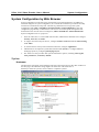
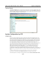
System Configuration by Web Browser
System configuration can be done easily and remotely using Internet Explorer. In addition to
classified categories of system configuration, two wizards are available to provide user-friendly
instructions to facilitate the setup task. Alternatively, administrators can type the system
configuration URL, http://<IP address of Video Encoder>/setup/config.html, to enter the
configuration page directly. Administrators who want to set certain options through the URL
should refer to the relevant section in Chapter 6, URL Commands for Advanced Functions.
System configuration serves 5 purposes:
1.
Since the VPort 2141 is a networked video encoder, administrators should at least configure
Security, Network, and Video.
2.
To support external serial port devices, configure Camera Control and then Camera Setting
under Video.
3.
To use the built-in security and web attraction features, configure Application.
4.
Administrators can adjust the system date and time under System, or configure different
homepage layouts by configuring Homepage layout.
5.
The VPort 2141 also provides other system maintenance options, including View log file,
View parameters, and Factory default.
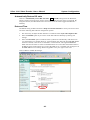
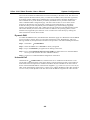
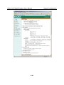
System
Hostname
The host name will appear as the homepage title of the main page and over the video window on
the main page. The maximum string length is 40 characters or 20 characters in
double-byte-character systems, such as Chinese or Japanese systems.
4-2
VPort 2141 Video Encoder User’s Manual
System Configuration
Automatically Restore DO state
There is a Automatically restore DO state after
seconds setting below the Hostname,
which is used to restore the relay output’s status to the default once the relays are triggered. By
using this function, the administrator does not need to close the alarms trigged from the DOs
manually.
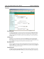
Date and Time
The default setting for Date and Time is Keep current date and time. You may also choose from
one of the following date and time configuration options:
1.
The easiest way to adjust the date and time is to make the VPort Sync with computer time.
2.
Select the Manual option if you wish to set the date and time manually by entering new
settings.
3.
Select the Automatic option to make the VPort synchronize automatically with timeservers
over the Internet every month. However, synchronization may fail if the assigned NTP server
cannot be reached, or the VPort is connected to a local network. Leaving the NTP server
blank will force the VPort to connect to default timeservers. Enter either the Domain name or
IP address format of the timeserver as long as the DNS server is available. Do not forget to set
the Time zone for local settings. Refer to Appendix G for your region’s time zone.
Click on Save to validate the changes.
4-3
VPort 2141 Video Encoder User’s Manual
System Configuration
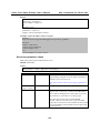
Security
Root password
To change the administrator’s password, type the new password in both the Root password box
and Confirm password box. The passwords you enter will be displayed in asterisks for security
reasons. The maximum string length for a password is 16 characters. After clicking on Save to
validate the new password, a window will open to ask the administrator for the new password to
access the VPort.
Adding users
To add a new user, type the new user’s name in the Username box, the password in the User
password box, and select the authorization level by checking I/O access or Camera control.
Click on Add to insert the entry. The VPort 2141 has a total of 20 user accounts. Each user can be
given independent access rights to the external I/O access and camera control.
Managing users
If the access rights of some users need to be changed, find the user name from the drop down list
and click on Edit. A new window will appear for administrators to change the password and select
a different authorization. Administrators can also delete the selected user by clicking on Delete. A
message window will open next to confirm.
Snapshot mode
A maximum of 20 users can view the VPort’s images at the same time. Administrators can select
the Allow more guests with snapshot mode option to enable the snapshot mode for more users.
In this case, when the number of users exceeds 20, users will see the main page in snapshot mode
4-4
VPort 2141 Video Encoder User’s Manual
System Configuration
instead of seeing normal video images. Snapshot mode is very useful for web attraction. In this
case, configure the Snapshot interval to achieve better performance. Increasing the time interval
between snapshots allows more users to use snapshot mode.
Click on Save to validate changes.
Network
In network settings, there are 2 modes for network connections. One is LAN, and the other is
PPPoE for xDSL connections.
LAN
Reset IP address at next boot
To eliminate errors during installation, the VPort 2141 will be in installation mode whenever it
starts up, unless Reset IP address at next boot is disabled.
1.
□ Reset IP address at next boot
In this case, the VPort 2141 will skip the installation on the next boot, which means the VPort
will always use the current IP address even if the system is rebooted. To provide a stable
connection using the VPort, administrators should enable this function to fix the VPort’s IP
address.
2.
; Reset IP address at next boot
This is the default setting. In this case, the installation process will be performed again when
the system reboots, which means that the VPort’s IP address may be changed due to the
renewing action of the DHCP server. Administrators may need to use the VPort installation
Wizard to check the VPort’s IP address again.
4-5
VPort 2141 Video Encoder User’s Manual
System Configuration
Basic Network Settings
Administrators may need to modify the network settings to connect to an existing network, since
the subnet mask in some broadband services may differ from the default value of 255.255.255.0,
and service providers may assign more specific network settings. Administrators should change
the configuration to the settings given by the service provider. The configuration may include IP
address, Subnet mask, Default router, Primary DNS server, and Secondary DNS server.
After changing network settings, be sure to uncheck the “Reset network at next boot option” to
avoid the installation starting up again the next time the system restarts. Otherwise, existing
network settings will be erased at the next start.
In addition, administrators can limit the bandwidth used by a VPort 2141 according to priority and
importance of location. Limiting bandwidth is useful for balancing network utilization when
multiple VPorts are installed on the same network. This method is more effective than just
changing image quality, and is able to achieve better performance with adequate image size and
quality.
PPPoE
Some environments do not have a LAN and alternative solutions, such as an xDSL connection, are
used to build a remote network. The VPort 2141 supports the PPPoE (PPP over Ethernet) function,
which means that the VPort 2141 can dial up an ISP server by itself to ask the ISP server to assign
an IP address.
Video Server WITHOUT PPPoE
In this case, a router with PPPoE is required to dial up to the ISP and the IP address must be fixed
to retain the video server’s network connection.
Video Server WITH PPPoE
The VPort 2141 with PPPoE function can dial up to an ISP automatically, and the IP address is not
necessary to be fixed, since a startup log will be sent to the administrator by email or FTP (SMTP
and FTP server must be setup) to notify the current IP address once it has been changed by the ISP
server. This method is more cost-effective than applying for a fixed IP address.
How to build the VPort 2141’s PPPoE connection
Step 1: Choose PPPoE connection and configure the User Name, User Password and Confirm
Password provided by the ISP for this service.
Step 2: Configure the SMTP and FTP server for setting up Recipient's Email Address or FTP
remote folder to receive the startup log with assigned IP address if this xDSL connection
is a non-fixed IP address.
Step 3: Change the LAN connection to an xDSL connection.
Step 4: Power on the VPort 2141 and then wait a few seconds for the VPort 2141 to build the
xDSL connection.
4-6
VPort 2141 Video Encoder User’s Manual
System Configuration
Step 5: Check the email or FTP folder to get the IP address assigned to this xDSL connection by
the ISP.
NOTE
The DDNS function provides administrators with the ability to associate a fixed URL to the
VPort 2141. Using a fixed URL eliminates the need of checking the IP address assigned by the
ISP. Please refer to the DDNS function description to learn more about it.
HTTP
For security or network integration, administrators can hide the server from the general HTTP port
by changing the default HTTP port of 80 to a different port number. Administrators should have
enough network knowledge to change the default port.
Save the modification
After all necessary modifications are made, click on Save to store the modifications. A warning
message will appear for confirmation. After clicking on OK, the VPort will automatically restart.
If the Reset network at next boot option is checked, perform the software installation again.
Otherwise, the VPort will boot up automatically using the new configuration settings.
ATTENTION
If you make any changes to the settings on this web page, the system will restart to validate those
changes. Be sure that every field is correctly typed before clicking on Save. If the VPort fails to
respond due to incorrect settings, perform the restore procedure and then rerun the software
installation.
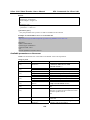
DDNS & UPnP
4-7
VPort 2141 Video Encoder User’s Manual
System Configuration
Two tools are available for administrators to link conveniently to the VPort 2141. The first tool is
DDNS (Dynamic Domain Name System), a combination of DHCP, DNS, and client registration,
all working together. DDNS allows administrators to alias the VPort’s dynamic IP address to a
static hostname in any of the domains provided by the DDNS service providers listed on the
VPort’s DDNS& UPnP configuration page. The VPort will be easier to access from various
locations on the Internet. The second tool is UPnP (Universal Plug & Play), a networking
architecture that provides compatibility between different types of networking equipment,
software, and peripherals of the 400+ vendors that are part of the Universal Plug and Play Forum.
This means that they are listed in the network devices table for the operating system (such as
Windows XP) supported by this function. Users can link to the VPort directly by clicking the
VPort listed in the network devices table.
Dynamic DNS
To enable the DDNS function, the administrator should first apply for a Hostname from the DDNS
service providers’ website. There are 5 providers listed in the VPort: DynDNS.org, TZO.com,
dhs.org, safe100.net, and dyn-interfree.it. Refer to the providers’ rules when enabling the function.
Step 1: Checkmark □ Enable DDNS.
Step 2: Select the DDNS service Provider to which you applied.
Step 3: Key in the Hostname you applied for for linking to the VPort.
Step 4: Key in the Username/E-mail and Password/Key to enable the service from the DDNS
service provider (based on the rules of DDNS websites).
Step 5: Click save to enable the DDNS configuration of the VPort
Universal PnP
Checkmark the □ Enable UPnP box, and then click save to enable the UPnP function. Users
will be able to find and connect to the VPort directly from the operating system’s network device.
If the UPnP network component is installed in Windows XP, the hostname of the VPort will be
shown with bracketed IP address in the Network neighbors, e.g., VPort 2141 (xxx.xxx.xxx.96). In
other words, the hostname of the VPort is “VPort 2141,” and the IP address of the video encoder is
xxx.xxx.xxx.96, which depends on the last value of the IP address assigned to the video encoder.
4-8
VPort 2141 Video Encoder User’s Manual
System Configuration
Mail & FTP
SMTP
The VPort 2141 not only plays the role of server, but also actively connects to outside servers to
send alarm messages or snapshots. If the administrator has set up some applications in either event
mode or sequential mode, the VPort will send out snapshots once these conditions occur.
1.
To activate the e-mail function, enter the correct settings for 1st SMTP (mail) server’s
domain name, account name/password, and Recipient email address.
2.
MTP (mail) server’s domain name, account name/password, and Recipient email address
are provided for a backup connection when the primary SMTP server fails.
3.
Sender email address is the address the email is returned to when the SMTP server rejects
email due to failure. Some ISPs may reject the email if the address is invalid.
ATTENTION
If the settings are correct when the VPort starts up, it will send out a system log via e-mail
instead of uploading the log via FTP. Note that if the Sender email address is not set, the e-mail
system will not work properly.
4-9
VPort 2141 Video Encoder User’s Manual
System Configuration
FTP
FTP can be used by the VPort 2141 to send out alarm messages and snapshots. To send the system
log files described in the above paragraph by FTP, the SMTP server should be erased.
1.
The Local FTP server port can be changed to a setting different from the default setting of
21. Administrators should have enough network knowledge to change the default port.
2.
Administrators must enter the correct 1st FTP Server, 1st FTP user name, and 1st FTP
password.
3.
1st FTP remote folder is the sub-folder in the remote FTP server.
4.
If the remote FTP server’s port is changed to a setting different from 21, be sure to set the real
port to 1st FTP server port.
5.
If the local network is protected by a firewall to prevent it from initiating an FTP connection
from the remote FTP server, you may be able to connect to the FTP server, but not be able to
save a file to the server due to data channel connection failure. Check 1st FTP passive mode
for a passive transfer solution.
6.
Another set of 2nd FTP server settings is also provided for a backup connection.
ATTENTION
With either e-mail or FTP, the primary server information should be entered first. If the primary
server is not set, the related FTP or email will be cancelled. Note that it may take time to connect
to the secondary server if the first server fails, and it may affect some applications when
conditions occur too often.
Access List
4-10
VPort 2141 Video Encoder User’s Manual
System Configuration
The Accessible List allows you to add or remove “Legal” remote host IP addresses to prevent
unauthorized access. Access to the VPort is controlled by IP address. That is, if a host’s IP address
is in the accessible IP table, then the host will be allowed access to the VPort. Administrators can
allow one of the following cases by setting this parameter.
Allow List
The VPort can use the allow list to limit which clients can access the video stream. Administrators
can add ten IP address ranges to forbid access to these clients.
Deleting the Allow List
VPort also supports a deny list, with a maximum of 10 elements. The deny list is given a higher
priority than the allow list. If a client is in both the deny list and allow list, the client will be not
allowed to access video stream.
Refer to the following table for more configuration examples.
Allowable Hosts
Any host
192.168.1.120
192.168.1.1 to 192.168.1.254
192.168.0.1 to 192.168.255.254
Start IP Address
Blank
192.168.1.120
192.168.1.1
192.168.0.1
End IP Address
Blank
192.168.1.120
192.168.1.254
192.168.255.254
Video
On the Video page, checkmark the Enable box to allow the VPort 2141 to show the camera’s
video images. The various settings are described in the following subsections.
4-11
VPort 2141 Video Encoder User’s Manual
System Configuration
Image setting
Time stamp
Checkmark the Time stamp checkbox to show a time stamp on the video images. The time
stamp is captured from the VPort 2141’s on-board real-time clock.
Text on Image
Use this option to label all of the images. A maximum of 14 bytes (14 English characters) are
allowed.
Color, Default quality, Default size, Maximum frame rate
The Color setting depends on the connected camera. Use the “B/W” option to speed up the
operation of the VPort. The Default quality option is the default quality when users first
connect to the VPort. The Default size option is the default resolution of the video window
when the user first connects to the VPort. The Maximum Frame Rate option is the default
frame rate when the camera’s images are displayed by the web server.
After inputting the above settings, click on Save to save the settings to the camera, or click on
Save All to save settings to all 4 cameras.
Brightness, Contrast, Saturation, and Hue
Each field has eleven levels, ranging from -5 to +5. After entering a value, you may click on
preview to see if the settings are appropriate before clicking on Save or Save All. If the
adjustment is not satisfactory, click on Restore to restore the original settings. After finishing
the configuration, click on Close to close this window. If the configurations are changed without
saving, they will only be lost when the system is restarted.
4-12
VPort 2141 Video Encoder User’s Manual
System Configuration
Camera Setting
Camera type
The default camera type for the VPort 2141 is Fixed camera, which means that it is a general
camera without a motorized function. If you wish to select a PTZ camera, you also need to
select the COM port that this PTZ camera is connected to, and the PTZ camera’s ID to
activate it. Click on Save to validate the camera type.
Preset position setting of Motorized PTZ camera
Below the camera type setting is the image of the camera, the PAN/TILT/ZOOM/FOCUS
control buttons, and the preset position settings. For motorized PTZ cameras, use the control
buttons to adjust the positioning and focus of the camera. A maximum of 20 preset positions
can be set up for each channel.
4-13
VPort 2141 Video Encoder User’s Manual
System Configuration
Motion Detection
Three areas of the image can be configured for the VMD (video motion detection) function. The
VMD alarm will only be triggered when the VMD conditions in these 3 specific areas are met.
Each area can be fine tuned to fit the environment for different VMD conditions by setting the
Sensitivity and image change Percentage.
1.
Sensitivity sets the measurable difference between two sequential images to indicate motion.
2.
Percentage sets the minimum size of the image whose motion will be detected (e.g., if
Object size = 30%, then the system will only detect the motion of objects that occupy an area
larger than 30% of the total monitored area; the motion of objects with size less than 30% of
the monitored area will NOT be detected).
How to Set up a VMD condition
Step 1: To enable VMD settings, checkmark the □ Enable Motion Detection box.
Step 2: Click on the New button. A VMD window will pop up. Right click the title bar of this
window to move the location of the VMD window, or drag the boarder to change the
window size so that it fits the desired VMD area.
Step 3: Use Window Name to assign a name to this VMD window (refer to the Trigger
Condition in the Configuration/Application page).
Step 4: Set up the Sensitivity and Percentage parameters by moving the percentage cursor.
Step 5: Click on the Save button to save the settings.
Step 6: To test the VMD condition, check the action of the graphics bar on the left side of the
save button. Wave your hand in front of the camera, in the VMD area, and then note
which color shows up in the graphics bar. Green means VMD is not triggered. Red means
VMD is triggered.
Step 7: Users will see a red frame with the VMD window size in the homepage’s image if the
VMD is triggered.
4-14
VPort 2141 Video Encoder User’s Manual
System Configuration
ATTENTION
The motion detection function is dependent on the environment. When the settings are
configured to be very sensitive to motion, some triggered events might be false alarms, since
there could be small differences between sequential images of the same scene. In addition, the
motion detection alarm could be triggered by the flashing of florescent lights, shifting of
shadows due to changes in the lighting conditions, etc.
Privacy Mask
Five private mask areas can be set up for each camera. The areas appear as filled rectangles (with
fill color set to black) to hide the privacy of objects in that region. A privacy mask window is set
up in the same way as a motion detection window.
Before completing the Video configuration, you should check the Modulation, Default Video
Source, and Bandwidth Limit, as described next.
Modulation
There are 3 types of Modulation. Administrators can set the auto-detected condition during
initialization by selecting Auto, but can still set it manually by selecting NTSC or PAL. When
you change the camera modulation, a warning message will pop up to inform you that the system
will restart to validate the new modulation.
ATTENTION
In general, analog cameras support one of two different standards, NTSC or PAL. However, all
of the cameras connected to the VPort 2141 video encoder should use the same standard.
Default Video Source
Administrators can set the default viewing mode for home page to camera 1, 2, 3, or 4, or show all
images with quad mode.
4-15
VPort 2141 Video Encoder User’s Manual
System Configuration
Bandwidth Limit
The bandwidth limit affects the transmission of video streams. Once a bandwidth limit is set, the
video frame rate will change accordingly. Limiting the bandwidth is useful for balancing network
utilization when multiple VPorts are installed on the same network. This method is more effective
than just changing image quality, and is able to achieve better performance with adequate image
size and quality.
Save
After making all of the necessary modifications, click Save to store the modifications. If you have
changed the modulation type, the VPort will restart automatically.
Camera Control
The Camera Control page includes settings for PTZ driver, and various serial transmission
settings.
The VPort 2141 has 2 COM ports, COM 1 and COM 2, for connecting to external devices, such as
a motorized PTZ (PAN, TILT, ZOOM) controller.
COM 1
COM 2
Interface
RS-232, male DB9
RS-485, Terminal block for Data+, Data-
Speed
Max. 115. 2 Kbps
Max. 115. 2 Kbps
The COM port connection serves 2 purposes:
1.
If the attached device is a PTZ camera, administrators must select the correct PTZ model
under PTZ driver options, since each PTZ camera has its own protocols for the PTZ functions.
Refer to Appendix B, Settings for Supported PTZ Cameras, to see which PTZ cameras are
supported by the VPort 2141. If the attached PTZ camera is not supported by the VPort, select
Custom Camera to enter the proprietary commands for pan, tilt, zoom, and focus control.
2.
If the attached device is not a PTZ camera (e.g., a video multiplexer), select the Generic CGI
command to control the device using CGI commands. For external device control, refer to
Chapter 5, Advanced Applications, under the URL Commands for DI/DO and Camera’s
Actions settings section for more details.
The default setting is None, which means no serial device is connected to the COM port.
4-16
VPort 2141 Video Encoder User’s Manual
System Configuration
PTZ Driver
Since each PTZ camera has its own protocols for the PTZ functions, select the correct PTZ model
under PTZ driver options. If the attached PTZ camera is not supported by the VPort, select
Custom Camera to enter the proprietary commands for pan, tilt, zoom, and focus control.
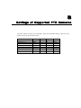
ATTENTION
The VPort 2141 supports the following PTZ drivers and camera models:
1.
2.
3.
4.
5.
6.
7.
Sony Visca
Cannon VCC1\VCC3\VCC4
Pelco D protocol
Samsung/ SmartDome
Dynacolor SmartDome/Dynadome
Liling PIH-7x00
Ernitec
Port Settings
After selecting the correct PTZ driver or Generic CGI command option, configure Port settings,
which includes Baud rate, Data bits, Stop bits, and Parity bit. If the attached device is a PTZ
camera, refer to Appendix B, Settings for Supported PTZ Cameras, for default settings of the
supported PTZ cameras.
4-17
VPort 2141 Video Encoder User’s Manual
System Configuration
Custom command
In addition to pan, tilt, zoom, and preset functions, the VPort 2141 also supports 5 custom
commands. Click on Custom Command to configure, and refer to the manual enclosed with the
attached PTZ camera to set up frequently-used functions. The Command should be entered in
ASCII format. The VPort will translate the commands into binary code and send them out through
the serial port. For instance, a text string of 8101ABCDEF will be translated into five bytes of
hexadecimal 81, 01, AB, CD, and EF. The maximum length of a command string is 60, which is
equivalent to 30 hexadecimal bytes. The Display string is for the text on the command buttons
and should be less than 8 characters. If Custom Camera is selected, there will be more commands
for PTZF that relate to custom camera.
Homepage Layout
The VPort 2141 allows administrators to customize the layout of the its homepage.
4-18
VPort 2141 Video Encoder User’s Manual
System Configuration
Logo graph
1.
Select the blank option to hide the logo figure, which appears in the upper-left corner of the
homepage.
2.
The “default” logo is the MOXA logo.
3.
An external logo or image can be used by selecting the URL option, and typing the url for the
image in the text input box.
Logo link
Use the Logo link option to input the url that visitors are directed to when they click on the logo.
Background graph
As with Logo graph, Background graph gives you the ability to customize the background as
blank, default, or an external image by selecting the URL option, and typing the url for the image
in the text input box.
Font and Background color
The Font color and Background color can be chosen from sixteen custom colors.
ATTENTION
The Background color option is active only when Background graph is set as blank.
Web page display mode
There are two homepage display modes. One is Image mode, which uses icons to link to the
various functions; the other is Text mode, which uses mostly text to link to the various functions.
You may change the string content manually.
ATTENTION
See the Customize graphics in homepage section from Chapter 5 to see how to replace the
default images for the VPort’s log, background, and buttons.
Application
The VPort 2141 provides 4 major applications.
1.
Weekly schedule: Set up the Application schedule by week.
2.
External script files: For advanced applications, you can program command scripts that can
be uploaded to the VPort 2141.
3.
Event operation: Set trigger conditions by selecting Motion Detected, DI Condition, etc.,
and trigger actions by selecting Trigger output alarm while input condition matched, etc.
4.
Sequential mode: Set the sequential snapshot mode to send snapshots by time interval.
You can use combinations of options from the application web page to perform various useful
security applications.
4-19
VPort 2141 Video Encoder User’s Manual
4-20
System Configuration
VPort 2141 Video Encoder User’s Manual
System Configuration
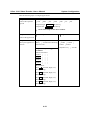
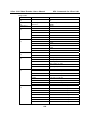
Take the following steps to configure applications.
Step 1:
Weekly schedule
Choose the operation
period
□Sun □Mon
snapshot begin
snapshot end
□Tue □Wed □Thu
00:00:00
00:00:00
□Fri □Sat
[hh:mm:ss]
[hh:mm:ss]
□ All the time except for the above schedule
□ Event operation
□ Sequential mode
Step 3:
Step 3-1: Set up the
Snapshot on :
Set up the application’s
actions
Delay □ seconds before detecting
the next event
□Video1 □Video2 □
Video3 □Video4
Step 2:
Choose the application
Snapshot every □ seconds
Step 3-2: Set up the Trigger
Condition
Motion detected in:
Video 1: □ □ □
Video 2: □ □ □
Video 3: □ □ □
Video 4: □ □ □
DI Condition:
DI 1: ▼ (Disable, High, Low,
Rising, Falling)
DI 2: ▼ (Disable, High, Low,
Rising, Falling)
DI 3: ▼ (Disable, High, Low,
Rising, Falling)
DI 4: ▼ (Disable, High, Low,
Rising, Falling)
4-21
VPort 2141 Video Encoder User’s Manual
System Configuration
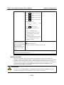
Step 3-3: Set up the Trigger action
DO1:
▼ (Disable, Close, Open)
DO2:
▼ (Disable, Close, Open)
DO3:
▼ (Disable, Close, Open)
DO4:
▼ (Disable, Close, Open)
Send Snapshot on
□ Video 1 □ Video 2 □ Video
3 □ Video 4
Send
▼ (0,1,2,3,4,5,6)
pre-event image(s) when event
occurs
Take □ snapshot(s) with □
seconds interval after the event
□ Send snapshot while trigger
condition(s) match
□ Disable max frame rate setting
for □ second(s) while trigger
condition(s) match
Step 4:
○Send snapshot by email
Choose the snapshot
images sending method
if you choose the
upload snapshot trigger
action or sequential
mode
○Send snapshot by FTP
□FTP put snapshots with date and time suffix
Step 5:
Click Save to enable the applications
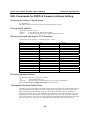
Weekly schedule
The Weekly schedule is provided for daily security applications. Select any weekday from
Monday to Friday with the daily schedule set from 08:00 am to 20:00 pm when no one is available
to perform event checking. If the security system is installed in an office for which no one is
present on nights or weekends, administrators can still set the time period as above, from 08:00 am
to 20:00 pm, but remember to select All the time except for the above schedule to let the
program run during nights and weekends.
ATTENTION
You must select Weekly schedule or All the time except for the above schedule. Otherwise,
the applications described in the following sections will not work properly.
4-22
VPort 2141 Video Encoder User’s Manual
System Configuration
Enable the external script file to exclude the following settings
You can write a script named SCRIPT.TXT to match the additional software according to the
Command Script for DI/DO and Camera’s Actions Setting section from Chapter 5. After
uploading this script to the VPort via FTP, check the option Enable the external script file to
exclude the following settings. Otherwise, the VPort will use the settings under Enable the
external script file to exclude the following settings option.
Event operation
Event operation is for setting security applications.
1.
Delay □ seconds before detecting the next event:
Use this option to set the time interval (in seconds, from 0 to 999) between each event’s
trigger action.
2.
Trigger Condition
3.
a.
Detect motion in. Check the Video 1, Video 2, Video 3, and Video 4 boxes to enable
Video Motion Detection (VMD), which is set on the Video configuration web page (you
may also click on the each hyperlink of video to configure motion detection link
below to configure the appropriate parameters) as the trigger condition. There are 3
check boxes to the right of each video channel, which are for each camera’s VMD area
settings. The VMD Window’s name will appear after the box is set up.
b.
DI Condition. The VPort 2141 supports 4 Digital Inputs. Each DI can be set to High,
Low, Rising, or Falling. An edge trigger (e.g., Rising or Falling) is generally used to
detect the signal from an external sensor.
Trigger Action
You can set 2 trigger actions that determine the reaction after an event occurs. The trigger
actions are relay output alarms and snapshot image.
a.
DO Action. There are 4 DOs (Relay output) for connecting the alarms. You can set the
trigger output alarm when the DI or Video Motion Detection conditions are met. The
Delay □ second(s) after event option will delay the time at which the device attached
to the digital output responds.
b.
Snapshot. You can configure the snapshot action to occur when the DI or Video Motion
Detection conditions are met. By checking the Send snapshot while trigger
condition(s) match, this snapshot trigger action can be enabled. Three snapshots will be
taken when an event occurs.
(1) Pre-event snapshot: The VPort 2141 can provide a maximum of 6 snapshot images
before the event, which can be set up in Send
▼ pre-event image(s) when event
occurs.
(2) Event-triggered snapshot: Once an event occurs, the VPort 2141 will send a
snapshot image at the moment the event is being triggered.
(3) Post-event snapshot: You can determine how many snapshot images will be sent
from the VPort 2141 after the event has been triggered. This is done by configuring
Take □ snapshot(s) with □ seconds interval after the event.
c.
Send snapshot while trigger condition(s) match. To activate the function of snapshot
sent via E-mail or FTP server, this item should be checked.
4-23
VPort 2141 Video Encoder User’s Manual
System Configuration
Sequential Mode
With this feature, the VPort 2141 can upload snapshots periodically to an external e-mail or FTP
server as a live video source. Use the Snapshot every □ seconds setting to set time interval
between uploads. The interval can be set to as little as 1/10 sec to several hours. The external
e-mail or FTP server must be set up in the network configuration page.
Send Snapshot by Email or FTP
Snapshots taken by either event operation or sequential mode can be sent by E-mail or FTP,
which are set on the Mail & FTP configuration page. If email is chosen, the snapshots of the
video channel will be attached to the emails. If FTP is chosen, you can choose to add the date and
time in the file name of the snapshots by checking FTP put snapshots with date and time suffix.
If the snapshots are used as the live video source, the date and time suffix can be eliminated to
update the same source file.
ATTENTION
In Sequential mode, the VPort will send out snapshots according to interval and period settings.
If snapshot files are intended for quick updates, it is better to skip the date and time suffix, in
which case the file name will be video.jpg. If the snapshots are used for occasional monitoring,
suffixing with date and time can help administrators easily classify the snapshots.
ATTENTION
Compared to the FTP method, email will induce more delay, although email can notify users
more promptly.
View Snapshot
You can check the latest pre-event, the moment of the event, and post-event snapshots by clicking
on the View Snapshot button.
4-24
VPort 2141 Video Encoder User’s Manual
System Configuration
Save
Click on Save to activate the applications when you finish updating the settings.
View Log File
The system log contains useful information, including current system configuration and activity
history with timestamp for tracking.
4-25
VPort 2141 Video Encoder User’s Manual
System Configuration
View parameters
Clicking on View parameters allows you to view all system parameters, which are listed by
category. The content is the same as in the VPort 2141’s CONFIG.INI file.
4-26
VPort 2141 Video Encoder User’s Manual
System Configuration
Factory Default
This Factory default function is used to restore the VPort 2141 to its factory default settings. This
means that any changes that were made previously will be lost. After clicking OK, the system will
restart. Note that it will take some time for the restore action to finish, and you will need to run the
software installation program to set up the network.
System Configuration by FTP
CONFIG.INI
FTP can be used to configure the VPort 2141 much more quickly than configuring from a web
browser, particularly when configuring multiple VPort 2141 units. To configure a VPort 2141 by
FTP, first download the parameter file (CONFIG.INI), customize each field, and then upload the
file to the VPort 2141 to install the new settings. To log into the FTP daemon, enter “root” as the
user name, and enter the password that you use when connecting to the Web server. The VPort
2141’s MAC address (no dashes, all letters upper case) is the password for initial access.
The CONFIG.INI file has multiple categories. The category names in square brackets should be in
upper case. The item names in angle braces should be in lower case. Some items related to
disable/enable should use the keywords “YES” or “NO”. The number zero (0) entry in <user
name> and <user password> is for administrators, i.e. “root”. The VPort 2141 will restart
automatically as soon as the file is uploaded and accepted. If you want to cancel the reboot
procedure after transferring the CONFIG.INI file by FTP, then set the first item, <reset system>, to
NO. However, it will only take effect once, and show YES in the download config.ini file the next
time.
A sample CONFIG.INI file is shown in the table below. The text in italics describes the
characteristics of the field, and the bold italic characters are the options for the field.
The following table is an example, with all parameters listed in General command URL format.
4-27
VPort 2141 Video Encoder User’s Manual
;VPort 2141 Video Server Initial Configuration File
[system]
<modelname>
VPort 2141
<hostname>
VPort 2141 Video Server
<ledoff>
0
<timezone>
8
<date>
2005/04/01
<time>
16:28:59
<ntp>
<updateinterval>
0
<serialnumber>
0002D10093E3
<firmwareversion>
VS2403-MOXA-V1.0.1
<supportscriptversion>
0205a
<scriptversion>
0205a
<language>
en
<webpageversion>
VS2403-MOXA-0100b
<di1>
L
<di2>
L
<di3>
L
<di4>
L
<resetdo>
0
<delayresetdo>
1
<ptzenabled>
0
<viewmode>
0
[security]
<usercount>
1
4-28
System Configuration
VPort 2141 Video Encoder User’s Manual
<username>
(0)root
(1)
(2)
(3)
(4)
(5)
(6)
(7)
(8)
(9)
(10)
(11)
(12)
(13)
(14)
(15)
(16)
(17)
(18)
(19)
(20)
<userpass>
(0) 0002D10093E3
(1)
(2)
(3)
(4)
(5)
(6)
(7)
(8)
(9)
(10)
(11)
(12)
(13)
(14)
(15)
(16)
(17)
(18)
(19)
(20)
<userattr>
(0)video1|video2|video3|video4|camctrl|dido|conf
(1)
(2)
(3)
(4)
4-29
System Configuration
VPort 2141 Video Encoder User’s Manual
System Configuration
(5)
(6)
(7)
(8)
(9)
(10)
(11)
(12)
(13)
(14)
(15)
(16)
(17)
(18)
(19)
(20)
System Configuration by Telnet
Telnet Commands
The VPort 2141 has a Telnet daemon that allows administrators to access some seldom used
functions. You will be prompted for a password if you use any general terminal program to
connect to the VPort 2141. The Username is not requested since only administrators can access the
Telnet daemon. The password is the same as that used for web access. After logging in, type
“help” for the command list. If “debug” or “dinote” is not executed, Telnet will disconnect
automatically after being idle for 1 minute.
System Core Debugging
General activities are recorded into SYSTEM.LOG continuously, but information about abnormal
status is not recorded. Administrators can type the “debug” command to examine in-depth core
debugging information. This causes the VPort 2141 to start dumping the detailed debugging
information while the system is running. This is useful for examining if any errors have occurred
when the system operates abnormally. The stored information will be cleared automatically after
the dump. The VPort 2141 will continue to dump new messages unless the connection is broken. If
Telnet is not connected, messages will be stored until administrators re-login.
Monitoring the Status of Digital Inputs
Typing “dinote” will cause the VPort 2141 to send the current status of all digital inputs. After that,
the VPort 2141 will continuously monitor the DI status and send messages only when the state has
changed. For example, after typing “dinote” the terminal will display:
DI1=L
DI2=L
DI3=L
DI4=L
and after DI2 changes to H, the terminal will display
DI2=H
4-30
VPort 2141 Video Encoder User’s Manual
System Configuration
Stopping Information Dumping
Typing “stop” will halt the dumping of debug information and the digital input status.
Querying the Status of Digital Inputs
Typing “diquery” will display the status of all digital inputs once.
Setting Digital Outputs
To set digital output 1 to connect NO with COMMON, type “do1=o”.
To set digital output 1 to connect NC with COMMON, type “do1=c”.
To set digital output 2 to connect NO with COMMON, type “do2=o”.
To set digital output 2 to connect NC with COMMON, type “do2=c”.
Restoring Factory Default Settings
Typing “clear” will cause the VPort 2141 to restore factory settings, but not restart. To validate the
new settings, type “reset” to cause the system to restart.
System Reset
Typing “reset” will cause the VPort 2141 to perform a software reset.
4-31
5
Chapter 5
Advanced Applications
This chapter will introduce more advanced applications.
The following topics are covered in this chapter:
Capturing Up-to-date Still Images
¾ Getting snapshots by URL
¾ Getting snapshots by FTP
Embedding Video in the Homepage
Downloading Event-triggered Snapshots
¾ Getting triggered snapshots by URL
¾ Getting triggered snapshots by FTP
Uploading Snapshots Periodically
¾ Uploading snapshots to an external FTP server
¾ Sending snapshots to an external SMTP (email) server
Customizing Homepage Graphics
Command Script for DI/DO & Camera’s Actions Setting
¾ Command Format
¾ Parameter Explanations
¾ Practical Examples
URL Commands for DI/DO & Camera’s Actions Setting
¾ Querying the status of digital inputs
¾ Driving digital outputs
¾ Moving motorized cameras in PTZ directions
¾ Recalling camera position
¾ Transparent Remote Serial Driver
URL Commands for System Maintenance
¾ Downloading the System Log by FTP
¾ Restart the System by URL
¾ Restoring Factory Default Settings by URL
VPort 2141 Video Encoder User’s Manual
Advanced Applications
Capturing Up-to-date Still Images
Getting snapshots by URL
Administrators and users can use a specific URL to capture the current still image.
Video Channel
Video 1
Video 2
Video 3
Video 4
Quad of all
URL
http://<IP of Video Encoder>/cgi-bin/video1.jpg[?<param>=<value>]
http://<IP of Video Encoder>/cgi-bin/video2.jpg[?<param>=<value>]
http://<IP of Video Encoder>/cgi-bin/video3.jpg[?<param>=<value>]
http://<IP of Video Encoder>/cgi-bin/video4.jpg[?<param>=<value>]
http://<IP of Video Encoder>/cgi-bin/videoall.jpg[?<param>=<value>]
Additional Parameters:
param
Quality
Value
1
2
3
4
5
1
2
3
6
Size
Description
Medium
Standard
Good
Detailed
Excellent
Half
Standard
Double
Half D1
Getting snapshots by FTP
Administrators and users can log in to the VPort 2141 FTP daemon to download the refreshed
JPEG image. The user name and password are the same as for web access. The zero file size in the
file directory means it is captured by request.
Video Channel
Video 1
Video 2
Video 3
Video 4
Quad of all
File Name
Video1.jpg
Video2.jpg
Video3.jpg
Video4.jpg
Videoall.jpg
Embedding Video in the Homepage
When embedding video in the homepage, in addition to indicating the URL, some scripts should
be added to download plug-ins used to view video images. The following example simply displays
title text and a real-time video window in Internet Explorer or Netscape. The user name and
password should be configured in advance. Those who are familiar with HTML can easily add
more components or rewrite the code to create a more vivid and useful homepage.
<html>
<head><title>Video Encoder Sample Page</title></head>
<body>
<h2>Video Encoder Sample Page</h2>
<script language="JavaScript">
5-2
VPort 2141 Video Encoder User’s Manual
Advanced Applications
<!-if ((navigator.appName == "Microsoft Internet Explorer")&&(navigator.platform != "MacPPC"))
{
document.write("<OBJECT ID=\"MjpegControl\" WIDTH=352 HEIGHT=240");
document.write(" CLASSID=\"CLSID:EAA105FE-7BBD-4196-8B96-D46743894195 \" ");
document.write("CODEBASE=\"http://username:[email protected]/plugin
/mjpegcontrol.cab#version=2,0,0,6\">");
document.write("<PARAM NAME=\"VSize\" VALUE=\"2\">");
document.write("<PARAM NAME=\"Url\" VALUE=\"http://username:password@
192.168.0.201/cgi-bin/video.jpg");
document.write("?cam=1&quality=3&size=2\">");
document.write("</OBJECT>");
} else {
document.write("<img width=352 height=240");
document.write("src=\"http://192.168.0.201/cgi-bin/video.jpg?cam=1&quality=3&size=2\">");
}
//-->
</script>
</body>
</html>
Downloading Event-triggered Snapshots
There are 12 video image files for the video channel of three stages: pre-alarm, the moment when
triggered, and post-alarm. Only the snapshots captured by the last event are preserved.
Administrators and users can use FTP or URL to get the saved snapshots. They can also be
browsed from the application page under system configuration.
Getting triggered snapshots by URL
/cgi-bin/ imagebuf.cgi? [?<param>=<value>]
param
cam
bufcnt
value
1
2
3
4
-7
-6
-5
-4
-3
-2
-1
0
Description
Video 1
Video 2
Video 3
Video 4
snapshot before event (oldest)
snapshot before event
snapshot before event
snapshot before event
snapshot before event
snapshot before event
snapshot before event
snapshot upon event
5-3
VPort 2141 Video Encoder User’s Manual
1
2
3
4
5
6
7
Advanced Applications
snapshot after event
snapshot after event
snapshot after event
snapshot after event
snapshot after event
snapshot after event
snapshot after event (latest)
Getting triggered snapshots by FTP
Channel Name
Video 1
Video 2
Video 3
Video 4
Folder Name
snapshot1
snapshot2
snapshot3
snapshot4
File name
pre07.jpg
pre06.jpg
pre05.jpg
pre04.jpg
pre03.jpg
pre02.jpg
pre01.jpg
trg.jpg
pos01.jpg
pos02.jpg
pos03.jpg
pos04.jpg
pos05.jpg
pos06.jpg
pos07.jpg
Description
snapshot before event (oldest)
snapshot before event
snapshot before event
snapshot before event
snapshot before event
snapshot before event
snapshot before event
snapshot upon event
snapshot after event
snapshot after event
snapshot after event
snapshot after event
snapshot after event
snapshot after event
snapshot after event (latest)
Value
-7
-6
-5
-4
-3
-2
-1
0
1
2
3
4
5
6
7
Uploading Snapshots Periodically
Uploading snapshots to an external FTP server
In sequential mode, the VPort 2141 will send out snapshots according to interval and period
settings. If snapshot files are intended for quick updates, it is better to skip the date and time suffix.
The file name will then be video1.jpg, video2.jpg, video3.jpg, and video4.jpg for four channels. If
the snapshots are used for occasional monitoring, using the date and time to suffix the file name
can help administrators classify them easily.
Sending snapshots to an external SMTP (email) server
Compared with the FTP method, email will induce more delay. But the email can notify users for
prompt action.
5-4
VPort 2141 Video Encoder User’s Manual
Advanced Applications
Customizing Homepage Graphics
While in text mode, a small icon named BTN_TEXT.GIF preceding each link can be changed by
administrators. While in image mode, the default method will use the image stored in the Flash
memory. The table below shows the referenced file name and size limitation of each stored image.
Administrators may customize preferred images under the size limit, and then put the image to the
specific name by FTP. Administrators can download the original images before uploading for
backup.
Object
Logo
Background
Link icon
Camera 1 button
Camera 2 button
Camera 3 button
Camera 4 button
Camera All button
Configuration
File name
logo.gif
back.gif
btn_text.gif
btn_cam1.gif
btn_cam2.gif
btn_cam3.gif
btn_cam4.gif
btn_cama.gif
btn_confi.gif
Maximum size
Logo and background share 8K bytes
Logo and background share 8K bytes
2K bytes
5K bytes
5K bytes
5K bytes
5K bytes
5K bytes
5K bytes
ATTENTION
Do not try to upload images for which the file size is larger than that shown in the above table,
since doing so could cause the system to operate in an unstable manner.
FTP usage is illustrated below.
Command Script for DI/DO & Camera’s Actions Setting
In addition to an application wizard, the VPort 2141 provides a more professional command script
for advanced applications. The command script will be executed exclusively using the settings on
the Application page of the system configuration, except for the weekly schedule. To build an
advanced application, follow the steps shown below:
Step 1: Use any text editor to edit the appropriate command script according to the command
format. The script size cannot exceed 500 bytes.
Step 2: Save the script as a file named SCRIPT.TXT.
5-5
VPort 2141 Video Encoder User’s Manual
Advanced Applications
Step 3: Use FTP with administrator’s privilege to upload the script file.
Step 4: Enter the Application page in the system configuration to define the time period in Weekly
Schedule. If it is required to run any time, keep the original settings but check the option All the
time except for the above schedule.
Step 5: Check the option Enable the external script file to exclude the following settings to
activate the command script.
Command Format
[Event][“Operator”Event]……=[Action][+Action]……;
Event
[“Digital Input Number””Digital Input State”]
[“M” “Channel Number…”]
[“Channel Number””Video Input State”]
Operator
“+”:
“*”:
(OR)
(AND)
Action
[(“Delay Time”)“Digital Output Number””Digital Output State”]
[“V”“Channel Number”“P”“Preset Location Number”]
[“W”{“IP”:“Port”}{“Message”}]
[“U”“Method”]
[“S”“Channel Number…”]
[“N”{“filename”}];
Parameter Explanations
Note that in the previous section, items in brackets show the options available for that item. An
explanation of each parameter is given below:
“Digital input number”:
“Digital input state”:
“M”:
“Channel Number”:
“Video input state”:
1 to 4
H (high), L (low), / (low to high), \ (high to low)
motion detection event.
A, B, C, D for channel 1, 2, 3, 4
/ (signal from loss to presence), \ (signal from presence to loss), X (as
long as signal loss)
“Delay time”:
seconds of delay for the following actions after events happen
“Digital output number”: 1 or 2
“Digital output state”:
C (NC), O (NO)
“V”:
set video channel to go to preset location
“P”:
set preset location number to go to preset location
“W”:
send warning to server
“IP”:
server IP
“Port”:
server port
“Message”:
text to be sent to the server
“U”:
upload snapshots
5-6
VPort 2141 Video Encoder User’s Manual
“Method”:
“S”:
“N”:
“;”:
The filename format is,
%a
%c
%y
%M
%d
%h
%m
%s
%t
Advanced Applications
‘F’ is by FTP, ‘M’ is by e-mail
take snapshot on channels
define the format of the filename
end of line
image characterization (pre, trg, pos)
video channel number
year
month
day
hour
minute
second
tenth second
Practical Examples
Command line
MAB=1C;
Description
When any motion is detected on channel 1 or 2, “Normal
Close” of relay output 1 will short with “Common”.
1H*2\=(5)1O;
When DI1 high companied with DI2 transient from high
to low, “Normal Open” of relay output 1 will short with
COMMON in 5 seconds.
B\+C\+D\=W{192.168.0.1:6000}{no If there is no signal on channel 2 or 3 or 4, a message “no
signal!};
signal!” will be sent to port 6000 of 192.168.0.1 once.
2H=VAP15;
When sensor input 2 is high, drive the camera mapped to
video 1 to go to preset location 15.
MCD=UF+SABCD+N{video%c%a@ If any motion is detected on channel 3 or 4, upload
%y%M%d%h%m%s};
snapshots taken on channel 1, 2, 3 and 4. If an event
triggered at 19:05:30 2002/10/15, the snapshot files will
be named as,
[email protected],
[email protected]
[email protected],
[email protected]
[email protected],
[email protected]
[email protected],
[email protected]
[email protected],
[email protected]
[email protected],
[email protected]
ATTENTION
The script file is limited to a maximum of 500 characters. The actual performance will depend on
the complexity of the command script.
5-7
VPort 2141 Video Encoder User’s Manual
Advanced Applications
URL Commands for DI/DO & Camera’s Actions Setting
Querying the status of digital inputs
/cgi-bin/getdi.cgi
The VPort 2141 will return the status of four digital inputs in one line.
Driving digital outputs
/cgi-bin/setdo.cgi?do1=<state>
<number>
1, 2, 3, 4 for DO1, DO2, DO3 and DO4
<state>:
C, O denoting Normal Close or Normal Open respectively.
Moving motorized cameras in PTZ directions
/cgi-bin/control.cgi?<param>=<value>&<param>=<value>……
Param
cam
move
zoom
focus
panspeed
tiltspeed
Value
1
2
3
4
up
down
left
right
home
wide
tele
near
far
auto
-5 to 5
-5 to 5
Description
Video 1
Video 2
Video 3
Video 4
Tilt up
Tilt down
Pan left
Pan right
Return to home position
Zoom in
Zoom out
Focus near
Focus far
Automatic focus
Recalling camera position
/cgi-bin/recall.cgi?cam=<n>&recall=<position>
<n>:
video channel from 1 to 4
<position>:
the text string of a location that is preset in system configuration.
Refer to Camera preset configuration URL for preset function.
Transparent Remote Serial Driver
The VPort 2141 provides highly customized control support for third-party serial interface devices
(other than PTZ cameras). This means that in addition to setting up a custom camera with PAN/
TILT/ ZOOM/ FOCUS commands, users may utilize this mode and introduce a customized
homepage to transmit arbitrary user-defined commands from the user side to the VPort 2141. The
third-party device connected to the serial port of the VPort 2141 will receive the same command
sent by the originator. The user only needs to attach the command in ASCII format after the special
URL. The VPort 2141 will parse the commands and translate into binary code to send out.
5-8
VPort 2141 Video Encoder User’s Manual
Advanced Applications
Send command to device attached to COM1
/cgi-bin/senddata.cgi?com=1&data=123456,ABCDEF&flush=yes&wait=1000&read=6
This hyperlink will inform the VPort 2141 to send out binary format commands to COM1 with
“0x12, 0x34, 0x56” followed by “0xAB, 0xCD, 0xEF”. Each comma separates the commands by
200 milliseconds. “flush=yes” means the receive data buffer of the COM port must be cleared
before it is read. Then read 6 bytes after waiting for 1000 milliseconds. The read data can be up to
128 bytes and will return as ASCII coded hexadecimal value, e.g., 0x41, 0x42, 0x43 read from
COM port will show in the returned homepage as 414243 instead of ABC.
Send command to device attached to COM2
/cgi-bin/senddata.cgi?com=2&data=123456,,,ABCDEF
This hyperlink will inform the VPort 2141 to send a binary format command to COM2 with “0x12,
0x34, 0x56” followed by “0xAB, 0xCD, 0xEF” after 600 milliseconds.
URL Commands for System Maintenance
Downloading the System Log by FTP
In addition to viewing the system log from the web page, administrators can download the system
log file, SYSTEM.LOG, via FTP. To log into the FTP daemon, enter “root” as the user name and
the administrator password used for Web access.
Restarting the System by URL
/cgi-bin/reset.cgi
The above command restarts the VPort 2141 without warning.
Restoring Factory Default Settings by URL
/cgi-bin/restore.cgi
The VPort 2141 will automatically restart after restoring factory default configurations.
5-9
6
Chapter 6
Upgrading System Firmware
The latest firmware for the VPort 2141 can be downloaded from the Support & Service section of
MOXA’s website. Only administrators can upgrade the system firmware.
The following topics are covered in this chapter:
Using the VPort Installation Wizard to Upgrade Firmware
Using FTP to Upgrade Firmware
VPort 2141 Video Encoder User’s Manual
Upgrading System Firmware
Using the VPort Installation Wizard to Upgrade Firmware
1.
Open the VPort Installation Wizard, checkmark the box next to the server whose firmware
you wish to upgrade, and then click the Upgrade button.
2.
Type in the http port number of the video server whose firmware you wish to upgrade, type
the administrator password in the space provided, and then click Retry.
NOTE: If the password is wrong, a message window will appear asking you to check the FTP
port and password again.
6-2
VPort 2141 Video Encoder User’s Manual
Upgrading System Firmware
3.
The program will detect the Video Server. Note that the Upgrade button is grayed out. Use
the Locate the firmware to upgrade navigation tool in the bottom third of the window to
locate the firmware file.
4.
Click on the firmware file name to select it, and then click on the Upgrade button in the upper
left corner of the window.
6-3
VPort 2141 Video Encoder User’s Manual
Upgrading System Firmware
5.
Wait a few seconds for the upgrade process to finish.
6.
When the upgrade process has finished, click Done to close the Update Progress window.
ATTENTION
Do not turn off the power supply of the VPort 2140 video server while the VPort Installation
Wizard is upgrading the firmware. Doing so will cause the firmware upgrade to fail, and you will
need to return the video server to Moxa for repair.
6-4
7
Chapter 7
Troubleshooting
This chapter describes some problems that might occur during installation or operation, and
provides basic solutions to those problems.
The following topics are covered in this chapter:
Power On Self Test (POST)
Frequently Asked Questions
VPort 2141 Video Encoder User’s Manual
Troubleshooting
Power On Self Test (POST)
After the power has been turned on, the VPort 2141 will perform a self-diagnostic to detect any
hardware defects. The CONNECT (LED 2) and SERIAL (LED 3) LEDs will blink during the
POST, and will keep blinking until the POST completes successfully, or a fatal error is detected. If
either status LED indicator is dim to start off with, the LED may be broken.
When certain fatal errors occur, LED2 and LED3 blink in a particular way to indicate the type of
failure, as described in the following table.
LED pattern after POST
LED2 off, LED3 off
Failed function
Ethernet network
LED2 blinks one time and
LED3 blinks 4 times
Ethernet network
LED2 blinks one time and
LED3 blinks 3 times
System
Troubleshooting
1. Check the LINK LED of
the attached port on the
Ethernet switch or hub. If it
is dim, the Ethernet cable
may be loose or shorted.
2. If the cable is OK, the
Ethernet controller is
broken. Ask your reseller
for technical service.
The Ethernet controller is
broken. Ask your reseller for
technical service.
The PCI interface cannot work.
Ask your reseller for technical
service.
ATTENTION
To reduce system failure caused by operation error, always read the related sections in this user’s
manual to prevent unexpected errors caused by “wild-guess configuration.”
Frequently Asked Questions
Q: Why can’t I connect to the VPort after rebooting?
A: The VPort Installation Wizard can find VPorts connected to the same LAN as the computer
running the Wizard. If the VPort’s IP address does not belong to the same LAN as the PC, or is
set to PPPoE, the Installation Wizard will not be able to locate the VPort.
Q: What should I do if I forget my password?
A: You must log in every time you access the VPort 2141. If you are not a permitted user, you may
view the images or control the camera as long as the demo account is opened. The demo
account user may use the username “demo”, which does not require a password, to access
limited features. If you are one of the managed users, you must ask the administrator for the
password the first time. If you are the administrator, there is no way to recover the root
password. The only way to regain access to the VPort 2141 is to restore the factory settings and
reinstall the VPort.
7-2
VPort 2141 Video Encoder User’s Manual
Troubleshooting
Q: Why can’t I watch video from the VPort 2141 after it is authenticated?
A: There are several scenarios that could cause this problem:
1. If you have just installed the VPort 2141, and are unable to watch the video, check if the
video input is enabled, and check the video modulation on the Configuration page.
2. If the VPort 2141 is installed correctly and you are accessing the VPort 2141 for the first
time using Internet Explorer, adjust the security level of Internet Explorer to allow
installation of the plug-in.
3. If the problem still exists after making the adjustment, the current number of users could be
greater than what the system allows.
4. If you are using a demo account, the administrator may have hid the video from public view.
Q: How can I use a url instead of IP address to connect to the VPort 2141?
A: To allow users to connect to the VPort 2141 through an easily memorized name, administrators
must first configure the network’s domain name server. Here is an example: the administrator
installs the VPort 2141 with a reserved IP address and assigns it a name on the domain name
service, then users can connect to the VPort 2141 by typing the web address instead of an IP
address. If there is a DHCP service on the network, the IP address must be excluded in the
DHCP service to prevent an IP conflict.
Q: What is the plug-in for?
A: The plug-in provided by the VPort 2141 is used to display motion pictures on versions of
Internet Explorer that do not support server push technology. If your system does not allow
installation of any plug-in software, the security level of the web browser may need to be
lowered. It is recommended that you consult the network supervisor in your office to adjust the
security level.
Q: Why is the timestamp different from the system time of my PC or notebook?
A: The timestamp is based on the system time of the VPort 2141. It is maintained by an internal
real-time clock, and automatically synchronizes with the time server if the VPort 2141 is
connected to the Internet and the function is enabled. Differences of several hours may result
from the time zone setting.
Q: Why does the image not refresh regularly?
A: In a modem environment, this is because the bandwidth of PPP connections is much lower than
for Ethernet. If the difference of the timestamp is not stable, use the modem property on the
control panel to adjust the UART FIFO to a lower level for both receiving and transmitting. In
an Ethernet environment, it may be due to the time taken for storing snapshots into memory
when events occur.
Q: How many users are allowed to watch the VPort 2141 at the same time?
A: To achieve the best effect, the VPort 2141 will allow a maximum of twenty users to connect at
the same time. Excess users can get an auto-refreshed still image on the homepage instead. It is
recommended to build another web server to host a large quantity of users by retrieving images
from the VPort 2141 periodically.
Q: What video rate does the VPort 2141 support?
A: The JPEG codec can process 30 frames per second internally. However, the overall
performance is subject to many different factors, such as:
1. network throughput
2. bandwidth share
3. number of users
4. number of video inputs accessed at one time
5. viewing complicated objects results in a larger image file
7-3
VPort 2141 Video Encoder User’s Manual
Troubleshooting
6. the level of your PC or notebook that is responsible for displaying images
In general, the transfer rate on a general local network environment can achieve over 200
Kbps, or approximately 10 to 20 pictures per second in a normal environment. The general
frame size is illustrated in the following table for your reference.
Quality setting
Medium
Standard
Good
Detailed
Excellent
Size of each frame
6.51 KB
6.69 KB
9.29 KB
14.28 KB
24.24 KB
Bandwidth demand for 30 fps
1562 Kbps
1606 Kbps
2230 Kbps
3427 Kbps
5818 Kbps
Q: How can I keep the VPort 2141 as private as possible?
A: The VPort 2141 is designed for surveillance purposes and has many flexible interfaces. The
user authentication and special confirmation during installation can keep the VPort 2141 from
unauthorized access. You may also change the HTTP port to a non-public number. You can
check the system log to examine any abnormal activities and trace the origins.
Q: I have a PTZ camera that is not on the support list. How can I control it?
A: The VPort 2141 provides a custom camera command interface to control cameras that are not
supported. The details are described in this manual. Be sure that the COM port settings are
applied to the camera specifications. The camera control cable included is shown in the
package contents. Prepare your own cable if necessary. The general PTZ command is
composed of one start command and one stop command. When editing both commands in the
edit box of the configuration page, use comma(s) to separate commands. Each comma
represents 200 milliseconds. If the user has some serial control device other than the PTZ
camera, the special URL is provided to send the desired commands. For quick access, integrate
the URL to another homepage on your own web server.
Q: Why can I see image files when I use dir in FTP even if the alarm is not triggered?
A: Every time the VPort 2141 starts, it will capture the images as vpre.jpg. If there are previously
saved image files that are not retrieved, the VPort 2141 will keep them until they are accessed.
Q: How will the stored images be processed if the VPort 2141 loses power?
A: If a user has defined the snapshot interval, the VPort 2141 will capture images periodically at
the pre-alarm stage. Once the pre-defined condition is matched, the pre-alarm images will be
kept and the current images will be saved. The subsequent images will be stored at the
post-alarm stage. Users may retrieve these files either by downloading by FTP, or by directing
the VPort 2141 to send the files by e-mail. This means that after monitoring conditions are met,
the VPort 2141 will keep these image files until user retrieval, even if power is lost.
Q: If I set the VPort 2141 to send e-mails of images whenever the conditions are met, will my
e-mail account overflow?
A: It is recommended to use a transient state instead of steady state. For instance, use ‘Input is
Rising’ and ‘Input is Falling’ rather than ‘Input is High’ and ‘Input is Low’ to let the condition
be triggered only when state is changing.
Q: The image is not clear enough. Is anything wrong?
A: The lens can be focused by rotating the outer ring. Rotate it clockwise or counter-clockwise to
focus near or far.
7-4
A
Appendix A
URL Commands for VPort 2141
The VPort 2141 can be easily integrated with existing websites or web control applications using
convenient URLs. This section lists the commands in URL format corresponding to the basic
functions of the VPort 2141. Some RFC standards related to HTML may be a good reference for
implementation of the customized homepage.
Page URL
The configuration page has a frame layout that includes an option list frame and an option page
frame. Except for the configuration page, the Reference URLs shown below link just to the option
page frame. Some pages, such as image quality settings and preset settings, open in a new browser
window. These URLs can be accessed only by administrators.
Homepage name
Reference URL
configuration page
/setup/config.html
system option
/setup/system.vspx
security option
/setup/security.vspx
network option
/setup/network.vspx
DDNS and UPnP option
/setup/ddnsupnp.vspx
mail and FTP option
/setup/mailftp.vspx
access list option
/setup/accesslist.vspx
video option
/setup/video.vspx
image quality option
/setup/imageset.vspx
camera setting option
/setup/camerasetting.vspx
motion detection setting
/setup/motion.vspx
privacy mask setting
/setup/privatemak.vspx
camera control option
/setup/serial.vspx
custom command setting for RS485
/setup/cuscom.vspx
custom command setting for RS232
/setup/cuscom2.vspx
homepage layout option
/setup/layout.vspx
application option
/setup/app.vspx
system log
/setup/logfile.vspx
VPort 2141 Video Encoder User’s Manual
URL Commands for VPort 2141
System Resource URL
Some images are used on the homepage when the homepage layout is in image mode.
Administrators may use the following links to show the images saved on the VPort 2141 on
another page. To change the logo or the background images referenced by the URL, refer to the
homepage layout section under configuration.
Resource name
Reference URL
system logo image
/logo.gif
background image
/back.gif
button image for camera 1
/btn_cam1.gif
button image for camera 2
/btn_cam2.gif
button image for camera 3
/btn_cam3.gif
button image for camera 4
/btn_cam4.gif
button image for quad screen
/btn_cama.gif
button image for configuration
/btn_conf.gif
icon image for link indicator
/btn_text.gif
General CGI URL syntax and parameters
CGI parameters are written in lower-case and as one word without any underscores or other
separators. When the CGI request includes internal server parameters, the internal parameters must
be written exactly as they are named in the server or video server. The CGIs are organized in
function related directories under the cgi-bin directory. The file extension of the CGI is required.
Syntax:
http://<servername>/cgi-bin/<subdir>[/<subdir>...]/<cgi>.<ext>
[?<parameter>=<value>[&<parameter>=<value>...]]
Get server parameter values
Note: This request require administrator access
Method: GET/POST
Syntax:
http://<servername>/cgi-bin/admin/getparam.cgi?[<parameter>]
[&<parameter>…]
where the <parameter> should be <group>[_<name>] or <group>[.<name>] If you do not
specify the any parameters, all the parameters on the server will be returned. If you specify only
<group>, the parameters of related group will be returned.
When query parameter values, the current parameter value are returned.
Successful control requests returns paramter pairs as follows.
A-2
VPort 2141 Video Encoder User’s Manual
URL Commands for VPort 2141
Return:
HTTP/1.0 200 OK\r\n
Content-Type: text/html\r\n
Context-Length: <length>\r\n
\r\n
<parameter pair>
where <parameter pair> is
<parameter>=<value>\r\n
<length> is the actual length of content.
Example: request IP address and it’s response
Request:
http://192.168.0.123/cgi-bin/admin/getparam.cgi?network_ipaddress
Response:
HTTP/1.0 200 OK\r\n
Content-Type: text/html\r\n
Context-Length: 33\r\n
\r\n
network.ipaddress=192.168.0.123\r\n
Set server parameter values
Note: This request requires administrator access
Method: GET/POST
Syntax:
http://<servername>/cgi-bin/admin/setparam.cgi? [nosync=<value>&]<parameter>=<value>
[&<parameter>=<value>…][&return=<return page>]
parameter
nosync
value
0, 1
value to assigned
<group>_<name>.
return
<return page>
description
Specifies that there should be no sync (write) of the
corresponding configuration file on flash. If parameter is
omitted, a sync write will occur.
(note: this parameter must be put at begin of parameter
list)
Assign <value> to the parameter <group>_<name>..
Redirect to the page <return page> after the parameter is
assigned. The <return page> can be a full URL path or
relative path according the the current path. If you omit
this parameter, it will redirect to an empty page.
(note: The return page can be a general HTML
file(.htm, .html) or a Vivotek server script executable
(.vspx) file. It can not be a CGI command. It can not have
any extra parameters. This parameter must be put at end
of parameter list)
A-3
VPort 2141 Video Encoder User’s Manual
URL Commands for VPort 2141
Return:
HTTP/1.0 200 OK\r\n
Content-Type: text/html\r\n
Context-Length: <length>\r\n
\r\n
<parameter pair>
where <parameter pair> is
<parameter>=<value>\r\n
[<parameter pair>]
Only the parameters that you have set and are readable will be returned.
Example: Set the IP address of server to 192.168.0.123
Request:
http://myserver/cgi-bin/admin/setparam.cgi?Network_IPAddress=192.168.0.123
Response:
HTTP/1.0 200 OK\r\n
Content-Type: text/html\r\n
Context-Length: 33\r\n
\r\n
network.ipaddress=192.168.0.123\r\n
Available parameters on the server
NOTE: The bold characters in the table are the default value of each parameter.
Group: System
NAME
hostname
(r/w)
ledoff
(r/w)
date
(r/w)
time
(r/w)
ntp
(r/w)
timezone
(r/w)
updateinterval
(r/w)
serialnumber
(r)
firmwareversion
(r)
VALUE
<text string shorter than 40
characters>
0
1
<yyyy/mm/dd>
<keep>
<auto>
<hh:mm:ss>
<keep>
<auto>
<domain name or IP
address>
-12 ~ 12
0 ~ 2592000
<mac address>
<text string shorter than 39
characters>
A-4
DESCRIPTION
host name of server
<<Wireless>Video Server<with
Pan/Tilt/<Zoom>>>
Do not turn off the led indicator
Turn off the led indicator
year, month and date separated by slash.
keep date unchanged
Using NTP to sync date/time automatically
hour, minute and second separated by colon.
keep date unchanged
Using NTP to sync date/time automatically
NTP server
<skip to invoke default server>
time zone, 8 means GMT +8:00
<8>
0 to Disable automatic time adjustment,
otherwise, it means the seconds between NTP
automatic update interval.
<0>
12 characters mac address without hyphen
connected
The version of firmware, including model,
company, and version number
VPort 2141 Video Encoder User’s Manual
restore
(w)
reset
(w)
0
Restore the system parameters to default value.
Positive integer
Restore the system parameters to default value
and restart the server after <value> seconds.
0 ~ 65535
Restart the server after <value> seconds.
-1
Not restart the server.
do<1~4>
<state>
(w)
di<1~4>
<state>
(r)
supportscriptversion <text string shorter than 10
(r)
characters>
scriptversion
<text string shorter than 10
characters >
language
<text string shorter than 16
characters>
webpageversion
<text string shorter than 39
characters>
enableir(r/w)
0
1
ptzenabled
32-bit integer
(r )
Group: Security
NAME
username_<1~20>
(r/w)
userpass_<0~20>
(r/w)
userattr_<1~20>
(r/w)
usercount
(r)
Group: Network
NAME
resetip
(r/w)(restart)
H – NC connected with COMMON
L – NO connected with COMMON
H – NC connected with COMMON
L – NO connected with COMMON
The version of supported script/webpage
The maximum version of currently installed
script/webpage
The webpage language
The version of webpage
Turn on the IR control
Turn off the IR control
Indicate the operations of server supported
VALUE
<text string shorter than 16
characters>
<text string shorter than 14
characters>
DESCRIPTION
change user name.
<blank>
change user’s password.
The UserPass_0 is root’s password.
<blank>
[dido][|talk][|listen][|camctrl change user’s privilege. The privilege can be the
][|conf]
combination of
dido – Permit I/O access
talk – Permit to talk to server
listen – Permit to listen from server
camctrl – Permit to do server control
conf – Permit to change server’s configuration
<blank>
1 ~ 21
The current account number on the server
including root.<1>
VALUE
1
DESCRIPTION
enable to get ipaddress, subnet, router, dns1,
dns2 from DHCP server at next reboot
Using preset ipaddress, subnet, router, dns1, dns2
0
ipaddress
(r/w) (restart)
URL Commands for VPort 2141
<IP address>
IP address of server
<192.168.0.99>
A-5
VPort 2141 Video Encoder User’s Manual
URL Commands for VPort 2141
subnet
(r/w) (restart)
router
(r/w) (restart)
dns1
(r/w) (restart)
dns2
(r/w) (restart)
httpport
(r/w) (restart)
networktype
(r/w) (restart)
subnet mask
<255.255.255.0>
<IP address>
default gateway
<blank>
<IP address>
primary DNS server
<blank>
<IP address>
secondary DNS server
<blank>
<positive number less than HTTP port
65535>
<80>
LAN
0
1
PPPoE
pppoeuser
(r/w) (restart)
pppoepass
(r/w) (restart)
smtp1
(r/w)
<text string shorter than 63
characters>
<text string shorter than 63
characters>
<domain name or IP
address, string shorter than
40 characters>
<string shorter than 80
characters>
<text string shorter than 63
characters>
<text string shorter than 15
characters>
<domain name or IP
address, string shorter than
40 characters>
<text string shorter than 80
characters>
<text string shorter than 63
characters>
<text string shorter than 15
characters>
<text string shorter than 80
characters>
<positive number less than
65535>
<domain name or IP
address, string shorter than
40 characters >
<positive number less than
65535>
<text string shorter than 63
characters>
<text string shorter than 15
characters>
<text string shorter than 40
characters>
1
User name of PPPoE
primary FTP port
<21>
user name for primary FTP server
<blank>
password for primary FTP server
<blank>
upload folder in primary FTP server
<blank>
Enable passive mode of primary FTP server
0
Disable passive mode of primary FTP server
mailto1
(r/w)
mailuser1
(r/w)
mailpass1
(r/w)
smtp2
(r/w)
mailto2
(r/w)
mailuser2
(r/w)
mailpass2
(r/w)
returnemail
(r/w)
localftpport
(r/w)
ftp1
(r/w)
ftpport1
(r/w)
ftpuser1
(r/w)
ftppass1
(r/w)
ftpfolder1
(r/w)
ftppasvmode1
(r/w)
<IP address>
A-6
Password of PPPoE
primary SMTP server
<blank>
mail recipient address
<blank>
User name of primary smtp server
<blank>
Password of primary smtp server
<blank>
secondary SMTP server
<blank>
mail recipient address
<blank>
User name of secondary smtp server
<blank>
Password of secondary smtp server
<blank>
return email address
<blank>
FTP port
<21>
primary FTP server
<blank>
VPort 2141 Video Encoder User’s Manual
ftp2
(r/w)
ftpport2
(r/w)
ftpuser2
(r/w)
ftppass2
(r/w)
ftpfolder2
(r/w)
ftppasvmode2
(r/w)
Group: DDNS
NAME
enable
(r/w)
provider
(r/w)
hostname
(r/w)
usernameemail
(r/w)
passwordkey
(r/w)
update
(w)
Group: UPNP
NAME
enable
(r/w)
Group: IPFilter
NAME
allowstart_<0-9>
(r/w)
allowend_<0-9>
(r/w)
denystart_<0-9>
(r/w)
denyend_<0-9>
(r/w)
URL Commands for VPort 2141
<domain name or IP
address, string shorter than
40 characters >
<positive number less than
65535>
<text string shorter than 63
characters>
<text string shorter than 15
characters>
<text string shorter than 40
characters>
1
secondary FTP port
<21>
user name for secondary FTP server
<blank>
password for secondary FTP server
<blank>
upload folder in secondary FTP server
<blank>
Enable passive mode of primary FTP server
0
Disable passive mode of primary FTP server
secondary FTP server
VALUE
0, 1
DESCRIPTION
Enable or disable the dynamic dns.
<0>
1~4
dyndns.org (dynamic)
dyndns.org (custom)
tzo.com
dhs.org
<1>
Text string shorter than 127 Your dynamic hostname.
characters.
<blank>
Text string shorter than 63 Your user or email to login ddns service provider
characters.
<blank>
Text string shorter than 20 Your password or key to login ddns service
characters.
provider
<blank>
0, 1
Update the above ddns settings to take effect
VALUE
0, 1
DESCRIPTION
Enable or disable the UPNP service.
<1>
VALUE
DESCRIPTION
1.0.0.0 to 255.255.255.255 Allowed starting RTSP connection IP address
<1.0.0.0>
1.0.0.0 to 255.255.255.255 Allowed ending RTSP connection IP address
<255.255.255.255>
1.0.0.0 to 255.255.255.255 Denied starting RTSP connection IP address
<blank>
1.0.0.0 to 255.255.255.255 Denied ending RTSP connection IP address
<blank>
A-7
VPort 2141 Video Encoder User’s Manual
Group: Video
NAME
enable
(r/w)
text
(r/w)
Codectype (r)
defaultsource
(r/w)
Size
(r/w)
URL Commands for VPort 2141
VALUE
0, 1
DESCRIPTION
Enable or disable the channel.
<1>
<text string shorter than 14 enclosed caption
characters>
<blank>
1
MJPEG
0
Video 1
1
Video 2
2
Video 3
3
Video 4
4
Video all
1
2
3
half
half x 2
normal
4
normal x 2
5
double
6
half D1
color
(r/w)
0
monochrome
1
color
quant
(r/w)
1
2
lowest quality of video
lower quality of video
3
normal quality of video
4
higher quality of video
5
highest quality of video
64000
128000
set bit rate to 64K bps
set bit rate to 128K bps
256000
set bit rate to 256K bps
384000
set bit rate to 384K bps
512000
set bit rate to 512K bps
768000
1000000
1200000
1
set bit rate to 768K bps
set bit rate to 1000K bps
set bit rate to 1200K bps
set maximum frame rate to 1 fps
2
set maximum frame rate to 2 fps
3
set maximum frame rate to 3 fps
5
set maximum frame rate to 5 fps
10
set maximum frame rate to 10 fps
15
set maximum frame rate to 15 fps
20
set maximum frame rate to 20 fps
25
set maximum frame rate to 25 fps
bitrate
(r/w)
maxframe
(r/w)
A-8
VPort 2141 Video Encoder User’s Manual
URL Commands for VPort 2141
30 (for NTSC only)
set maximum frame rate to 30 fps
0
NTSC
1
PAL
2
AUTO
0
NTSC
1
PAL
flip
(r/w)
1
flip image
0
normal image
mirror
(r/w)
1
mirror image
0
normal image
modulation
(r/w)
actualmodulation
(r)
imprinttimestamp 1
(r/w)
0
Group: Image
NAME
brightness
(r/w)
saturation
(r/w)
contrast
(r/w)
hue
(r/w)
mode
(w)
Overlay time stamp on video
Do not overlay time stamp on video
VALUE
<-5 to 5>
Preview
DESCRIPTION
Adjust brightness of image according to mode
settings. <0>
Adjust saturation of image according to mode
settings. <0>
Adjust contrast of image according to mode
settings. <0>
Adjust hue of image according to mode settings.
<0>
Apply the parameter of image but not save
Restore
Restore the last saved image parameters
Save
Directly save the adjust image parameters
<-5 to 5>
<-5 to 5>
<-5 to 5>
Group: Motion1~4
NAME
VALUE
enabled
0
(r/w)
1
DESCRIPTION
disable motion detection
enable motion detection
disable motion window
winenabled_<1-3> 0
(r/w)
1
enable motion window
winname_<1-3>
(r/w)
winleft_<1-3>
(r/w)
wintop_<1-3>
(r/w)
name of motion window
<blank>
Left coordinate of window position.
<0>
Top coordinate of window position.
<0>
winwidth_<1-3>
(r/w)
<text string shorter than 14
characters >
0 to 352 for CCD
0 to 320 for CMOS
0 to 288 for PAL
0 to 240 for
NTSC & CMOS
0 to 352 for CCD
0 to 320 for CMOS
A-9
Width of motion detection window.
<0>
VPort 2141 Video Encoder User’s Manual
winheight_<1-3>
(r/w)
0 to 288 for PAL
0 to 240 for
NTSC & CMOS
winobjsize_<1-3> 0 to 100
(r/w)
winsensitivity_<1- 0 to 100
3>
(r/w)
update
1
(w)
Group: Mask1~4
NAME
enabled
(r/w)
URL Commands for VPort 2141
Height of motion detection window.
<0>
Percent of motion detection window
<0>
Sensitivity of motion detection window
<0>
Update the above motion detection settings to take
effect
VALUE
0
DESCRIPTION
disable privacy mask
1
enable privacy mask
disable privacy mask window
winenabled_<1~3> 0
(r/w)
1
enable privacy mask window
winname_<1~3>
(r/w)
winleft_<1~3>
(r/w)
wintop_<1~3>
(r/w)
name of privacy mask window
<blank>
Left coordinate of window position.
<0>
Top coordinate of window position.
<0>
<text string shorter than 14
characters >
0 to 352 for CCD
0 to 320 for CMOS
0 to 288 for PAL
0 to 240 for
NTSC & CMOS
winwidth_<1~3> 0 to 352 for CCD
(r/w)
0 to 320 for CMOS
winheight_<1~3> 0 to 288 for PAL
(r/w)
0 to 240 for
NTSC & CMOS
update
1
(w)
Group: CAMCTRL1~4
NAME
VALUE
-5 to 5
panspeed
(r/w)
-5 to 5
tiltspeed
(r/w)
autospeed
-5 to 5
(r/w)
axisx
-104 to 104
(r )
axisy
-15 to 28
(r )
dwelling
0 to 9999
(r/w)
presetname_<0~9> Text string shorter than 40
(r/w)
characters.
presetpan_<0~9> -104 to 104
(r/w)
presettilt_<0~9>
-15 to 28
A-10
Width of privacy mask window.
<0>
Height of privacy mask window.
<0>
Update the above privacy mask settings to take
effect
DESCRIPTION
Pan speed
<0>
Tilt speed
<0>
Auto pan speed
<0>
X coordinate of server position
<0>
Y coordinate of server position
<0>
Time to dwelling when patrol
<1>
The name of preset location
<blank>
The pan coordinate of preset location.
<0>
The tilt coordinate of preset location.
VPort 2141 Video Encoder User’s Manual
URL Commands for VPort 2141
(r/w)
<0>
patrolname_<0~19> Text string shorter than 40 The name of patrol location
(r/w)
characters.
<blank>
Group: Layout
NAME
layouttype
VALUE
1
DESCRIPTION
Image mode
2
Text mode
fontcolor
0-15
Font color <1>
backgroundcolor
0-15
Link color <0>
logotype
1
Blank
2
Default
3
URL
1
Blank
2
Default
3
URL
Text string shorter than 80
characters.
Text string shorter than 80
characters.
Text string shorter than 80
characters.
Text string shorter than 16
characters.
The location of logo graph
backgroundtype
logosource
backgroundsource
logolink
videolinkname
The location of background graph
The web site link for logo
The name of video link
Group: App
NAME
scriptname
(r/w)
enablescript
(r/w)
VALUE
<text string shorter than
255 characters>
0
DESCRIPTION
File name of script
<script.vssx>
Disable script
1
Enable script
Group: Feature
NAME
event
(r/w)
VALUE
0
DESCRIPTION
1
support motion detection/dido/video loss
information in video bitstream
A-11
B
Appendix B
Settings of Supported PTZ Cameras
Since the COM port settings can be adjusted to other than the default settings, check the correct
default settings for the attached camera.
Camera model
Baud rate Data bits
Sony VISCA
9600
8
Canon VC-C1
9600
8
Canon VC-C3
9600
8
Canon VC-C4
9600
8
Pelco D protocol
2400
8
DynaDome/SmartDOME 9600
8
Ernitec
9600
8
Lilin
9600
8
Stop bit
1
2
2
1
1
1
1
1
Parity bit
None
None
None
None
None
None
None
None
C
Appendix C
Camera Control Cable
The included cable can be used to control motorized cameras of desktop types from Sony and
Canon. The pin assignment is illustrated in the following chart. To control cameras of another
brand, check the user’s manual of the motorized camera to see if the pin assignment of the control
cable is appropriate.
D
Appendix D
Time Zone Table
The hour offsets for different time zones are shown below. You will need this information when
setting the time zone in automatic date/time synchronization. GMT stands for Greenwich Mean
Time, which is the global time that all time zones are measured from.
(GMT-12:00)
(GMT-11:00)
(GMT-10:00)
(GMT-09:00)
(GMT-08:00)
(GMT-07:00)
(GMT-07:00)
(GMT-07:00)
(GMT-06:00)
(GMT-06:00)
(GMT-06:00)
(GMT-06:00)
(GMT-05:00)
(GMT-05:00)
(GMT-05:00)
(GMT-04:00)
(GMT-04:00)
(GMT-04:00)
(GMT-03:30)
(GMT-03:00)
(GMT-03:00)
(GMT-03:00)
(GMT-02:00)
(GMT-01:00)
(GMT-01:00)
(GMT)
(GMT)
(GMT+01:00)
(GMT+01:00)
(GMT+01:00)
(GMT+01:00)
(GMT+01:00)
(GMT+02:00)
(GMT+02:00)
(GMT+02:00)
International Date Line West
Midway Island, Samoa
Hawaii
Alaska
Pacific Time (US & Canada), Tijuana
Arizona
Chihuahua, La Paz, Mazatlan
Mountain Time (US & Canada)
Central America
Central Time (US & Canada)
Guadalajara, Mexico City, Monterrey
Saskatchewan
Bogota, Lima, Quito
Eastern Time (US & Canada)
Indiana (East)
Atlantic Time (Canada)
Caracas, La Paz
Santiago
Newfoundland
Brasilia
Buenos Aires, Georgetown
Greenland
Mid-Atlantic
Azores
Cape Verde Is.
Casablanca, Monrovia
Greenwich Mean Time: Dublin, Edinburgh, Lisbon, London
Amsterdam, Berlin, Bern, Stockholm, Vienna
Belgrade, Bratislava, Budapest, Ljubljana, Prague
Brussels, Copenhagen, Madrid, Paris
Sarajevo, Skopje, Warsaw, Zagreb
West Central Africa
Athens, Istanbul, Minsk
Bucharest
Cairo
VPort 2141 Video Encoder User’s Manual
(GMT+02:00)
(GMT+02:00)
(GMT+02:00)
(GMT+03:00)
(GMT+03:00)
(GMT+03:00)
(GMT+03:00)
(GMT+03:30)
(GMT+04:00)
(GMT+04:00)
(GMT+04:30)
(GMT+05:00)
(GMT+05:00)
(GMT+05:30)
(GMT+05:45)
(GMT+06:00)
(GMT+06:00)
(GMT+06:00)
(GMT+06:30)
(GMT+07:00)
(GMT+07:00)
(GMT+08:00)
(GMT+08:00)
(GMT+08:00)
(GMT+08:00)
(GMT+08:00)
(GMT+09:00)
(GMT+09:00)
(GMT+09:00)
(GMT+09:30)
(GMT+09:30)
(GMT+10:00)
(GMT+10:00)
(GMT+10:00)
(GMT+10:00)
(GMT+10:00)
(GMT+11:00)
(GMT+12:00)
(GMT+12:00)
(GMT+13:00)
Harare, Pretoria
Helsinki, Kyiv, Riga, Sofia, Tallinn, Vilnius
Jerusalem
Baghdad
Kuwait, Riyadh
Moscow, St. Petersburg, Volgograd
Nairobi
Tehran
Abu Dhabi, Muscat
Baku, Tbilisi, Yerevan
Kabul
Ekaterinburg
Islamabad, Karachi, Tashkent
Chennai, Kolkata, Mumbai, New Delhi
Kathmandu
Almaty, Novosibirsk
Astana, Dhaka
Sri Jayawardenepura
Rangoon
Bangkok, Hanoi, Jakarta
Krasnoyarsk
Beijing, Chongqing, Hongkong, Urumqi
Taipei
Irkutsk, Ulaan Bataar
Kuala Lumpur, Singapore
Perth
Osaka, Sapporo, Tokyo
Seoul
Yakutsk
Adelaide
Darwin
Brisbane
Canberra, Melbourne, Sydney
Guam, Port Moresby
Hobart
Vladivostok
Magadan, Solomon Is., New Caledonia
Auckland, Wellington
Fiji, Kamchatka, Marshall Is..
Nuku’alofa
D-2
Introduction
E
Appendix E
Technical Specifications
System
CPU: Trimedia PNX1302
RAM: 32MB SDRAM
ROM: 4MB FLASH ROM
Networking
Adjustable bandwidth limit
LED Indicators
NETWORK:
ACTIVE, LINK, FDX (full duplex)
SYSTEM:
POWER, CONNECT, SERIAL
Protocols
Dimensions
TCP/IP, HTTP, SMTP, FTP, Telnet, NTP, DNS,
146.2 x 163.2 x 40 mm (W x D x H)
DDNS, DHCP, UPnP and PPPoE
Weight
Net. 820g
Ethernet
10BaseT Ethernet or 100BaseT Fast Ethernet
Power
auto negotiation
Consumption: near 8W
Input: 100-240VAC, 50/60Hz, 0.4A
Video
Output: 12VDC, 1.5A
Algorithms Supported
MJPEG
External Power Supply: 12VDC, min. 15W
Video Inputs and Outputs
Operating Environment
4 BNC video inputs with 75Ω terminal switch
Operating Temperature: 0 to 65°C/ 32 to 149°F
NTSC/PAL auto-sensing
Storage Temperature: -40 to 70°C/ -14 to 158°F
Humidity: 95%RH
Features
Alarm Features
Adjustable image size and quality
4-channel motion detection with object size and
B/W or color control
sensitivity
Quad screen display
Daily repeat timing schedule
Timestamp and text overlay
Pre/trrgger/post alarm
5 privacy masks for each camera
Automatic transfer of stored images via email or
Three configurable motion detection windows FTP with event-triggered actions
Resolution
NTSC
Up to 30 frames at 176x112
Up to 30 frames at 352x240
Up to 10 frames at 704x480 or quad
PAL
Up to 25 frames at 176x144
Up to 25 frames at 352x288
Up to 10 frames at 704x576
PAN/TILT/ZOOM
Multiple PTZ camera control through RS-232 or
RS-485
Supported devices and protocols:
Sony VISCA protocol, Canon VC-C1, VC-C3,
VC-C4, Dynacolor SmartDOME, Samsung
SmartDome, Pelco D-protocol, Lilin
Speeddome, Ernitec Speeddome
CGI command serial driver is supported
Viewing System Requirement
VPort 2141 Video Encoder User’s Manual
Up to 15 frames for Quad
Technical Specifications
Internet Explorer 5.x or above,
Netscape Navigator 4.x or above
Serial Port
COM1
DB9 RS-232 or RS-485 Terminal block (PTZ
camera control) max.115.2Kbps
COM2
RS-485 (PTZ camera control)
General I/O
4 Digital inputs (max. 12VDC 50 mA)
4 Relay outputs (max. 24 VDC 1A, 125 VAC
0.5A)
E-2
Bundled Free Software
SoftDVR Lite IP Surveillance software for
viewing and recording
F
Appendix F
Service Information
This appendix shows you how to contact MOXA for information about this and other products,
and how to report problems.
In this appendix, we cover the following topics.
MOXA Internet Services
Problem Report Form
Product Return Procedure
VPort 2141 Video Encoder User’s Manual
Service Information
MOXA Internet Services
Customer satisfaction is our number one concern, and to ensure that customers receive the full
benefit of our products, MOXA Internet Services has been set up to provide technical support,
driver updates, product information, and user’s manual updates.
The following services are provided
E-mail for technical [email protected]
World Wide Web (WWW) Site for product information:
.............................http://www.moxa.com
F-2
VPort 2141 Video Encoder User’s Manual
Service Information
Problem Report Form
MOXA VPort 2141
Customer name:
Company:
Tel:
Fax:
Email:
Date:
1.
MOXA Product: VPort 2141
2.
Serial Number:
_________________
Problem Description: Please describe the symptoms of the problem as clearly as possible, including any error
messages you see. A clearly written description of the problem will allow us to reproduce the symptoms, and
expedite the repair of your product.
F-3
VPort 2141 Video Encoder User’s Manual
Service Information
Product Return Procedure
For product repair, exchange, or refund, the customer must:
Provide evidence of original purchase.
Obtain a Product Return Agreement (PRA) from the sales representative or dealer.
Fill out the Problem Report Form (PRF). Include as much detail as possible for a shorter
product repair time.
Carefully pack the product in an anti-static package, and send it, pre-paid, to the dealer. The
PRA should be visible on the outside of the package, and include a description of the problem,
along with the return address and telephone number of a technical contact.
F-4