1
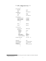
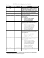
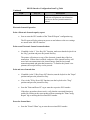
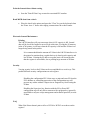
Wrenchman, Inc.
10K120 Interface
for
2127 POS Printer Replacement
Installation and Setup Guide
November 13, 2003
1
Introduction
The Wrenchman 10K120 interface enables the use of an Axiohm A758 or A760
thermal printer with the NCR 2127 POS system.
Advantages
• Electronic Journal 1
• MICR capability 2
• Print up to 4 Graphic Logos per receipt
• 2-Color Logos 3
• USB port for future use
• Easier receipt paper loading
• Faster and quieter printing
• Lower maintenance costs
Installation and Setup
Setup of the Axiohm printer
• Unpack the printer and accessories.
• Locate the Setup Guide Chapter in the“Owner’s Guide” 4 and follow the steps
to setup and install the printer.5
• Verify that the settings on the “Diagnostic Form” are the same as below.6
1
The 10K120 interface has Flash memory to support Electronic Journal, when using the A758 printer.
Enabled by the Dumac 2127 register user exit.
3
Available only on the A760 printer.
4
Axiohm’s “Owner's Guides” are available online at www.axiohm.com.
5
Power the printer and check that the printer’s green light is ON.
6
See the Printer Configuration section in Using the Printer chapter, pages 34-41 in the "Owner’s Guide",
January 2001, to change settings. Incorrect settings will result in unpredictable printing and operation.
2
2
*** A758 – Diagnostics Form 7 ***
•
•
•
Boot Firmware
Revision
CRC
P/N
Flash Firmware
Revision
CRC
P/N
: V3.10
: 184C
: 189-1076109C
: V4.20
: 19AB
: 189-1076110E
H/W parameters
Flash Memory Size
Flash Logos/Fonts
Flash User Storage
SRAM Size
: 512 kbytes
: 64 kbytes
: 64 kbytes
: 256 kbytes
•
•
•
Knife
: Enabled
•
MICR
: Enabled
Comm. Interface
•
Interface Type
Parameters
Baud Rate
Data Bits
Stop Bit
Parity
Flow Control
Reception Errors
Alternate DTR/DSR
Resident Code Pages
: RS232/USB
: 57600
:8
:1
: None
: DTR/DSR
: Ignore
: Disabled
: 437, 850, … etc.
•
•
•
Diagnostics
Printer Emulation
Printer ID Mode
Default LPI
Carriage Return
: OFF
: A758 Native Mode
: A758 Native ID
: 7.52
: Used as Print Cmd.
•
•
•
7
See the A758“Owner’s Guide”, January 2001, page 32 to print a complete list of hardware and printer
configuration parameters.
3
*** A760 – Diagnostics Form 8 ***
•
•
•
Boot Firmware
Revision
CRC
P/N
Flash Firmware
Revision
CRC
P/N
: V1.07
: 7CBA
: 189-7600131B
: V1.14
: 9B4B
: 189-7600143C
H/W parameters
•
Flash Logos/Fonts
Flash User Storage
Flash Journal Size
: 64 kbytes 9
: 64 kbytes 9
: > 0 kbytes 10
•
•
•
Knife
MICR
: Enabled
: Enabled
Comm. Interface
•
Interface Type
Parameters
Baud Rate
Data Bits
Stop Bit
Parity
Flow Control
Reception Errors
Alternate DTR/DSR
: RS232/USB
: 57600
:8
:1
: None
: DTR/DSR
: Ignore
: Disabled
•
Resident Code Pages
: 437, 850, … etc.
•
•
•
Diagnostics
Default Font
Printer Mode
Printer ID Mode
Default LPI
Carriage Return
Resident Font Size
: OFF
: Standard
: A760 Native Mode
: A760 Native ID
: 7.52
: Used as Print Cmd.
: Standard
Slip Position Option
Slip Eject Option
Wait for slip paper
: Disabled
: Disabled
: Forever
•
•
•
8
See the A760 “User Guide”, page 22-23 to print a complete list of hardware and general printer
parameters.
9
Set by Axiohm to permit maximum Journal size.
10
Each 64 kbyte block provides approximately 1500 lines of Journal storage.
4
10K120 Interface Connections
The 10K120 interface consists of electronics enclosed in a small plastic case with
two cable assemblies.
NCR 2127 register connection
•
The connector11 on the 10K120 interface single cable assembly plugs into a
mating connector on NCR 2127. Connect to any of the six available mating
sockets on the back panel of the register.
See the attached 2127 Register Back View picture.
Axiohm printer connection
•
Screw the DB9-M connector on the 10K120 “Y” or dual cable assembly to the
mating DB9-F connector on the supplied Axiohm printer cable.12
•
Securely attach the DB9-F connector on the free end of the Axiohm cable to
the printer’s communications connector. See Axiohm’s printer “Setup or
Owner’s Guide”.
If the Axiohm cable is not available, a cable wired as below will work.13
Cable
10K120 interface to Axiohm printer
DB-9 Receptacle
(female)
Pin No.
1&6
2
3
4
5
7
8
9
Shell
DB-9 Receptacle
(female)
N.C.
N.C.
Pin No.
4
2
3
1&6
5
7
8
9
Shell
N.C. = No Connection
11
A Compu-shield, Series 31, 15 position plug is on the 10K120 interface single cable assembly.
Only one of the connectors, a DB9-M on this cable assembly will mate with the Axiohm cable.
Axiohm cable P/N: 4970008562
13
This is the typical pin-out of a standard “null modem” cable sold at computer stores.
12
5
Optional MICR connection
• Connect the Wrenchman 10K96 MICR cable DB9-M connector to the
DB9-F connector on the 10K120 “Y” or dual cable assembly.14
• Connect the other end of the 10K96 cable, a JAE dual row 14 position
connector, to the mating connector on the 2127 register that the Welch
Allyn MICR reader was using.
If MICR was not in use, connect the 10K96 cable to either mating
14 position connector on the 2127 register’s OCRS 1 board.
See the attached photographs for illustrations of the proper connections to the
10K120 interface and the 2127 register.
Setup the 2127 register to support the 10K120 interface
Several of the 2127 configuration parameters and Machine Definition Codes must be set
to specific values for the 10K120 interface to operate properly.
The user should possess an understanding of the procedures to configure the 2127
register.
The 2127 manuals, "Action Code Entries", "Parameter Entry", and "Machine Definition
Codes" provide information to set 2127 register configuration parameters and describes
their function.
All numeric values are entered with the number keys for the steps below.
Set the 2127 register to use a multifunction printer.
•
Place the keylock in the “Super” position and hold down the P1 key15
during power-up of the 2127 register.
•
Type 2127 when prompted for the Access Number and press the Enter
key.
•
Type 3 to access Menu Data
•
Type 2 to access the Peripheral Menu
•
Scroll to menu items by pressing the P1 key.
•
Set printer 1 to a "YES" and printers 2 and 3 to "NO"
using the P2 key16.
•
Press the P3 key17 to exit the Peripheral Menu.
14
The 10K96 cable will mate with only one of the connectors on the assembly.
The P1 key is the bottom key in the column of keys to the right of the numeric keypad.
16
The P2 key is the bottom key in the column of keys to the left of the numeric keypad.
15
6
•
Reset the 2127 register by pressing the "1" key twice.
The display will show a line of "D"s with indicators.
Changing Machine Definition Code Values
•
Log out all cashiers.
•
Turn the keylock to the "Prog" position.
•
Enter your Secret Number when prompted, followed by the P2 key.
•
At the Enter Program Number prompt, enter 1 and press the P1 key.
•
Enter 89 when prompted for the Report or Address of the Machine
Definition Code, followed by the P2 key.
Changing the value for address 89 permits zero price PLU’s
required for configuring the 10K120 interface. Restore this setting
to the original value after the 10K120 interface is configured by
following the procedure in this section.
•
Enter the value for the corresponding displayed address, given in the
table below, followed by the P1 key.
The address is automatically incremented.
•
Press the P2 key several times to increment the address to 103.
Follow the procedure in the step above to set the values for the
addresses in the table below.
•
After entering the new value for the addresses below, press the P1 key
to finalize.
The 2127 will return to the Enter Program Number prompt.
The Machine Definition Codes and Values
Machine Definition
Code (Address)
Value
89
xx1x
103
0000
104
0xx0
105
1000
106
xxx0
x = the value’s digit remains the same, as shown on the
display for the corresponding address.
17
The P3 key is directly to the left of the “7” key on the numeric keypad.
7
Adjust Receipt Format
Changing Program 18 values will adjust the 2127 register receipt formatting
options to match those needed by the Axiohm printer for proper printing.
There are many settings in the 2127 register that can affect receipt appearance and
print positioning. They allow the receipt appearance to be tailored to individual
preferences. See the three 2127 register manuals mentioned above for more detail
on receipt customization.
•
At the Enter Program Number prompt, enter 18 and press the P1 key.
•
Enter a 1 when prompted for the Report or Address, followed by the P2 key.
•
Enter the value for Program 18 addresses in the table below, followed by the
P1 key.
The program address will increment by one.
•
Repeat the above step until all values in the table below are entered.
•
After all 18 values have been entered, press the P1 Key.
The 2127 register will return to the Enter Program Number prompt.
Program 18 Addresses and Values
Address
Value
1
1
2
1
3
1
4
1
5
2
6
2
7
2
8
8
9
12
10
8
11
10
12
1
13
0
14
0
15
0
16
0
17
-11 *
18
0
* Negative values are entered by pressing the P4 key before entering the value.
The P4 key is located to the right of the “9” key on the numeric key pad.
8
Customize the 10K120 Interface
The 10K120 interface is customized with special PLU items. The items are
entered into the 2127 using a PLU maintenance file.
There are two sets of maintenance files, one set for those 2127 systems set up for
20 character PLU descriptors and one set for those 2127 systems set up for 12 to
19 character PLU descriptors. Use only the set that matches your systems PLU
descriptor length. The procedure to install either set is the same.
The 2127 Add and Delete maintenance files along with the 10K120 interface PLU
Configuration scan tags are available online at www.wrenchman.com/products.
These PLU item UPC numbers were reserved by Wrenchman, Inc. from the
Uniform Code Council and will never appear on any item in a store.
•
If not already received on floppy disks, copy and unzip the add and delete
PLU maintenance files onto separate PC formatted diskettes.
Add Procedure
•
Place the add disk into the drive on the 2127 register and turn the keylock to
the "Super" position.
•
Enter your Supervisor Number followed by the Enter key.
•
At the Enter Action Code prompt enter 65
•
Enter file number 1 and press the Enter key.
•
Enter selection code 1 and press the Enter key twice.
•
At the Enter Action Code prompt enter 56.
•
Enter file number 1 and press the Enter key.
•
Enter device 1 followed by the Enter key.
•
Press the Enter key again.
The disk drive should go active and load the file into the 2127.
•
Enter 60 when prompted for an action code.
•
Enter a 1 for the file number and press the Enter key.
•
Enter a 1 for the selection code followed by the Enter key.
9
•
Press the Enter key again.
The 2127 should indicate MMM communications and the printer
should print a message showing "27 applied 0 failed".
Create Department 100
If “Dept Not Found” or a related message appeared when the last step above was
performed or when the configuration labels are entered in the next section, then
Department 100 will have to be temporarily created. Follow the next steps to do
this:
• At the Enter Action Code prompt, enter 113.
•
Enter 100 when prompted for the Department Number
•
Press the Enter key twice to finalize the setting.
A report should print indicating that a department was created.
Delete Procedure
The procedure to delete these PLU items from the 2127 follows the same
procedure except the delete floppy is used instead of the add floppy.
MICR Feature Option
If the MICR feature is to be used, information about the MICR user exit
configuration will need to be known before setting the 10K120 interface options.
•
At the Enter Action Code prompt, enter 260.
•
Scroll to address 14 by pressing the P1 key.
•
Note the value of the first digit in the four digit number shown.
If the first digit is 0, use the “Format Dumac Short” tag for the 10K120
configuration.
If the first digit is 1, use the “Format Dumac Long” tag for the 10K120
configuration.
•
Press the P2 key to exit Action Code 260
•
Turn the keylock back to the “Reg” position and log in a cashier allowing
transaction items to be entered.
10
Set the 10K120 Interface Options
See the options in the section below.
•
The 10K120 options can now be set by scanning the supplied bar codes.
•
If the 2127 register does not have a scanner, manually enter the bar code PLU
numbers via the keyboard.
Configure and Customize the 10K120 Interface
There are 27 option and command items that can be set or controlled. See the
following table.
The normal procedures to ring up an item also apply to these configuration items.
The configuration items are zero priced, so store totals will not be altered.
Scanning a tag or entering the respective UPC item number will cause the
10K120 interface to perform the indicated action.
The first five and last two configuration items in the table below are action items
and do not set a configuration parameter. They perform the indicated action
immediately.
The remaining items set configuration parameters. They require the Save
Configuration Tag to be entered directly after entering the configuration item
tag(s).
The Save Configuration Tag applies to items 106 through 119 in the
Configuration Item Tag Table. The numbers are the last three digits of the item
PLU number.
If the save configuration tag is not used, the entered configuration parameter(s)
will be valid only until the next power cycle at which point the cable will revert
to the last saved settings.
11
10K120 Interface Configuration Item Tag Table
Item
Print Config Report
PLU No.
66394700101
Print EJ Report
66394700102
Print EJ Data
66394700103
Print and Erase EJ
66394700104
Erase EJ Data
66394700105
EJ Data Storage ON
EJ data Storage OFF
J View Key ON
J View Key OFF
S Key Erase ON
66394700106
66394700107
66394700108
66394700109
66394700110
S Key Erase off
66394700111
P Key Erase ON
66394700112
P Key Erase OFF
66394700113
MICR Reader ON
66394700114
MICR Reader OFF
Format Dumac Long
66394700115
66394700116
Format Dumac Short
66394700117
Power up Message ON
66394700118
Description
Prints a receipt with the current 10K120
interface saved settings..
Prints a receipt with the electronic journal
total capacity and the amount of that capacity
that is used.
Prints the contents of the electronic journal
and leaves the journal data intact.
Prints the contents of the electronic journal
and then erase the journal data.
This tag will erase the contents of the
electronic journal without printing it.
Once the data is erased, there is no way to
recover it.
Enables the electronic journal function.
Disables the electronic journal function.
Enables the journal view feature.
Disables the journal view feature.
Enables the printing and erasing of journal
data with the supervisor key.
Disables the printing and erasing of journal
data with the supervisor key.
Enables the printing and erasing of journal
data with the programmers key.
Disables the printing and erasing of journal
data with the programmers key.
Enables the MICR functionality.
This function also requires the Dumac MICR
user exit be installed and configured for
MICR to operate correctly.
Disables MICR functionality.
Adjusts the MICR data sent to the register to
match the Dumac user exit long format
setting.
Adjusts the MICR data sent to the register to
match the Dumac user exit short format
setting.
Enables the 10K85 firmware information
printout when the 2127 register is powered
on, the cable is inserted into a powered 2127
register, or when the printer power is cycled.
12
10K120 Interface Configuration Item Tag Table
Continued
Item
PLU No.
Description
Power up Message
66394700119 Disables the 10K120 firmware information
OFF
printout when the 2127 register is powered
on, the cable is inserted into a powered 2127
register, or when the printer power is cycled.
Print Diagnostics
66394700120 Prints the Axiohm configuration page that
shows the settings of the Axiohm printer.
Load Configuration
66394700121 Loads the configuration values stored in the
cable and activates them.
Quickset Defaults
66394700122 Sets all the configuration parameters to their
default settings.
These settings are:
Electronic Journal Disabled
Power-up Report Enabled
MICR Reader Disabled
Quickset 1
66394700123 Sets all the configuration parameters to
values for electronic journal but not MICR.
These settings are:
Electronic Journal Enabled
S Key Journal Erase Disabled
P Key Journal Erase Enabled
Journal Report Key Enabled
Power-up Report Enabled
MICR Reader Disabled
Quickset 2
66394700124 Sets all the configuration parameters to
values for MICR but not electronic journal.
These settings are:
Electronic Journal Disabled
Power-up Report Enabled
MICR Reader Enabled
MICR Data Format Long
Quickset 3
66394700125 Sets all the configuration parameters to
values for MICR and electronic journal.
These settings are:
Electronic Journal Enabled
S Key Journal Erase Disabled
P Key Journal Erase Enabled
Journal Report Key Enabled
Power-up Report Enabled
MICR Reader Enabled
MICR Data Format Long
Save Configuration
66394700126 Saves all the currently set configuration
parameters in permanent memory and resets
the cable.18
18
The Save Configuration Tag applies to configuration items 106 through 119 in the Configuration Item
Tag Table. The numbers are the last three digits of the item.
13
10K120 Interface Configuration Item Tag Table
Continued
Item
View Journal
PLU No.
66394700129
Description
Prints out the last transactions journal data.
Each scan will print out one transaction
previous to the last journal transaction
printed.
Electronic Journal Operation
Print a Electronic Journal capacity report
•
Scan or enter the PLU number of the "Print EJ Report" configuration tag.
The EJ report will also print out at power-on and whenever the new settings
are stored in the 10K120 interface.
Print recent Electronic Journal transaction data
•
If enabled via the “J View Key ON” function, make sure that the keylock is in
the “Reg” position and press the journal feed key.
The printer will print out a copy of the electronic journal data of the last
transaction. If more data is needed, each press of the journal feed key will
move back one transaction in the journal storage from the last journal
transaction printed and print that transaction. To finalize the journal view
printout, the receipt feed key can be pressed.
Print and erase Journal data
•
If enabled via the "S Key Erase ON" function, turn the keylock to the "Super"
position and press the journal feed key.
•
If set via the "P Key Erase ON" function, turn the keylock to the "Prog"
position and press the journal feed key.
•
Scan the "Print and Erase EJ" tag or enter the respective PLU number.
If the above procedures do not work, verify that the associated function is
enabled by looking at the report produced from scanning the "Print Config
Report" tag or entering the associated PLU number.
Erase the Journal data
•
Scan the "Erase EJ Data" tag or enter the associated PLU number.
14
Print the Journal data without erasing
•
Scan the "Print EJ Data" tag or enter the associated PLU number
Read MICR data from a check
•
Place the check in the printer and press the "Clear" key on the keyboard when
the "Enter Acct. #" shows after ringing a transaction with a check tender.
Electronic Journal Maintenance
Printing
The 10K120 interface will post a message when it’s EJ capacity is full. Journal
data will be lost if the Journal is not serviced at this time. If using the EJ memory
in the A760 printer, it will beep when the EJ capacity is full and the EJ data is no
longer being stored in the printer.
It is recommended that the amount of EJ data in the 10K120 interface or in
the printer be monitored on a regular basis so it doesn't reach capacity and
lose EJ data. Printing the EJ data on a regular basis will lessen the time
that the register is unavailable, due to printing large amounts of EJ data.
Security
Varying security levels to the EJ data can be accomplished in several ways. This
permits different security configurations on each register.
Disabling the configuration PLU's that erase or print and erase EJ from the
PLU database or controlling possession of the configuration tags will
prevent any cashier without a Supervisor or Program key from erasing the
EJ data.
Disabling the Supervisor key function with the S Key Erase OFF
configuration tag will only allow someone with a program key (generally
unavailable to anyone except management and technical personel) to erase
EJ data.
FAQ
What if the Printer doesn't print at all or a W5244 or W5245 error shows on the
register?
15
•
Check that the printer is powered. A green light, located on the top of the
printer should be ON.
•
Verify that the printer configuration settings are as outlined in the “Setup of
the Axiohm printer” section above.
•
Check that the Axiohm cable or compatible RS232 null modem cable is
connected between the printer and the 10K120 interface.
•
Check that the 10K120 interface is securely plugged into one of the mating
ports on the back of the 2127 register. It should be latched into the receptacle
connector.
What if the printer line spacing, knife cut, or other print formatting is off?
•
Verify the Machine Definition Codes and Program 18 settings are as outlined
in the sections above.
There are many settings in the 2127 register that can affect receipt
appearance and print positioning and can be tailored to individual
preferences. See the three 2127 manuals mentioned above for more
detail on the possible customization that can be performed to alter
the appearance of the receipt.
What if MICR does not operate?
•
Check that the 10K96 cable is connected to the 10K120 interface and is in the
correct port on the 2127register. Try the other RS232 port on the 2127 OCRS
board if the first is nonfunctional.
•
Check the 10K120 MICR reader setting to verify that it is enabled and the
Dumac Format setting is properly set for your system configuration.
Contact Dumac at 315-463-1010 if you have questions concerning MICR
settings on the 2127 register.
What if the EJ function appears not to operate?
•
If using an Axiohm A760 printer to store EJ data, verify that the printer has
the firmware version, as shown on the A760 Diagnostic Form above, or
newer.
•
Check that the 10K120 EJ Data Storage setting is enabled and that the desired
access method for printing and erasing the EJ data is enabled.
16
•
Verify that the memory setting for Flash Journal Size in the printer is set to a
value other than 0.
What if there is too much paper on the roll when the paper empty warning is
issued?
•
See the Axiohm printer “Owners Guide” or contact Axiohm for instructions
on adjustment.
17
18
2127 Register Back View
19