1
440 Series User Manual Installation Configuration Reference www.moog‐crossbow.com1 Moog, Inc., 1421 McCarthy Blvd., Milpitas, CA 95035
WARNING: This product has been developed by Moog Crossbow exclusively for commercial applications. It has not been tested for, and Moog Crossbow makes no representation or warranty as to conformance with, any military specifications or that the product is appropriate for any military application or end‐use. Additionally, any use of this product for nuclear, chemical, biological weapons, or weapons research, or for any use in missiles, rockets, and/or UAV's of 300km or greater range, or any other activity prohibited by the Export Administration Regulations, is expressly prohibited without the written consent of Moog Crossbow and without obtaining appropriate US export license(s) when required by US law. Diversion contrary to U.S. law is prohibited. ©2011 Moog Crossbow. All rights reserved. Information in this document is subject to change without notice. Moog Crossbow and 440 Series are registered trademarks of Moog Crossbow Other product and trade names are trademarks or registered trademarks of their respective holders. Page 2 NAV440 User Manual
7430‐0131‐01 Rev. F Table of Contents Preface................................................................................................................................................................................ 13 Intended Audience.................................................................................................................................................................................................13 Contents......................................................................................................................................................................................................................13 Text Conventions....................................................................................................................................................................................................14 Glossary ......................................................................................................................................................................................................................14 Chapter 1. 440 Series Overview......................................................................................................................... 17 Software Compatibility ........................................................................................................................................................................................17 440Series Inertial System Functions .............................................................................................................................................................17 Summary of Major Changes from the 300/400 Series and the 420 Series...................................................................................18 Mechanical Size and Footprint ....................................................................................................................................................................18 Connector Pin Out & Operating Voltage, Current................................................................................................................................18 Operating Performance and Accuracy .....................................................................................................................................................18 Chapter 2. 440 Series Functions ......................................................................................................................... 19 440 Series System .................................................................................................................................................................................................19 Configuring GNAV540 Functions ....................................................................................................................................................................19 Software Structure.................................................................................................................................................................................................20 Functional Block Diagram ..................................................................................................................................................................................21 440 Series Default Coordinate System.........................................................................................................................................................22 Advanced Settings .............................................................................................................................................................................................23 IMU440 Function....................................................................................................................................................................................................23 IMU440 Advanced Settings ...........................................................................................................................................................................24 Analog Filter Clocks..........................................................................................................................................................................................24 VG440 (Vertical Gyroscope)Function ...........................................................................................................................................................25 VG440 Advanced Settings..............................................................................................................................................................................26 AHRS440 Function.................................................................................................................................................................................................27 AHRS440 Advanced Settings........................................................................................................................................................................28 NAV440Function ....................................................................................................................................................................................................30 NAV440Advanced Settings............................................................................................................................................................................31 Chapter 3. Hardware Interface ........................................................................................................................... 35 I/O Connector ..........................................................................................................................................................................................................35 J2—GPS Antenna Connector..............................................................................................................................................................................36 I/O Port Interface ...................................................................................................................................................................................................36 Signals..........................................................................................................................................................................................................................37 External GPS Aiding (Port B, VG440 and AHRS440)..........................................................................................................................37 NAV440 User Manual 7430‐0131‐01 Rev. F Page 3
Hardware BIT Error Output .........................................................................................................................................................................37 1 PPS Input Interface .......................................................................................................................................................................................38 1 PPS Output Interface ....................................................................................................................................................................................38 Chapter 4. Magnetometer Calibration and Alignment Guidelines ......................................................... 39 Compensation for Magnetic Fields .................................................................................................................................................................39 Magnetometer Alignment Using NAV‐VIEW 2.2 ......................................................................................................................................39 Magnetometer Alignment Using Code ..........................................................................................................................................................40 Installation Guidelines .........................................................................................................................................................................................40 Field Installation ................................................................................................................................................................................................40 Chapter 5. Installation Guidelines ..................................................................................................................... 41 Overview ....................................................................................................................................................................................................................41 Installation Requirements..................................................................................................................................................................................41 1. InstallSoftware—NAV‐VIEW 2.2 ...........................................................................................................................................................42 Instructions ..........................................................................................................................................................................................................42 2. Prepare the Communication Port..........................................................................................................................................................42 3. Connect the GPS Antenna..........................................................................................................................................................................42 Instructions ..........................................................................................................................................................................................................42 4. Turn on the 440 Series ...............................................................................................................................................................................42 Instructions ..........................................................................................................................................................................................................42 Trouble‐Shooting Tips.....................................................................................................................................................................................43 Chapter 6. Viewing and Logging Data with NAVVIEW 2.2 ........................................................................ 45 Communication Port.............................................................................................................................................................................................46 Record Data...............................................................................................................................................................................................................47 Playback Data...........................................................................................................................................................................................................48 Raw Data Console...................................................................................................................................................................................................48 Horizon and Compass Views .............................................................................................................................................................................50 Packet Statistics View...........................................................................................................................................................................................50 Chapter 7. Configuring the 440 Series with NAVVIEW 2.2..................................................................... 51 Viewing Current Configurations......................................................................................................................................................................51 Configuring the Unit..............................................................................................................................................................................................52 General ...................................................................................................................................................................................................................52 Advanced...............................................................................................................................................................................................................53 BIT Configuration ..............................................................................................................................................................................................54 Aligning the Magnetometer ...............................................................................................................................................................................55 Technical Overview ..........................................................................................................................................................................................55 Page 4 NAV440 User Manual
7430‐0131‐01 Rev. F Alignment Instructions ...................................................................................................................................................................................56 Chapter 8. Programming Guide .......................................................................................................................... 59 General Settings ......................................................................................................................................................................................................59 Number Formats.....................................................................................................................................................................................................59 Packet Format..........................................................................................................................................................................................................60 Packet Header .....................................................................................................................................................................................................60 Packet Type..........................................................................................................................................................................................................60 Payload Length ...................................................................................................................................................................................................61 Payload...................................................................................................................................................................................................................61 16‐Bit CRC‐CCITT ..............................................................................................................................................................................................61 Messaging Overview ........................................................................................................................................................................................61 Chapter 9. Communicating with the 440Series Units ................................................................................. 65 CommunicationCommands................................................................................................................................................................................65 Ping Command....................................................................................................................................................................................................65 Ping Response .....................................................................................................................................................................................................65 Echo Command...................................................................................................................................................................................................65 Echo Response ....................................................................................................................................................................................................65 Interactive Commands .........................................................................................................................................................................................66 Get Packet Request ...........................................................................................................................................................................................66 Algorithm Reset Command ...........................................................................................................................................................................66 Algorithm Reset Response ............................................................................................................................................................................66 Software Reset Command..............................................................................................................................................................................67 Software Reset Response...............................................................................................................................................................................67 Calibrate Command ..........................................................................................................................................................................................67 Calibrate Acknowledgement Response ...................................................................................................................................................68 Calibration Completed Parameters Response......................................................................................................................................68 Error Response...................................................................................................................................................................................................69 Output Packets (Polled).......................................................................................................................................................................................69 Identification Data Packet .............................................................................................................................................................................69 Version Data Packet .........................................................................................................................................................................................70 Test 0 (Detailed BIT and Status) Packet..................................................................................................................................................71 Output Packets (Polled or Continuous)........................................................................................................................................................71 Scaled Sensor Data Packet 0 .........................................................................................................................................................................71 Scaled Sensor Data Packet 1 (Default IMU Data) ................................................................................................................................72 Scaled Sensor Data Packet 2 (Delta‐Theta, Delta‐V)..........................................................................................................................73 NAV440 User Manual 7430‐0131‐01 Rev. F Page 5
Angle Data Packet 0..........................................................................................................................................................................................74 Angle Data Packet 1 (Default AHRS Data) ..............................................................................................................................................75 Angle Data Packet 2 (Default VG Data) ....................................................................................................................................................76 Nav Data Packet 0..............................................................................................................................................................................................77 Nav Data Packet 1 (Default NAV) ...............................................................................................................................................................79 Angle Data Packet B1 (Custom VG Data) ................................................................................................................................................80 Angle Data Packet B2 (Custom VG Data) ................................................................................................................................................81 Chapter 10. Programming Guidelines................................................................................................................. 83 Configuration Fields..............................................................................................................................................................................................83 Continuous Packet Type Field ..........................................................................................................................................................................84 Analog Filter Clocks 1,2,3....................................................................................................................................................................................84 Orientation Field.....................................................................................................................................................................................................84 User Behavior Switches .......................................................................................................................................................................................86 Hard and Soft Iron Values...................................................................................................................................................................................87 Heading Track Offset ............................................................................................................................................................................................87 Commands to Program Configuration ..........................................................................................................................................................87 Write Fields Command ...................................................................................................................................................................................87 Write Fields Response.....................................................................................................................................................................................88 Set Fields Command.........................................................................................................................................................................................88 Write Fields Response.....................................................................................................................................................................................89 Read Fields Command.....................................................................................................................................................................................90 Read Fields Response ......................................................................................................................................................................................90 Get Fields Command .............................................................................................................................................................................................91 Get Fields Response..........................................................................................................................................................................................91 Chapter 11. Built In Test(BIT)................................................................................................................................ 93 BIT Status Fields .....................................................................................................................................................................................................93 Programmable Status Fields.........................................................................................................................................................................94 hardwareBIT Field.................................................................................................................................................................................................95 hardwarePowerBIT Field ...................................................................................................................................................................................95 hardwareEnvironmentalBIT Field..................................................................................................................................................................96 comBIT Field.............................................................................................................................................................................................................96 comSerialABIT Field..............................................................................................................................................................................................96 comSerialBBIT Field..............................................................................................................................................................................................96 softwareBIT Field...................................................................................................................................................................................................97 softwareAlgorithmBIT Field..............................................................................................................................................................................97 Page 6 NAV440 User Manual
7430‐0131‐01 Rev. F softwareDataBIT Field .........................................................................................................................................................................................97 hardwareStatus Field ...........................................................................................................................................................................................98 comStatus Field .......................................................................................................................................................................................................98 softwareStatus Field .............................................................................................................................................................................................99 sensorStatus Field..................................................................................................................................................................................................99 Configuring masterStatus ...................................................................................................................................................................................99 hardwareStatusEnable Field .....................................................................................................................................................................100 comStatusEnable Field.................................................................................................................................................................................100 softwareStatusEnable Field .......................................................................................................................................................................100 sensorStatusEnable Field............................................................................................................................................................................100 BIT Field Hierarchy ............................................................................................................................................................................................100 Appendix A. NMEA Message Format ...............................................................................................................103 GGA—GPS Fix Data .............................................................................................................................................................................................103 Output Packet Format—Internal GPS ........................................................................................................................................................104 Appendix B. Application Examples .................................................................................................................105 Fixed Wing Aircraft.............................................................................................................................................................................................105 Rotorcraft................................................................................................................................................................................................................105 Land Vehicle...........................................................................................................................................................................................................106 Water Vehicle ........................................................................................................................................................................................................107 Example ..............................................................................................................................................................................................................107 Appendix C. Sample Packet—Parser Code ...................................................................................................109 Overview .................................................................................................................................................................................................................109 Sample Code ..........................................................................................................................................................................................................109 Appendix D. Sample Packet Decoding............................................................................................................117 Appendix E. Mechanical Specifications .........................................................................................................121 Footprint .................................................................................................................................................................................................................121 Specifications ........................................................................................................................................................................................................121 Environment.....................................................................................................................................................................................................121 Electrical.............................................................................................................................................................................................................121 Physical ...............................................................................................................................................................................................................121 Mechanical Drawings.........................................................................................................................................................................................122 Appendix F. Moog Crossbow Service Policies .............................................................................................125 Customer Service.................................................................................................................................................................................................125 Warranty .................................................................................................................................................................................................................125 Returning Equipment ........................................................................................................................................................................................125 NAV440 User Manual 7430‐0131‐01 Rev. F Page 7
Packing Item for Return ..............................................................................................................................................................................125 Return Address................................................................................................................................................................................................126 Source Code License...........................................................................................................................................................................................126 Contact Information ...........................................................................................................................................................................................126 Appendix G. Revision History............................................................................................................................127 Tables Table 1 Chapter Summaries ..................................................................................................................................................................................13 Table 2 Text Conventions .......................................................................................................................................................................................14 Table 3 Glossary..........................................................................................................................................................................................................14 Table 4 440 Series Functional Description....................................................................................................................................................17 Table 5 IMU440 Function Advanced Settings ...............................................................................................................................................24 Table 6 VG440 Advanced Settings ......................................................................................................................................................................26 Table 7 AHRS 440 Series Advanced Settings .................................................................................................................................................28 Table 8 NAV440 Advanced Settings...................................................................................................................................................................31 Table 9 DB‐9 COM Port Pin Assignments ........................................................................................................................................................35 Table 10 Configuration for External GPS Receiver for VG440/AHRS440.........................................................................................37 Table 11 Number Formats .....................................................................................................................................................................................59 Table 12 Character Acronyms ..............................................................................................................................................................................60 Table 13 Message Table ..........................................................................................................................................................................................61 Table 14 Ping Command ..........................................................................................................................................................................................65 Table 15 Ping Response............................................................................................................................................................................................65 Table 16 Echo................................................................................................................................................................................................................65 Table 17 Echo Payload..............................................................................................................................................................................................65 Table 18 Get Packet Request..................................................................................................................................................................................66 Table 19 GP Payload ..................................................................................................................................................................................................66 Table 20 Algorithm Reset Command..................................................................................................................................................................66 Table 21 Algorithm Reset ........................................................................................................................................................................................66 Table 22 Software Reset Command ....................................................................................................................................................................67 Table 23 Software Reset...........................................................................................................................................................................................67 Table 24 Calibrate Command.................................................................................................................................................................................67 Table 25 WC Payload.................................................................................................................................................................................................67 Table 26 Calibration Request.................................................................................................................................................................................68 Table 27 Calibrate.......................................................................................................................................................................................................68 Table 28 WC Payload.................................................................................................................................................................................................68 Page 8 NAV440 User Manual
7430‐0131‐01 Rev. F Table 29 Calibrate Completed ...............................................................................................................................................................................68 Table 30 CC Payload...................................................................................................................................................................................................69 Table 31 Error Response .........................................................................................................................................................................................69 Table 32 NAK Payload...............................................................................................................................................................................................69 Table 33 Identification Data Packet ....................................................................................................................................................................69 Table 34 ID Payload ...................................................................................................................................................................................................70 Table 35 Version Data Packet ................................................................................................................................................................................70 Table 36 VR Payload ..................................................................................................................................................................................................70 Table 37 Test 0 Packet ..............................................................................................................................................................................................71 Table 38 T0 Payload...................................................................................................................................................................................................71 Table 39 Scaled Sensor Data Packet 0................................................................................................................................................................71 Table 40 S0 Payload ...................................................................................................................................................................................................72 Table 41 Scaled Sensor Data Packet 1................................................................................................................................................................72 Table 42 S1 Payload ...................................................................................................................................................................................................73 Table 43 Scaled Sensor Data Packet 2................................................................................................................................................................73 Table 44 S2 Payload ...................................................................................................................................................................................................74 Table 45 Angle Data Packet ....................................................................................................................................................................................74 Table 46 A0 Payload ..................................................................................................................................................................................................75 Table 47 Angle Data Packet 1 ................................................................................................................................................................................75 Table 48 A1 Payload ..................................................................................................................................................................................................76 Table 49 Angle Data Packet 2 ................................................................................................................................................................................76 Table 50 A2 Payload ..................................................................................................................................................................................................77 Table 51 N0 Payload ..................................................................................................................................................................................................78 Table 52 Nav Data Packet 1 ....................................................................................................................................................................................79 Table 53 N1 Payload ..................................................................................................................................................................................................79 Table 54 Angle Data Packet B1 .............................................................................................................................................................................80 Table 55 B1 Payload...................................................................................................................................................................................................80 Table 56 Angle Data Packet B2 .............................................................................................................................................................................81 Table 57 B2 Payload...................................................................................................................................................................................................81 Table 58 Configuration Fields ..............................................................................................................................................................................83 Table 59 Filter Clocks...............................................................................................................................................................................................84 Table 60 Orientation Fields ...................................................................................................................................................................................84 Table 61 Orientation Field Values ......................................................................................................................................................................85 Table 62 Behavior Aspects.....................................................................................................................................................................................86 Table 63 Internal Magnetometer Calibration Values.................................................................................................................................87 NAV440 User Manual 7430‐0131‐01 Rev. F Page 9
Table 64 Heading Track Offset .............................................................................................................................................................................87 Table 65 Write Fields ...............................................................................................................................................................................................87 Table 66 Write Fields Contents...........................................................................................................................................................................88 Table 67 Write Fields Response ..........................................................................................................................................................................88 Table 68 Write Payload Contents .......................................................................................................................................................................88 Table 69 Set Fields.....................................................................................................................................................................................................88 Table 70 Set Fields Payload Contents ...............................................................................................................................................................89 Table 71 Write Fields ...............................................................................................................................................................................................89 Table 72 Write Fields Payload Contents..........................................................................................................................................................89 Table 73 Read Fields.................................................................................................................................................................................................90 Table 74 Read Fields Contents ............................................................................................................................................................................90 Table 75 Read Fields Response ..........................................................................................................................................................................90 Table 76 Read Fields Payload Contents ..........................................................................................................................................................90 Table 77 Get Fields ....................................................................................................................................................................................................91 Table 78 Get Fields Payload Contents..............................................................................................................................................................91 Table 79 Get Fields Response ..............................................................................................................................................................................91 Table 80 Get Fields Payload Contents...............................................................................................................................................................92 Table 81 Default BIT Status Values ....................................................................................................................................................................93 Table 82 Programmable BIT Status–Default Values per Function .....................................................................................................94 Table 83 hardwareBIT Field .................................................................................................................................................................................95 Table 84 hardwarePowerBIT Field....................................................................................................................................................................95 Table 85 hardwareEnvironmentalBIT Field ..................................................................................................................................................96 Table 86 comBIT Field .............................................................................................................................................................................................96 Table 87 comSerialABIT Field ..............................................................................................................................................................................96 Table 88 comSerialBBIT Field ..............................................................................................................................................................................97 Table 89 softwareBIT Field ...................................................................................................................................................................................97 Table 90 softwareAlgorithmBIT Field ..............................................................................................................................................................97 Table 91 softwareDataBIT Field..........................................................................................................................................................................98 Table 92 hardwareStatus Field ............................................................................................................................................................................98 Table 93 comStatus Field........................................................................................................................................................................................98 Table 94 softwareStatus Field ..............................................................................................................................................................................99 Table 95 sensorStatus Fields ................................................................................................................................................................................99 Table 96 masterStatus Fields................................................................................................................................................................................99 Table 97 NMEA Message Format ....................................................................................................................................................................103 Table 98 Fix Status..................................................................................................................................................................................................104 Page 10 NAV440 User Manual
7430‐0131‐01 Rev. F Table 99 Recommended Settings for Fixed Wing Aircraft.....................................................................................................................105 Table 100 Recommended Advanced Settings for Rotorcraft ..............................................................................................................106 Table 101 Recommended Advanced Settings for Land Vehicle .........................................................................................................106 Table 102 Recommended Advanced Settings for Water Vehicle.......................................................................................................107 Table 103 Flight Profile Phases ........................................................................................................................................................................107 Table 104 Code Functions...................................................................................................................................................................................109 Table 105 Document Revision History..........................................................................................................................................................127 Figures Figure 1 440 Series Hardware Block Diagram..............................................................................................................................................20 Figure 2 440 Series Software Block Diagram ...............................................................................................................................................21 Figure 3 440 Series Functions .............................................................................................................................................................................22 Figure 4 440 Series Default Coordinate System..........................................................................................................................................22 Figure 5 DB15 Connector .......................................................................................................................................................................................35 Figure 6 1PPS Output Signal..................................................................................................................................................................................38 Figure 7 No Display ...................................................................................................................................................................................................45 Figure 8 Main Screen ................................................................................................................................................................................................46 Figure 9 Configure Serial Port ..............................................................................................................................................................................47 Figure 10 Log to File Menu ....................................................................................................................................................................................47 Figure 11 Raw Data Console...................................................................................................................................................................................49 Figure 12 Horizon and Compass Views.............................................................................................................................................................50 Figure 13 Packet Statistics .....................................................................................................................................................................................50 Figure 14 Current Configuration.........................................................................................................................................................................51 Figure 15 View Current Configuration .............................................................................................................................................................52 Figure 16 Unit Configuration ................................................................................................................................................................................53 Figure 17 Advanced Settings.................................................................................................................................................................................54 Figure 18 BIT Configuration..................................................................................................................................................................................55 Figure 19 Magnetometer Alignment Dialog ...................................................................................................................................................56 Figure 20 Magnetometer Alignment .................................................................................................................................................................57 Figure 22 Orientation Fields .................................................................................................................................................................................86 Figure 23 BIT Error and Status Hierarchy ...................................................................................................................................................101 Figure 24 Typical flight profiles of fixed wing aircraft and the corresponding advanced settings ....................................108 Figure 25 440 Outline: IMU, VG ........................................................................................................................................................................122 Figure 26 440 Outline: AHRS, NAV..................................................................................................................................................................123 Figure 27 Evaluation Kit 440 Series Cable..................................................................................................................................................124 NAV440 User Manual 7430‐0131‐01 Rev. F Page 11
Page 12 NAV440 User Manual
7430‐0131‐01 Rev. F Preface This document provides information about the 440 Series Inertial Systems, including operational functions and configuration options. Intended Audience This document is intended for those who install, configure, extract data and use inertial systems. It is assumed the reader is familiar with the technology of navigation. For advanced use of the 440 Series , knowledge of C programming is required. Contents Table 1 Chapter Summaries Chapter / Appendix Summary Chapter 1. 440 Series Overview
Summary of features Chapter 2. 440 Series Functions
In‐depth descriptions of IMU, VG, AHRS and NAV functions Chapter 3. Hardware Interface
Connectors and pin outs Chapter 4. Magnetometer Calibration and Alignment Guidelines
Information and guidelines for magnetometer calibration. Chapter 5. Installation Guidelines
Instructions to install the 440 Series unit and NAV‐VIEW 2.2 (software application) Chapter 6. Viewing and Logging Data with NAV‐VIEW 2.2
Viewing data via GUI application (NAV‐VIEW 2.2) Chapter 7. Configuring the 440 Series with NAV‐VIEW 2.2
Configuring and calibrating the unit via GUI application (NAV‐VIEW 2.2) Chapter 9. Communicating with the 440
C programming language for communication: test the unit, request and read data Chapter 10. Programming Guidelines
C programming language for configuration and calibration Chapter 11. Built In Test (BIT)
Description of the operation and the coding for BIT Appendix B. Application Examples
Configuration examples of the unit installed in various vehicles Appendix C. Sample Packet—
Parser Code
Example of parser code Appendix D. Sample Packet Decoding
Examples of packet decoding Appendix E. Mechanical Specifications
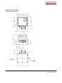
Mechanical specifications, and drawings and measurements of the units Appendix F. Moog Crossbow Service Policies
A summary of customer support services, warranty description, return process and contact information NAV440 User Manual 7430‐0131‐01 Rev. F Page 13
Text Conventions Table 2 Text Conventions Convention Definition Italics
Emphasizes important information, or indicates the title of a document. Bold Stronger emphasis of important information. System items
Indicates a sample of screen output, a command in the body of the document or an example of a command to enter. Command
A software command that must be entered as shown. NOTE: Additional information. CAUTION: The information provided should be followed to prevent damage to the equipment.
WARNING:
The information provided must be followed to prevent physical injury. Glossary Table 3 Glossary Term Definition 6DOF Six Degree of Freedom ACL Accelerometer AHRS Attitude Heading Reference BIT Built In Test DSP Digital Signal Processor ECEF Earth‐Centered Earth‐Fixed ESS Environmental Stress Screening EKF Extended Kalman Filter FIR Finite Impulse Response GB‐GRAM Ground‐Based GPS Receiver Application Module GPS Global Positioning System Hard failure Fatal condition, non‐operational Hard iron Magnetism is retained (permanent) IMU Inertial Measurement Unit LLA Latitude Longitude and Altitude LSB Least Significant Byte MEMS Micro‐Electro‐Mechanical Systems MSB Most Significant Byte NAV440 User Manual
7430‐0131‐01 Rev. F Page 14 Term Definition MTBF Mean Time Between Failure PPS Precise Positioning Service QTP Qualification Test Plan SAASM Selective Availability / Anti‐Spoofing Module SDGPS Satellite Differential GPS Soft error Persistent error, repeated many times within a period of time Soft iron Magnetism is not retained; magnetism only occurs while the material exposed to a magnetic field VDC Voltage Direct Current VG Vertical Gyroscope WAGE Wide Area GPS Enhancement NAV440 User Manual 7430‐0131‐01 Rev. F Page 15
Page 16 NAV440 User Manual
7430‐0131‐01 Rev. F Chapter 1. 440 Series Overview This chapter provides a high level summary of the 440 Series : •
Software Compatibility, page 17 •
440 Series Inertial System Functions, page 17 •
Summary of Major Changes from the 300/400 Series and the 420 Series, page 18 Software Compatibility Moog Crossbow ’s 440 Series Inertial Systems are not software compatible with any previous Moog Crossbow products. The 440 Series units utilize a new extensible communication protocol which is documented in Chapter 9. Communicating with the 440Series Units. Additionally, the 440 Series includes numerous enhancements and features that allow for better performance in many applications than the comparable 400 or 420 Series products. 440Series Inertial System Functions This manual provides a comprehensive introduction to the use of Moog Crossbow ’s 440 Series Inertial System functions listed in Table 4 below. This manual is intended to be used as a detailed technical reference and operating guide for the 440 Series . Moog Crossbow ’s 440 Series units combine the latest in high‐performance commercial MEMS (Micro‐Electromechanical Systems) sensors and digital signal processing techniques to provide a small, cost‐
effective alternative to existing IMU systems and mechanical gyros. Table 4 440 Series Functional Description Function Features IMU440 6‐ DOF Digital IMU VG440 6‐DOF IMU, plus Dynamic Roll/Pitch AHRS440 6‐DOF IMU with 3‐Axis Internal Magnetometer Dynamic Roll, Pitch, and Heading NAV440 6‐DOF IMU with 3‐Axis Internal Magnetometer, and Internal WAAS Capable GPS Receiver Position, Dynamic Velocity, and Dynamic Roll, Pitch, Heading The 440 Series is Moog Crossbow ’s third generation of MEMS‐based Inertial Systems, building on over a decade of field experience, and encompassing thousands of deployed units and millions of operational hours in a wide range of land, marine, airborne, and instrumentation applications. •
At the core of the 440 Series is a rugged 6‐DOF (Degrees of Freedom) MEMS inertial sensor cluster that is common across all members of the 440 Series . The 6‐DOF MEMS inertial sensor cluster includes three axes of MEMS angular rate sensing and three axes of MEMS linear acceleration sensing. These sensors are based on rugged, field proven silicon bulk micromachining technology. Each sensor within the cluster is individually factory calibrated for temperature and non‐linearity effects during Moog Crossbow ’s manufacturing and test process using automated thermal chambers and rate tables. NAV440 User Manual 7430‐0131‐01 Rev. F Page 17
•
Coupled to the 6‐DOF MEMS inertial sensor cluster is a high performance Digital Signal Processor (DSP) that utilizes the inertial sensor measurements to accurately compute navigation information including attitude, heading, and linear velocity thru dynamic maneuvers (actual measurements are a function of the 440 Series unit as shown in Table 2). The DSP processor makes use of internal and external magnetic sensor and/or GPS data to aid the performance of the inertial algorithms and help correct long term drift and estimate errors from the inertial sensors and computations. The navigation algorithm utilizes a multi‐state configurable Extended Kalman Filter (EKF) to correct for drift errors and estimate sensor bias values. This algorithm runs on a 150MHz 32‐bit DSP that has approximately four times the computational power of Moog Crossbow ’s earlier generation Inertial Systems. •
Another unique feature of the 440 Series is the extensive field configurability of the units. This field configurability allows the 440 Series of Inertial Systems to satisfy a wide range of applications and performance requirements with a single mass produced hardware platform. The basic configurability includes parameters such as baud rate, packet type, and update rate, and the advanced configurability includes the defining of custom axes and how the sensor feedback is utilized in the Kalman filter during the navigation process. The 440 Series is packaged in a fully sealed lightweight housing which provides EMI, vibration, and moisture resistance to levels consistent with most land, marine, and airborne environments. The 440 Series utilizes an RS‐
232 serial link for data communication, and each data transmission includes a BIT (Built‐In‐Test) message providing system health status. The 440 Series is supported by Moog Crossbow ’s NAV‐VIEW 2.X, a powerful PC‐based operating tool that provides complete field configuration, diagnostics, charting of sensor performance, and data logging with playback. Summary of Major Changes from the 300/400 Series and the 420 Series Mechanical Size and Footprint The mechanical footprint of Moog Crossbow ’s new 440 Series Inertial Systems is compatible with prior generation Inertial Systems including Moog Crossbow ’s 400 Series (IMU400, VG400, AHRS400) and the NAV420 Series products. The mounting plate foot print is the same and the connector location is identical. The 440 Series units are shorter than their equivalent 400 Series product (i.e. the AHRS440 is shorter than the AHRS400, etc). The 440 Series unit is dimensionally equivalent to the NAV420. For detailed mechanical and installation drawings, refer to Appendix E. Mechanical Specifications. Connector Pin Out & Operating Voltage, Current The DB‐15 male connector on Moog Crossbow ’s 440 Series Inertial Systems has a backward compatible pin out with the 400 Series and 420 Series. However, the 440 Series has a secondary optional‐use communications port for internal or external GPS. Operating Performance and Accuracy The 440 Series has been characterized in a wide range of land and airborne applications. In the qualification testing, the dynamic accuracy of the 440 Series has shown superior performance when compared to the equivalent model of 400 and 420 Series, reducing attitude estimation errors in half during certain critical dynamic maneuvers without the use of GPS aiding. With GPS aiding in the NAV440, attitude estimation is improved by an order of magnitude compared with 400 series products. Recommended configuration settings are discussed in Appendix B. Application Examples. The 440 Series functions are discussed in Chapter 2. 440 Series Functions.
Page 18 NAV440 User Manual
7430‐0131‐01 Rev. F Chapter 2. 440 Series Functions This chapter provides an overview of the hardware and software systems of the 440 Series unit, and the functions provided. •
440 Series System, page 19 •
Software Structure, page 20 •
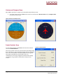
440 Series Default Coordinate System, page 22 •
IMU440 , page 23 •
VG440 (Vertical Gyroscope) , page 25 •
AHRS440 Function, page 27 •
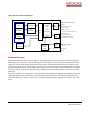
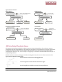
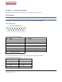
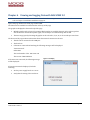
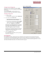
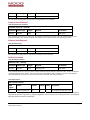
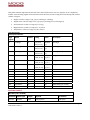
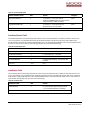
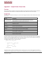
NAV440 Function, page 30 440 Series System The 440 Series is a compact MEMS based GPS/inertial navigation system. It delivers continuous GPS position, true heading and vehicle attitude tracking information for ground tactical vehicles. The system integrates advanced MEMS inertial gyros and accelerometers, embedded or optional remote 3‐axis magnetometer, a SAASM or C/A code GPS receiver, and 10/100 Ethernet interface in a fully sealed enclosure for tactical vehicle operating in combat or homeland security environments. Figure 1 below shows the 440 Series hardware block diagram. At the core of the 440 Series is a rugged 6‐DOF (Degrees of Freedom) MEMS inertial sensor cluster that is common across all members of the 440 Series . The 6‐
DOF MEMS inertial sensor cluster includes three axes of MEMS angular rate sensing and three axes of MEMS linear acceleration sensing. These sensors are based on rugged, field proven silicon bulk micromachining technology. Each sensor within the cluster is individually factory calibrated using Moog Crossbow ’s automated manufacturing process. Configuring GNAV540 Functions Based on the User Behavior settings, the Series 440 unit can be configured to fulfill various functions. 1.
Using only the calibrated sensor data, the Series 440 unit functions as an Inertial Measurement Unit (IMU) to output angular rates and accelerations. 2.
Incorporating the gyroscope and accelerometer data with the EKF, the Series 440 unit can output roll and pitch attitude information, functioning as a Vertical Gyroscope (VG) unit. 3.
Building on the VG function and combining magnetic field measurement, the GNAV540 can function as an Attitude Heading Reference System (AHRS): provide a heading angle estimate in addition to the (VG) roll and pitch. The Series 440 unit is provided with an internal magnetometer; an external magnetometer can be integrated with the unit and configured to override the internal magnetometer. 4.
Combining GPS sensor data into the EKF, the Series 440 unit can provide a complete attitude system, as well as outputting 3D velocity and position measurements, thereby functioning as a Navigation unit (NAV). An internal C/A code GPS receiver is provided; an external WAAS GPS receiver can be integrated with the unit and configured to override the internal receiver. NAV440 User Manual 7430‐0131‐01 Rev. F Page 19
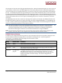
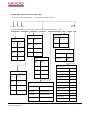
Figure 1 440 Series Hardware Block Diagram System Digital Outputs and Inputs
X/Y/Z
XY / Z
High-Speed
Gyros
Programmable
Sampling &
DSP
X/Y/Z
XYZ
Accelerometers
Programmable
16-BIT
(Pins 1,2)
RS-232
(A Port)
+
X / Y / Z Acceleration
Sensor
Roll / Pitch / Yaw Rate
X / Y / Z Magnetic Fields (NAV/AHRS only)
Compensation
A/D
Roll / Pitch / Yaw Angle
+
Sensor
Temperatures
Moog Crossbow Serial Protocol
Navigation &
Attitude
RS-232
(B Port)
Position / Velocity (NAV only)
Optional use port (Pins 7,8)
External GPS Input (VG/AHRS)
6-DOF Sensor
Cluster
X/Y/Z
Magnetometers
RS-232
GPS Receiver
Internal GPS Output
(NAV)
(B Port)
(WAAS)
NAV only
GPS Antenna
NAV only
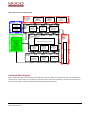
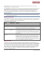
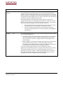
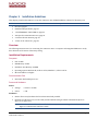
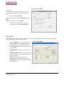
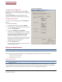
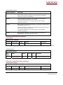
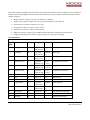
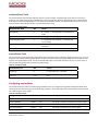
Software Structure Figure2below shows the software block diagram. The 6‐DOF inertial sensor cluster data is fed into a high speed 100Hz signal processing chain. These 6‐DOF signals pass through one or more of the processing blocks and these signals are converted into output measurement data as shown. Measurement data packets are available at fixed continuous output rates or on a polled basis. The type of measurement data packets available depends on the unit type according to the software block diagram and. Aiding sensor data is used by an Extended Kalman Filter (EKF) for drift correction. Built‐In‐Test and Status data is available in the measurement packet or via the special Status Packet T0. As shown in Figure2, the 440 Series has a unit setting and profile block which configures the algorithm to user and application specific needs. This feature is one of the more powerful features in the 440 Series architecture as it allows the 440 Series to work in a wide range of commercial applications by setting specific functions of the 440 Series . Page 20 NAV440 User Manual
7430‐0131‐01 Rev. F Figure 2 440 Series Software Block Diagram Measurement
Data Available to
User (Fixed Rate
or Polled)
IMU - Scaled Packets
(S0,S1,S2)
All Units
NAV/AHRS/VG/IMU
VG/AHRS – Angle
Packets
(A0,A1,A2)
NAV/AHRS/VG
NAV - Nav Packets
(N0,N1)
NAV/AHRS/VG
6-DOF Sensor Cluster
X / Y / Z Body
Rates
100Hz
Signal
Proc.
Chain
X / Y / Z Body
Accelerometers
Unit Settings & Profile*
Integration to
Attitude
Integration to 100 Hz
Velocity, GPS
Position Output
Extended Kalman Filter (EKF)
Drift Correction Module
Built In Test
& Status
Data
Availabe to
User
Communication Settings
Axes Orientation
LowPass Filtering
Free Integrate
UseGPS
UseMags
TurnSwitch Threshold
DynamicMotion
Restart On Overange
Dynamic Motion
Programmable BIT Alerts
Sensor
Calibration
Axes Rotation
Kalman Filter and DynamicState Model
Hard/Soft Iron
Calibration
UseMags
Free Integrate
TurnSwitch
Threshold
UseGPS
Stationary Yaw
Lock
Status Packet (T0)
Aiding Sensors
X/Y/Z
Magnetometers
NAV/AHRS only
Gravity Reference
Turn Rate
(Internal
Computation)
GPS Data
Internal/External
Functional Block Diagram Figure 3below illustrates the unit setting and profile block, which configures the algorithm to user and application specific needs. This feature is one of the more powerful features in the 440 architecture; it allows the 440 Series to work in a wide range of commercial applications by setting specific functions. NAV440 User Manual 7430‐0131‐01 Rev. F Page 21
Figure 3 440 Series Functions NAV Function AHRS Function Attitude and velocity
propagation 100 Hz
∑ accels, rates, MAGS, attitude,
,
velocity, GPS position
Attitude propagation
100 Hz Correction algorithm ,
Correction algorithm Roll/pitch heading velocity
Accelerometer tilt
accels, rates,
mags, attitude,
∑ Magnetometer
heading
Roll/pitch heading velocity
GPS velocity
Accelerometer tilt
Magnetometer
heading
VG Function with External GPS Attitude and velocity
propagation 100 Hz VG Function accels, rates, attitude,
velocity, GPS position
∑ ? Attitude propagation
100 Hz
Correction algorithm
Roll/pitch heading velocity
accels, rates,
attitude,
(heading/yaw free
∑ Correction algorithm Roll/pitch heading velocity
Accelerometer
Accelerometertilt
GPS velocity
Accelerometer tilt
440 Series Default Coordinate System The 440Series Inertial System default coordinate system is shown in Figure4below. The coordinate system is configurable with either NAV‐VIEW 2.2 or by sending the appropriate serial commands. This section of the manual describes the default coordinate system settings of the unit when it leaves the factory. For information about configuring the 440 Series unit, refer to Chapter 7. Configuring the 440 Series with NAV‐VIEW 2.2and Chapter 10. Programming Guidelines. With the 440 Series connector facing you and the mounting plate down, the axes are defined as shown below: Figure 4 440 Series Default Coordinate System Xaxis: from face with connector through the unit Yaxis: along the face with connector from left to right Zaxis: along the face with the connector from top to bottom Page 22 NAV440 User Manual
7430‐0131‐01 Rev. F The axes form an orthogonal SAE right‐handed coordinate system. Acceleration is positive when it is oriented towards the positive side of the coordinate axis. For example, with a 440Series unit sitting on a level table, it will measure zero g along the x and y‐axes and ‐1 g along the z‐axis. Normal Force acceleration is directed upward, which would be defined as negative for the 440 Series z‐axis. The angular rate sensors are aligned with the same axes. The rate sensors measure angular rotation rate around a given axis. The rate measurements are labeled by the appropriate axis. The direction of a positive rotation is defined by the right‐hand rule. With the thumb of your right hand pointing along the axis in a positive direction, your fingers curl around in the positive rotation direction. For example, if the 440Series unit is sitting on a level surface and you rotate it clockwise on that surface, this will be a positive rotation around the z‐axis. The x and y‐axis rate sensors would measure zero angular rates, and the z‐axis sensor would measure a positive angular rate. The magnetic sensors are aligned with the same axes definitions and sign as the linear accelerometers. For example, when oriented towards magnetic North, you will read approximately +0.25 Gauss along X, 0.0 Gauss along Y, and +0.35 Gauss along Z direction (North America). Magnetic values at other geographic locations are available at http://www.ngdc.noaa.gov/geomag/WMM/DoDWMM.shtml. Pitch is defined positive for a positive rotation around the y‐axis (pitch up). Roll is defined as positive for a positive rotation around the x‐axis (roll right). Yaw is defined as positive for a positive rotation around the z‐axis (turn right).The angles are defined as standard Euler angles using a 3‐2‐1 system. To rotate from the body frame to an earth‐level frame, roll first, then pitch, and then yaw. The position output from GPS is represented in Latitude, Longitude, and Altitude (LLA) convention on the WGS84 Ellipsoid. This is the most commonly used spherical coordinate system. The GPS velocity is defined in North, East and Down reference frame, which can be converted to the Cartesian coordinate system: Earth‐Centered, Earth‐Fixed (ECEF). ECEF uses three‐dimensional XYZ coordinates (in meters) to describe the location of a GPS user or satellite. Several online resources are available to help users with this transformation. Application notes are available on the Moog Crossbow website: http://www.moog‐crossbow.com. Advanced Settings The 440Series Inertial Systems have a number of advanced settings that can be changed. The specific settings available vary from unit to unit, and a detailed description of each unit is found in the subsequent sections of this manual. All units support baud rate, power‐up output packet type, output rate, sensor low pass filtering, and custom axes configuration. The units can be configured via two methods: •
NAV‐VIEW 2.2, a GUI application, (Chapter 7. Configuring the 440 Series with NAV‐VIEW 2.2) •
Program commands, Chapter 10. Programming Guidelines) IMU440 Function IMU440 (Inertial Measurement Unit) provides the inertial measurement unit functionality that the unit provides by outputting inertial rate and acceleration data in 6‐DOF (six degrees of freedom). The IMU440 signal processing chain consists of the 6‐DOF sensor cluster, programmable low‐pass filters , analog to digital conversion, and the DSP signal processor for sensor error compensation. The rate and acceleration analog sensor signals are sampled and converted to digital data at 1 kHz. The sensor data is filtered and down‐sampled to 100Hz by the DSP using FIR (finite impulse response) filters. The factory calibration data, stored in EEPROM, is used by the DSP to remove temperature bias, misalignment, scale factor errors, and non‐linearities from the sensor data. Additionally any advanced user settings such as axes rotation are applied to the IMU440 data. The 100Hz IMU440 data is continuously being maintained inside the unit. NAV440 User Manual 7430‐0131‐01 Rev. F Page 23
Digital IMU440 data is output over the RS‐422 at a selectable fixed rate (100, 50, 25, 20, 10, 5 or 2 Hz) or as requested using the GP (Get Packet) command. The digital IMU440 data is available in one of several measurement packet formats including Scaled Sensor Data (S1 Packet) and Delta‐Theta, Delta‐V (S2 Packet). In the Scaled Sensor Data (S1 Packet) data is output in scaled engineering units. In the Delta‐Theta, Delta‐V format (S2 Packet) scaled sensor data is integrated with respect to the time of the last output packet and the data is reported in units of accumulated (i.e., delta) degrees and meters/second. For details about full packets, refer to Chapter 9. Communicating with the 440 and Chapter 10. Programming Guidelines.
NOTE: The Delta‐Theta, Delta‐V packet is only recommended for use in continuous output mode at 5Hz or greater. Polled requests for this packet will produce values accumulated since the last poll request; they are subject to overflow (data type wrap around). IMU440 Advanced Settings The IMU440 advanced settings are described in Table 5below. All of the advanced settings are accessible thru NAV‐
VIEW 2.2 under the Configuration Menu→Unit Configuration settings. For information about using NAV‐VIEW 2.2, refer to Chapter 7. Configuring the 440 Series with NAV‐VIEW 2.2.
Table 5IMU440 Function Advanced Settings Setting Default Value Comments Baud Rate 38,400 9600, 19200, 57600 also available Packet Type S1 S2 also available Packet Rate 100Hz This sets the rate at which the selected Packet Type packets are output. If polled mode is desired, then select Quiet. If Quiet is selected, the unit will only send measurement packets in response to GP commands. Orientation See Figure 4 on page 22. To configure the axis orientation, select the desired measurement for each axis: NAV‐VIEW 2.2 will show the corresponding image of the unit, so it easy to visualize the mode of operation. Refer to Orientation Field on page 84 for the twenty four possible orientation settings. The default setting points the connector AFT. Analog Filter Clocks 1,2, 3 25 Hz The low pass filters are set to a default of 25 Hz for the accelerometers, and 25 Hz for the angular rate sensors. There is one filter setting for all three angular rate sensors. There are two settings for the accelerometers, one for the X and Y axes, and a separate setting for the Z axis. In many installations, the Z‐axis vibration level is much higher than in the X and Y axes; in such cases it can prove helpful to filter the Z‐axis at a lower cutoff than the X and Y axes. For more information, Analog Filter Clocks below. Analog Filter Clocks Typically, there is no reason to change the low‐pass filter settings on the IMU440 or other 440 Series Inertial Systems. However, when a 440 Series unit is installed in an environment with a lot of vibration, it can be helpful to reduce the vibration‐based signal energy and noise prior to further processing on the signal. Installing the IMU440 in the target environment and reviewing the data with NAV‐VIEW 2.X can be helpful to determine if changing the filter settings is needed. Although the filter settings can be helpful in reducing vibration based noise in the signal, low filter settings (e.g., 1Hz) also reduce the bandwidth of the signal, i.e. can wash out the signals containing the dynamics of a target. The analog filter clock settings are shown in default IMU440 coordinate system. Treat the filter settings with caution. Page 24 NAV440 User Manual
7430‐0131‐01 Rev. F NOTE: If the coordinate system is configured to a non‐standard or custom configuration, apply the appropriate rotation and configure the filter settings accordingly. VG440 (Vertical Gyroscope)Function The VG440 provides dynamic roll and pitch measurements, as well as allIMU440 data functions. The dynamic roll and pitch measurements are stabilized by the using the accelerometers as a long‐term gravity reference. The VG440 can also output a free integrating yaw angle measurement that is not stabilized by a magnetometer or compass heading). At a fixed 100Hz rate, the VG440 continuously maintains both the digital IMU440 data as well as the dynamic roll and pitch data. As shown in the software block diagram(Figure 2 on page 21), after the Sensor Calibration block, the IMU440 data is passed into an Integration to Orientation block. (If using external GPS, refer to Figure 4on page22.)The Integration to Orientation block integrates body frame sensed angular rate to orientation at a fixed 100 times per second. For improved accuracy and to avoid singularities when dealing with the cosine rotation matrix, a quaternion formulation is used in the algorithm to provide attitude propagation. Also shown in the software block diagram (Figure 2, page 21) the Integration to Orientation block receives drift corrections from the Extended Kalman Filter or Drift Correction Module. In general, rate sensors and accelerometers suffer from bias drift, misalignment errors, acceleration errors (g‐sensitivity), nonlinearity (square terms), and scale factor errors. The largest error in the orientation propagation is associated with the rate sensor bias terms. The Extended Kalman Filter (EKF) module provides an on‐the‐fly calibration for drift errors, including the rate sensor bias, by providing corrections to the Integration to Orientation block and a characterization of the gyroscope bias state. In the VG440, the internally computed gravity reference vector provides a reference measurement for the EKF when the unit is in quasi‐static motion to correct roll and pitch angle drift and to estimate the X and Y gyroscope rate bias. Because the gravity vector has no horizontal component, the EKF has no ability to estimate either the yaw angle error or the Z gyroscope rate bias. VG440 adaptively tunes the EKF feedback in order to best balance the bias estimation and attitude correction with distortion free performance during dynamics when the object is accelerating either linearly (speed changes) or centripetally (false gravity forces from turns). Because centripetal and other dynamic accelerations are often associated with yaw rate, the unit maintains a low‐pass filtered yaw rate signal and compares it to the turnSwitch threshold field (user adjustable). When the platform the unit is attached to exceeds the turnSwitch threshold yaw rate, the unit lowers the feedback gains from the accelerometers to allow the attitude estimate to coast through the dynamic situation with primary reliance on angular rate sensors. This situation is indicated by the softwareStatus→turnSwitch status flag. Using the turnSwitch maintains better attitude accuracy during short‐term dynamic situations, but care must be taken to ensure that the duty cycle of the turnSwitch generally stays below 10% during the vehicle mission. A high turnSwitch duty cycle does not allow the system to apply enough rate sensor bias correction and could allow the attitude estimate to become unstable. The VG440 algorithm has two major phases of operation. The first phase of operation is the initialization phase. During the initialization phase, the unit is expected to be stationary or quasi‐static so the EKF weights the accelerometer gravity reference heavily in order to rapidly estimate the roll and pitch angles, and X, Y rate sensor bias. The initialization phase lasts approximately 60 seconds, and the initialization phase can be monitored in the software Status BIT transmitted by default in each measurement packet. After the initialization phase, the unit operates with lower levels of feedback (also referred to as EKF gain) from the accelerometers to continuously estimate and correct for roll and pitch errors, as well as to estimate X and Y rate sensor bias. To reset the algorithm or re‐enter the initialization phase, sending the algorithm reset command, AR, will force the algorithm into the reset phase. NAV440 User Manual 7430‐0131‐01 Rev. F Page 25
In addition to the scaled sensor packets described in the IMU440 section, the VG440 has additional measurement output packets including the default A2 Angle Packet which outputs the roll angle, pitch angle, and digital IMU440 data. N0 and N1 packets are also available for use with an external GPS receiver. Refer to Chapter 9. Communicating with the 440and Chapter 10. Guidelines for full packet descriptions. VG440 Advanced Settings In addition to the configurable baud rate, packet rate, axis orientation, and sensor low‐pass filter settings, VG440 provides additional advanced settings that are selectable for tailoring the unit to a specific application requirements. The settings are listed in Table 6below. Table 6VG440 Advanced Settings Setting Default Value Comments Baud Rate 38,400 baud 9600, 19200, 57600 also available Packet Type A2 S1, S2, N0, N1 also available Packet Rate 25Hz This setting sets the rate at which selected Packet Type, packets are output. If polled mode is desired, then select Quiet. If Quiet is selected, the unit will only send measurement packets in response to GP commands. Orientation See Figure 4 on To configure the axis orientation, select the desired measurement for each axis: page 22. NAV‐VIEW 2.2 will show the corresponding image of the unit, so it easy to visualize the mode of operation. Refer to Orientation Field on page 84 for the twenty four possible orientation settings. The default setting points the connector AFT. Freely Integrate OFF The Freely Integrate setting allows configuring the unit into a free gyroscope. In free gyroscope mode, the roll, pitch and yaw are computed exclusively from angular rate with no Kalman filter based corrections of roll, pitch, or yaw. When turned on, there is no coupling of acceleration based signals into the roll and pitch. As a result, the roll, pitch, and yaw outputs will drift roughly linearly with time due to sensor bias. For best performance, the Freely Integrate mode should be used after the algorithm has initialized. This allows the Kalman Filter to estimate the roll and pitch rate sensor bias prior to entering the free gyroscope mode. Exiting the free gyroscope mode (OFF), causes one of the following behaviors to occur: • If the unit has been in freely integrate mode for less than sixty seconds, the algorithm will resume operation at normal gain settings. • If the unit has been in freely integrate mode for greater than sixty seconds, the algorithm will force a reset and reinitialize with high gains automatically. Page 26 NAV440 User Manual
7430‐0131‐01 Rev. F Setting Default Value Comments Restart On Over Range OFF This setting forces an algorithm reset when a sensor over range occurs i.e., a rotational rate on any of the three axes exceeds the maximum range. The default setting is OFF. Algorithm reset returns the unit to a high gain state, where the unit rapidly estimates the gyroscope bias and uses the accelerometer feedback heavily. This setting is recommended when the source of over‐range is likely to be sustained and potentially much greater than the rate sensor operating limit. Large and sustained angular rate over‐ranges result in unrecoverable errors in roll and pitch outputs. An unrecoverable error is one where the EKF cannot stabilize the resulting roll and pitch reading. If the over‐ranges are expected to be of short duration (<1 sec) and a modest percentage over the maximum operating range, it is recommended that the restart on over range setting be turned off. Handling an inertial rate sensor over‐range is controlled with the restartOnOverRange switch. • If restartOnOverRangeis off, the system will flag the overRange status flag and continue to operate through it. • If restartOnOverRangeis on, the system will flag a master Fail error during an over‐range condition and continue to operate with this flag until a quasi‐
static condition is met to allow for an algorithm restart. The quasi‐static condition required is that the absolute value of each low‐pass rate sensor falls below 3 deg/sec to begin initialization. The system will then attempt a normal algorithm start. Dynamic Motion ON The default setting is ON. Turning off the dynamic motion setting results in a higher gain state that uses the accelerometer feedback heavily. During periods of time when there is known low dynamic acceleration, this switch can be turned off to allow the attitude estimate to quickly stabilize. Turn Switch threshold 10.0 deg/sec With respect to centripetal or false gravity forces from turning dynamics (or coordinated turn), the unit monitors the yaw‐rate. If the yaw rate exceeds a given turnSwitch threshold, the feedback gains from the accelerometer signals for attitude correction are reduced because they are likely corrupted. AHRS440 Function The AHRS440 (Attitude Heading Reference System) unit includes an additional internal 3‐axis magnetometer and associated software running on the DSP processor. This enables the computation of dynamic heading, as well as dynamic roll and pitch. AHRS440 data provides dynamic heading, roll, and pitch measurements, in addition to the VG440 and IMU440 data. The dynamic heading measurement is stabilized using the 3‐axis magnetometer as a magnetic north reference. The dynamic roll and pitch measurements are stabilized using the accelerometers as a long‐term gravity reference. The unit can be configured to turn on and off the magnetic reference for user defined periods of time. This function utilizes data from calibrated sensors, the gyroscopes, the accelerometers and a magnetometer (internal or external). For details of the IMU functions, refer to IMU440 Function on page 23. For details of the VG functions, refer to VG440 (Vertical Gyroscope) Function), on page 25.In addition to those features, the AHRS440 algorithm has two major phases of operation. NAV440 User Manual 7430‐0131‐01 Rev. F Page 27
The first phase of operation is the high‐gain initialization phase. During the initialization phase, the unit is expected to be stationary or quasi‐static so the EKF weights the accelerometer gravity reference and Earth’s magnetic field reference heavily in order to rapidly estimate the X, Y, and Z rate sensor bias, and the initial attitude and heading of the unit. The initialization phase lasts approximately 60 seconds, and the initialization phase can be monitored in the software Status BIT transmitted by default in each measurement packet. After the initialization phase, the unit operates with lower levels of feedback (also referred to as EKF gain) from the accelerometers and magnetometers to continuously estimate and correct for roll, pitch, and heading (yaw) errors, as well as to estimate X, Y, and Z rate sensor bias. The AHRS440provides the same scaled sensor and angle mode packets of the VG440. The AHRS440 defaults to the A1 Angle Packet which outputs the roll angle, pitch angle, yaw angle, and digital IMU440data. In the AHRS440, the A0 and A1 packets contain accurate magnetometer readings. Refer to Chapter 9. Communicating with the 440 and Chapter 10. Programming Guidelines for full packet descriptions. NOTE: For proper operation, the unit relies on magnetic field readings from its internal 3‐axis magnetometer. The unit must be installed correctly and calibrated for hard‐iron and soft iron effects to avoid any system performance degradation. Refer to Chapter 4. Magnetometer Calibration and Alignment Guidelines for information about magnetic calibration; review that information before using the AHRS440. NOTE: The unit must be mounted at least 24” away from large ferrous objects and fluctuating magnetic fields. Failure to locate the unit in a clean magnetic environment will affect the attitude solution. AHRS440 Advanced Settings In addition to the configurable baud rate, packet rate, axis orientation, and sensor low‐pass filter settings, the unit provides additional advanced settings which are selectable for tailoring the unit to specific application requirements. The AHRS440 advanced settings are listed in Table 7 below: Table 7AHRS 440 Series Advanced Settings Setting Default Value Comments Baud Rate 38400 9600, 19200, 57600 also available Packet Type A1 S0, S1, S2, A0, A2, N0, N1 also available Packet Rate 25 Hz This setting sets the rate at which selected Packet Type, packets are output. If polled mode is desired, then select Quiet. Orientation See Figure 4 on To configure the axis orientation, select the desired measurement for each axis: NAV‐VIEW 2.2 will show the corresponding image of the unit, so it easy to page 22. visualize the mode of operation. Refer to Orientation Field on page 84 for the twenty four possible orientation settings. The default setting points the connector AFT. Page 28 NAV440 User Manual
7430‐0131‐01 Rev. F Setting Default Value Comments Freely Integrate OFF The Freely Integrate setting allows a user to turn the unit into a free gyroscope. In free gyroscope mode, the roll, pitch and yaw are computed exclusively from angular rate with no Kalman filter based corrections of roll, pitch, or yaw. When turned on, there is no coupling of acceleration based signals into the roll and pitch or magnetometer based signals to the yaw. Due to sensor bias., the roll, pitch, and yaw outputs will drift roughly linearly with time. For best performance, the Freely Integrate mode should be used after the algorithm has initialized. This allows the Kalman Filter to estimate the roll and pitch rate sensor bias prior to entering the free gyroscope mode. Upon exiting the free gyroscope mode (OFF), one of two behaviors will occur: • If the unit has been in freely integrate mode for less than sixty seconds, the algorithm will resume operation at normal gain settings • If the unit has been in freely integrate mode for greater than sixty seconds, the algorithm will force a reset and reinitialize with high gains automatically. Use Mags ON The Use Mags setting allows users to turn on and off the magnetometer feedback for yaw/heading stabilization. • The default setting is ON. When Use Mags is turned ON, the 440 Series unit uses the magnetic field sensor readings to stabilize the drift in yaw, and it slaves the yaw to the compass reading provided from the magnetic field sensor readings. • When Use Mags is turned OFF, the heading (yaw) angle measurement of the unit will drift and freely integrate. In effect, this setting converts the functionality to VG. However, unlike a unit in the VG440, this can be done on a selectable basis and changed in real time during a mission. The reason for this setting is to give the user an ability to turn off the magnetometer stabilization when severe magnetic distortion may be occurring. This setting is desirable when the user system temporarily moves in close proximity to a large ferrous object. When the Use Mags switch is turned from OFF to ON, the unit will reinitialize the yaw/heading angle with the compass reading provided from the magnetic field sensor readings. NAV440 User Manual 7430‐0131‐01 Rev. F Page 29
Setting Default Value Comments Restart On Over Range OFF This setting forces an algorithm reset when a sensor over range occurs i.e., a rotational rate on any of the three axes exceeds the maximum range. The default setting is OFF. Algorithm reset returns the unit to a high gain state, where the unit rapidly estimates the gyroscope bias and uses the accelerometer feedback heavily. This setting is recommended when the source of over‐range is likely to be sustained and potentially much greater than the rate sensor operating limit. Large and sustained angular rate over‐ranges result in unrecoverable errors in roll and pitch outputs. An unrecoverable error is one where the EKF cannot stabilize the resulting roll and pitch reading. If the over‐ranges are expected to be of short duration (<1 sec) and a modest percentage over the maximum operating range, it is recommended that the restart on over range setting be turned off. Handling of an inertial rate sensor over‐range is controlled using the restartOnOverRange switch. If this switch is off, the system will flag the overRange status flag and continue to operate through it. If this switch is on, the system will flag a masterFail error during an over‐range condition and continue to operate with this flag until a quasi‐static condition is met to allow for an algorithm restart. The quasi‐static condition required is that the absolute value of each low‐pass rate sensor falls below 3 deg/sec to begin initialization. The system will then attempt a normal algorithm start. Dynamic Motion ON The default setting is ON. Turning off the dynamic motion setting results in a higher gain state that uses the accelerometer feedback heavily. During periods of time when there is known low dynamic acceleration, this switch can be turned off to allow the attitude estimate to quickly stabilize. Turn Switch threshold 0.5 deg/sec With respect to centripetal or false gravity forces from turning dynamics (or coordinated turn), the unit monitors the yaw‐rate. If the yaw rate exceeds a given TurnSwitch threshold, the feedback gains from the accelerometer signals for attitude correction are reduced because they are likely corrupted. NAV440Function The NAV Function supports all the features of the IMU440, VG440 and AHRS440 functions. In addition, the NAV function provides an internal GPS receiver, which includes software running on the DSP processor for computing navigation and orientation information. In this function, the unit outputs GPS information (Latitude, Longitude, and Altitude), inertial‐aided 3‐axis velocity information, as well as heading, roll, and pitch measurements, in addition to digital IMU440 data. At a fixed 100Hz rate, the unit continuously maintains the digital IMU440 data; the dynamic roll, pitch, and heading data; as well as the navigation data. As shown in Figure 2 on page 21, after the Sensor Calibration block, the IMU440 data is passed into an Integration to Orientation block. The Integration to Orientation block integrates body frame sensed angular rate to orientation at a fixed 100 times per second. For improved accuracy and to avoid singularities when dealing with the cosine rotation matrix, a quaternion formulation is used in the algorithm to provide attitude propagation. Following the integration to orientation block, the body frame accelerometer signals are rotated into the NED level frame and are integrated to velocity. At this point, the data is blended with GPS position data, and output as a complete navigation solution. Page 30 NAV440 User Manual
7430‐0131‐01 Rev. F As shown in Figure 2 on page 21, the Integration to Orientation and the Integration to Velocity signal processing blocks receive drift corrections from the Extended Kalman Filter (EKF) drift correction module. The drift correction module uses data from the aiding sensors, when they are available, to correct the errors in the velocity, attitude, and heading outputs. Additionally, when aiding sensors are available corrections to the rate gyroscope and accelerometers are performed. The NAV Function blends GPS derived heading and accelerometer measurements into the EKF update depending on the health and status of the associated sensors. If the GPS link is lost or poor, the Kalman Filter solution stops tracking accelerometer bias, but the algorithm continues to apply gyroscope bias correction and provides stabilized angle outputs. The EKF tracking states are reduced to angles and gyroscope bias only. The accelerometers will continue to integrate velocity, however, accelerometer noise, bias, and attitude error will cause the velocity estimates to start drifting within a few seconds. The attitude tracking performance will degrade, the heading will freely drift, and the filter will revert toVG440 functions: the EKF formulation will continue without GPS velocity. The UTC packet synchronization will drift due to internal clock drift. The status of GPS signal acquisition can be monitored from the hardware Status BIT (refer to in Chapter 11. Built In Test (BIT)). From a cold start, it typically takes 40 seconds for GPS to lock. The actual lock time depends on the antenna’s view of the sky and the number of satellites in view. The DSP performs time‐triggered trajectory propagation at 100Hz and synchronizes the sensor sampling with the GPS UTC (Universal Coordinated Time) second boundary when available. As with the AHRS440and VG440, the algorithm has two major phases of operation. Immediately after power‐up, the unit uses the accelerometers and magnetometers to compute the initial roll, pitch and yaw angles. The roll and pitch attitude will be initialized using the accelerometer’s reference of gravity, and yaw will be initialized using the leveled magnetometers X and Y axis reference of the earth’s magnetic field. During the first 60 seconds of startup, the unit should remain approximately motionless in order to properly initialize the rate sensor bias. The initialization phase lasts approximately 60 seconds, and the initialization phase can be monitored in the software Status BIT transmitted by default in each measurement packet. After the initialization phase, the unit operates with lower levels of feedback (also referred to as EKF gain) from the GPS, accelerometers, and magnetometers. The NAV Function provides additional output measurement packets including the default N1 Navigation Packet, which outputs the Latitude, Longitude, Altitude, X,Y,Z velocities, accelerations, and roll angle, pitch angle, yaw angle, and digital IMU440 data. Refer to Chapter 9. Communicating with the 440andChapter 10. Programming Guidelines for full packet descriptions. NAV440Advanced Settings In addition to the configurable baud rate, packet rate, axis orientation, and sensor low‐pass filter settings, the NAV Function provides additional advanced settings, which are selectable for tailoring the unit to a specific application requirements. The advanced settings are listed in Table 8 NAV440 Advanced Settings below: Table 8NAV440 Advanced Settings Setting Default Value Comments Baud Rate 38400 9600, 19200, 57600 also available Packet Type N1 S0, S1, S2, A0, A1, A2, N0 also available Packet Rate 25 Hz This setting sets the rate at which selected Packet Type, packets are output. If polled mode is desired, then select Quiet. NAV440 User Manual 7430‐0131‐01 Rev. F Page 31
Setting Default Value Comments Orientation See Figure 4on page 22. To configure the axis orientation, select the desired measurement for each axis: NAV‐VIEW 2.2 will show the corresponding image of the unit, so it easy to visualize the mode of operation. Refer to Orientation Field on page 84 for the twenty four possible orientation settings. The default setting points the connector AFT. Freely Integrate OFF The Freely Integrate setting allows a user to turn the unit into a free gyroscope. In free gyroscope mode, the roll, pitch and yaw are computed exclusively from angular rate with no Kalman filter based corrections of roll, pitch, and yaw. When turned on, there is no coupling of acceleration based signals into the roll and pitch or magnetometer based signal to the yaw. As a result, the roll, pitch, and yaw outputs will drift roughly linearly with time due to sensor bias. For best performance, the Freely Integrate mode should be used after the algorithm has initialized. This allows the Kalman Filter to estimate the roll and pitch rate sensor bias prior to entering the free gyroscope mode. Upon exiting the free gyroscope mode (OFF), one of two behaviors will occur If the unit has been in freely integrate mode for less than sixty seconds, the algorithm will resume operation at normal gain settings If the unit has been in freely integrate mode for greater than sixty seconds, the algorithm will force a reset and reinitialize with high gains automatically. Use GPS ON The Use GPS setting allows users to turn on and off the GPS feedback. The default setting is ON. When Use GPS is turned OFF, the units behavior will revert to AHRS440. Stationary Yaw Lock OFF This setting defaults to OFF; it is recommended to be OFF for NAV Function. The stationary yaw lock is only recommended for consideration when the unit is operating with GPS (Use GPS = ON) and WITHOUT magnetometer feedback (UseMags = OFF). Stationary yaw lock may be appropriate if the user platform is a ground vehicle. Use Mags ON The Use Mags setting allows users to turn on and off the magnetometer feedback for yaw/heading stabilization. The default setting is ON.. When Use Mags is turned ON, the unit uses the magnetic field sensor readings to stabilize the drift in yaw, and it slaves the yaw to the compass reading provided from the magnetic field sensor readings. When UseMags is turned OFF, the heading (yaw) angle measurement of the unit will be slaved to the GPS heading if GPS is available, otherwise the heading will drift feely. The reason for this setting is to give the user an ability to turn off the magnetometer stabilization when severe magnetic distortion may be occurring. This setting is desirable when the user vehicle temporarily moves in close proximity to a large ferrous object. When the UseMags switch is turned from OFF to ON, the unit will reinitialize the yaw/heading angle with the compass reading provided from the magnetic field sensor readings. Page 32 NAV440 User Manual
7430‐0131‐01 Rev. F Setting Default Value Comments Restart On Over Range OFF This setting forces an algorithm reset when a sensor over range occurs i.e., a rotational rate on any of the three axes exceeds the maximum range. The default setting is OFF.. Algorithm reset returns the unit to a high gain state, where the unit rapidly estimates the gyroscope bias and uses the accelerometer feedback heavily. This setting is recommended when the source of over‐range is likely to be sustained and potentially much greater than the rate sensor operating limit. Large and sustained angular rate over‐ranges result in unrecoverable errors in roll and pitch outputs. An unrecoverable error is one where the EKF cannot stabilize the resulting roll and pitch reading. If the over‐ranges are expected to be of short duration (<1 sec) and a modest percentage over the maximum operating range, it is recommended that the restart on over range setting be turned off. Handling of an inertial rate sensor over‐range is controlled using the restartOnOverRange switch. If this switch is off, the system will flag the overRange status flag and continue to operate through it. If this switch is on, the system will flag a masterFail error during an over‐
range condition and continue to operate with this flag until a quasi‐static condition is met to allow for an algorithm restart. The quasi‐static condition required is that the absolute value of each low‐pass rate sensor falls below 3 deg/sec to begin initialization. The system will then attempt a normal algorithm start. Dynamic Motion ON The default setting is ON. Turning off the dynamic motion setting results in a higher gain state that uses the accelerometer feedback heavily. During periods of time when there is known low dynamic acceleration Turn Switch threshold 0.5 deg/sec With respect to centripetal or false gravity forces from turning dynamics (or coordinated turn) NAV440 User Manual 7430‐0131‐01 Rev. F Page 33
Page 34 NAV440 User Manual
7430‐0131‐01 Rev. F Chapter 3. Hardware Interface This chapter provides information about the power and signal interface connectors. I/O Connector NOTE: During the normal operation of the 440 Series , do not connect to the factory test pins: 6, 12 14, 15. These pins have internal pull‐up mechanisms and must have no connections for the 440 Series to operate properly. The 440 Series has a male DB‐15 connector. The signals are as shown in Table 3 below. Figure 5 DB15 Connector Table 3 DB‐15 Connector Pin Assignments Pin Signal Pin Signal 1 RS‐232 Transmit Data (A Port) 9 Signal Ground 2 RS‐232 Receive Data (A Port) 10 1 PPS OUT 3 Positive Power Input (+Vcc) 11 1 PPS (IMU440/VG440/AHRS440 only) 4 Power Ground 12 NC – factory use only 5 Chassis Ground 13 Hardware BIT Error 6 NC – Factory use only 14 NC – factory use only 7 RS‐232 GPS Tx (B Port) 15 NC – factory use only 8 RS‐232 GPS Rx (B Port) For a standard DB‐9 COM port connector, connect the signals as listed below in Table 10. Table 9 DB‐9 COM Port Pin Assignments COM Port Connector
440 Series Connector
Pin # Signal Pin # Signal 2 RxD 1 TxD 3 TxD 2 RxD 5 GND 9 GND NAV440 User Manual 7430‐0131‐01 Rev. F Page 35
J2—GPS Antenna Connector The GPS receiver needs to receive signals from as many satellites as possible. A GPS receiver does not work properly in narrow streets and underground parking lots or if objects or human beings cover the antenna. Poor visibility may result in position drift or a prolonged Time‐To‐First‐Fix (TTFF). A good sky visibility is therefore a prerequisite. Even the best receiver cannot compensate for signal loss due to a poor antenna, in‐band jamming or a poor RF cable. The unit ships with an external active antenna that must be connected properly to SMA jack on the unit case. Placing the antenna on a 16 square inch or larger ground plane is highly recommended. I/O Port Interface Port A: User (computer), RS232 serial data interface The serial interface is standard RS‐232, 9600, 19200, 38400, or 57600 baud, 8 data bits, 1 start bit, 1 stop bit, no parity, and no flow control and will output at a user configurable output rate. These settings allow interaction via a standard PC serial port. Port B: GPS Interface, RS232 serial interface Port B can be applied to internal or external GPS interface. Internal GPS The internal GPS receiver of the NAV440 outputs data in NMEA‐0183 format as defined by the National Marine Electronics Association (NMEA), Standard For Interfacing Marine Electronic Devices, Version 2.20, January 1, 1997. The packets are sent at 9600 Baud, 8 data bits, 1 start bit, 1 stop bit, no parity bit, and no flow control. GPS messages are delivered in NMEA message format. For more information, refer to Appendix A. NMEA Message Format on page 103. External GPS External GPS is supported via VG440 and AHRS440 functions. For the 440 Series unit to interface with an external GPS receiver, the GPS receiver must be configured to output data in a format compatible with the 440 Series unit. Formats are described in the next section: External GPS Aiding (Port B, VG440 and AHRS440) on page 37. Cable Field Requirements The 440 Series is shipped with an EMI filter attached to the DB‐15 Connector. This connector must remain in place to ensure proper shielding from EMI interference. CAUTION: The cable sent with the unit is intended to provide the user with the ability to test the unit right out of the box, and will not provide adequate shielding for all environments. Case ground must be used to provide full EMI protection, and ensure the cable shield is grounded on only one end of the cable. Case Grounding The case is electrically connected to Pin 5 of the DB‐15 connector. The Pin 5 should be electrically connected to the user’s cable shield, especially if the chassis does not make good ground contact. The case should be bolted to a good conducting surface that is grounded. Page 36 NAV440 User Manual
7430‐0131‐01 Rev. F Signals External GPS Aiding (Port B, VG440 and AHRS440) NOTE: This feature only applies to VG440 and AHRS440. NOTE: The GPS serial communication port should be configured to 8 data bits, 1 start bit, 1 stop bit, no parity bit, and no flow control. The VG440/AHRS440 allows using an external GPS receiver. To do so, the following actions are required: •
The external GPS receiver must be configured to output the GPS messages to be compatible with the 440 Series . Table 10 below shows the supported GPS protocols and guidelines for configuration. The details of the GPS messages can be found in the respective GPS protocol documents. •
The VG/AHRS440 must be configured to accept external GPS information. Refer to Table 10 below and Chapter 7. Configuring the 440 Series with NAVVIEW 2.2. Table 10 Configuration for External GPS Receiver for VG440/AHRS440 Protocols Required Messages Required Message Rate Baud rate Ublox binary NAV‐LLH, NAV‐VELNED, NAV‐STATUS 4 Hz 9600, 19200, 38400, 57600$
NovAtel OEM4 and OEMV Binary BestPosB, BestVelB 4Hz 9600, 19200, 38400, 57600$
NovAtel OEM4 ASCII PosVelNavDopA 4Hz 19200, 38400, 57600$
NMEA* GPGGA, GPVTG 4Hz 9600, 19200, 38400, 57600$
*Not recommended for airborne applications. $
57600 is the preferred baud rate for optimum performance
If the VG/AHRS440 is parsing valid external GPS data and the GPS receiver has 3D lock, then the comStatusÆnoExternalGPS flag will be zero, otherwise it will be one. Refer to Chapter 11. Built In Test (BIT) on page 93 for details about system status indications. As the NMEA protocol does not provide vertical velocity, the vertical velocity the 440 Series estimates (based upon GPS altitude changes) may not be sufficient for airborne applications. NOTE: The NMEA protocol is not recommended for airborne applications Hardware BIT Error Output The hardware BIT error output pin is the ultimate indication of system failure. This indication is available in most software output packets as the master Fail flag. It is the logical AND of the hardware Error, com Error, and software Error flags monitored by the system. In the event of a communication failure, the hardware BIT error pin may be used to detect a master Fail assertion. This pin is open‐collector and requires a 1k to 10k ohm pull‐up resister. The system will drive this pin low to assert a system failure. NAV440 User Manual 7430‐0131‐01 Rev. F Page 37
1 PPS Input Interface The 1PPS input signal allows the user of the 440 Series unit to force synchronization of sensor data collection to a 1Hz rising‐edge signal. The signal must maintain 0.0‐0.2 V zero logic and 3.0‐5.0 volts high logic and stay within 100ms of the internal system 1 second timing. Sending this signal to the system will align the sensor data collection and algorithm processing to its rising edge and 10ms boundaries thereafter. When the system is synchronized to 1PPS, the hardwareStatusÆunlocked1PPS flag will be zero; otherwise, the flag will be one. 1 PPS Output Interface The 1PPS output signal is provided by the internal GPS receiver (when GPS timing is known) on the 440 Series unit. The 1PPS output signal is open‐collector and should be interfaced to a rising‐edge trigger with pull up resistor between 1k and 10k ohms. The 440 Series unit synchronizes sensor data collection to this 1PPS signal internally when available. Therefore, the 100Hz navigation algorithm will run exactly 100 times each second with no slip when locked to 1PPS. Packet data is valid on the rising edge of 1PPS and 10ms boundaries thereafter. There is, however, up to 500µs of additional latency in sensor data collection. If 1PPS is provided by the internal GPS receiver in 440 units, then the rising edge of 1PPS will correspond to the UTC second boundary. When the system is synchronized to 1PPS, the hardware StatusÆunlocked1PPS flag will be zero; otherwise, the flag will be one. Figure 6 below shows the sequential order of the signal present at 1 PPS OUT pin. The one PPS signal is aligned to the sampling clock of 23.104 MHz, which results in the timing resolution of 43 ns. Figure 6 1PPS Output Signal Page 38 NAV440 User Manual
7430‐0131‐01 Rev. F Chapter 4. Magnetometer Calibration and Alignment Guidelines This chapter provides information for calibrating and aligning the magnetometer with the 440 Series unit. •
Compensation for Magnetic Fields, page 39 •
Magnetometer Alignment Using NAV‐VIEW 2.2, page 39 •
Magnetometer Alignment Using Code, page 40 •
Installation Guidelines, page 40 This section provides guidelines to calibrate and align the magnetometer. This information applies when implementing AHRS Function or NAV Function (AHRS440 Function on page 27, NAV440 Function on page 30). NOTE: For effective calibration results, the 440 Series unit must be installed in the system during the alignment process.. If calibrated outside of the system, the magnetism of the system will not be measured. Without those values, the unit will not be able to compensate magnetic readings: either heading readings will be incorrect or error messages will be displayed. Compensation for Magnetic Fields Magnetic sensors measure magnetic fields which are then used to compute heading. A correct heading angle is based only on the earth’s magnetic field. However, the magnetic fields of the NAV440 unit and the surroundings (such as the system/vehicle in which the unit is installed) are also measured, which affect the magnetic reading. To compensate for these magnetic fields and ensure accurate heading readings, the 440 Series unit must be calibrated. The 440 Series unit compensates for the extra magnetic field(s) by taking a series of measurements and then applying those measurements to a two‐dimensional algorithm. The algorithm is used to calculate the hard iron and soft iron effects, the values of which are then stored as constants in the EEPROM of the unit. Those constants are used for correcting the magnetic readings, ensuring accurate heading output. Hard iron effects are shifts in the magnetic fields from ferrous objects or other magnetic material in the proximity of the magnetic sensor. Soft iron effects are the change of direction of a magnetic field; this change is caused by hard iron on the input direction. Hard iron magnetic fields are permanent whereas soft iron magnetic fields are temporary: soft iron can be magnetized and then demagnetized or have varying effects during operation. Following is an overview of the calibration process: 1.
Install the 440 Series in the system (vehicle) in which it will be used 2.
Select an appropriate test location, free of magnetic interference 3.
Run the calibration and alignment procedure 4.
Set the calibration readings in the 440 Series unit NOTE: Ensure the test location is appropriate for magnetic calibration. The calibration process provides corrections for magnetic fields from fixed locations that are relative to the position of the unit. The calibration does not compensate for time varying fields, or fields created by magnetic material that moves relative to the 440 Series unit. Magnetometer Alignment Using NAV‐VIEW 2.2 During the calibration procedure, the unit makes a series of measurements while the user system is being turned through a complete 360 degree circle. A 360 degree rotation gives the unit visibility to hard and soft iron distortion NAV440 User Manual Page 39
7430‐0131‐01 Rev. F in the horizontal plane. Using NAV‐VIEW 2.2, the hard and soft iron effects can be viewed by selecting the Misalignment option on the Configuration Menu, and viewing the magnetic circle during the calibration. For calibration instructions, refer to Aligning the Magnetometer on page 55. Magnetometer Alignment Using Code The unit provides a command interface for initiating the hard iron/soft iron calibration without using NAV‐VIEW 2.2. To do so, send a WC command to initiate the calibration, and then rotate the user system 360 degrees. The WC command has two options: auto‐termination and manual termination. •
With auto‐termination, the unit tracks the yaw movement and after 380 degrees of rotation returns the calibration complete response, CC. The auto‐termination sequence can falsely terminate if the 360 degree rotation is not completed within two (2) minutes of the WC command initiation. •
Manual termination requires sending a second WC command with the termination code in the payload. Manual termination is a good option when the user system moves very slowly (e.g., large marine vessel) and completing the 360 degree rotation may require more than two minutes. The status of the magnetometer calibration is indicated by the softwareErrorÆdataErrorÆmagAlignOutOfBounds error flag available in the T0 packet. You can access the hardIronScaleRatio and softIronScaleRatio calibration data as configuration fields in NAV‐VIEW 2.2, or by using the communication protocol. Also, the softwareError bit of the masterFail byte within the BIT word is transmitted in every measurement packet. When the unit has not been properly calibrated, this softwareError bit will be set to fail (high). The calibration complete (CC) command response message contains the X and Y hard iron bias, as well as the soft iron ratio. This information can be interpreted to give an indication of the quality of the calibration. For more information on the hard iron bias and soft iron ratio, refer to Compensation for Magnetic Fields on page 39. Refer to Chapter 9. Communicating with the 440 for details of the WC and CC commands. Installation Guidelines Field Installation •
For a proper calibration and alignment, the 440 Series unit must be installed in its operating environment, such as the land vehicle or aircraft in which it will be used. Page 40 NAV440 User Manual
7430‐0131‐01 Rev. F Chapter 5. Installation Guidelines This chapter provides information to set up the 440 Series unit and NAV‐VIEW 2.2 software for laboratory test. NOTE: Directions to install a unit in a vehicle for field use is outside the scope of this document. •
Overview, page41 •
Installation Requirements, page 41 •
1. Install Software—NAV‐VIEW 2.2, page 42 •
2.Prepare the Communication Port, page 42 •
3. Connect the GPS Antenna, page 42 •
4. Turn on the 440 Series , page 42 Overview The following instructions are for connecting the 440 Series unit to a computer and using NAV‐VIEW 2.2 to verify basic functions of the unit in a laboratory setting. Installation Requirements Computer •
CPU: ≥ 1GHz •
RAM Memory: ≥ 3GB •
Hard Drive Free Memory: ≥ 60MB •
Operating System: Windows XP, 32 bit or 64 bit; Windows 7, 32 bit or 64 bit •
Microsoft .NET 4.0 or higher Communication Port •
Determine which COM port to use. Power and Hardware Power: •
Voltage: +9 VDC to +42 VDC •
Power: > 5 W Hardware: •
Ensure all necessary hardware has been determined and provided. •
Optional: For laboratory test, use the cable provided with the Moog Crossbow evaluation kit. (Refer to Figure 27 on page 124.) NOTE: The evaluation kit cable is only suitable for laboratory test; it is not designed for field use. Refer to Figure 27 Evaluation Kit 440 Series Cable
NAV440 User Manual 7430‐0131‐01 Rev. F Page 41
1. InstallSoftware—NAV‐VIEW 2.2 Instructions a.
Insert the CD 440 Series Inertial System in the CD‐ROM drive. b.
On the CD, navigate to the NAV‐VIEW 2.2 folder and double click the setup.exe file. c.
Follow the wizard instructions to install NAV‐VIEW 2.2 and .NET 4.0 framework. 2. Prepare the Communication Port •
The 440 Series unit communicates directly to the computer or host via serial port: determine which communication port to use. •
Setting up the port will be handled in step 4Turn on the 440 Series . 3. Connect the GPS Antenna NOTE: The 440 Series unit is shipped with an external active antenna. To clearly receive signals from many satellites, a clear view from the antenna to the sky is required. •
Poor visibility may result in position drift or a prolonged Time‐To‐First‐Fix (TTFF). The following setups can obstruct the signal, resulting in poor results for navigation: •
The GPS receiver will not work properly if signals are blocked, such as objects cover the antenna, or the receiver is located underground or other confined area. •
Signals can also be blocked or distorted with a poor quality antenna or RF cable, or in‐band jamming. •
Placing the antenna on a 16square inch (e.g. 4” x 4”) or larger ground plane is recommended. Instructions •
Secure the antenna to the SMA jack on the enclosure. 4. Turn on the 440 Series Instructions a.
Ensure the voltage level of the power supply is set between +9 VDC and +42 VDC, and then turn off the power supply. b.
Secure the DB‐15 end of the cable to the 440 Series unit. c.
Secure the DB‐9 end of the cable to the host computer. d.
Connect the input power (red and black wires) to the DC voltage power supply: •
Connect the red plug to the positive terminal (+) •
Connect the black plug to the ground terminal (‐) ground. CAUTION: If the input power leads are reversed, the unit may be damaged. The warranty for the unit does not cover damage cause by neglect or incorrect use; Moog Crossbow will assume no responsibility for the repair or replacement of the unit. e.
Turn on the power supply. Ensure the total power drawn does not exceed 5 watts. Page 42 NAV440 User Manual
7430‐0131‐01 Rev. F f.
Start NAV‐VIEW 2.2—click the NAV‐VIEW 2.2 icon on the computer. NAV‐VIEW 2.2 should automatically detect the 440 Series unit. If NAV‐VIEW 2.2 does not show connection to the 440 Series unit, it may be necessary to set up the serial port. The instructions follow: a.
Start NAV‐VIEW 2.2 on the computer: double‐click the NAV‐VIEW 2.2 icon on the desktop. a.
On the menu bar click Setup and then select Port from the drop menu. b.
The Configure Serial Port dialog window opens: c.
Select the appropriate COM port. d.
Set the baud rate: Auto is recommended. e.
Click Connect and then click Save and Close. If the connections are correct and the unit is functional, information should be displayed on the screen. For guidelines to verify basic operations, refer to Chapter 6. Viewing and Logging Data with NAVVIEW 2.2 on page 45. Trouble‐Shooting Tips •
If the unit is connected but not working, check the following: o
The power supply is connected and the output voltage and current levels are correct. o
Ensure the correct COM port is being used; check the configuration and the cable connection. NAV440 User Manual 7430‐0131‐01 Rev. F Page 43
Page 44 NAV440 User Manual
7430‐0131‐01 Rev. F Chapter 6. Viewing and Logging Data with NAV‐VIEW 2.2 NOTE: It is assumed that 440 Series and NAV‐VIEW 2.2 have been set up, connected and turned on. For instructions, refer to Chapter 5. Installation Guidelines on page 41. Figure 8on page 46shows the main page of NAV‐VIEW. The functions are available from the menu bar at the top of the page. The graphs are displayed in the main body of the page. •
Multiple graphs can be selected for viewing. Which graphs are available depends on the packet type that was selected. For details about packet types, refer to Chapter 9. Communicating with the 440. •
The time range (speed) of viewing the graphs can be selected: 2, 5, 10, 20, or 50 seconds per time frame. The bottom of the page indicates information about the unit and connection to the unit •
That the unit is connected to the COM port •
The baud rate •
If the unit is connected and working, the following messages will be displayed: “Unit Connected” Packet Rate The serial number of the 440 Series unit The version of NAV‐VIEW 2.2 If the unit is not connected, the following message will be displayed: Figure 7 No Display If Unit Not Connected is displayed, check the following: •
Are the power supply levels are correct. •
Verify that the setting of the serial Port. NAV440 User Manual 7430‐0131‐01 Rev. F Page 45
Figure 8 Main Screen Communication Port NOTE: The 440 Series is accessed via serial port; the 440 Series does not support Ethernet connectivity. To select a port, click Setup and then select the desired port from the drop menu. A dialog window then opens, enabling configuration. Page 46 NAV440 User Manual
7430‐0131‐01 Rev. F Serial Port Figure 9 Configure Serial Port The Configure Serial Port dialog shows the current Port and Baud rate, which can both be configured. To do so: 1.
Select the desired COM Port. Either manually select the desired Baud Rate or select Auto.
To apply the configuration, click Apply. 2.
To ensure the configuration is saved after rebooting the unit, click Save and Close. Record Data NAV‐VIEW 2.2can be used to log data to a text file (.txt). How data is logged can be configured: data type; logging rate; recording length. The instructions follow: 1.
icon at the top of the page, or Locate the click File and then select Log to File from the drop down menu. The dialog window opens. 2.
Click the Browse button and select the location for saving data. 3.
In the Log Type section, select the type of data to record: Figure 10 Log to File Menu Engineering Data records the converted values provided from the system in engineering units (default selection). Hex Data provides the raw hex values separated into columns displaying the value. Raw Packets records the hex strings as they are sent from the unit. NAV440 User Manual 7430‐0131‐01 Rev. F Page 47
4.
In the Logging Rate section, the following options are available: •
Fractional Rate •
Sample Rates 5.
In the Test Duration section, define the desired duration of the data logging in terms of Days, Hours, Minutes, and/or Seconds. The default setting is 10 seconds. 6.
After setting all the options, click the OK button. The display will return to the main window. button at the top of the window, click File and then select To start the recording process, press the
Start Logging from the drop menu. Refer to Figure 8 on page 46. To stop the recording the data early, press the button. To pause the recording, press the button. Playback Data In addition to data recording, NAV‐VIEW 2.2enables replaying data that has been stored in a log file. 1.
To playback data, select “Playback Mode” from the “Data Source” drop down menu at the top. Selecting Playback mode opens a text prompt, which allows specifying the location of the file to play back. All three file formats are supported (Engineering, Hex, and Raw) for playback. In addition, each time recording is stopped/started a new section is created. These sections can be individually played back by using the drop down menu and associated VCR controls. 2.
Once the file is selected, users can utilize the VCR style controls at the top of the page to start, stop, or pause the playback of the data. NAV‐VIEW 2.2 also provides users with the ability to alter the start time for data playback. The slide bar at the top of the page can be used to adjust the starting time. Raw Data Console NAV‐VIEW 2.2 offers some unique debugging tools that may assist programmers in the development process. One such tool is the Raw Data Console. From the “View” drop down menu, simply select the “Raw Data Console”. This console provides users with a simple display of the packets that have been transmitted to the unit (Tx) and the messages received (Rx). An example is provided below. Page 48 NAV440 User Manual
7430‐0131‐01 Rev. F Figure 11 Raw Data Console NAV440 User Manual 7430‐0131‐01 Rev. F Page 49
Horizon and Compass Views NAV‐VIEW 2.2provides a compass and a simulated artificial horizon view. •
To activate these views, click View at the menu bar, and then select Horizon View and/or Compass View from the drop down menu. Figure 12 Horizon and Compass Views Packet Statistics View To view packet statistics, click View at the menu bar and then select the Packet Statistics. Figure 13 Packet Statistics This view provides a short list of vital statistics (including Packet Rate, CRC Failures, and overall Elapsed Time) that are calculated over a one second window. This tool should be used to gather information regarding the overall health of the user configuration. Incorrectly configured communication settings can result in a large number of CRC failures and poor data transfer. Page 50 NAV440 User Manual
7430‐0131‐01 Rev. F Chapter 7. Configuring the 440 Series with NAV‐VIEW 2.2 It is assumed the 440 Series unit and NAV‐VIEW 2.2 have been set up. For instructions to do so, refer to Chapter 5. Installation Guidelines. This section provides instructions to configure the unit via NAV‐VIEW 2.2, a GUI application. For information about configuring the unit via programming code, refer to Chapter 10. Programming Guidelines. NOTE: It is recommended to read and thoroughly understand the affects of altering the settings in the Advanced tab before making changes to the unit configuration. Refer to Chapter 2. 440 Series Functions.
•
Viewing Current Configurations, page 51. •
Configuring the Unit, page 52 The configuration tabs: o
General, page 52 o
Advanced, page53 o
BIT Configuration, page 54 o
Aligning the Magnetometer, page 55 Viewing Current Configurations NAV‐VIEW 2.2 allows viewing the current settings and calibration data. The displayed information can be printed. There are two methods to view current configuration. Figure 14 Current Configuration Method 1: •
At the main screen, select Unit Configuration from the menu bar, then select Print from the drop menu. The dialog window opens (Figure 14). NAV440 User Manual 7430‐0131‐01 Rev. F Page 51
Method 2: 1.
Figure 15 View Current Configuration At the main screen, select Unit Configuration from the menu bar, then select Configuration from the drop menu. The dialog window opens (Figure 15). 2.
Click Get All Values at the bottom of the screen. The current configuration values will be displayed. This applies to all tabs. Configuring the Unit The Unit Configuration window enables viewing and configuring the system configurations. There are five tabs within the Unit Configuration menu; • General, page52 • Advanced, page53 • BIT Configuration, page54 General The General tab provides quick access to the most frequently used configuration features. To view all current configurations on one page, refer to Viewing Current Configuration on page 51. Additional configuration options are described in the following sections. Page 52 NAV440 User Manual
7430‐0131‐01 Rev. F Figure 16 Unit Configuration Viewing Current Configuration To view the current configuration, click the Get All Values button. The current settings will be displayed in the text fields. Under Current Value, a box filled with blue color indicates the status field is enabled. Refer to Figure 16.
Changing Configurations To change a configuration setting: 1.
Checkmark the desired item(s) in the left Colum 2.
Using the drop menus in the right column, select the new values. 3.
Select either Temporary or Permanent. Temporary: The configuration will not be stored in non‐volatile memory (EEPROM). The configuration will be applied, but the unit will return to the Permanent configuration when it is rebooted. Permanent: The configuration will be stored in non‐
volatile memory. The unit will continue to use the configuration after being rebooted. 4.
Click the Set Values button. The configuration values will be saved as specified: Temporary or Permanent. NOTE: Ensure that the settings selected are compatible with the system that is being configured. In most cases a FAIL message will appear if incompatible selections are made. NOTE: Unit orientation selections must conform to the right hand coordinate system as noted in 440 Series Default Coordinate System, page 22. Selecting orientations that do not conform to these criteria are not allowed. Advanced The Advanced tab provides access to more complex configurations, such as user behavior setting. NAV440 User Manual 7430‐0131‐01 Rev. F Page 53
Figure 17 Advanced Settings Viewing Current Configuration To view the current configuration, click the Get All Values button. The current settings will be displayed in the text fields. Under Current Value, a box filled with blue color indicates the status field is enabled. Refer to Figure 17.
Changing Configurations 1.
To enable a switch a. Checkmark the desired item under Value to Set. 2.
To set a value, under Value to Set: a. checkmark the box of the desired item(s). The fields of the selected items will ungrey. b. For each item, checkmark the box under Modify and enter the new value under Value to Set. c. Select either Temporary or Permanent. Temporary: The configuration will not be stored in non‐volatile memory (EEPROM). The configuration will be applied, but the unit will return to the Permanent configuration when it is rebooted. Permanent: The configuration will be stored in non‐
volatile memory. The unit will continue to use the configuration after being rebooted. 3.
Click the Set Values button. The configuration values will be saved as specified: Temporary or Permanent. BIT Configuration BIT Configuration enables configuring the logic of individual status flags that affect the masterStatus flag in the master BIT status field. Enabling individual status flags determines which flags are logically OR’ed to generate the masterStatus flag. This provides the flexibility to listen to the indications that affect specified applications. For more information about BIT status fields, refer to BIT Status Fields on page 93. Page 54 NAV440 User Manual
7430‐0131‐01 Rev. F Viewing Current Configuration Figure 18 BIT Configuration To view the current configuration, click the Get All Values button. The current settings will be displayed in the text fields. Under Current Value, a box filled with blue color indicates the status field is enabled. Refer to Figure 18.
Changing Configurations To view the current settings, click the Get All Values button. To modify Status Field(s): 1.
Checkmark the desired item(s) under Modify. 2.
For each Status, check or uncheck the item (status bit) under Enable/Disable 3.
Select either Temporary or Permanent. Temporary: The configuration will not be stored in non‐volatile memory (EEPROM). The configuration will be applied, but the unit will return to the Permanent configuration when it is rebooted. Permanent: The configuration will be stored in non‐
volatile memory. The unit will continue to use the configuration after being rebooted. 4.
Click the Set Values button. The configuration values will be saved as specified: Temporary or Permanent. Aligning the Magnetometer NOTE: This configuration only applies when using the AHRS or NAV function. This section provides technical information about aligning the magnetometer as well as the instructions. •
Technical Overview, page 55 •
Alignment Instructions, 56 Technical Overview NOTE: Due to the effects of magnetic fields on navigation, the magnetometer must be aligned with the unit installed in the field system. If the calibration process is run with the unit by itself, not installed in the field system, there will be no corrections for the magnetism in the field system. Afterwards, when the unit is installed in the system (such as a vehicle) and magnetic fields are present in the system, errors will occur due to the magnetism of the system. NAV440 User Manual 7430‐0131‐01 Rev. F Page 55
After completing the alignment procedure, the heading accuracy should be verified with all third party systems actively using a known reference such as a compass rose, GPS track or a calibrated compass. Heading inaccuracies greater than the values specified on the data sheet or fluctuating heading performance may indicate magnetic field disturbances near the unit. NOTE: An acceptable calibration will provide X and Y Hard Iron Offset Values of <0.1 and a Soft Iron Ratio >0.95. If this procedure generates calibration parameters significantly outside of this range, the system will assert the softwareErrorÆdataErrorÆmagAlignOutOfBounds error flag. Refer to Error! Reference source not found.Built In Test (BIT) for details about error flag handling. For more information about magnetism, including hard iron and soft iron effects, refer to Chapter 4. Magnetometer Calibration and Alignment Guidelines on page 39. NOTE: The alignment does not correct for time varying fields, or fields created by ferrous material that moves with respect to the unit. Alignment Instructions NOTE: The 440 Series does not support external magnetometers; aligning or leveling an external magnetometer does not apply to a 440 Series unit. 1.
Click Configuration and then select Magnetometer Alignment from the drop menu. 2.
The Magnetometer Alignment dialog window opens. Ensure Internal Mag is selected. 3.
If the 360 degree turn can be completed within 120 seconds, check Auto
Terminate. 4.
Select the Start button to begin the alignment. Follow the instructions displayed in the screen. Refer to Figure 19. 5.
Rotate the unit for 380 degrees of rotation or until the message is displayed that alignment is complete. Figure 19Magnetometer Alignment Dialog Page 56 NAV440 User Manual
7430‐0131‐01 Rev. F After completing the rotation, data will be displayed with the calibration accuracy. The X and Y offset values indicate how far the magnetic field has been offset due to hard iron affects from components surrounding the unit. Figure 20 Magnetometer Alignment The soft iron ratio will also be displayed, which is the effect of soft iron on the unit. 6.
The save the offset values, click the Apply button. NAV440 User Manual 7430‐0131‐01 Rev. F Page 57
Page 58 NAV440 User Manual
7430‐0131‐01 Rev. F Chapter 8. Programming Guide NOTE: This section of the manual assumes that the user is familiar with ANSI C programming language and data type conventions. The 440 Series support a common packet structure that includes both command or input data packets, and measurement output or response packet formats. This section of the manual explains these packet formats as well as the supported commands. NAV‐VIEW 2.2 also features a number of tools to understand the packet types available and the information contained within the packets. For an example of the code required to parse input data packets, refer to Appendix C. Sample Packet—Parser Code. General Settings The serial port settings are RS232 with 1 start bit, 8 data bits, no parity bit, 1 stop bit, and no flow control. The baud rates supported are 9600, 19200, 38400, and 57600. Common definitions include: •
A word is defined as 2 bytes, which are 16 bits. •
All communications to and from the unit are packets that start with a single word alternating bit preamble 0x5555. This is the ASCII string “UU”. •
All multiple byte values are transmitted Big Endian (Most Significant Byte First). •
All communication packets end with a single word CRC (2 bytes). CRC’s are calculated on all packet bytes excluding the preamble and CRC itself. Input packets with incorrect CRC’s will be ignored. •
Each complete communication packet must be transmitted to the 440 Series inertial system within a four (4) second period. Number Formats Number Format Conventions include: •
0x as a prefix to hexadecimal values •
Single quotes (‘’) to delimit ASCII characters •
No prefix or delimiters to specify decimal values The following table defines number formats: Table 11 Number Formats Descriptor Description Size (bytes) Comment Range U1 Unsigned Char 1 — 0 to 255 U2 Unsigned Short 2 — 0 to 65535 U4 Unsigned Int 4 — 0 to 2^32‐1 I2 Signed Short 2 2’s Complement ‐2^15 to 2^15‐1 I2* Signed Short 2 Shifted 2’s Complement Shifted to specified range I4 Signed Int 4 2’s Complement ‐2^31 to 2^31‐1 NAV440 User Manual 7430‐0131‐01 Rev. F Page 59
Descriptor Description Size (bytes) Comment Range F4 Floating Point 4 IEEE754 Single Precision ‐1*2^127 to 2^127 SN String N ASCII Packet Format All of the Input and Output packets, except the Ping command, conform to the following structure: 0x5555 <2‐byte packet type (U2)> <payload byte‐length (U1)> <variable length payload> <2‐byte CRC (U2)> The Ping Command does not require a CRC, so a 440Series unit can be pinged from a terminal emulator. To Ping a Series 440unit, type the ASCII string ‘UUPK’. If properly connected, the 440 Series unit will respond with ‘PK’. All other communications with a Series 440unit require the 2‐byte CRC. NOTE: A Series 440unit will also respond to a ping command using the full packet formation with payload 0 and correctly calculated CRC. Example: 0x5555504B009ef4. Packet Header The packet header is always the bit pattern 0x5555. Packet Type The packet type is always two bytes long in unsigned short integer format. Most input and output packet types can be interpreted as a pair of ASCII characters. As a semantic aid consider the following single character acronyms: Table 12 Character Acronyms Acronym Description P Packet F Fields: Refers to Fields which are settings or data contained in the unit E EEPROM Refers to factory data stored in EEPROM R Read: Reads default non‐volatile fields G Get: Gets current volatile fields or settings W Write: Writes default non‐volatile fields. These fields are stored in non‐volatile memory and determine the unit’s behavior on power up. Modifying default fields take effect on the next power up and thereafter. S Set: Sets current volatile fields or settings. Modifying current fields will take effect immediately by modifying internal RAM and are lost on a power cycle. Page 60 NAV440 User Manual
7430‐0131‐01 Rev. F Payload Length The payload length is always a one byte unsigned character with a range of 0‐255. The payload length byte is the length (in bytes) of the <variable length payload> portion of the packet ONLY, and does not include the CRC. Payload The payload is of variable length based on the packet type. 16‐Bit CRC‐CCITT Packets end with a 16‐bit CRC‐CCITT calculated on the entire packet excluding the 0x5555 header and the CRC field itself. A discussion of the 16‐bit CRC‐CCITT and sample code for implementing the computation of the CRC is included at the end of this document. This 16‐bit CRC standard is maintained by the International Telecommunication Union (ITU). Width: 16 bits Polynomial: 0x1021 Initial value:0xFFFF No XOR is performed on the final value. Refer to Appendix C. Sample Packet—Parser Code for sample code that implements the 16‐bit CRC algorithm. Messaging Overview The following table summarizes the messages available with a 440 Series model. Packet types are assigned mostly using the ASCII mnemonics defined above and are indicated in the summary table below and in the detailed sections for each command. The payload byte‐length is often related to other data elements in the packet as defined in the table below. The referenced variables are defined in the following sections. Output messages are sent from the 440Series inertial system to the user system as a result of a poll request or a continuous packet output setting. Input messages are sent from the user system to the 440 Series inertial system and will result in an associated Reply Message or NAK message. Reply messages typically have the same <2byte packet type (U2)>as the input message that evoked it but with a different payload. Table 13 Message Table ASCII Mnemonic <2‐byte packet type (U2)> <payload byte‐length (U1)> Description Type Available Functions Link Test PK 0x504B 0 Ping Command and Response Input/Reply Message ALL CH 0x4348 N Echo Command and Response Input/Reply Message ALL Interactive Commands GP 0x4750 2 Get Packet Request Input Message ALL AR 0x4152 0 Algorithm Reset Input/Reply Message VG,AHRS, NAV NAV440 User Manual 7430‐0131‐01 Rev. F Page 61
ASCII Mnemonic <2‐byte packet type (U2)> <payload byte‐length (U1)> Description Type Available Functions SR 0x5352 0 Software Reset Input/Reply Message ALL NAK 0x1515 2 Error Response Reply Message ALL WC 0x5743 2 Calibrate Command and Response Input/Reply Message AHRS, NAV CC 0x4343 8 Calibration Completed Reply Message AHRS, NAV Output Messages: Status and Other, (Polled Only) ID 0x4944 5+N Identification Data Output Message ALL VR 0x5652 5 Version Data Output Message ALL T0 0x5430 28 Test 0 (Detailed BIT and Status) Output Message ALL Output Messages: Measurement Data (Continuous or Polled) S0 0x5330 30 Scaled Sensor 0 Data Output Message NAV S1 0x5331 24 Scaled Sensor 1 Data Output Message ALL S2 0x5332 28 Scaled Sensor 2 Data Output Message ALL A0 0x4130 30 Angle 0 Data Output Message AHRS,NAV A1 0x4131 32 Angle 1 Data Output Message AHRS,NAV A2 0x4132 30 Angle 2 Data Output Message VG, AHRS,NAV N0 0x4E30 32 Nav 0 Data Output Message VG, AHRS, NAV N1 0x4E31 42 Nav 1 Data Output Message VG, AHRS, NAV B1 0x4231 18 Short Packet Angle B1 Data Output Message OEM Only B2 0x4232 10 Short Packet Angle B2 Data Output Message OEM Only Advanced Commands WF 0x5746 numFields*4+1 Write Fields Request Input Message ALL WF 0x5746 numFields*2+1 Write Fields Response Reply Message ALL SF 0x5346 numFields*4+1 Set Fields Request Input Message ALL Page 62 NAV440 User Manual
7430‐0131‐01 Rev. F ASCII Mnemonic <2‐byte packet type (U2)> <payload byte‐length (U1)> SF 0x5346 RF Available Functions Description Type numFields*2+1 Set Fields Response Reply Message ALL 0x5246 numFields*2+1 Read Fields Request Input Message ALL RF 0x5246 numFields*4+1 Read Fields Response Reply Message ALL GF 0x4746 numFields*2+1 Get Fields Request Input Message ALL GF 0x4746 numFields*4+1 Get Fields Response Reply Message ALL NAV440 User Manual 7430‐0131‐01 Rev. F Page 63
Page 64 NAV440 User Manual
7430‐0131‐01 Rev. F Chapter 9. Communicating with the 440Series Units CommunicationCommands Communication commands are used to verify a unit is present and alive. Ping Command Table 14 Ping Command Ping (‘PK’ = 0x504B) Preamble Packet Type Length Termination 0x5555 ‐ 0x504B ‐ The ping command has no payload. Sending the ping command will cause the unit to send a ping response. To facilitate human input from a terminal, the length and CRC fields are not required. Example: 0x5555504B009ef4 or 0x5555504B Ping Response Table 15 Ping Response Ping (‘PK’ = 0x504B) Preamble Packet Type Length Termination 0x5555 0x00 0x504B <CRC (U2)> The unit will send this packet in response to a ping command. Echo Command Table 16 Echo Echo (‘CH’ = 0x4348) Preamble Packet Type Length Payload Termination 0x5555 N <echo payload> <CRC (U2)> 0x4348 The echo command allows testing and verification of the communication link. The unit will respond with an echo response containing the echo data. The echo data is N bytes long. Echo Response Table 17 Echo Payload Echo Payload Contents Byte Offset Name Format 0 echoData0 U1 — — first byte of echo data 1 echoData1 U1 — — Second byte of echo data … … U1 — — Echo data NAV440 User Manual 7430‐0131‐01 Rev. F Scaling Units Description Page 65
Echo Payload Contents Byte Offset Name Format Scaling Units Description N‐2 echoData... U1 — — Second to last byte of echo data N‐1 echoData… U1 — — Last byte of echo data Interactive Commands Interactive commands are used to interactively request data from the 440 Series unit, and to calibrate or reset the unit. Get Packet Request Table 18 Get Packet Request Get Packet (‘GP’ = 0x4750) Preamble Packet Type Length Payload Termination 0x5555 0x02 <GP payload> <CRC (U2)> 0x4750 This command allows the user to poll for both measurement packets and special purpose output packets including T0, VR, and ID. Table 19 GP Payload GP Payload Contents Byte Offset Name Format Scaling Units Description 0 requestedPacketType U2 — — The requested packet type Refer to the sections below for Packet Definitions sent in response to the ‘GP’ command Algorithm Reset Command Table 20 Algorithm Reset Command Algorithm Reset (‘AR’ = 0x4152) Preamble Packet Type Length Payload Termination 0x5555 0x00 — <CRC (U2)> 0x4152 This command resets the state estimation algorithm without reloading fields from EEPROM. All current field values will remain in effect. The unit will respond with an algorithm reset response. Algorithm Reset Response Table 21 Algorithm Reset Algorithm Reset (‘AR’ = 0x4152) Page 66 NAV440 User Manual
7430‐0131‐01 Rev. F Preamble Packet Type Length Termination 0x5555 0x00 <CRC (U2)> 0x4152 The unit will send this packet in response to an algorithm reset command. Software Reset Command Table 22 Software Reset Command Software Reset (‘SR’ = 0x5352) Preamble Packet Type Length Payload Termination 0x5555 0x00 — <CRC (U2)> 0x5352 This command performs a core CPU reset, functionally equivalent to a power cycle. All default power‐up field settings will apply. The unit will respond with software reset response before the system goes down. Software Reset Response Table 23 Software Reset Software Reset (‘SR’ = 0x5352) Preamble Packet Type Length Termination 0x5555 0x00 <CRC (U2)> 0x5352 The unit will send this packet in response to a software reset command. Calibrate Command Table 24 Calibrate Command Calibrate (‘WC’ = 0x5743) Preamble Packet Type Length Payload Termination 0x5555 0x02 <WC payload> <CRC (U2)> 0x5743 This command allows the user to perform various calibration tasks with the 440 Series unit. See the calibration command table below for details. The unit will respond immediately with a calibrate response containing the calibrationRequest received or an error response if the command cannot be performed. Table 25 WC Payload WC Payload Contents Byte Offset Name Format Scaling Units Description 0 calibrationRequest U2 — — The requested calibration task Currently, magnetic alignment is the only function supported by the calibrate command. There are two magnetic alignment procedures supported; (1) magnetic alignment with automatic yaw tracking termination, and magnetic alignment without automatic termination. NAV440 User Manual 7430‐0131‐01 Rev. F Page 67
Table 26 Calibration Request calibrationRequest Description 0x0009 Begin magnetic alignment without automatic termination. Rotate vehicle through >360 degrees yaw and then send 0x000B calibration request for termination. 0x000B Terminate magnetic alignment. The unit will send a CC response containing the hard‐iron and soft‐iron values. To accept the parameters, store them using the write magnetic calibration command. 0x000C Begin magnetic calibration with automatic termination. Rotate the unit through 380 degrees in yaw. The unit will send a CC response containing the hard‐iron and soft‐iron values upon completion of the turn. To accept the parameters, store them using the write magnetic calibration command. 0x000E Write magnetic calibration. The unit will write the parameters to EEPROM and then send a calibration response. Calibrate Acknowledgement Response Table 27 Calibrate Calibrate (‘WC’ = 0x5743) Preamble Packet Type Length Payload Termination 0x5555 0x02 <WC payload> <CRC (U2)> 0x5743 The unit will send this packet in response to a calibrate request if the procedure can be performed or initiated. Table 28 WC Payload WC Payload Contents Byte Offset Name Format Scaling Units Description 0 calibrationRequest U2 — — The requested calibration task Calibration Completed Parameters Response Table 29 Calibrate Completed Calibrate Completed (‘CC’ = 0x4343) Preamble Packet Type Length Payload Termination 0x5555 0x08 <CC payload> <CRC (U2)> 0x4343 Page 68 NAV440 User Manual
7430‐0131‐01 Rev. F The unit sends this packet after a calibration has been completed. Currently, there is only one message of this type sent after a magnetic calibration has been completed (with or without automatic termination) and the parameters have been calculated. The calibrationRequest field will be 0x000B or 0x000C. Table 30 CC Payload CC Payload Contents Byte Offset Name Format Scaling Units Description 0 calibrationRequest U2 — — The requested calibration task 2 xHardIron I2 2/2^16 G The x hard iron bias 4 yHardIron I2 2/2^16 G The y hard iron bias 6 softIronScaleRatio U2 2/2^16 — The scaling ratio between the x and y axis Error Response Table 31 Error Response Error Response (ASCII NAK, NAK = 0x1515) Preamble Packet Type Length Payload Termination 0x5555 0x02 <NAK payload> <CRC (U2)> 0x1515 The unit will send this packet in place of a normal response to a failedInputPacketType request if it could not be completed successfully. Table 32 NAK Payload NAK Payload Contents Byte Offset Name Format Scaling Units Description 0 failedInputPacketType U2 — — the failed request Output Packets (Polled) The following packet formats are special informational packets which can be requested using the GP command. Identification Data Packet Table 33 Identification Data Packet Identification Data (‘ID’ = 0x4944) Preamble Packet Type Length Payload Termination 0x5555 5+N <ID payload> <CRC (U2)> 0x4944 NAV440 User Manual 7430‐0131‐01 Rev. F Page 69
This packet contains the unit serialNumber and modelString. The model string is terminated with 0x00. The model string contains the programmed versionString (8‐bit Ascii values) followed by the firmware part number string delimited by a whitespace. Table 34 ID Payload ID Payload Contents Byte Offset Name Format Scaling Units Description 0 serialNumber U4 — — Unit serial number 4 modelString SN — — Unit Version String 4+N 0x00 U1 — — Zero Delimiter Version Data Packet Table 35 Version Data Packet Version Data (‘VR’ = 0x5652) Preamble Packet Type Length Payload Termination 0x5555 5 <VR payload> <CRC (U2)> 0x5652 This packet contains firmware version information. majorVersion changes may introduce serious incompatibilities. minorVersion changes may add or modify functionality, but maintain backward compatibility with previous minor versions. patch level changes reflect bug fixes and internal modifications with little effect on the user. The build stage is one of the following: 0=release candidate, 1=development, 2=alpha, 3=beta. The buildNumber is incremented with each engineering firmware build. The buildNumber and stage for released firmware are both zero. The final beta candidate is v.w.x.3.y, which is changed to v.w.x.0.1 to create the first release candidate. The last release candidate is v.w.x.0.z, which is changed to v.w.x.0.0 for release. Table 36 VR Payload VR Payload Contents Byte Offset Name Format Scaling Units Description 0 majorVersion U1 — — Major firmware version 1 minorVersion U1 — — Minor firmware version 2 patch U1 — — Patch level 3 stage ‐ — — Development Stage (0=release candidate, 1=development, 2=alpha, 3=beta) 4 buildNumber U1 — — Build number Page 70 NAV440 User Manual
7430‐0131‐01 Rev. F Test 0 (Detailed BIT and Status) Packet Table 37 Test 0 Packet Test (‘T0’ = 0x5430) Preamble Packet Type Length Payload Termination 03.3x5555 0x5430 0x1C <T0 payload> <CRC (U2)> This packet contains detailed BIT and status information. Full BIT Status details is described in Chapter 11. Built In Test (BIT).
Table 38 T0 Payload T0 Payload Contents Byte Name Offset Format Scaling Units Description 0 BITstatus U2 — — Master BIT and Status Field 2 hardwareBIT U2 — — Hardware BIT Field 4 hardwarePowerBIT U2 — — Hardware Power BIT Field 6 hardwareEnvironmentalBIT U2 — — Hardware Environmental BIT Field 8 comBIT U2 — — communication BIT Field 10 comSerialABIT U2 — — Communication Serial A BIT Field 12 comSerialBBIT U2 — — Communication Serial B BIT Field 14 softwareBIT U2 — — Software BIT Field 16 softwareAlgorithmBIT U2 — — Software Algorithm BIT Field 18 softwareDataBIT U2 — — Software Data BIT Field 20 hardwareStatus U2 — — Hardware Status Field 22 comStatus U2 — — Communication Status Field 24 softwareStatus U2 — — Software Status Field 26 sensorStatus U2 — — Sensor Status Field Output Packets (Polled or Continuous) Scaled Sensor Data Packet 0 Table 39 Scaled Sensor Data Packet 0 Scaled Sensor Data (‘S0’ = 0x5330) NAV440 User Manual 7430‐0131‐01 Rev. F Page 71
Preamble Packet Type Length Payload Termination 0x5555 0x1E <S0 payload> <CRC (U2)> 0x5330 This packet contains scaled sensor data. The scaled sensor data is fixed point, 2 bytes per sensor, MSB first, for 13 sensors in the following order: accels(x,y,z); gyros(x,y,z); mags(x,y,z); temps(x,y,z,board). Data involving angular measurements include the factor pi in the scaling and can be interpreted in either radians or degrees. •
Angular rates: scaled to range of 3.5* (‐pi,+pi) or (‐630 deg/sec to +630 deg/sec) •
Accelerometers: scaled to a range of (‐10,+10) g •
Magnetometers: scaled to a range of (‐1,+1) Gauss •
Temperature: scaled to a range of (‐100, +100)°C Table 40 S0 Payload S0 Payload Contents Byte Offset Name Format Scaling Units Description 0 xAccel I2 20/2^16 g X accelerometer 2 yAccel I2 20/2^16 g Y accelerometer 4 zAccel I2 20/2^16 g Z accelerometer 6 xRate I2 7*pi/2^16 (1260°/2^16) rad/s (°/sec) X angular rate 8 yRate I2 7*pi/2^16 (1260°/2^16) rad/s (°/sec) Y angular rate 10 zRate I2 7*pi/2^16 (1260°/2^16) rad/s (°/sec) Z angular rate 12 xMag I2 2/2^16 Gauss X magnetometer 14 yMag I2 2/2^16 Gauss Y magnetometer 16 zMag I2 2/2^16 Gauss Z magnetometer 18 xRateTemp I2 200/2^16 deg. C X rate temperature 20 yRateTemp I2 200/2^16 deg. C Y rate temperature 22 zRateTemp I2 200/2^16 deg. C Z rate temperature 24 boardTemp I2 200/2^16 deg. C CPU board temperature 26 GPSITOW U2 truncated ms GPS ITOW (lower 2 bytes) 28 BITstatus U2 — — Master BIT and Status Scaled Sensor Data Packet 1 (Default IMU Data) Table 41 Scaled Sensor Data Packet 1 Scaled Sensor Data (‘S1’ = 0x5331) Preamble Packet Type Length Payload Termination Page 72 NAV440 User Manual
7430‐0131‐01 Rev. F Scaled Sensor Data (‘S1’ = 0x5331) Preamble Packet Type Length Payload Termination 0x5555 0x18 <S1 payload> <CRC (U2)> 0x5331 This packet contains scaled sensor data. Data involving angular measurements include the factor pi in the scaling and can be interpreted in either radians or degrees. •
Angular rates: scaled to range of 3.5* (‐pi,+pi) or (‐630 deg/sec to +630 deg/sec) •
Accelerometers: scaled to a range of (‐10,+10)g •
Temperature: scaled to a range of (‐100, +100)°C Table 42 S1 Payload S1 Payload Contents Byte Offset Name Format Scaling Units Description 0 xAccel I2 20/2^16 g X accelerometer 2 yAccel I2 20/2^16 g Y accelerometer 4 zAccel I2 20/2^16 g Z accelerometer 6 xRate I2 7*pi/2^16 (1260°/2^16) rad/s (°/sec) X angular rate 8 yRate I2 7*pi/2^16 (1260°/2^16) rad/s (°/sec) Y angular rate 10 zRate I2 7*pi/2^16 (1260°/2^16) rad/s (°/sec) Z angular rate 12 xRateTemp I2 200/2^16 deg. C X rate temperature 14 yRateTemp I2 200/2^16 deg. C Y rate temperature 16 zRateTemp I2 200/2^16 deg. C Z rate temperature 18 boardTemp I2 200/2^16 deg. C CPU board temperature 20 Counter U2 — packets Output packet counter 22 BITstatus U2 — — Master BIT and Status Scaled Sensor Data Packet 2 (Delta‐Theta, Delta‐V) Table 43 Scaled Sensor Data Packet 2 Scaled Sensor Data (‘S2’ = 0x5332) Preamble Packet Type Length Payload Termination 0x5555 0x1C <S2 payload> <CRC (U2)> 0x5332 This packet contains scaled sensor data in the traditional delta‐theta and delta‐velocity format with integration time equivalent to the packet rate. Changes in body axis angles and velocities are accumulated during the interval NAV440 User Manual 7430‐0131‐01 Rev. F Page 73
between successive packets as determined by the packet rate. Polled requests for this packet will produce values accumulated since the last poll request, and thus, are subject to overflow (data type wrap around). •
Data involving angular measurements include the factor pi in the scaling and can be interpreted in either radians or degrees. •
Delta Angle: scaled to range of 3.5* (‐pi, +pi) Δ radians or (‐630, +630) Δ degrees. •
Delta Velocity: scaled to a range of (‐100, +100) Δ m/s. Table 44 S2 Payload S2 Payload Contents Byte Offset Name Format Scaling Units Description 0 xDeltaVel I4 200/2^32 Δ m/s X delta velocity 4 yDeltaVel I4 200/2^32 Δ m/s Y delta velocity 8 zDeltaVel I4 200/2^32 Δ m/s Z delta velocity 12 xDeltaAngle I4 7*pi/2^32 (1260°/2^32) Δ rad (Δ °) X delta angle 16 yDeltaAngle I4 7*pi/2^32 (1260°/2^32) Δ rad (Δ °) Y delta angle 20 zDeltaAngle I4 7*pi/2^32 (1260°/2^32) Δ rad (Δ °) Z delta angle 24 Counter U2 — packets Output packet counter 26 BITstatus U2 — — Master BIT and Status Angle Data Packet 0 Table 45 Angle Data Packet Angle Data (‘A0’ = 0x4130) Preamble Packet Type Length Payload Termination 0x5555 0x1E <A0 payload> <CRC (U2)> 0x4130 This packet contains angle data and selected sensor data scaled in most cases to a signed 2^16 2’s complement number. Data involving angular measurements include the factor pi in the scaling and can be interpreted in either radians or degrees. •
Angles: scaled to a range of (‐pi, +pi) or (‐180 deg to +180 deg). •
Angular rates: scaled to range of 3.5* (‐pi,+pi) or (‐630 deg/sec to +630 deg/sec) •
Accelerometers: scaled to a range of (‐10,+10)g •
Magnetometers: scaled to a range of (‐1,+1) Gauss •
Temperature: scaled to a range of (‐100, +100) °C Page 74 NAV440 User Manual
7430‐0131‐01 Rev. F Table 46 A0 Payload A0 Payload Contents Byte Name Offset Format Scaling Units Description 0 rollAngle I2 2*pi/2^16 (360°/2^16) Radians (°) Roll angle 2 pitchAngle I2 2*pi/2^16 (360°/2^16) Radians (°) Pitch angle 4 yawAngleMag I2 2*pi/2^16 (360°/2^16) Radians (°) Yaw angle (magnetic north) 6 xRateCorrected I2 7*pi/2^16 rad/s (1260°/2^16) (°/sec) X angular RateCorrected 8 yRateCorrected I2 7*pi/2^16 rad/s (1260°/2^16) (°/sec) Y angular RateCorrected 10 zRateCorrected I2 7*pi/2^16 rad/s (1260°/2^16) (°/sec) Z angular RateCorrected 12 xAccelCorrected I2 20/2^16 g X AccelCorrected 14 yAccelCorrected I2 20/2^16 g Y AccelCorrected 16 zAccelCorrected I2 20/2^16 g Z AccelCorrected 18 xMag I2 2/2^16 Gauss X magnetometer 20 yMag I2 2/2^16 Gauss Y magnetometer 22 zMag I2 2/2^16 Gauss Z magnetometer 24 xRateTemp I2 200/2^16 deg C X rate temperature 26 GPSITOW U2 truncated ms GPS ITOW (lower 2 bytes) 28 BITstatus U2 — — Master BIT and Status Angle Data Packet 1 (Default AHRS Data) Table 47 Angle Data Packet 1 Angle Data (‘A1’ = 0x4131) Preamble Packet Type Length Payload Termination 0x5555 0x20 <A1 payload> <CRC (U2)> 0x4131 This packet contains angle data and selected sensor data scaled in most cases to a signed 2^16 2’s complement number. Data involving angular measurements include the factor pi in the scaling and can be interpreted in either radians or degrees. •
Angles: scaled to a range of (‐pi, +pi) or (‐180 deg to +180 deg). •
Angular rates: scaled to range of 3.5* (‐pi,+pi) or (‐630 deg/sec to +630 deg/sec) •
Accelerometers: scaled to a range of (‐10,+10) g NAV440 User Manual 7430‐0131‐01 Rev. F Page 75
•
Magnetometers: scaled to a range of (‐1,+1) Gauss •
Temperature: scaled to a range of (‐100, +100) °C Table 48 A1 Payload A1 Payload Contents Byte Name Offset Format Scaling Units Description 0 rollAngle I2 2*pi/2^16 (360°/2^16) Radians (°) Roll angle 2 pitchAngle I2 2*pi/2^16 (360°/2^16) Radians (°) Pitch angle 4 yawAngleMag I2 2*pi/2^16 (360°/2^16) Radians (°) Yaw angle (magnetic north) 6 xRateCorrected I2 7*pi/2^16 rad/s (1260°/2^16) (°/sec) X angular rate Corrected 8 yRateCorrected I2 7*pi/2^16 rad/s (1260°/2^16) (°/sec) Y angular rate Corrected 10 zRateCorrected I2 7*pi/2^16 rad/s (1260°/2^16) (°/sec) Z angular rate Corrected 12 xAccel I2 20/2^16 g X accelerometer 14 yAccel I2 20/2^16 g Y accelerometer 16 zAccel I2 20/2^16 g Z accelerometer 18 xMag I2 2/2^16 Gauss X magnetometer 20 yMag I2 2/2^16 Gauss Y magnetometer 22 zMag I2 2/2^16 Gauss Z magnetometer 24 xRateTemp I2 200/2^16 Deg C X rate temperature 26 timeITOW U4 1 ms DMU ITOW (sync to GPS) 30 BITstatus U2 — — Master BIT and Status Angle Data Packet 2 (Default VG Data) Table 49 Angle Data Packet 2 Angle Data (‘A2’ = 0x4132) Preamble Packet Type Length Payload Termination 0x5555 0x1E <A2 payload> <CRC (U2)> 0x4132 Page 76 NAV440 User Manual
7430‐0131‐01 Rev. F This packet contains angle data and selected sensor data scaled in most cases to a signed 2^16 2’s complement number. Data involving angular measurements include the factor pi in the scaling and can be interpreted in either radians or degrees. •
Angles: scaled to a range of (‐pi, +pi) or (‐180 deg to +180 deg). •
Angular rates: scaled to range of 3.5* (‐pi,+pi) or (‐630 deg/sec to +630 deg/sec) •
Accelerometers: scaled to a range of (‐10,+10) g •
Magnetometers: scaled to a range of (‐1,+1) Gauss •
Temperature: scaled to a range of (‐100, +100) °C Table 50 A2 Payload A2 Payload Contents Byte Name Offset Format Scaling Units Description 0 rollAngle I2 2*pi/2^16 (360°/2^16) Radians (°) Roll angle 2 pitchAngle I2 2*pi/2^16 (360°/2^16) Radians (°) Pitch angle 4 yawAngleTrue I2 2*pi/2^16 (360°/2^16) Radians (°) Yaw angle (free) 6 xRateCorrected I2 7*pi/2^16 rad/s (1260°/2^16) (°/sec) X angular rate corrected 8 yRateCorrected I2 7*pi/2^16 rad/s (1260°/2^16) (°/sec) Y angular rate Corrected 10 zRateCorrected I2 7*pi/2^16 rad/s (1260°/2^16) (°/sec) Z angular rate Corrected 12 xAccel I2 20/2^16 g X accelerometer 14 yAccel I2 20/2^16 g Y accelerometer 16 zAccel I2 20/2^16 g Z accelerometer 18 x RateTemp I2 2/2^16 deg. C X rate temperature 20 y RateTemp I2 2/2^16 deg. C Y rate temperature 22 z RateTemp I2 2/2^16 deg. C Z rate temperature 24 timeITOW U4 1 ms DMU ITOW (sync to GPS) 28 BITstatus U2 — — Master BIT and Status Nav Data Packet 0 Nav Data (‘N0’ = 0x4E30) Preamble Packet Type Length Payload Termination 0x5555 0x20 <N0 payload> <CRC (U2)> 0x4E30 NAV440 User Manual 7430‐0131‐01 Rev. F Page 77
This packet contains navigation data and selected sensor data scaled in most cases to a signed 2^16 2’s complement number. Data involving angular measurements include the factor pi in the scaling and can be interpreted in either radians or degrees. •
Angles: scaled to a range of (‐pi, +pi) or (‐180 deg to +180 deg). •
Angular rates: scaled to range of 3.5* (‐pi,+pi) or (‐630 deg/sec to +630 deg/sec) •
Accelerometers: scaled to a range of (‐10,+10) g •
Temperature: scaled to a range of (‐100, +100) °C •
Velocities are scaled to a range of (‐256,256) m/s •
Altitude is scaled to a range of (‐100, 16284) m using a shifted 2’s complement representation. •
Longitude and latitude are scaled to a range of (‐pi, pi) or (‐180 deg to +180 deg). Table 51 N0 Payload N0 Payload Contents Byte Offset Name Format Scaling Units Description 0 rollAngle I2 2*pi/2^16 (360°/2^16) Radians (°) Roll angle 2 pitchAngle I2 2*pi/2^16 (360°/2^16) Radians (°) Pitch angle 4 yawAngleTrue I2 2*pi/2^16 (360°/2^16) Radians (°) Yaw angle (true north) 6 xRateCorrected I2 7*pi/2^16 rad/s (1260°/2^16) (°/sec) X angular rate corrected 8 yRateCorrected I2 7*pi/2^16 rad/s (1260°/2^16) (°/sec) Y angular rate corrected 10 zRateCorrected I2 7*pi/2^16 rad/s (1260°/2^16) (°/sec) Z angular rate corrected 12 nVel I2 512/2^16 m/s North velocity 14 eVel I2 512/2^16 m/s East velocity 16 dVel I2 512/2^16 m/s Down velocity 18 longitudeGPS I4 2*pi/2^32 (360°/2^32) Radians (°) GPS Longitude 22 latitudeGPS I4 2*pi/2^32 (360°/2^32) Radians (°) GPS Latitude 26 altitudeGPS I2* 2^14/2^16 m GPS altitude (‐100,16284) 28 GPSITOW U2 truncated ms GPS ITOW (lower 2 bytes) 30 BITstatus U2 — — Master BIT and Status Page 78 NAV440 User Manual
7430‐0131‐01 Rev. F Nav Data Packet 1 (Default NAV) Table 52 Nav Data Packet 1 Nav Data (‘N1’ = 0x4E31) Preamble Packet Type Length Payload Termination 0x5555 0x2A <N1 payload> <CRC (U2)> 0x4E31 This packet contains navigation data and selected sensor data scaled in most cases to a signed 2^16 2’s complement number. Data involving angular measurements include the factor pi in the scaling and can be interpreted in either radians or degrees. •
Angles: scaled to a range of (‐pi, +pi) or (‐180 deg to +180 deg). •
Angular rates: scaled to range of 3.5* (‐pi,+pi) or (‐630 deg/sec to +630 deg/sec) •
Accelerometers: scaled to a range of (‐10,+10) g •
Temperature: scaled to a range of (‐100, +100) °C •
Velocities are scaled to a range of (‐256,256) m/s •
Altitude is scaled to a range of (‐100, 16284) m using a shifted 2’s complement representation. •
Longitude and latitude are scaled to a range of (‐pi, pi) or (‐180 deg to +180 deg). Table 53 N1 Payload N1 Payload Contents Byte Offset Name Format Scaling Units Description 0 rollAngle I2 2*pi/2^16 (360°/2^16) Radians (°) Roll angle 2 pitchAngle I2 2*pi/2^16 (360°/2^16) Radians (°) Pitch angle 4 yawAngleTrue I2 2*pi/2^16 (360°/2^16) Radians (°) Yaw angle (true north) 6 xRateCorrected I2 7*pi/2^16 rad/s (1260°/2^16) (°/sec) X angular rate corrected 8 yRateCorrected I2 7*pi/2^16 rad/s (1260°/2^16) (°/sec) Y angular rate corrected 10 zRateCorrected I2 7*pi/2^16 rad/s (1260°/2^16) (°/sec) Z angular rate corrected 12 xAccel I2 20/2^16 g X accelerometer 14 yAccel I2 20/2^16 g Y accelerometer 16 zAccel I2 20/2^16 g Z accelerometer 18 nVel I2 512/2^16 m/s North velocity 20 eVel I2 512/2^16 m/s East velocity 22 dVel I2 512/2^16 m/s Down velocity NAV440 User Manual 7430‐0131‐01 Rev. F Page 79
N1 Payload Contents Byte Offset Name Format Scaling Units Description 24 longitudeGPS I4 2*pi/2^32 (360°/2^32) Radians (°) GPS Longitude 28 latitudeGPS I4 2*pi/2^32 (360°/2^32) Radians (°) GPS Latitude 32 altitudeGPS I2* 2^14/2^16 m GPS altitude (‐100,16284) 34 xRateTemp I2 200/2^16 deg C X rate sensor temperature 36 timeITOW U4 1 ms DMU ITOW (sync to GPS) 40 BITstatus U2 — — Master BIT and Status Angle Data Packet B1 (Custom VG Data) Table 54 Angle Data Packet B1 Angle Data (‘B1’ = 0x4231) Preamble Packet Type Length Payload Termination 0x5555 0x12 <B1 payload> <CRC (U2)> 0x4231 This packet contains selected angle and sensor data. Table 55 B1 Payload B1 Payload Contents Byte Offset Name Format Scaling Units Description 0 rollAngle I2 2*pi/2^16 (360°/2^16) Radians (°) Roll angle 2 pitchAngle I2 2*pi/2^16 (360°/2^16) Radians (°) Pitch angle 4 yawAngleTrue I2 2*pi/2^16 (360°/2^16) Radians (°) Yaw angle (free) 6 zRateCorrected I2 7*pi/2^16 rad/s (1260°/2^16) (°/sec) Z angular rate corrected 8 xAccel I2 20/2^16 g X accelerometer 10 yAccel I2 20/2^16 g Y accelerometer 12 timeITOW U4 1 ms DMU ITOW (sync to GPS) 16 BITstatus U2 — — Master BIT and Status Page 80 NAV440 User Manual
7430‐0131‐01 Rev. F Angle Data Packet B2 (Custom VG Data) Table 56 Angle Data Packet B2 Angle Data (‘B2’ = 0x4232) Preamble Packet Type Length Payload Termination 0x5555 0x0A <B2 payload> <CRC (U2)> 0x4232 This packet contains selected angle and sensor data. Table 57 B2 Payload B2 Payload Contents Byte Offset Name Format Scaling Units Description 0 rollAngle I2 2*pi/2^16 (360°/2^16) Radians (°) Roll angle 2 pitchAngle I2 2*pi/2^16 (360°/2^16) Radians (°) Pitch angle 4 zRateCorrected I2 7*pi/2^16 rad/s (1260°/2^16) (°/sec) Z angular rate corrected 6 xAccel I2 20/2^16 g X accelerometer 8 timeITOWtruncated U2 1 ms DMU ITOW (sync to GPS) truncated to two bytes NAV440 User Manual 7430‐0131‐01 Rev. F Page 81
Page 82 NAV440 User Manual
7430‐0131‐01 Rev. F Chapter 10. Programming Guidelines The advanced commands allow users to programmatically change the 440 Series unit settings. This section of the manual documents all of the settings and options contained under the Unit Configuration tab within NAV‐VIEW 2.2. Using these advanced commands, the settings of a unit can be modified without NAV‐VIEW 2.2. Configuration Fields Configuration fields determine various behaviors of the unit that can be modified by the user. These include settings like baud rate, packet output rate and type, algorithm type, etc. These fields are stored in EEPROM and loaded on power up. These fields can be read from the EEPROM using the RF command. These fields can be written to the EEPROM affecting the default power up behavior using the WF command. The current value of these fields (which may be different from the value stored in the EEPROM) can also be accessed using the GF command. All of these fields can also be modified immediately for the duration of the current power cycle using the SF command. The unit will always power up in the configuration stored in the EEPROM. Configuration fields can only be set or written with valid data from Table 58below. Table 58 Configuration Fields index Configuration fields Field ID Valid Values Description 1 packet rate divider 0x0001 0,1,2,4,5,10, 20, 25, 50 quiet, 100Hz, 50Hz, 25Hz, 20Hz, 10Hz, 5Hz, 4Hz, 2Hz 2 Serial Port A BAUD rate 0x0002 0,1,2,3 9600, 19200, 38400, 57600 3 Continuous packet type 0x0003 Any output packet type Not all output packets available for all unit functions. See detailed field descriptions below. 4 Reserved 0x0004 N.A. 5 Reserved 0x0005 N.A. 6 Reserved 0x0006 N.A. 7 Orientation 0x0007 See below Determine forward, rightward, and downward facing sides 8 User Behavior Switches 0x0008 Any Free Integrate, Use Mags, Use GPS, etc. 9 X Hard Iron Bias 0x0009 Any I2 scaled from (‐1,1) 10 Y Hard Iron Bias 0x000A Any I2 scaled from (‐1,1) 11 Soft Iron Scale Ratio 0x000B Any U2 scaled from (0,2) 12 Heading Track Offset 0x000C Any Heading‐Track Offset to use in NAV filter track update mode. NOTE: BAUD rate SF has immediate effect. Some output data may be lost. Response will be received at new BAUD rate. NOTE: Only configuration fields 1, 2, 3, 7, 8, 13, 16, 17, 18, 19, 22, 25, 26, 27, and 34 are applicable for “architectures 4 and 5.” NAV440 User Manual 7430‐0131‐01 Rev. F Page 83
Continuous Packet Type Field This is the packet type that is being continually output. The supported packet depends on the model number. Please refer to Output Packets (Polled or Continuous) on page 71 for a complete list of the available packet types. Analog Filter Clocks 1,2,3 These three fields set hardware low pass filter cutoff frequencies. Each sensor listed is defined in the default factory orientation. Users must consider any additional rotation to their intended orientation. Table 59 Filter Clocks Filter Clock Sensor analogFilterClock1 Ux, Uz Accel analogFilterClock2 Uy Accel analogFilterClock3 Ux, Uy, Uz rate Orientation Field This field defines the rotation from the factory to user axis sets. This rotation is relative to the default factory orientation (connector aft, base plate down). The default factory axis set is (Ux, Uy, Uz) defined by the connector pointing in the –Ux direction and the base plate pointing in the +Uz direction. The user axis set is (X, Y, Z) as defined by this field. An example of the factory axis set is shown below: Figure 21 Orientation Fields Table 60 Orientation Fields Axis Bits Values X Axis Sign 0 0 = positive, 1 = negative X Axis 1:2 0 = Ux, 1 = Uy, 2 = Uz, 3 = N/A Y Axis Sign 3 0 = positive, 1 = negative Y Axis 4:5 0 = Uy, 1 = Uz, 2 = Ux, 3 = N/A Page 84 NAV440 User Manual
7430‐0131‐01 Rev. F Axis Bits Values Z Axis Sign 6 0 = positive, 1 = negative Z Axis 7:8 0 = Uz, 1 = Ux, 2 = Uy, 3 = N/A Reserved 9:15 N/A There are 24 possible orientation configurations. Setting/Writing the field to anything else generates a NAK and has no effect. Table 61 Orientation Field Values Orientation Field Value X Axis Y Axis Z Axis 0x0000 +Ux +Uy +Uz 0x0009 ‐Ux ‐Uy +Uz 0x0023 ‐Uy +Ux +Uz 0x002A +Uy ‐Ux +Uz 0x0041 ‐Ux +Uy ‐Uz 0x0048 +Ux ‐Uy ‐Uz 0x0062 +Uy +Ux ‐Uz 0x006B ‐Uy ‐Ux ‐Uz 0x0085 ‐Uz +Uy +Ux 0x008C +Uz ‐Uy +Ux 0x0092 +Uy +Uz +Ux 0x009B ‐Uy ‐Uz +Ux 0x00C4 +Uz +Uy ‐Ux 0x00CD ‐Uz ‐Uy ‐Ux 0x00D3 ‐Uy +Uz ‐Ux 0x00DA +Uy ‐Uz ‐Ux 0x0111 ‐Ux +Uz +Uy 0x0118 +Ux ‐Uz +Uy 0x0124 +Uz +Ux +Uy 0x012D ‐Uz ‐Ux +Uy 0x0150 +Ux +Uz ‐Uy 0x0159 ‐Ux ‐Uz ‐Uy 0x0165 ‐Uz +Ux ‐Uy 0x016C +Uz ‐Ux ‐Uy An example of orientation field value 0x12D is shown in the figure below. NAV440 User Manual 7430‐0131‐01 Rev. F Page 85
Figure 22 Orientation Fields User Behavior Switches This field allows on the fly user interaction with aspects of the algorithm. Table 62 Behavior Aspects Algorithm Aspect Bits Values Free Integrate 0 0: use feedback to stabilize the algorithm 1: 6DOF inertial integration without stabilized feedback Use Mags 1 0: Do not use mags to stabilize heading (heading will run open loop or be stabilized by GPS track) 1: Use mags to stabilize heading Use GPS 2 0: Do not use GPS to stabilize the system, 1: Use GPS when available Stationary Yaw Lock 3 0: Do not lock yaw when GPS speed is near zero (<0.75 m/s) 1: Lock yaw when GPS speed is near zero Restart on Over‐range 4 0: Do not restart the system after a sensor over‐range, 1: restart the system after a sensor over‐range Dynamic Motion 5 0: vehicle is static, force high gain corrections 1: vehicle is dynamic, use nominal corrections Reserved 6:15 N/A Page 86 NAV440 User Manual
7430‐0131‐01 Rev. F Hard and Soft Iron Values These fields allow access to hard iron bias and soft iron scale ratio values for magnetometer alignment. The calibration values for the internal magnetometer: Table 63 Internal Magnetometer Calibration Values Field Name Field ID Format Scaling Units X Hard Iron Bias 0x0009 I2 2/2^16 Gauss Y Hard Iron Bias 0x000A I2 2/2^16 Gauss Soft Iron Scale Ratio 0x000B U2 2/2^16 ‐ Soft Iron Angle 0x000E I2 2*pi/2^16 Radians The hard iron bias values are scaled from (‐1, 1) Gauss. These values are subtracted from the tangent plane magnetometer vector before heading is calculated. The soft iron scale ratio is scaled from (0, 2) and is multiplied by the tangent plane x magnetometer value before heading is calculated. Table 64 Heading Track Offset Heading Track Offset This field is used to set the offset between vehicle heading and vehicle track to be used by the navigation mode filter when no magnetometer heading measurements are available. Field Name Field ID Format Heading Track Offset 0x000C I2 Scaling Units 2*pi/2^16 (360°/2^16) Radians (heading‐
track)(°) Commands to Program Configuration Write Fields Command Table 65 Write Fields Write Fields (‘WF’ = 0x5746) Preamble Packet Type Length Payload 0x5555 0x5746 1+numFields*4 <WF payload> Termination <CRC (U2)> This command allows the user to write default power‐up configuration fields to the EEPROM. Writing the default configuration will not take effect until the unit is power cycled. NumFields is the number of words to be written. The field0, field1, etc. are the field IDs that will be written with the field0Data, field1Data, etc., respectively. The unit will not write to calibration or algorithm fields. •
If at least one field is successfully written, the unit will respond with a write field response containing the field IDs of the successfully written fields. •
If any field is unable to be written, the unit will respond with an error response. Both write fields and an error response may be received as a result of a write fields command. Attempts to write a field with an invalid value is one way to generate an error response. To view a table of field IDs and valid field values, refer to Configuration Fields on page 83. NAV440 User Manual 7430‐0131‐01 Rev. F Page 87
Table 66 Write Fields Contents WF Payload Contents Byte Offset Name Format Scaling Units Description 0 numFields U1 — — The number of fields to write 1 field0 U2 — — The first field ID to write 3 field0Data U2 — — The first field ID’s data to write 5 field1 U2 — — The second field ID to write 7 field1Data U2 — — The second field ID’s data … … U2 — — … numFields*4 ‐3 field… U2 — — The last field ID to write numFields*4 ‐1 field…Data U2 — — The last field ID’s data to write Write Fields Response Table 67 Write Fields Response Write Fields (‘WF’ = 0x5746) Preamble Packet Type Length 0x5555 1+numFields*2 <WF payload> 0x5746 Payload Termination <CRC (U2)> The unit will send this packet in response to a write fields command if the command has completed without errors. Table 68 Write Payload Contents WF Payload Contents Byte Offset Name Format Scaling Units Description 0 numFields U1 — — The number of fields written 1 field0 U2 — — The first field ID written 3 field1 U2 — — The second field ID written … … U2 — — More field IDs written U2 — — The last field ID written numFields*2 – 1 Field… Set Fields Command Table 69 Set Fields Set Fields (‘SF’ = 0x5346) Preamble Packet Type Length 0x5555 1+numFields*4 <SF payload> 0x5346 Payload Page 88 Termination <CRC (U2)> NAV440 User Manual
7430‐0131‐01 Rev. F This command allows the user to set the unit’s current configuration (SF) fields immediately which will then be lost on power down. NumFields is the number of words to be set. The field0, field1, etc. are the field IDs that will be written with the field0Data, field1Data, etc., respectively. This command can be used to set configuration fields. The unit will not set calibration or algorithm fields. If at least one field is successfully set, the unit will respond with a set fields response containing the field IDs of the successfully set fields. If any field is unable to be set, the unit will respond with an error response. Both a set fields and an error response may be received as a result of one set fields command. Setting a field with an invalid value will generate an error response. To view a table of field IDs and valid field values, refer to Configuration Fields on page 83. Table 70 Set Fields Payload Contents SF Payload Contents Byte Offset Name Format Scaling Units Description 0 numFields U1 — — The number of fields to set 1 field0 U2 — — The first field ID to set 3 field0Data U2 — — The first field ID’s data to set 5 field1 U2 — — The second field ID to set 7 field1Data U2 — — The second field ID’s data to set … … U2 — — … numFields*4 ‐3 field… U2 — — The last field ID to set numFields*4 ‐1 field…Data U2 — — The last field ID’s data to set Write Fields Response Table 71 Write Fields Write Fields (‘WF’ = 0x5746) Preamble Packet Type Length 0x5555 1+numFields*2 <WF payload> 0x5746 Payload Termination <CRC (U2)> The unit will send this packet in response to a write fields command if the command has completed without errors. Table 72 Write Fields Payload Contents WF Payload Contents Byte Offset Name Format Scaling Units Description 0 numFields U1 — — The number of fields written 1 field0 U2 — — The first field ID written 3 field1 U2 — — The second field ID written … … U2 — — More field IDs written U2 — — The last field ID written numFields*2 – 1 Field… NAV440 User Manual 7430‐0131‐01 Rev. F Page 89
Read Fields Command Table 73 Read Fields Read Fields (‘RF’ = 0x5246) Preamble Packet Type Length 0x5555 1+numFields*2 <RF payload> 0x5246 Payload Termination <CRC (U2)> This command allows the user to read the default power‐up configuration fields from the EEPROM. NumFields is the number of fields to read. The field0, field1, etc. are the field IDs to read. RF may be used to read configuration and calibration fields from the EEPROM. If at least one field is successfully read, the unit will respond with a read fields response containing the field IDs and data from the successfully read fields. If any field is unable to be read, the unit will respond with an error response. Note that both a read fields and an error response may be received as a result of a read fields command. Table 74 Read Fields Contents RF Payload Contents Byte Offset Name Format Scaling Units Description 0 numFields U1 — — The number of fields to read 1 field0 U2 — — The first field ID to read 3 field1 U2 — — The second field ID to read … … U2 — — More field IDs to read numFields*2 ‐ 1 Field… U2 — — The last field ID to read Read Fields Response Table 75 Read Fields Response Read Fields (‘RF’ = 0x5246) Preamble Packet Type Length 0x5555 1+numFields*4 <RF payload> 0x5246 Payload Termination <CRC (U2)> The unit will send this packet in response to a read fields request if the command has completed without errors. Table 76 Read Fields Payload Contents RF Payload Contents Byte Offset Name Format Scaling Units Description 0 numFields U1 — — The number of fields read 1 field0 U2 — — The first field ID read 3 field0Data U2 — — The first field ID’s data read 5 field1 U2 — — The second field ID read Page 90 NAV440 User Manual
7430‐0131‐01 Rev. F RF Payload Contents Byte Offset Name Format Scaling Units Description 7 field1Data U2 — — The second field ID’s data read … … U2 — — … numFields*4 ‐3 field… U2 — — The last field ID read numFields*4 ‐1 field…Data U2 — — The last field ID’s data read Get Fields Command Table 77 Get Fields Get Fields (‘GF’ = 0x4746) Preamble Packet Type Length 0x5555 1+numFields*2 <GF Data> 0x4746 Payload Termination <CRC (U2)> This command allows the user to get the unit’s current configuration fields. NumFields is the number of fields to get. The field0, field1, etc. are the field IDs to get. GF may be used to get configuration, calibration, and algorithm fields from RAM. Multiple algorithm fields will not necessarily be from the same algorithm iteration. If at least one field is successfully collected, the unit will respond with a get fields response with data containing the field IDs of the successfully received fields. If any field is unable to be received, the unit will respond with an error response. Note that both a get fields and an error response may be received as the result of a get fields command. Table 78 Get Fields Payload Contents GF Payload Contents Byte Offset Name Format Scaling Units Description 0 numFields U1 — — The number of fields to get 1 field0 U2 — — The first field ID to get 3 field1 U2 — — The second field ID to get … … U2 — — More field IDs to get numFields*2 – 1 Field… U2 — — The last field ID to get Get Fields Response Table 79 Get Fields Response Get Fields (‘GF’ = 0x4746) Preamble Packet Type Length 0x5555 1+numFields*4 <GF Data> 0x4746 Payload Termination <CRC (U2)> The unit will send this packet in response to a get fields request if the command has completed without errors. NAV440 User Manual 7430‐0131‐01 Rev. F Page 91
Table 80 Get Fields Payload Contents GF Payload Contents Byte Offset Name Format Scaling Units Description 0 numFields U1 — — The number of fields retrieved 1 field0 U2 — — The first field ID retrieved 3 field0Data U2 — — The first field ID’s data retrieved 5 field1 U2 — — The second field ID retrieved 7 field1Data U2 — — The second field ID’s data … … U2 — — … numFields*4 ‐3 field… U2 — — The last field ID retrieved numFields*4 ‐1 field…Data U2 — — The last field ID’s data retrieved Page 92 NAV440 User Manual
7430‐0131‐01 Rev. F Chapter 11. Built In Test(BIT) The Built‐In Test capability allows users to monitor health, diagnostic, and system status information of the unit in real‐time. Built‐In Test information is transmitted in each measurement packet. NOTE: A diagnostic test packet (T0) can be requested via GP. To contains a complete set of status for each hardware and software subsystem. For more information, refer to Chapter 10. Programming Guidelines, Test 0 (Detailed BIT and Status) Packet on page 71 and Get Packet Request on page 66. BIT Status Fields A BIT word consists of two bytes: Error byte and Status byte. The first byte (bits 0–7) is the Errorbyte: signaled results from internal checks. Four intermediate signals determine when to assert masterFail and the hardware BIT signal. These signals are controlled by three categories of systems checks: hardware (hardwareError), communication (comError) and software (softwareError). Instantaneous soft failures from any category triggers the signals: a flag is raised. masterFail is not triggered until persistency conditions are met or a hard failure has occurred. The second byte (bits 8–15) is the Statusbyte: signaled status alerts. Four intermediate signals determine when to assert the masterStatus flag: hardwareStatus, sensorStatus, comStatus, and softwareStatus. masterStatus is the logical OR of these intermediate signals. Each intermediate signal has a separate field with an indication flag. Each indication flag can be enabled or disabled by the user. Any enabled indication flag will trigger the associated intermediate signal and masterStatus flag. The BIT fields are summarized in Table 81 below. Table 82provides additional information about the programmable status field. Table 81 Default BIT Status Values BITstatus Field Bits Value N Error Byte fields (BIT) masterFail Configurable 0 0: normal 1: fatal error The masterFail flag is thrown when either a hard failure (fatal condition) or a soft failure (persistent problem) occurs. N hardwareError 1 0: normal 1: internal hardware error N comError 2 0: normal 1: communication error N softwareError 3 0: normal 1: internal software error N N/A N Reserved 4:7 Status Byte Fields masterStatus NAV440 User Manual 7430‐0131‐01 Rev. F 8 0: nominal 1: one or more status alerts occurred: hardware; com; software;
sensor
Y Page 93
BITstatus Field Bits hardwareStatus 9 0: nominal 1: programmable alert(refer to Programmable Status below) Y comStatus 10 0: nominal 1: programmable alert (refer to Programmable Status Fields below) Y 0: nominal 1: programmable alert (refer to Programmable Status Fields below) Y 0: nominal 1: programmable alert (refer to ProgrammableStatus Fields below) Y N/A N softwareStatus sensorStatus Reserved 11 12 13:15 Value Configurable Programmable Status Fields The BIT status fields can be configured. The 440 Series functions, AHRS, IU, VG and NAV, affect the default value of the hardware, com, software and sensor status bits. The default settings are appropriate for most installations. NOTE: The settings should not be configured unless determined necessary; incorrect configurations can adversely affect operations. NOTE: Error fields cannot be configured. The default values are listed in Table 82below. Table 82 Programmable BIT Status–Default Values per Function Status Byte Field Default Values masterStatus (bit 8) The masterStatus flag is asserted when an enabled alert signal is asserted. For information about configuring this status field, refer to BIT Configuration on 54 and Configuring masterStatus on page 99. hardwareStatus (bit 9) 0: normal 1: programmable alert For information about configuring this status field, refer to Bit Configuration Tab on page 45, comStatus Field on page 98 and Configuring masterStatus on page 99. comStatus (bit 10) 0: normal 1: programmable alert For information about configuring this status field, refer to Bit Configuration Tab on page 45, comStatus Field on page 98 and Configuring masterStatus on page 99. softwareStatus (bit 11) 0: normal 1: programmable alert For information about configuring this status field, refer to BIT Configurationon on page 54 and softwareStatus Field on page 99 and Configuring masterStatus on page 99. Page 94 NAV440 User Manual
7430‐0131‐01 Rev. F Status Byte Field Default Values sensorStatus (bit 12) 0: normal 1: programmable alert For information about configuring this status field, refer to BIT Configurationon page 54 and sensorStatus Field on page 99 and Configuring masterStatus on page 99. hardwareBIT Field The hardwareBIT field contains flags that indicate various internal hardware errors. Each hardware error has an associated message with low level error signals. The hardwareError flag in the BITstatus field is the bit‐wise OR of the hardwareBIT field. Table 83 hardwareBIT Field hardwareBIT Field Bits Values Category powerError 0 0 = normal, 1 = error Soft environmentalError 1 0 = normal, 1 = error Soft reserved 2:15 N/A hardwarePowerBIT Field The hardwarePowerBIT field contains flags that indicate low level power system errors. The powerError flag in the hardwareBIT field is the bit‐wise OR of the hardwarePowerBIT field. Table 84 hardwarePowerBIT Field hardwarePowerBIT Field Bit Values Category inpPower 0 0 = normal, 1 = out of bounds Soft inpCurrent 1 0 = normal, 1 = out of bounds Soft inpVoltage 2 0 = normal, 1 = out of bounds Soft fiveVolt 3 0 = normal, 1 = out of bounds Soft threeVolt 4 0 = normal, 1 = out of bounds Soft twoVolt 5 0 = normal, 1 = out of bounds Soft twoFiveRef 6 0 = normal, 1 = out of bounds Soft sixVolt 7 0 = normal, 1 = out of bounds Soft grdRef 8 0 = normal, 1 = out of bounds Soft Reserved 9:15 N/A N/A NAV440 User Manual 7430‐0131‐01 Rev. F Page 95
hardwareEnvironmentalBIT Field The hardwareEnvironmentalBIT field contains flags that indicate low level hardware environmental errors. The environmentalError flag in the hardwareBIT field is the bit‐wise OR of the hardwareEnvironmentalBIT field. Table 85 hardwareEnvironmentalBIT Field hardwareEnvironmentalBIT Field Bits Values Category pcbTemp 0 0 = normal, 1 = out of bounds Soft Reserved 9:15 N/A comBIT Field The comBIT field contains flags that indicate communication errors with external devices. Each external device has an associated message with low level error signals. The comError flag in the BITstatus field is the bit‐wise OR of the comBIT field. Table 86 comBIT Field comBIT Field Bits Values Category serialAError 0 0 = normal, 1 = error Soft serialBError 1 0 = normal, 1 = error Soft Reserved 2:15 N/A comSerialABIT Field The comSerialABIT field contains flags that indicate low level errors with external serial port A (the user serial port). The serialAError flag in the comBIT field is the bit‐wise OR of the comSerialABIT field. Table 87 comSerialABIT Field comSerialABIT Field Bits Values Category transmitBufferOverflow 0 0 = normal, 1 = overflow Soft receiveBufferOverflow 1 0 = normal, 1 = overflow Soft framingError 2 0 = normal, 1 = error Soft breakDetect 3 0 = normal, 1 = error Soft parityError 4 0 = normal, 1 = error Soft Reserved 5:15 N/A comSerialBBIT Field The comSerialBBIT field contains flags that indicate low level errors with external serial port B (the aiding serial port). The serialBError flag in the comBIT field is the bit‐wise OR of the comSerialBBIT field. NAV440 User Manual
7430‐0131‐01 Rev. F Page 96 Table 88 comSerialBBIT Field comSerialBBIT Field Bits Values Category transmitBufferOverflow 0 0 = normal, 1 = overflow Soft receiveBufferOverflow 1 0 = normal, 1 = overflow Soft framingError 2 0 = normal, 1 = error Soft breakDetect 3 0 = normal, 1 = error Soft parityError 4 0 = normal, 1 = error Soft Reserved 5:15 N/A softwareBIT Field The softwareBIT field contains flags that indicate various types of software errors. Each type has an associated message with low level error signals. The softwareError flag in the BITstatus field is the bit‐wise OR of the softwareBIT field. Table 89 softwareBIT Field softwareBIT Field Bits Values Category algorithmError 0 0 = normal, 1 = error Soft dataError 1 0 = normal, 1 = error Soft Reserved 2:15 N/A softwareAlgorithmBIT Field The softwareAlgorithmBIT field contains flags that indicate low level software algorithm errors. The algorithmError flag in the softwareBIT field is the bit‐wise OR of the softwareAlgorithmBIT field. Table 90 softwareAlgorithmBIT Field SoftwareAlgorithmBIT Field Bits Values Category initialization 0 0 = normal, 1 = error during algorithm initialization Hard overRange 1 0 = normal, 1 = fatal sensor over‐range Hard missedNavigationStep 2 0 = normal, 1 = fatal hard deadline missed for navigation Hard Reserved 3:15 N/A softwareDataBIT Field The softwareDataBIT field contains flags that indicate low level software data errors. The dataError flag in the softwareBIT field is the bit‐wise OR of the softwareDataBIT field. NAV440 User Manual 7430‐0131‐01 Rev. F Page 97
Table 91 softwareDataBIT Field SoftwareDataBIT Field Bits Values Category calibrationCRCError 0 0 = normal, 1 = incorrect CRC on calibration EEPROM data or data has been compromised by a WE command. Hard magAlignOutOfBounds 1 0 = normal, 1 = hard and soft iron parameters are out of bounds Hard Reserved 2:15 N/A hardwareStatus Field The hardwareStatus field contains flags that indicate various internal hardware conditions and alerts that are not errors or problems. The hardwareStatus flag in the BITstatus field is the bit‐wise OR of the logical AND of the hardwareStatus field and the hardwareStatusEnable field. The hardwareStatusEnable field is a bit mask that allows the user to select items of interest that will logically flow up to the masterStatus flag. Table 92 hardwareStatus Field hardwareStatus Field Bits Values unlocked1PPS 0 0 = not asserted, 1 = asserted unlockedInternalGPS 1 0 = not asserted, 1 = asserted noDGPS 2 0 = DGPS lock, 1 = no DGPS unlockedEEPROM 3 0=locked, WE disabled, 1=unlocked, WE enabled Reserved 4:15 N/A comStatus Field The comStatus field contains flags that indicate various external communication conditions and alerts that are not errors or problems. The comStatus flag in the BITstatus field is the bit‐wise OR of the logical AND of the comStatus field and the comStatusEnable field. The comStatusEnable field is a bit mask that allows the user to select items of interest that will logically flow up to the masterStatus flag. Table 93 comStatus Field comStatus Field Bits Values noExternalGPS 0 0 = external GPS data is being received 1 = no external GPS data is available Reserved 1:15 N/A Page 98 NAV440 User Manual
7430‐0131‐01 Rev. F softwareStatus Field The softwareStatus field contains flags that indicate various software conditions and alerts that are not errors or problems. The softwareStatus flag in the BITstatus field is the bit‐wise OR of the logical AND of the softwareStatus field and the softwareStatusEnable field. The softwareStatusEnable field is a bit mask that allows the user to select items of interest that will logically flow up to the masterStatus flag. Table 94 softwareStatus Field softwareStatus Field Bits Values algorithmInit 0 0 = normal, 1 = the algorithm is in initialization mode highGain 1 0 = low gain mode, 1 high gain mode attitudeOnlyAlgorithm 2 0 = navigation state tracking, 1 = attitude only state tracking turnSwitch 3 0 = off, 1 = yaw rate greater than turnSwitch threshold Reserved 4:15 N/A sensorStatus Field The sensorStatus field contains flags that indicate various internal sensor conditions and alerts that are not errors or problems. The sensorStatus flag in the BITstatus field is the bit‐wise OR of the logical AND of the sensorStatus field and the sensorStatusEnable field. The sensorStatusEnable field is a bit mask that allows the user to select items of interest that will logically flow up to the masterStatus flag. Table 95 sensorStatus Fields sensorStatus Field Bits Values overRange 0 0 = not asserted, 1 = asserted Reserved 1:15 N/A Configuring masterStatus The masterStatus byte and its associated programmable alerts are configured using the Read Field and Write Field command as described in Chapter 10. Programming Guidelines. The Table below shows the definition of the bit mask for configuring the status signals. Table 96 masterStatus Fields Configuration Fields Field ID Valid Values Description hardwareStatusEnable 0x0010 Any Bit mask of enabled hardware status signals comStatusEnable 0x0011 Any Bit mask of enabled communication status signals softwareStatusEnable 0x0012 Any Bit mask of enabled software status signals sensorStatusEnable 0x0013 Any Bit mask of enabled sensor status signals NAV440 User Manual 7430‐0131‐01 Rev. F Page 99
hardwareStatusEnable Field This field is a bit mask of the hardwareStatus field (refer to BIT Status Fields on page 93). This field allows the user to determine which low level hardwareStatus field signals will flag the hardwareStatus and masterStatus flags in the BITstatus field. Any asserted bits in this field imply that the corresponding hardwareStatus field signal, if asserted, will cause the hardwareStatus and masterStatus flags to be asserted in the BITstatus field. comStatusEnable Field This field is a bit mask of the comStatus field(refer to BIT Status Fields on page 93). This field allows the user to determine which low level comStatus field signals will flag the comStatus and masterStatus flags in the BITstatus field. Any asserted bits in this field imply that the corresponding comStatus field signal, if asserted, will cause the comStatus and masterStatus flags to be asserted in the BITstatus field. softwareStatusEnable Field This field is a bit mask of the softwareStatus field (refer to BIT Status Fields on page 93). This field allows the user to determine which low level softwareStatus field signals will flag the softwareStatus and masterStatus flags in the BITstatus field. Any asserted bits in this field imply that the corresponding softwareStatus field signal, if asserted, will cause the softwareStatus and masterStatus flags to be asserted in the BITstatus field. sensorStatusEnable Field This field is a bit mask of the sensorStatus field (refer to BIT Status Fields on page 93). This field allows the user to determine which low level sensorStatus field signals will flag the sensorStatus and masterStatus flags in the BITstatus field. Any asserted bits in this field imply that the corresponding sensorStatus field signal, if asserted, will cause the sensorStatus and masterStatus flags to be asserted in the BITstatus field. BIT Field Hierarchy Figure 23 below illustrates the hierarchy of the BIT fields. Page 100 NAV440 User Manual
7430‐0131‐01 Rev. F Figure 23 BIT Error and Status Hierarchy NAV440 User Manual 7430‐0131‐01 Rev. F Page 101
Page 102 NAV440 User Manual
7430‐0131‐01 Rev. F Appendix A. NMEA Message Format The GPS receiver outputs data (from a 440 unit) in NMEA‐0183 format at 9600 Baud, 8 bits, no parity bit, and 1 stop bit. Packet formats are described in this section: •
GGA—GPS Fix Data, page 103 •
Output Packet Format—Internal GPS, page 104 NOTE: NMEA protocol is not recommended for airborne applications; NMEA protocol does not provide vertical velocity, the vertical velocity that the 440 Series estimates (based upon GPS altitude changes) may not be sufficient for airborne applications. GGA—GPS Fix Data Time and position, together with GPS fixing related data (number of satellites in use, and the resulting HDOP, age of differential data if in use, etc.). $GPGGA,hhmmss.ss,Latitude,N,Longitude,E,FS,NoSV,HDOP,msl,m,Altref,m,DiffAge,DiffStation*cs<
CR><LF>
Table 97 NMEA Message Format Name ASCII String Description Format Example $GPGGA string $GPGGA Message ID: GGA protocol header hhmmss.ss hhmmss.sss 092725.00 UTC Time: Current time Latitude dddmm.mmmm 4717.11399 Latitude: Degrees + minutes N character N N/S Indicator: N=north or S=south Longitude dddmm.mmmm 00833.91590 Longitude: Degrees + minutes E character E E/W indicator: E=east or W=west FS 1 digit 1 Position Fix Indicator (Refer to Table 98below) NoSV numeric 8 Satellites Used: Range 0 to 12 HDOP numeric 1.01 HDOP: Horizontal Dilution of Precision msl numeric 499.6 MSL Altitude (m) m character M Units: Meters (fixed field) NAV440 User Manual 7430‐0131‐01 Rev. F Page 103
Name ASCII String Description Format Example Altref blank 48.0 Geoid Separation (m) m blank M Units: Meters (fixed field) DiffAge numeric Age of Differential Corrections (sec): Blank (Null) fields when DGPS is not used DiffStation numeric 0 Diff. Reference Station ID cs hexadecimal *5B Checksum <CR><LF> End of message Table 98 Fix Status Fix Status Description 0 No fix / Invalid 1 Standard GPS (2D/3D) 2 Differential GPS 6 Estimated (DR) Fix Output Packet Format—Internal GPS Table 4 GPS Output Packet Format NMEA Record Description GGA Global positioning system fixed data RMC Recommended minimum specific GNSS data VTG Course over ground and ground speed data Page 104 NAV440 User Manual
7430‐0131‐01 Rev. F Appendix B. Application Examples This section provides recommended advanced settings for tailoring the 440 Series unit of inertial systems to different types of application and platform requirements. Fixed Wing Aircraft A fixed‐wing aircraft is a heavier‐than‐air craft where movement of the wings in relation to the aircraft is not used to generate lift. The term is used to distinguish from rotary‐wing aircraft, where the movement of the wing surfaces relative to the aircraft generates lift. The fixed wing aircraft can range in size from the smallest experimental plane to the largest commercial jet. The dynamic characteristics of the fixed wing aircraft depend on the type of aircraft (such as glider, propeller aircraft, and jet aircraft) and mission phases (such as launch, landing, and maneuver). For best results per dynamic condition, the appropriate settings must be applied. Table 99 below shows four examples of dynamic conditions with recommended configurations. Table 99 Recommended Settings for Fixed Wing Aircraft Recommended Settings
Dynamic Condition
Pre‐launch or known straight and level un‐
accelerated flight Launch Normal Dynamics (Default) High Dynamics UseMags ON ON ON ON UseGPS ON ON (< 4g) ON ON (< 4g) FreelyIntegrate OFF OFF 1
OFF OFF (< 2g) Stationary Yaw Lock OFF OFF OFF OFF Restart Over Range ON OFF OFF OFF Dynamic Motion OFF ON ON ON 0.5 deg/s 0.5 deg/s 0.5 deg/s 15 Hz 20 Hz Turn Switch Threshold 0.5 deg/s Z Filter Accel 5 Hz 5 Hz 5 Hz4
Filter Rate Sensor 20 Hz 20 Hz 20 Hz4
Rotorcraft Rotorcraft is a category of heavier‐than‐air flying machines that use lift generated by rotors. They may also include the use of static lifting surfaces, but the primary distinguishing feature being lift provided by rotating lift structures. Rotorcraft includes helicopters, autogyros, gyrodynes and tiltrotors. The rotor blade dynamics are faster than the fixed wing aircraft and contain high frequency components; however, it may cause severe vibrations on the airframe. The overall dynamics (translational and rotational motion) of the rotor craft are much slower than the fixed wing aircraft. Also ,the rotors generate significant aerodynamic forces and moments. Table 100shows two examples of dynamic conditions and the recommended configurations. 1FreelyIntegrate should only be set to ON for severe launch conditions. Normal takeoff dynamics that a standard aircraft would experience will see the best performance with this setting in the OFF position. NAV440 User Manual 7430‐0131‐01 Rev. F Page 105
Table 100 Recommended Advanced Settings for Rotorcraft Dynamic Condition
Recommended Settings
Normal Dynamics
High Dynamics (with uncoordinated tail motion)
Use Mags
ON
ON
Use GPS
ON
ON (< 4g)
Freely Integrate
OFF
OFF (< 2g)
Stationary Yaw Lock
OFF
OFF
Restart Over Range
OFF
ON
Dynamic Motion
ON
ON
Turn Switch Threshold
1.0 deg/s § 30.0 deg/s § Z Filter Accel
5 Hz*
5 Hz
Filter Rate Sensor
20 Hz*
20 Hz
§The helicopter can change its heading angle rapidly unlike the aircraft which requires banking. A turnSwitch threshold that is too low may cause turnSwitch activation with high duty cycle causing random walk in roll and pitch angles due to low feedback gains. *A cutoff frequency must be far away from major frequency components caused by the rotor vibration. Land Vehicle Some examples of land vehicles are: automobiles, trucks, heavy equipment, trains, snowmobiles, and other tracked vehicles. Table 101shows two examples of land vehicles and the recommended configurations. Table 101 Recommended Advanced Settings for Land Vehicle Dynamic Condition
Recommended Settings
Heavy Equipment Application
Automotive Testing Use Mags
ON§
ON§
Use GPS
ON
ON (< 4g)
Freely Integrate
OFF
OFF
Stationary Yaw Lock
OFF
OFF
Restart Over Range
ON
OFF
Dynamic Motion
ON
ON
Turn Switch Threshold
5.0 deg/s
10.0 deg/s
XY Filter Accel
5 Hz
5 Hz
Z Filter Accel
5 Hz
5 Hz
Filter Rate Sensor
20 Hz
20 Hz
§When not in distorted magnetic environment. Page 106 NAV440 User Manual
7430‐0131‐01 Rev. F Water Vehicle Water vehicle is a craft or vessel designed to float on or submerge and provide transport over and under water. Table 102provides the recommended advanced settings for two applications. Table 102 Recommended Advanced Settings for Water Vehicle Recommended Setting
440 Series Unit
Recommended Settings Application Surfaced Submerged Use Mags
ON 2
ON3
Use GPS
ON
OFF
Free Integrate
OFF
OFF
Stationary Yaw Lock
OFF
OFF
Restart Over Range
OFF
OFF
Dynamic Motion
ON
ON
Turn Switch Threshold
10 deg/s
5 deg/s
XY Filter Accel
5 Hz
2 Hz
Z Filter Accel
5 Hz
2 Hz
Filter Rate Sensor
15 Hz
10 Hz
Example Table 103below shows a typical flight profile of the fixed wing aircraft and the corresponding advanced settings that can be configured per flight phase. Table 103 Flight Profile Phases Phase Description Prelaunch The phase of flight in which an aircraft goes through a series of checkups (hardware and software) on the ground before takeoff. The aircraft is a static condition, Takeoff The phase of flight in which an aircraft goes through a transition from moving along the ground (taxiing) to flying in the air, usually along a runway. The aircraft is under horizontal acceleration and may suffer from vibrations coming from an engine and ground contact forces transmitted from its landing gear.. Climb The phase of a flight, after takeoff, consisting of getting the aircraft to the desired flight level altitude. More generally, the term 'climb' means increasing the altitude. The aircraft is under vertical acceleration until it reaches the steady‐state climb rate. Straight and level flight The phase of flight in which an aircraft reaches its nominal flight altitude and maintains its speed and altitude. The aircraft is under equilibrium. 2When not in distorted magnetic environment. NAV440 User Manual 7430‐0131‐01 Rev. F Page 107
Phase Description Maneuver The phase of flight in which an aircraft accelerates, decelerates, and turns. The aircraft is under non‐gravitational acceleration and/or deceleration. Descent The phase of flight in which an aircraft decreases altitude for an approach to landing. The aircraft is under vertical deceleration until it captures a glide slope. Landing The last part of a flight, where the aircraft returns to the ground. Figure 24 Typical flight profiles of fixed wing aircraft and the corresponding advanced settings Page 108 NAV440 User Manual
7430‐0131‐01 Rev. F Appendix C. Sample Packet—Parser Code Overview This section includes an example of code written in ANSI C for parsing packets from data sent by the 440 Series Inertial Systems. This example is for reading data directly from the 440 Series unit or from a log file. Sample Code The sample code contains the actual parser as well as several support functions for CRC calculation and circular queue access. Table 104 Code Functions Function Description process_xbow_packet Parse out packets from a queue. Returns these fields in structure XBOW_PACKET (see below). Checks for CRC errors calcCRC Calculate CRC on packets. Initialize Initialize the queue AddQueue Add item in front of queue DeleteQueue Return an item from the queue peekWord Retrieve 2‐bytes from the queue, without popping peekByte Retrieve a byte from the queue without popping Pop Discard item(s) from queue Size Return number of items in queue Empty Return 1 if queue is empty, 0 if not Full Return 1 if full, 0 if not full The parser will parse the queue looking for packets. Once a packet is found and the CRC checks out, the packet’s fields are placed in the XBOW_PACKET structure. The parser will then return to the caller. When no packets are found the parser will simply return to the caller with return value 0. The XBOW_PACKET structure is defined as follows: typedef struct xbow_packet
{
unsigned short
char
length;
unsigned short
char
packet_type;
crc;
data(256);
} XBOW_PACKET;
Typically, the parser would be called within a loop in a separate process, or in some time triggered environment, reading the queue looking for packets. A separate process might add data to this queue when it arrives. It is up to the NAV440 User Manual 7430‐0131‐01 Rev. F Page 109
user to ensure circular‐queue integrity by using some sort of mutual exclusion mechanism within the queue access functions. Code Listing#include <stdio.h>
/* buffer size */
#define MAXQUEUE 500
/*
* circular queue
*/
typedef struct queue_tag
{
int count;
int front;
int rear;
char entry(MAXQUEUE);
} QUEUE_TYPE;
/*
* Moog Crossbow packet
*/
typedef struct xbow_packet
{
unsigned short
packet_type;
char
length;
unsigned short
crc;
char
data(256);
} XBOW_PACKET;
QUEUE_TYPE circ_buf;
/*******************************************************************************
* FUNCTION: process_xbow_packet looks for packets in a queue
* ARGUMENTS: queue_ptr: is pointer to queue to process
*
result: will contain the parsed info when return value is 1
* RETURNS:
0 when failed.
*
1 when successful
*******************************************************************************/
int process_xbow_packet(QUEUE_TYPE *queue_ptr, XBOW_PACKET *result)
{
unsigned short myCRC = 0, packetCRC = 0, packet_type = 0, numToPop=0, counter=0;
char packet(100), tempchar, dataLength;
if(Empty(queue_ptr))
{
return 0; /* empty buffer */
}
/* find header */
for(numToPop=0; numToPop+1<Size(queue_ptr) ;numToPop+=1)
{
if(0x5555==peekWord(queue_ptr, numToPop)) break;
Page 110 NAV440 User Manual
7430‐0131‐01 Rev. F }
Pop(queue_ptr, numToPop);
if(Size(queue_ptr) <= 0)
{
/* header was not found */
return 0;
}
/* make sure we can read through minimum length packet */
if(Size(queue_ptr)<7)
{
return 0;
}
/* get data length (5th byte of packet) */
dataLength = peekByte(queue_ptr, 4);
/* make sure we can read through entire packet */
if(Size(queue_ptr) < 7+dataLength)
{
return 0;
}
/* check CRC */
myCRC = calcCRC(queue_ptr, 2,dataLength+3);
packetCRC = peekWord(queue_ptr, dataLength+5);
if(myCRC != packetCRC)
{
/* bad CRC on packet – remove the bad packet from the queue and return */
Pop(queue_ptr, dataLength+7);
return 0;
}
/* fill out result of parsing in structure */
result->packet_type = peekWord(queue_ptr, 2);
result->length
= peekByte(queue_ptr, 4);
result->crc
= packetCRC;
for(counter=0; counter < result->length; counter++)
{
result->data(counter) = peekByte(queue_ptr, 5+counter);
}
Pop(queue_ptr, dataLength+7);
return 1;
}
/*******************************************************************************
* FUNCTION: calcCRC calculates a 2-byte CRC on serial data using
NAV440 User Manual 7430‐0131‐01 Rev. F Page 111
*
CRC-CCITT 16-bit standard maintained by the ITU
*
(International Telecommunications Union).
* ARGUMENTS: queue_ptr is pointer to queue holding area to be CRCed
*
startIndex is offset into buffer where to begin CRC calculation
*
num is offset into buffer where to stop CRC calculation
* RETURNS:
2-byte CRC
*******************************************************************************/
unsigned short calcCRC(QUEUE_TYPE *queue_ptr, unsigned int startIndex, unsigned int num) {
unsigned int i=0, j=0;
unsigned short crc=0x1D0F; //non-augmented inital value equivalent to augmented initial
value 0xFFFF
for (i=0; i<num; i+=1) {
crc ^= peekByte(queue_ptr, startIndex+i) << 8;
for(j=0;j<8;j+=1) {
if(crc & 0x8000) crc = (crc << 1) ^ 0x1021;
else crc = crc << 1;
}
}
return crc;
}
/*******************************************************************************
* FUNCTION: Initialize - initialize the queue
* ARGUMENTS: queue_ptr is pointer to the queue
*******************************************************************************/
void Initialize(QUEUE_TYPE *queue_ptr)
{
queue_ptr->count = 0;
queue_ptr->front = 0;
queue_ptr->rear = -1;
}
/*******************************************************************************
* FUNCTION: AddQueue - add item in front of queue
* ARGUMENTS: item holds item to be added to queue
*
queue_ptr is pointer to the queue
* RETURNS:
returns 0 if queue is full. 1 if successful
*******************************************************************************/
int AddQueue(char item, QUEUE_TYPE *queue_ptr)
{
int retval = 0;
if(queue_ptr->count >= MAXQUEUE)
{
retval = 0; /* queue is full */
}
else
{
queue_ptr->count++;
queue_ptr->rear = (queue_ptr->rear + 1) % MAXQUEUE;
queue_ptr->entry(queue_ptr->rear) = item;
Page 112 NAV440 User Manual
7430‐0131‐01 Rev. F retval = 1;
}
return retval;
}
/*******************************************************************************
* FUNCTION: DeleteQeue - return an item from the queue
* ARGUMENTS: item will hold item popped from queue
*
queue_ptr is pointer to the queue
* RETURNS:
returns 0 if queue is empty. 1 if successful
*******************************************************************************/
int DeleteQueue(char *item, QUEUE_TYPE *queue_ptr)
{
int retval = 0;
if(queue_ptr->count <= 0)
{
retval = 0; /* queue is empty */
}
else
{
queue_ptr -> count--;
*item = queue_ptr->entry(queue_ptr->front);
queue_ptr->front = (queue_ptr->front+1) % MAXQUEUE;
retval=1;
}
return retval;
}
/*******************************************************************************
* FUNCTION: peekByte returns 1 byte from buffer without popping
* ARGUMENTS: queue_ptr is pointer to the queue to return byte from
*
index is offset into buffer to which byte to return
* RETURNS:
1 byte
* REMARKS:
does not do boundary checking. please do this first
*******************************************************************************/
char peekByte(QUEUE_TYPE *queue_ptr, unsigned int index) {
char byte;
int firstIndex;
firstIndex = (queue_ptr->front + index) % MAXQUEUE;
byte = queue_ptr->entry(firstIndex);
return byte;
}
/*******************************************************************************
* FUNCTION: peekWord returns 2-byte word from buffer without popping
* ARGUMENTS: queue_ptr is pointer to the queue to return word from
*
index is offset into buffer to which word to return
* RETURNS:
2-byte word
* REMARKS:
does not do boundary checking. please do this first
*******************************************************************************/
NAV440 User Manual 7430‐0131‐01 Rev. F Page 113
unsigned short peekWord(QUEUE_TYPE *queue_ptr, unsigned int index) {
unsigned short word, firstIndex, secondIndex;
firstIndex = (queue_ptr->front + index) % MAXQUEUE;
secondIndex = (queue_ptr->front + index + 1) % MAXQUEUE;
word = (queue_ptr->entry(firstIndex)<< 8) & 0xFF00;
word |= (0x00FF & queue_ptr->entry(secondIndex));
return word;
}
/*******************************************************************************
* FUNCTION: Pop - discard item(s) from queue
* ARGUMENTS: queue_ptr is pointer to the queue
*
numToPop is number of items to discard
* RETURNS:
return the number of items discarded
*******************************************************************************/
int Pop(QUEUE_TYPE *queue_ptr, int numToPop)
{
int i=0;
char tempchar;
for(i=0; i<numToPop; i++)
{
if(!DeleteQueue(&tempchar, queue_ptr))
{
break;
}
}
return i;
}
/*******************************************************************************
* FUNCTION: Size
* ARGUMENTS: queue_ptr is pointer to the queue
* RETURNS:
return the number of items in the queue
*******************************************************************************/
int Size(QUEUE_TYPE *queue_ptr)
{
return queue_ptr->count;
}
/*******************************************************************************
* FUNCTION: Empty
* ARGUMENTS: queue_ptr is pointer to the queue
* RETURNS:
return 1 if empty, 0 if not
*******************************************************************************/
int Empty(QUEUE_TYPE *queue_ptr)
{
return queue_ptr->count <= 0;
}
/*******************************************************************************
* FUNCTION: Full
Page 114 NAV440 User Manual
7430‐0131‐01 Rev. F * ARGUMENTS: queue_ptr is pointer to the queue
* RETURNS:
return 1 if full, 0 if not full
*******************************************************************************/
int Full(QUEUE_TYPE *queue_ptr)
{
return queue_ptr->count >= MAXQUEUE;
}
NAV440 User Manual 7430‐0131‐01 Rev. F Page 115
Page 116 NAV440 User Manual
7430‐0131‐01 Rev. F Appendix D. Sample Packet Decoding Example payload from Angle Data Packet 2 (A2) 5555 4132 1e
preamble
type
0006ffe4ed91 fff9fffdffed fff7fff9f331 2c642ce12d85 00010b1c 0300
length
0006ffe4ed91fff9fffdffed
6945
CRC
(invalid)
fff7fff9f3312c642ce12d8500010b1c 0300
timeITOW
Angles
Value
(s)
00010b1c
68380
Accelerometers
Hex
Data
Value
(deg)
Hex
Data
Value
(g)
0006
(roll)
0.033
FFF7
(x)
-0.0027
FFE4
(pitch)
-0.154
FFF9
(y)
-0.0021
ED91
(yaw)
-25.922
F331
(z)
-1.0007
BIT status Field
Angular Rates
Temperature
Hex
Data
Hex
Data
Value
(deg. C)
2C64
34.680
Value
(deg/s)
FFF9
(roll)
-0.13
FFFD
(pitch)
-0.06
FFED
(yaw)
-0.37
NAV440 User Manual 7430‐0131‐01 Rev. F Hex Data
2CE1
35.062
2D85
35.562
Field
Value
masterFail
0
hardwareError
0
comError
0
softwareError
0
reserved
0000
masterStatus
1
hardwareStatus
1
comStatus
0
softwareStatus
0
sensorStatus
0
reserved
000
Page 117
Example payload from Scaled Sensor 1 data packet (S1) 5555
5331
preamble
type
18
0000fffef332
fff30001fff8
23b9242624ca2aff
length
96810300 248a
counter
CRC
(invalid)
Accelerometers
Angular Rates
Temperature
BIT status Field
Hex
Data
Value
(g)
Hex
Data
Value
(deg/s)
Hex
Data
Value
(deg. C)
Field
Value
masterFail
0
0000
0
FFF3
-0.25
23B9
28.241
hardwareError
0
0001
0.02
28.741
0
-0.001
2426
comError
FFFE
softwareError
0
F332
-1
FFF8
-0.15
reserved
0000
masterStatus
1
hardwareStatus
1
comStatus
0
softwareStatus
0
sensorStatus
0
reserved
000
24CA
33.591
2AFF
38.968
Page 118 NAV440 User Manual
7430‐0131‐01 Rev. F Example payload from Nav Data Packet 1 (N1) 5555 4e31 2a 001bffdf3a5bfffe0000ffe . . . fff8fff70000002d1900288a3e0300 a3ad
preamble
type
CRC
(invalid)
length
001bffdf3a5bfffe0000ffeafff8fff7f3370015fda9fd4f000000000000000000002d1900288a3e
Angles
Hex
Data
Value
(deg)
001b
0.148
FFFD
-0.181
3A5B
82.062
Accelerometers
Temperature
Hex
Data
Value
(g)
Hex
Data
Value
(deg. C)
FFF8
-0.0024
2D19
35.233
FFF7
-0.0027
F337
-0.9988
timeITOW
Velocity
Angular Rates
Hex
Data
Value
(deg/s)
FFFE
-0.04
Hex
Data
Value
(m/s)
0015
0.164
FDA9
-4.680
FD4F
-5.383
GPS
0000
FFEA
0.00
-0.42
NAV440 User Manual 7430‐0131‐01 Rev. F 0300
Hex Data
Value
(s)
00288a3e
2656830
BIT status Field
Field
Value
masterFail
0
hardwareError
0
comError
0
softwareError
0
reserved
0000
masterStatus
1
hardwareStatus
1
Hex Data
Value
00000000
0.000000000 Rad
comStatus
0
00000000
0.000000000 Rad
softwareStatus
0
sensorStatus
0
0000
0.0 m
reserved
000
Page 119
Page 120 NAV440 User Manual
7430‐0131‐01 Rev. F Appendix E. Mechanical Specifications Footprint 3.00" x 3.75" Specifications Environment Operating Temperature ‐40° to +71°C Enclosure IP66 compliant Electrical Input Voltage 9 to 42 VDC Power Consumption < 4 W Digital Interface RS232 Physical Size 3.0”w x 3.75”l x 3.0”h Weight 1.3 lbs (0.59 kg) Interface Connector DB‐15 NAV440 User Manual 7430‐0131‐01 Rev. F Page 121
Mechanical Drawings Figure 25 440 Outline: IMU, VG Page 122 NAV440 User Manual
7430‐0131‐01 Rev. F Figure 26 440 Outline: AHRS, NAV NAV440 User Manual 7430‐0131‐01 Rev. F Page 123
Figure 27 Evaluation Kit 440 Series Cable Page 124 NAV440 User Manual
7430‐0131‐01 Rev. F Appendix F. Moog Crossbow Service Policies Customer Service Moog Crossbow customers have access to product support services: •
Single‐point return service •
Web‐based support service •
Same day troubleshooting assistance •
Worldwide Moog Crossbow representation •
Onsite and factory training available •
Preventative maintenance and repair programs •
Installation assistance available Warranty The Moog Crossbow product warranty is one year from the date of shipment. Returning Equipment Before returning any equipment, please contact Moog Crossbow to obtain a Returned Material Authorization number (RMA). Provide the following information when requesting a RMA: Contact Point •
Company •
Address •
Contact name •
Telephone, Fax, Email Product Details •
Equipment Model Number •
Equipment Serial Number •
Installation Date •
Failure Date •
Description of Failure •
Does the device connect to NAV‐VIEW 2.2 Packing Item for Return If the equipment is to be shipped to Moog Crossbow for service or repair: •
In all correspondence, refer to the equipment by the model number, the serial number, and the RMA number. NAV440 User Manual 7430‐0131‐01 Rev. F Page 125
•
Attach a tag to the equipment, as well as the shipping container(s): on the tab, include the RAM and the owner. •
Include a description of the service or repair required, a description of the problems with the unit, and the conditions that the problems occurred, such what function was being used. •
Place the equipment in the original shipping container(s), making sure there is adequate packing around all sides of the equipment. If the original shipping containers were discarded, use heavy boxes with adequate padding and protection. •
On each side of the container, clearly label the container with “FRAGILE – HANDLE WITH CARE”. •
Seal the shipping container(s) with heavy tape or metal bands strong enough to handle the weight of the equipment and the container. Return Address Use the following address for all returned products: Moog Crossbow 1421 McCarthy Blvd. Milpitas, CA 95035 Attn: RMA Number (XXXXXX) Source Code License For qualified commercial OEM users, a source code license of NAV‐VIEW 2.2 can be made available under certain conditions. Please contact your Moog Crossbow representative for more information. Contact Information United States Phone: 1‐408‐965‐3300 (8 AM to 5 PM PST) Fax: 1‐408‐324‐4840 (24 hours) Email: techsupport@moog‐crossbow.com Outside of the United States Visit website www.moog‐crossbow.com
Page 126 NAV440 User Manual
7430‐0131‐01 Rev. F Appendix G. Revision History Table 105 Document Revision History Revision Date Contributor(s) F 25 Sept 2011 R. C. Ayeras S. McGuigan Comments Update the format and organization of the contents, per ECO 2023 . NAV440 User Manual 7430‐0131‐01 Rev. F Page 127
Moog Crossbow 1421 McCarthy Blvd. Milpitas, CA95035 Phone: 408.965.3300 Fax: 408.324.4840 Email: info@moog‐crossbow.com Website: www.moog‐crossbow.com Page 128 NAV440 User Manual
7430‐0131‐01 Rev. F