1
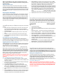
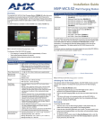
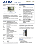
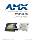
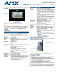
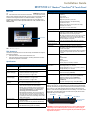
Installation Guide
MVP-5100 5.2" Modero® ViewPoint® IR Touch Panel
Overview
MVP-5100 Specifications (Cont.)
The MVP-5100 Modero® Viewpoint® IR Touch Panel (FG5966-08) is a one-way
IR-emitting ergonomic device. The MVP-5100 utilizes a 5.2" Color Active LCD to
display a 800 x 480 pixel image with 262,144 colors, and communicates with IR
receivers via its integral IR emitter. For detailed installation, configuration,
programming, file transfer, and operating instructions refer to the MVP-5100
Modero ViewPoint Touch Panel Operation/Reference Guide, available online at
www.amx.com.
Screen Properties:
• Screen resolution: 800 x 480 pixels (HV) @ 60 Hz frame
frequency
• Type: WVGA
• Aspect ratio: 16 x 9
•
•
•
•
•
•
IR Emitters
Brightness (luminance): 300 cd/m2
Channel transparency: 8-bit Alpha blending
Contrast ratio: 400:1
Display colors: 262,144 colors (18-bit color depth)
Dot/pixel pitch: 0.23 mm
Panel type: TFT Color Active-Matrix
External Components
Connector:
5-pin Mini-USB connector used for output to USB
programming, firmware update, and touch panel file
transfer between the PC and the target panel.
Note: When connecting the panel to PC using a CC-USB
(or compatible) cable, be sure to power the panel On
before attempting to connect the USB cable from the PC
to the mini-USB port on the panel.
DC Power Port:
2.5 mm port to power the panel away from a Charging
Station.
Touch Screen
Internal Components:
IR Emitters:
FIG. 1 MVP-5100 touch panel
FCC Statement
This device complies with FCC Part 15 and Industry Canada RSS 210 subject to
the following conditions:
1.
This device must not cause harmful interference and
2.
This device must accept all interference, including interference that interferes with the operation of this device.
Certifications:
•
•
•
•
•
•
FCC Part 15 Class B
CE
IEC/EN-60950
RoHS
Japan Approved
Lithium polymer microbattery: UN/IATA
Operating/Storage
Environment
•
•
•
•
Operating Temperature: 0° C (32° F) to 40° C (104° F)
Operating Humidity: 5% - 85% RH
Storage Temperature: -20° C (-4° F) to 60° C (140° F)
Storage Humidity: 5% - 85% RH
Included Accessories:
• Installation Guide (93-5966-01)
• PS3.0 Power Supply (FG423-30)
Other AMX Equipment:
•
•
•
•
Specifications
MVP-5100 Specifications (FG5966-08)
Dimensions:
4 3/4" x 7 9/16" x 13/16" (120.7 mm x 191.8 mm x 20.3
mm)
Weight:
• 1.25 lbs (0.57 kg)
Power Requirements
(Without Charging):
Panel with battery fully charged or with no battery:
• Constant current draw: 0.3 A @ 12 VDC
• Startup current draw: 0.4 A @ 12 VDC
Power Requirements
(While Charging):
Panel while charging battery:
• Constant current draw: 1.1 A @ 12 VDC
• Startup current draw: 1.3 A @ 12 VDC
Minimum Power Supply
Required:
PS3.0 Power Supply (FG423-30) - both 120 VAC and 240
VAC models are shipped with this power supply.
Power Modes:
• AWAKE: All necessary modules are powered up and
device remains online with the Netlinx Master.
• ASLEEP: Only the backlight will be turned off after the
user selectable time of inactivity has elapsed. Panel
resumes the Awake Mode in ~ 1 second upon a
momentary press of the touchscreen.
• PROCESSOR SHUTDOWN: Power to all peripherals
and components is turned off. The system remains in
this mode until it is rebooted. The panel is re-activated
by pressing the touchscreen and holding until the AMX
splash screen appears.
Battery Duration:
• 2.5 days of normal use, in a combination of Awake and
Shutdown Modes.
• Six hours of continuous use (continuous Awake state).
Memory:
• 128 MB Mobile DDRAM (upgrade not available)
• 256 MB NAND Flash (upgrade not available)
Transmit IR over 20 feet (6.10 m) from the panel.
• IR emitters on G4 panels share the device address
number of the panel.
• Transmits AMX fixed frequencies at 38KHz and 455KHz
and 8 user-programmable frequencies from 20KHz to
1.5MHz
MVP-TCS-52: Table Charging Station (FG5966-1X)
MVP-WCS-52: Wall Charging Station (FG5966-1X)
MVP-BP-5X: Battery Pack Kit (FG5966-27)
MVP-STYLUS-52-GB: Black Stylus, Pack of 3
(FG5966-21)
• CC-USB: USB Programming Cable (FG10-5965)
Table Charging Station Connector Locations
With the unit facing you, the mini-USB port (for programming and downloading
firmware) and the DC power jack are located on the lower left side of the device.
The connector for the Table Charging Station is located on the bottom of the
device.In cases where resetting the MVP-5100 is necessary or for access to the
Setup Pages, a recessed reset button is located on the top left, which can be
depressed using the included stylus.
Reset Button
Front
DC power jack
Mini-USB port
Charging Station
Connector
FIG. 2 MVP-5100 Connector Locations
WARNING: Transferring firmware KIT files over a direct USB connection
should only be done when the panel is connected to a power supply. If
battery power fails during a firmware upgrade, the panel flash file system
may become corrupted.
NOTE: The mini-USB port is only used for uploading firmware to the
device. It cannot be used for headphones, speakers, receiving power, or
any other function.
Infrared Communication
The MVP-5100 may be used as an infrared remote device for other AMX
controllers or third-party devices. The device can transmit IR over 20 feet
(6.10 m) from the panel at AMX fixed IR frequencies of 38KHz and 455KHz, as
well as up to eight user-programmed frequencies between 20KHz and 1.5MHz.
IR receivers and transmitters on G4 panels share the device address number
of the panel.
Accessing the Setup Pages
The MVP-5100 features on-board Setup pages. Use the options in the Setup
pages to access panel information and make various configuration changes.
To access the Setup pages, use the included stylus tip to press the recessed
button on the left top side of the device and hold for three seconds. A popup
screen opens that reads “Release button now to enter the Setup Pages.
Continue holding to enter Calibration.” Releasing the recessed button at that
time opens the main Setup page.
For more information, refer to the Setup Pages section of the MVP-5100/50
Modero ViewPoint Touch Panel Operation/Reference Guide, available at
www.amx.com.
Accessing the Calibration Page
The Calibration page allows you to calibrate the touch panel for accurate button
selection.
1.
2.
3.
4.
Press and hold the recessed button on the left side of the device until a
screen appears that reads “Release button now to enter Calibration
Page, Continue holding to shut down panel”. Release the button to open
the Calibration page.
Press the crosshairs to calibrate the panel and return to the previous
page.
This page may also be accessed through the Protected Setup page.
Always calibrate the panel before its initial use, and after downloading
new firmware.
Accessing the Protected Setup Page
The Protected Setup page provides secured access to advanced panel
configuration options, including communication and security settings. Enter the
factory default password (1988) into the password keypad to access this page.
7.
ONLY AFTER the unit displays the first panel page should you THEN
insert the mini-USB connector into the Mini-USB Port on the panel. It may
take a minute for the panel to detect the new connection and send a
signal to the PC, indicated by a green System Connection icon.
• If a few minutes have gone by and the System Connection icon still does
not turn green, set up the Virtual Master (for more information, refer to the
Step 2: Prepare Studio for communication via the USB port section in the
MVP-5100/50 Modero Viewpoint Touch Panel Operation/Reference
Guide, available at www.amx.com) and refresh the System from the
Online Tree. This action sends out a request to the panel to respond and
completes the communication, turning the System Connection icon green.
8.
Repeat steps 2 and 3 to return to the System Settings page.
For more information, refer to the Upgrading Firmware section of the MVP5100/50 Modero Viewpoint Touch Panel Operation/Reference Guide, available
at www.amx.com.
Uploading IR Codes to the MVP-5100
Since the MVP-5100 communicates with other devices through IR instead of
through WiFi, making sure that the device has the latest IR codes is vital. To
ensure that the IR codes installed on the device are the most suitable, use
NetLinx Studio to upload newly available codes via the AMX IRN database.
All IR code files used by NetLinx Studio are in the .IRN format. These may be
created via IREdit (available from www.amx.com), supplied from a personal
IRN database, or from the AMX IRN database. To access the available IRN
files:
1.
2.
3.
•
•
•
4.
5.
6.
7.
Launch NetLinx Studio.
Open the NetLinx Workspace.
Right-click on the IR folder and select the method to add the necessary IR
files.
Add Existing IR File... chooses from a previously downloaded IR file
Add From AMX IR Database... chooses from AMX’s IR file database
Add From User IR Database... chooses from a personal IR file database
When the IR file appears in the Workspace Tree, right-click on the file and
select Device Mapping... to open the Device Mapping window.
Click the Map button to open the Enter DPS window and enter the device
number, port number, and system number for the touch panel.
Click OK to close the window. The IR file will now appear in the
Workspace pane.
From the main menu, select Tools > Firmware Transfers > Send To
NetLinx Device... to open the Send to NetLinx Device window.
Select the file to be transferred and click Close when finished.
Upgrading Firmware Via the USB Port
8.
The MVP-5100 uses a 5-pin CC-USB (Type A) to Mini-B 5-Wire programming
cable (FG10-5965) for programming, firmware updates, and touch panel file
transfer between the PC and the target device. If a programming cable is not
available, it may be purchased from www.amx.com. The Mini-USB port for the
connector is located on the left side of the device as viewed from the front.
For more information, refer to the Upgrading IR Codes to the MVP-5100
section of the MVP-5100/50 Modero Viewpoint Touch Panel Operation/
Reference Guide, available at www.amx.com.
Before starting, verify that the device is powered and the Type-A end of the
USB connector is inserted and secure in the PC’s USB port. The panel must
be powered On before connecting the mini-USB connector to the panel.
To guarantee that the upgrade is not interrupted by power loss, connecting the
device to a power source, such as inserting it in a Table Charging Station,
before beginning the upgrade is highly recommended.
Always use a clean cotton cloth and a spray bottle containing water or a
vinegar-based cleaner to clean the MVP-5100, as alcohol-based cleaners can
damage the device. Do not directly spray the device: instead, spray the cloth
to clean the touch screen overlay. Do NOT use an abrasive of any type to clean
the MVP-5100, as this may permanently damage or remove the device’s finish.
WARNING: Establishing a USB connection between the PC and the panel,
prior to installing the USB Driver, will cause a failure in the USB driver
installation.
The battery powering the MVP-5100 is designed for upwards of 300 deep
discharge rechargings. Regular shallow rechargings will extensively increase
expected battery life, and the device should be stored in either a Table
Charging Station or Wall Charging Station when not in use to keep it at an
optimum charge. The battery has reached its effective end of life after it can no
longer hold more than a 70 percent charge.
Step 1: Configure the panel for a USB Connection Type
1.
2.
3.
4.
5.
6.
After completing the installation of the USB driver, confirm the proper
installation of the large Type-A USB connector to the PC's USB port, and
restart your computer.
After the panel powers up, hold the reset button to display the Setup Page
and open the Protected Setup page.
Press System Settings to open the System Settings page.
Toggle the blue Type field in the Master Connection section until the
choice cycles to USB. NOTE: ALL fields are then grayed out and readonly. However, they still display any previous network information.
Press the Back button on the touch panel to return to the Protected Setup
page.
Press the Reboot button to both save any changes and restart the panel.
Remember that the panel’s connection type must be set to USB prior to
rebooting the panel and prior to inserting the USB connector.
Cleaning the Touch Overlay and Case
Battery Life and Replacement
Proper Battery Maintenance
NOTE: To insure maximum performance and reliability of your AMX
Wireless Touch Panel, please insure that a full charge is performed every
3 months if not used regularly. If a battery is left uncharged beyond this
time frame, it may result in premature battery lifespan degradation and
will require replacement.
For full warranty information, refer to the AMX Operation/Reference Manual(s) associated with your Product(s).
2/10
©2010 AMX. All rights reserved. AMX and the AMX logo are registered trademarks of AMX.
AMX reserves the right to alter specifications without notice at any time.
3000 RESEARCH DRIVE, RICHARDSON, TX 75082 • 800.222.0193 • fax 469.624.7153 • technical support 800.932.6993 • www.amx.com
93-5966-08
REV: F