1
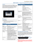
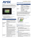
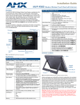
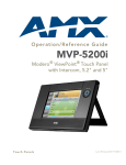
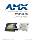
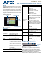
Installation Guide
MVP-5200i
Modero® Viewpoint® Widescreen Touch Panel
Overview
MVP-5200i Specifications (Cont.)
The MVP-5200i Modero® Viewpoint® Widescreen Touch Panel is AMX’s smallest and
most powerful wireless handheld panel, available in black (FG5966-01) and white
(FG5966-02). The MVP-5200i is a wireless-only ergonomic device capable of Voice
Over Internet Protocol (VoIP) communication, with all control established through a
NetLinx Master. Besides offering the same functionality as the rest of AMX’s line of G4
touch panels, the MVP-5200i touch panel offers full duplex VoIP communication, quick
wakeup and connection time, and an extended battery life for longer operation
between charges. The MVP-5200i device utilizes a 5.2" Color Active LCD to display a
800 x 480 pixel image with 262,144 colors.
The MVP-5200i comes with an integrated rear "kickstand", allowing it to be used and
displayed away from a docking station if necessary. It also comes with a pre-installed
802.11g WPA/WPA2 SDIO wireless card.
For detailed installation, configuration, programming, file transfer, and operating
instructions refer to the MVP-5200i Modero ViewPoint Touch Panel User Manual,
available online at www.amx.com.
Screen Properties:
•
•
•
•
•
•
Navigation
Wheel
Touch Screen
Connector:
IR Emitters:
•
•
•
•
•
•
FCC Part 15 Class B
CE
IEC/EN-60950
RoHS
Japan Approved
Lithium polymer microbattery: UN/IATA
Operating/Storage
Environment
•
•
•
•
Operating Temperature: 0° C (32° F) to 40° C (104° F)
Operating Humidity: 20% - 85% RH
Storage Temperature: -20° C (-4° F) to 60° C (140° F)
Storage Humidity: 5% - 85% RH
Included Accessories:
• Installation Guide (93-5966-01)
• PS3.0 Power Supply (FG423-30)
• MVP-STYLUS-52 (pre-installed onto the right side of the
unit) (FG5966-06XX)
Other AMX Equipment:
•
•
•
•
Specifications
4 3/4" x 7 9/16" x 13/16" (120.7 mm x 191.8 mm x 20.3
mm)
Weight:
• Panel: 1.4 lbs (0.64 kg)
Power Requirements
(Without Charging):
Panel with battery fully charged or with no battery:
• Constant current draw: 0.3 A @ 12 VDC
• Startup current draw: 0.4 A @ 12 VDC
Power Requirements
(While Charging):
Panel while charging battery:
• Constant current draw: 1.1 A @ 12 VDC
• Startup current draw: 1.3 A @ 12 VDC
Minimum Power Supply
Required:
PS3.0 Power Supply (FG423-30) - both 120 VAC and 240
VAC models are shipped with this power supply.
Power Modes:
• AWAKE: All necessary modules are powered up and
device remains online with the Netlinx Master.
• ASLEEP: Only the backlight will be turned off after the
user selectable time of inactivity has elapsed. Panel
resumes the ON mode in ~ 1 second.
• STANDBY: Power to all components other than the
touch screen is turned off after the user selectable time
of inactivity has elapsed. Device will turn back on by
touching the screen.
• SHUTDOWN: Power to all peripherals and components
is turned off. The system remains in this mode until it is
rebooted.
Battery Duration:
• Four days of normal use, in a combination of Awake,
Standby, and Shutdown.
• Eight hours of continuous use (continuous On state).
Memory:
• 128 MB Mobile DDRAM (upgrade not available)
• 256 MB NAND Flash (upgrade not available)
Transmit IR over 20 feet (6.10 m) from the panel.
• IR emitters on G4 panels share the device address
number of the panel.
• Transmits AMX fixed frequencies at 38KHz and 455KHz
and user programmable frequencies from 20KHz to
1.5MHz
Certifications:
Speaker Grille
Dimensions:
5-pin Mini-USB connector used for output to USB
headphones, programming, firmware update, and touch
panel file transfer between the PC and the target panel.
Note: When connecting the panel to PC using a CC-USB
(or compatible) cable, be sure to power the panel On
before attempting to connect the USB cable from the PC
to the mini-USB port on the panel.
Internal Components:
FIG. 1 MVP-5200i-GB touch panel
MVP-5200i Specifications
Brightness (luminance): 300 cd/m2
Channel transparency: 8-bit Alpha blending
Contrast ratio: 20:1
Display colors: 262,144 colors (18-bit color depth)
Dot/pixel pitch: 0.23 mm
Panel type: TFT Color Active-Matrix
External Components
Navigation Wheel LED
Microphone
• Screen resolution: 800 x 480 pixels (HV) @ 60 Hz frame
frequency
• Type: WVGA
• Aspect ratio: 16 x 9
MVP-TCS-52: Table Charging Station (FG5966-1X)
MVP-WCS-52: Wall Charging Station (FG5966-1X)
MVP-BP-5X: Battery Pack Kit (FG5966-27)
MVP-STYLUS-52: Replacement Stylus, Pack of 3
(FG5966-2X)
• CC-USB: USB Programming Cable (FG10-5965)
• MVP-HPUSB 1/8” Adapter (FG5966-23)
Table Charging Station Connector Locations
Front
DC power jack
Mini-USB port
Charging Station
Connector
FIG. 2 MVP-5200i Connector Locations
With the unit facing you, the mini-USB port (for programming and downloading
firmware, as well as connecting USB headphones using the AMX-provided adaptor
cable) and the DC power jack are located on the lower left side of the device. The
connector for the Table Charging Station is located on the bottom of the device.
The MVP-5200i is the first G4 device to support a new Ethernet over USB driver for
panel downloads and firmware updates. This means that the device can connect to the
Internet through its mini-USB port instead of through a standard Ethernet port.
In addition to its speaker, the MVP-5200i also utilizes its mini-USB port as a connector
for standard headphones or headsets. These headphones must use a mini-USB plug
or adapter, such as the MVP-HP USB 1/8” Adapter, in order to utilize this feature.
While standard input/output headsets may be used in lieu of headphones, the
headset may only be used for output. While you may receive sound from the
headset, its microphone will not function. Always use the MVP-5200i’s microphone
for receiving sound.
WARNING: Although firmware upgrades can be conducted over a wireless
Ethernet connection, transferring firmware KIT files over a direct USB
connection is recommended, and only when the panel is connected to a power
supply. If battery power or wireless connection fails during a firmware
upgrade, the panel flash file system may become corrupted.
Navigation Wheel
The MVP-5200i device uses a button wheel for commands made other than through
the touchscreen. This wheel, known as a navigation wheel, is located in the upper
right corner of the device. Used with the touchscreen, the navigation wheel allows
scrolling and adjusting by turning the wheel with a thumb or finger and then pressing
down on one of the wheel’s compass points for up, down, left, and right. The wheel is
sensitive enough to adjust levels with one-third of a rotation. The center of the
navigation wheel is also a button: for example, pressing down directly upon the
wheel center could be used for the equivalent of an "Enter" keystroke.
If the MVP-5200i needs to be shut down or reset for any reason, press and hold
down the wheel center button until the popup stating “panel shutting down” appears
or the screen goes dark. When in its Standby Power Mode, the MVP-5200i may only
be returned to its Awake state by touching the screen.
The navigation wheel also lights up depending upon the Power Mode it is in at the
time. The navigation wheel LED lights when the touch screen is on and turns off
when the touchscreen is off, with the exception of when the device is charging. The
flashing during recharging may be disabled via the device’s on-board Setup page.
For more information, please see the MVP-5200i Modero ViewPoint Touch Panel
User Manual, available at www.amx.com.
Turning on the MVP-5200i
The MVP-5200i uses one of two methods to turn it on. These use either the
navigation wheel or the touchscreen. To learn which method works for your panel:
1.
Press any of the navigation wheel’s compass points and hold until the AMX
splash screen appears on the touchscreen.
2.
If the navigation wheel does not respond, press the touchscreen and hold until
the AMX splash screen appears on the touchscreen.
Accessing the Setup Pages
The MVP-5200i features on-board Setup pages. Use the options in the Setup pages
to access panel information and make various configuration changes.
To access the Setup pages, press the center button on the navigation wheel and
hold for three seconds. A popup screen opens that reads “Release button now to
enter the Setup Pages. Continue holding to enter Calibration.” Releasing the center
button at that time opens the main Setup page.
For more information, refer to the Setup Pages section of the MVP-5200i Modero
ViewPoint Touch Panel User Manual, available at www.amx.com.
Accessing the Calibration Page
The Calibration page allows you to calibrate the touch panel for accurate button
selection.
1.
Press and hold the center button on the navigation wheel until theCalibration
page opens. (This page may also be accessed through the Protected Setup
page.)
2.
Press the crosshairs to calibrate the panel and return to the previous page.
3.
Always calibrate the panel before its initial use, and after downloading new
firmware.
Accessing the Protected Setup Page
The Protected Setup page provides secured access to advanced panel configuration
options, including communication and security settings. Enter the factory default
password (1988) into the password keypad to access this page.
Setting the Panel’s Device Number
In the Protected Setup page:
1.
Press the Device Number field to open the Device Number keypad.
2.
Enter a unique Device Number assignment for the panel, and press Done to
return to the Protected Setup page. The Device Number range is 1 - 32000,
and the default is 10001.
Configuring the Panel’s Wireless IP Settings
The first step to successfully setting up the internal wireless card is to configure the
IP Settings section on the Wireless Settings page. This section configures the
communication parameters from the MVP panel to the web.
3.
4.
Press the optional Host Name field to open a Keyboard and enter the Host
Name information.
Press Done after you are finished assigning the alpha-numeric string of the
host name.
Configuring the Card’s Wireless Settings
The second step of a successful setup of the wireless card is to configure the
Wireless Security section of the Wireless Settings page. This section configures both
the communication and security parameters from the internal wireless card to the
WAP.
Configuring the Wireless Card for Secured Access to the WAP
In the Protected Setup page:
1.
Select Wireless Settings.
2.
Press the Site Survey button to access the Wireless Site Survey page.
3.
Select a WEP secured WAP from within the Wireless Site Survey page, as
displayed in the Security field, and press the Connect button to display the
Static WEP Settings popup.
4.
Enter the key length and values for matching the WAP and press Save.
5.
The Access Point MAC Address field will now be filled.
6.
Press Back to return to the Protected Setup page.
NOTE: Consult the MVP-5200i Modero ViewPoint Touch Panel User Manual for
manually entering the SSID information.
Choose a Master Connection Mode
The panel requires the establishment of the type of connection to be made between
it and the master.
In the Protected Setup page:
1.
Select System Settings.
2.
Select Type to toggle between the Master Connection Types USB and
Ethernet.
A USB connection is a direct connection from the panel’s mini-USB port to a
corresponding USB port on the PC (acting as a Virtual Master).
A Wireless Ethernet connection involves indirect communication from the
panel to a Master via a wireless connection to the network.
Upgrading Firmware
For the purpose of panel downloads, the MVP-5200i’s download procedure is not
compatible with other AMX panel devices. This is due to the unique configuration of
the device.
The first major change from other AMX devices is that the MVP-5200i uses dynamic
Setup Pages for its displays. Instead of requiring a separate Setup Page project built
within TPDesign 4, the MVP-5200i uses only a single set of Setup Pages for all of its
supported resolutions.
To enable a single Setup Page project to support all resolutions, it will be necessary
to include images for the largest supported resolution with the Setup Page project
and to scale the images to fit for lower resolutions. This modification would apply to
state-level bitmaps and chameleon images, whereas previously, image scaling has
only applied to dynamic images.
For more information, refer to the Upgrading Firmware section of the MVP-5200i
Modero Viewpoint Touch Panel User Manual, available at www.amx.com.
Cleaning the Touch Overlay, Case, and Navigation Wheel
Always use a clean cotton cloth and a spray bottle containing water or a vinegarbased cleaner when cleaning the MVP-5200i, as alcohol-based cleaners can
damage the device. Do not directly spray the device: instead, spray the cloth to
clean the touch screen overlay and navigation wheel. Do NOT use an abrasive of
any type to clean the MVP-5200i, as this may permanently damage or remove the
device’s finish.
Battery Life and Replacement
The battery powering the MVP-5200i is designed for upwards of 300 deep discharge
rechargings. Regular shallow rechargings will extensively increase expected battery
life, and the device should be stored in either a Table Charging Station or Wall
Charging Station when not in use to keep it at an optimum charge. The battery has
reached its effective end of life after it can no longer hold more than a 70 percent
charge.
Proper Battery Maintenance
NOTE: To insure maximum performance and reliability of your AMX Wireless
Touch Panel, please insure that a full charge is performed every 3 months if
not used regularly. If a battery is left uncharged beyond this time frame, it may
result in premature battery lifespan degradation and will require replacement.
Wireless Communication Using a DHCP Address
In the Protected Setup page:
1.
Select Wireless Settings. Wireless communication is set within the IP Settings
section of this page.
2.
Toggle the DHCP/Static field (from the IP Settings section) until the choice
cycles to DHCP. This action causes all fields in the IP Settings section other
than Host Name to be greyed-out. Once the panel is rebooted, these values
are obtained by the unit and displayed in the DNS fields after power-up.
NOTE: DHCP will register the unique MAC Address (factory assigned) on
the panel and once the communication setup process is complete,
assign IP Address, Subnet Mask, and Gateway values from the DHCP
Server.
For full warranty information, refer to the AMX Instruction Manual(s) associated with your Product(s).
11/09
©2009 AMX. All rights reserved. AMX and the AMX logo are registered trademarks of AMX.
AMX reserves the right to alter specifications without notice at any time.
3000 RESEARCH DRIVE, RICHARDSON, TX 75082 • 800.222.0193 • fax 469.624.7153 • technical support 800.932.6993 • www.amx.com
93-5966-01
REV: H