1
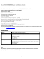
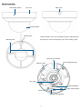
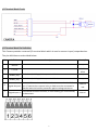
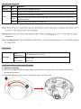
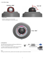
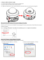
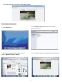
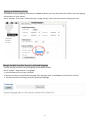
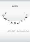
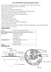
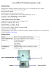
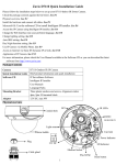
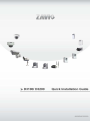
1
86085H9000000
Zavio D3100/D3200 Quick Installation Guide
Please follow the installation steps below to set up D3100 / D3200 Fixed Dome IP Camera.
Check the package contents against the list below. See P.1
Physical overview. See P.2
I/O Terminal Block Circuit. See P.3
I/O Terminal Block Pin Definition. See P.3
LED Indicator Definition. See P.4
Power mode. See P.4
Install the hardware and connect all cables. See P.4
Microsoft OS: Use the software CD to install Intelligent IP Installer. See P.7
Access the IP Camera using Intelligent IP Installer. See P.7
Mac OS using Safari Browser. See P.9
Change light environment setting. See P.10
Change the Web Interface into your preferred language. See P.10
Application of IP Camera. See P.11
For more information, please check the User Manual available in the Software CD or you can download the latest
software from http://www.zavio.com
Package Contents
Camera
D3100 / D3200 Fixed Dome IP Camera
Quick Installation Guide
Brief product information and quick installation
Software CD
IP Surveillance Software
Intelligent IP Installer
User Manuals
Language Packs
Accessory
6 pin terminal cable for DI/DO and audio
Screw pack for wall and ceiling mounting ( 2 screws, 2 plastic wall anchors )
Focus Adjustment
Drill Template
Note:
CAT5 cables are supplied by user. RJ45 Ethernet network connection (using CAT5 standard UTP or better
quality cable) for Power over Ethernet (PoE 802.3af)
1
Physical overview
Built-in Microphone
Slide cover
Top cover
Dome bubble
Routing hole
Leave the slide cover if you would like to plug in cables through
the side of top cover and through a hole on the ceiling or wall.
Mounting hole
External I/O connector
Ethernet / PoE
Focus Adjustment Ring
180° mark
MicroSD/SDHC
Power LED Indicator
Reset
Network LED Indicator
2
I/O Terminal Block Circuit
I/O Terminal Block Pin Definition
This Camera provides a external I/O terminal block which is used to connect input/ output devices.
The pin definitions are described below.
PIN
Definition
1
Ground
-
2
+ 5V DC
5V DC
0.5W
3
AUDIO_In(+)
Unbalanced, 1.4Vp-p, 1Vrms, terminal block
-
4
AUDIO_In(+)
Unbalanced, 1.4Vp-p, 1Vrms, terminal block
-
Uses an NPN transistor with the emitter connected to the GND
Digital Output 1 pin. If used with an external relay, a diode must be connected in
parallel with the load for protection against voltage transients.
100 mA
24V
5
7
Digital Input 1
Description
Connected to GND to activate, or leave floating (or unconnected)
to deactivate.
3
Max. V/A
30V DC
LED Indicator Definition
LED
Color
Indication
Network
Blue
Flash blue while Network activity.
Red
Steady red for booting up process; Steady red 30 Seconds when WPS configure failed.
Blue
Steady blue for booting up completion
Purple
Flash purple during firmware upgrading; when reset button pressed for at least 5 sec.
to factory default
Unlit
When you press reset button; or Power off
Power
Power Mode
PoE Mode
Power
Requirement
PoE (IEEE802.3af) with Class 3
Power
Consumption
D3100: 2.5W
D3200: 5W
Install the hardware and connect all cables
a. Hardware Installing
1) Before connecting the Ethernet cable, please use one hand to hold top cover and another hand to press
the bottom of camera.
2) Then shift top cover to left (counter-clockwise) to open the dome cover.
4
b. Wall mounting and Ceiling mounting
1) Attached the drill template to the wall. Drill three holes into the wall, which two for screws and one for cable
(if you want to route cables through conduit hole). Then hammer the supplied plastic anchors into the screw
holes and secure the plate with supplied screws.
2) Align the three holes on the base of camera with the two plastic anchors on the wall or ceiling, insert the
supplied screws to the corresponding hole and screw them.
3) Adjust the angle of camera to aim the shooting area.
Note:
When using this device, please use an Ethernet cable without the strain relief boot.
5
c. Lens focus range
Rotate 360°
Tilt 79°
Rotate Notice:
DO NOT rotate the lens over 2 rounds.
Doing so will damage the camera lens module.
Pan 344°
d. Completion
The camera has only Power over Ethernet (PoE) built-in.
(there is no DC connector inside.)
1. Using a standard RJ-45 network cable, connect the IP
Camera to a PoE-enabled Hub / Switch / Router.
Note:
If using a non-PoE switch, please use a PoE power injector to connect the camera.
6
e. Connect cables and power supply
1) Clean the dome bubble to remove the dust and finger print.
2) Align the slide cover down to the U-shape position.
3) Tighten the dome cover to the clockwise direction and make slide cover reaching the routing hole.
Microsoft OS:Use the software CD to install Intelligent IP Installer
Power on your PC and insert the CD-ROM. The setup page will show up automatically. Please follow these steps to
install the firmware.
Select “Intelligent IP Installer” and follow the installation process to complete the installation.
Access the IP Camera using Intelligent IP Installer
1. Please check two settings before using Intelligent IP Installer .
b. Browser’s Internet Properties → Privacy
→ Uncheck Pop-up Blocker
a. Browser’s Internet Properties → Security
→ Default Level
7
2. Click the Intelligent IP Installer Icon on your desktop. The main page will show up listing all active
camera and video server devices. Select the relevant IP camera from the list and click Link to IE.
2
3. Enter your Username and Password
to login to the IP Camera.
(Default is admin / admin)
4. When accessing the IP Camera for the first time, a yellow information bar appears below the address bar:
This website wants to install the following add-on: ‘AxvideoView.cab from ‘Zavio Inc’.
5. Click the information bar, and select Install ActiveX control.
6. Click Install.
8
7. Live video displays in the centre of your web browser.
Mac OS using Safari Browser
1. Select Safari icon
2. Click Bonjour function and select the camera
you wish to access.
3. Enter name and password to login to the IP
4. The monitor image will be displayed in your browser.
camera. (Default is admin / admin)
9
Lighting environment setting
The default setting of lighting environment is Auto. However, you may also select 50 or 60 Hz upon the lighting
environment of your country.
Go to “Setting > Live View > Camera Setting > Image Setting”, select the environment setting you wish.
Change the Web Interface into your preferred language
Use the settings screen to set the language of the Web Interface.
Go to “System > Maintenance > Language”.
1. Insert Software CD into your CD-ROM.
2. Browse and select the preferred language from language pack in the Software CD and then click OK.
3. The web interface will change into your preferred language.
10
Application of IP Camera
11
12