1
®
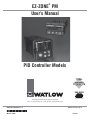
EZ-ZONE PM
User’s Manual
PID Controller Models
TOTAL
CUST
CUS
TOMER
SATISF
TISFA
ACTI
CTIO
ON
3 Year Warranty
ISO 9001
Registered Company
Winona, Minnesota USA
1241 Bundy Boulevard., Winona, Minnesota USA 55987
Phone: +1 (507) 454-5300, Fax: +1 (507) 452-4507 http://www.watlow.com
0600-0058-0000 Rev. C
March 2008
Made in the U.S.A.
$15.00
Safety Information
• Complete model number
We use note, caution and warning symbols throughout this book to draw your attention to important
operational and safety information.
• All configuration information
A “NOTE” marks a short message to alert you to
an important detail.
A “CAUTION” safety alert appears with information that is important for protecting your equipment and performance. Be especially careful to
read and follow all cautions that apply to your
application.
A “WARNING” safety alert appears with information that is important for protecting you, others and equipment from damage. Pay very close
attention to all warnings that apply to your
application.
The safety alert symbol, ç (an exclamation point
in a triangle) precedes a general CAUTION or
WARNING statement.
The electrical hazard symbol, Ó (a lightning bolt
in a triangle) precedes an electric shock hazard
CAUTION or WARNING safety statement.
ç
Ó
CAUTION or WARNING
Electrical Shock Hazard
CAUTION or WARNING
Warranty
The EZ-ZONE® PM is manufactured by ISO
9001-registered processes and is backed by a threeyear warranty to the first purchaser for use, providing that the units have not been misapplied. Since
Watlow has no control over their use, and sometimes
misuse, we cannot guarantee against failure. Watlow’s obligations hereunder, at Watlow’s option, are
limited to replacement, repair or refund of purchase
price, and parts which upon examination prove to be
defective within the warranty period specified. This
warranty does not apply to damage resulting from
transportation, alteration, misuse or abuse. The purchaser must use Watlow parts to maintain all listed
ratings.
Technical Assistance
If you encounter a problem with your Watlow controller, review your configuration information to verify
that your selections are consistent with your application: inputs, outputs, alarms, limits, etc. If the problem persists, you can get technical assistance from
your local Watlow representative (see back cover), by
e-mailing your questions to wintechsupport@watlow.
com or by dialing +1 (507) 494-5656 between 7 a.m.
and 5 p.m., Central Standard Time (CST). Ask for for
an Applications Engineer. Please have the following
information available when calling:
• User’s Manual
• Factory Page
Return Material Authorization (RMA)
1. Call Watlow Customer Service, (507) 454-5300,
for a Return Material Authorization (RMA) number before returning any item for repair. If you
do not know why the product failed, contact an
Application Engineer or Product Manager. All
RMA’s require:
• Ship-to address
• Bill-to address
• Contact name
• Phone number
• Method of return shipment
• Your P.O. number
• Detailed description of the problem
• Any special instructions
• Name and phone number of person returning
the product.
2. Prior approval and an RMA number from the
Customer Service Department is required when
returning any product for credit, repair or evaluation. Make sure the RMA number is on the outside of the carton and on all paperwork returned.
Ship on a Freight Prepaid basis.
3. After we receive your return, we will examine it
and try to verify the reason for returning it.
4. In cases of manufacturing defect, we will enter a
repair order, replacement order or issue credit for
material returned. In cases of customer mis-use,
we will provide repair costs and request a purchase order to proceed with the repair work.
5.
To return products that are not defective, goods
must be be in new condition, in the original boxes
and they must be returned within 120 days of
receipt. A 20 percent restocking charge is applied
for all returned stock controls and accessories.
6. If the unit is unrepairable, you will receive a
letter of explanation. and be given the option to
have the unit returned to you at your expense or
to have us scrap the unit.
7. Watlow reserves the right to charge for no trouble found (NTF) returns.
The EZ-ZONE® PM PID Controller User’s Manual
is copyrighted by Watlow Winona, Inc., © July 2007
with all rights reserved.
EZ-ZONE® PM is covered by U.S. Patent No.
6,005,577 and Patents Pending
TC
Table of Contents
Chapter 1: Overview . . . . . . . . . . . . . . . . . . . . . . . . . . . . . . . . . . . . .2
Standard Features and Benefits . . . . . . . . . . . . . . . . . . . . . . . . . . . . . . . 2
Chapter 2: Install and Wire . . . . . . . . . . . . . . . . . . . . . . . . . . . . . . . . .5
Chapter 3: Keys and Displays . . . . . . . . . . . . . . . . . . . . . . . . . . . . . . 17
Chapter 4: Home Page . . . . . . . . . . . . . . . . . . . . . . . . . . . . . . . . . . . 20
Attention Codes . . . . . . . . . . . . . . . . . . . . . . . . . . . . . . . . . . . . . . . . . . 20
Chapter 5: Operations Page . . . . . . . . . . . . . . . . . . . . . . . . . . . . . . . 22
Chapter 6: Setup Page . . . . . . . . . . . . . . . . . . . . . . . . . . . . . . . . . . . 27
Chapter 7: Profiling Page . . . . . . . . . . . . . . . . . . . . . . . . . . . . . . . . . 37
Chapter 8: Factory Page . . . . . . . . . . . . . . . . . . . . . . . . . . . . . . . . . . 41
Chapter 9: Features . . . . . . . . . . . . . . . . . . . . . . . . . . . . . . . . . . . . . 45
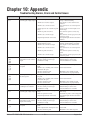
Chapter 10: Appendix . . . . . . . . . . . . . . . . . . . . . . . . . . . . . . . . . . . 58
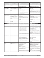
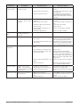
Troubleshooting Alarms, Errors and Control Issues . . . . . . . . . . . . . . 58
Specifications . . . . . . . . . . . . . . . . . . . . . . . . . . . . . . . . . . . . . . . . . . . . 61
Ordering Information for PID Controller Models . . . . . . . . . . . . . . . . . 63
Index . . . . . . . . . . . . . . . . . . . . . . . . . . . . . . . . . . . . . . . . . . . . . . . . . . . 64
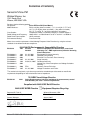
Declaration of Conformity . . . . . . . . . . . . . . . . . . . . . . . . . . . . . . . . . . . 68
Watlow EZ-ZONE ® PM PID Controller
•
1 •
Table of Contents
1
Chapter 1: Overview
The EZ-ZONE ® PM takes the pain out of solving
your thermal loop requirements.
Watlow’s EZ-ZONE ® PM controllers offer options
to reduce system complexity and the cost of controlloop ownership. You can order the EZ-ZONE ® PM as
a PID controller or an over-under limit controller, or
you can combine both functions in the PM Integrated Limit Controller. You now have the option to integrate a high-amperage power controller output, an
over-under limit controller and a high-performance
PID controller all in space-saving, panel-mount
packages. You can also select from a number of serial communications options to help you manage system performance.
It just got a whole lot easier to solve the thermal requirements of your system. Because the EZZONE ® PM controllers are highly scalable, you only
pay for what you need. So if you are looking for a
PID controller, an over-under limit controller or an
integrated controller, the EZ-ZONE ® PM is the answer.
Agency approvals: UL Listed, CSA, CE, RoHS,
W.E.E.E. FM
• Assures prompt product acceptance
Standard Features and Benefits
• Simplified installation
Advanced PID Control Algorithm
• TRU-TUNE+ ® Adaptive tune provides tighter control for demanding applications.
EZ-Key
• Programmable EZ-Key enables simple one-touch
operation of repetitive user activities
• Auto Tune for fast, efficient start ups
Programmable Menu System
• Reduces set up time and increases operator efficiency
• Reduces end product documentation costs
• Semi F47-0200
P3T Armor Sealing System
• NEMA 4X and IP66 offers water and dust resistance, can be cleaned and washed down
• Backed up by UL 50 independent certification to
NEMA 4X specification
Three-year warranty
• Demonstrates Watlow’s reliability and product
support
Touch-safe Package
• IP2X increased safety for installers and operators
Removable cage clamp wiring connectors
• Reliable wiring, reduced service calls
High-amperage Power Control Output
• Drives 15 amp resistive loads directly
• Saves panel space and simplifies wiring
Full-featured Alarms
• Improves operator recognition of system faults
• Reduces the cost of ownership
• Control of auxiliary devices
EZ-ZONE ® configuration communications and
software
• Saves time and improves the reliability of controller set up
Heat-Cool Operation
• Provides application flexibility with accurate temperature and process control
• Reduces component count
Profile Capability
• Preprogrammed process control
Parameter Save & Restore Memory
• Reduces service calls and down time
Watlow EZ-ZONE ® PM PID Controller
• Ramp and soak programming with four files and
40 total steps
•
2
•
Chapter 1 Over view
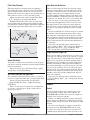
A Conceptual View of the PM
The flexibility of the PM’s software and hardware allows a large range of configurations. Acquiring a better understanding of the controller’s overall functionality and capabilities while at the same time planning out how the controller can be used will deliver
maximum effectiveness in your application.
It is useful to think of the controller in three
parts: inputs; procedures; and outputs. Information
flows from an input to a procedure to an output when
the controller is properly configured. A single PM
controller can carry out several procedures at the
same time, for instance closed-loop control, monitoring for several different alarm situations and operating switched devices, such as lights and motors.
Each process needs to be thought out carefully and
the controller’s inputs, procedures and outputs set up
properly.
Inputs
The inputs provide the information that any given
programmed procedure can act upon. In a simple
form, this information may come from an operator
pushing a button or as part of a more complex procedure it may represent a remote set point being received from another controller.
Each analog input typically uses a thermocouple
or RTD to read the temperature of something. It can
also read volts, current or resistance, allowing it to
use various devices to read humidity, air pressure,
operator inputs and others values. The settings in
the Analog Input Menu (Setup Page) for each analog
input must be configured to match the device connected to that input.
Each digital input reads whether a device is active
or inactive. A PM with digital input-output hardware
includes two sets of terminals each of which can be
used as either an input or an output. Each pair of
terminals must be configured to function as either
an input or output with the Direction parameter in
the Digital Input/Output Menu (Setup Page).
The Function or EZ Key on the front panel of the
PM also operates as a digital input by toggling the
function assigned to it in the Digital Input Function
parameter in the Function Key Menu (Setup Page).
Keep in mind that a function is a user-programmed
internal process that does not execute any action outside of the controller. To have any effect outside of the
controller, an output must be configured to respond
to a function.
Outputs
Outputs can perform various functions or actions in
response to information provided by a function, such
as operating a heater; turning a light on or off; unlocking a door; or turning on a buzzer.
Assign an output to a Function in the Output
Menu or Digital Input/Output Menu. Then select
which instance of that function will drive the selected output. For example, you might assign an output
to respond to alarm 4 (instance 4) or to retransmit
the value of analog input 2 (instance 2).
You can assign more than one output to respond
to a single instance of a function. For example, alarm
2 could be used to trigger a light connected to output
1 and a siren connected to digital output 5.
Input Events and Output Events
Input events are internal states that are set by the
digital inputs. Digital input 5 provides the state of
input event 1, and digital input 6 provides the state
of input event 2. Wait for Event steps in profiles
are triggered by these events. The setting of Digital
Input Function (Setup Page, Digital Input/Output
Menu) does not change the relationship between the
input and the event, so take care not to configure the
function in a way that would conflict with a profile
that uses and input event. An input will still control
the input event state, even if Digital Input Function
is set to None.
Output events are internal states that can only be
set by profile steps. Outputs 1 through 4 can be configured to respond to output events.
Functions
Functions use input signals to calculate a value. A
function may be as simple as reading a digital input
to set a state to true or false, or reading a temperature to set an alarm state to on or off. Or, it could
compare the temperature of a process to the set point
and calculate the optimal power for a heater.
To set up a function, it’s important to tell it what
source, or instance, to use. For example, an alarm
may be set to respond to either analog input 1 or 2
(instance 1 or 2, respectively).
Watlow EZ-ZONE ® PM PID Controller
•
3
•
Chapter 1 Over view
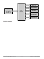
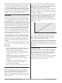
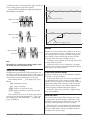
EZ-ZONE® PM PID Model 1/16 & 1/32 DIN – Input/Output
(no communications options 2 to 6)
Universal Sensor Input, Configuration Communications,
Red/Green 7-Segment Display
Output
Functions
Input
Functions
input sensor
none,
idle set point,
tune,
silence alarm,
manual/auto mode,
control outputs off,
lock keypad,
force alarm,
TRU-TUNE+® disable
loop & alarms off,
profile disable,
profile hold/resume,
profile start,
profile start/stop,
restore user settings
Network
remote user interface,
personal computer,
programmable logic
controller, humanmachine interface
Analog Input 1 thermocouple,
RTD, process (V, mV, mA, 1k potentiometer)
PID
Controller
Board
Slot A
ramp-soak
with 4 files
(optional)
Digital Input (or Output) 5
(optional) none, switch, volts dc
Digital Input (or Output) 6
(optional) none, switch, volts dc
EZ Key (1/16 DIN only)
programmable event
Supervisory
&
Power
Board
Slot C
Output 1 none, switched dc/open collector, form C mechanical (5 A) relay, form A
solid-state (0.5 A) relay, process (V, mA)
Output 2 none, switched dc, no-arc
power control (15 A), form A mechanical
(5 A) or solid-state (0.5 A) relay
off, heat, cool,
duplex, alarm,
retransmit,
event
off, heat, cool,
alarm, event
Digital Output (or Input) 5 (optional)
none, switched dc
off, heat, cool,
alarm, event
Digital Output (or Input) 6 (optional)
none, switched dc
off, heat, cool,
alarm, event
EIA 485 Communications
Standard Bus, Modbus RTU (optional)
Watlow EZ-ZONE ® PM PID Controller
•
4
•
Chapter 1 Over view
2
Chapter 2:
Install and Wire
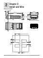
Dimensions 1/32 DIN
15.9 mm
0.63 in
53.3 mm
2.10 in
101.6 mm
4.00 in
31.2 mm
1.23 in
30.9 mm
1.22 in
Side
Front
Power
485 Comms
Dig I/O 5 & 6
C
A
Output 1
Output 2
Input 1
Back
Top
45.2 mm
(1.78 in)
22.4 mm
(0.88 in)
Recommended panel spacing
panel thickness 1.53 to 9.52 mm
(0.060 to 0.375)
21.6 mm
(0.85 in)
21.6 mm
(0.85 in)
Watlow EZ-ZONE ® PM PID Controller
•
5
•
Chapter 2 Install and Wire
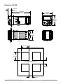
Dimensions 1/16 DIN
15.8 mm
(0.62 in)
101.6 mm
(4.00 in)
53.3 mm
(2.10 in)
53.3 mm
(2.10 in)
Side
Front
51.2 mm
(2.02 in)
L1
L3
K1
K3
99
J1
J3
CF
98
L2
L4
CD
K2
K4
CE
T1
T2
B5
S1
S2
D6
R1
R2
D5
Back
Top
45.2 mm
(1.78 in)
Recommended panel spacing
45.2 mm
(1.78 in)
panel thickness 1.53 to 9.52 mm
(0.060 to 0.375)
21.6 mm
(0.85 in)
21.6 mm
(0.85 in)
Watlow EZ-ZONE ® PM PID Controller
•
6
•
Chapter 2 Install and Wire
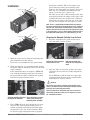
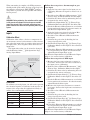
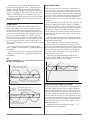
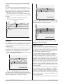
Installation
install the controller. The seal system is compressed more by mating the mounting collar
tighter to the front panel (see picture). If you can
move the case assembly back and forth in the
cutout, you do not have a proper seal.
panel
bezel
retention collar
gasket
case
The tabs on each side of the mounting collar have
teeth that latch into the ridges on the sides of the
controller. Each tooth is staggered at a different
depth from the front so that only one of the tabs,
on each side, is locked onto the ridges at a time.
Note: There is a graduated measurement difference between
the upper and lower half of the display to the panel. In order to
meet the seal requirements mentioned above, ensure that the
distance from the front of the top half of the display to the panel
is 16 mm (0.630 in.) or less, and the distance from the front of
the bottom half and the panel is 13.3 mm (0.525 in.) or less.
panel
retention collar
bezel
Removing the Mounted Controller from Its Case
gasket
1. From the controller's face, pull out the tab on
each side until you hear it click.
case
1. Make the panel cutout using the mounting template dimensions in this chapter.
Pull out the tab on each side
until you hear it click.
Insert the case assembly into the panel cutout.
2. While pressing the case assembly firmly against
the panel, slide the mounting collar over the back
of the controller.
If the installation does not require a NEMA 4X
seal, slide the mounting collar up to the back of
the panel tight enough to eliminate the spacing
between the gasket and the panel.
Grab the unit above and
below the face and pull forward.
2. Once the sides are released, grab the unit above
and below the face with two hands and pull the
unit out.
If it is difficult to pull the unit out, remove the
connectors from the back of the controller. This
should make it easier to remove.
Ó
Warning:
All electrical power to the controller and controlled circuits
must be disconnected before removing the controller from the
front panel or disconnecting other wiring.
Failure to follow these instructions may cause an electrical
shock and/or sparks that could cause an explosion in class 1,
div. 2 hazardous locations.
Slide the mounting collar over Place the blade of a screwthe back of the controller.
driver in the notch of the
mounting collar assembly.
3. For a NEMA 4X seal, place the blade of a screwdriver in the notch of the mounting collar assembly and push toward the panel while applying pressure to the face of the controller. Don't
be afraid to apply enough pressure to properly
Watlow EZ-ZONE ® PM PID Controller
•
7
•
Chapter 2 Install and Wire
Returning the Controller to its Case
1. Ensure that the orientation of the controller is
correct and slide it back into the housing.
Note: The controller is keyed so if it feels that it will not
slide back in do not force it. Check the orientation again
and reinsert after correcting.
2. Using your thumbs push on either side of the controller until both latches click.
Chemical Compatibility
This product is compatible with acids, weak alkalis,
alcohols, gamma radiation and ultraviolet radiation.
This product is not compatible with strong alkalis,
organic solvents, fuels, aromatic hydrocarbons, chlorinated hydrocarbons, esters and keytones.
Watlow EZ-ZONE ® PM PID Controller
•
8
•
Chapter 2 Install and Wire
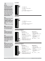
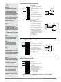
Slot A
Output
Terminal Function
Configuration
common (Any switched dc output can use this common.)
dc- (open collector)
dc+
Switched dc/open collector
output 1: PM _ _ _ C _-_ AAAA _ _
dcdc+
Switched dc
output 2: PM _ _ _ _ C-_ AAAA _ _
F1
G1
H1
voltage or current voltage +
current +
Universal Process
output 1: PM _ _ _ F _-_ AAAA _ _
L1
K1
J1
normally open
common
normally closed
Mechanical Relay 5 A, Form C
output 1: PM _ _ _ E _-_ AAAA _ _
L2
K2
normally open
common
No-arc 15 A, Form A (1/16 DIN only)
output 2: PM 6 _ _ _ H-_ AAAA _ _
L2
K2
normally open
common
Mechanical Relay 5 A, Form A
output 2: PM _ _ _ _ J-_ AAAA _ _
L2
K2
normally open
common
Solid-state Relay 0.5 A, Form A
output 1: PM _ _ _ K _-_ AAAA _ _
output 2: PM _ _ _ _ K-_ AAAA _ _
S2 (RTD) or current +, potentiometer wiper
S3 (RTD), thermocouple -, current - or volts S1 (RTD), thermocouple + or volts +
Universal Sensor
input 1: all configurations
1
2
X1
W1
Y1
W2
Y2
L1
K1
Inputs
1
T1
S1
R1
Slot A
Terminal Definitions for Slots A.
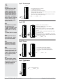
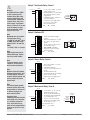
Slot C
Terminal Function
Configuration
98
99
power input: ac or dc+
power input: ac or dc-
all
CC
CA
CB
Standard Bus or Modbus RTU EIA-485 common Standard Bus or Modbus
Standard Bus or Modbus RTU EIA-485 T-/RPM _ _ _ _ _-1 AAAA _ _
Standard Bus or Modbus RTU EIA-485 T+/R+
CF
CD
CE
Standard Bus EIA-485 common
Standard Bus EIA-485 T-/RStandard Bus EIA-485 T+/R+
PM _ _ _ _ _-A AAAA _ _
B5
D6
D5
digital input-output common
digital input or output 6
digital input or output 5
PM _ _ 2 _ _-_ AAAA _ _
PM _ _ 4 _ _-_ AAAA _ _
Terminal Definitions for Slot C.
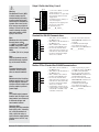
Slot C
Output 1 Output 2
Output 3 Output 4
Input 1
Input 2
Power
Slot B
Dig I/O 5 & 6 485 Comms
Slot A
Watlow EZ-ZONE ® PM PID Controller
Power
485 Comms
Output 1
Dig I/O 5 & 6
Output 2
•
9
C
Slot C
A
Slot A
Input 1
•
Chapter 2 Install and Wire
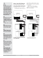
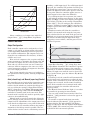
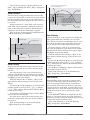
Controller
Power Supply
12 to 40VÎ (dc)
24 to 28VÅ (ac)
85 to 264VÅ (ac)
Safety Isolation
Low voltage power bus
and
internal bus
No Isolation
Digital Inputs and
Outputs 5 & 6
No Isolation
Switched DC, Open
Collector, Process Outputs
No Isolation
Analog Input 1
Safety Isolation
Mechanical Relay,
Solid-state Relay &
No-arc Relay Outputs
Low-voltage
Isolation
EIA-485
Communications Port
Low-voltage Isolation: 42V peak
Safety Isolation: 1,528VÅ (ac)
EZ-ZONE® PM isolation blocks.
Watlow EZ-ZONE ® PM PID Controller
•
10
•
Chapter 2 Install and Wire
Ó
Low Power
Slot C
98
Warning:
Use National Electric (NEC)
or other country-specific
standard wiring and safety
practices when wiring and
connecting this controller to
a power source and to electrical sensors or peripheral
devices. Failure to do so may
result in damage to equipment and property, and/or
injury or loss of life.
99
power
power
fuse
• 12 to 40VÎ (dc)
• 20 to 28VÅ (ac)
• 20 to 28VÅ (ac) Semi Sig F47
• 47 to 63 Hz
• 10VA maximum power consumption
PM _ _ (3 or 4) _ _-_ AAAA _ _
CF
CD
CE
B5
D6
D5
High Power
Note:
Maximum wire size termination and torque rating:
• 0.0507 to 3.30 mm2 (30 to
12 AWG) single-wire termination or two 1.31 mm2 (16
AWG)
• 0.8 Nm (7.0 lb.-in.) torque
Slot C
98
99
• 85 to 264VÅ (ac)
• 100 to 240VÅ (ac) Semi Sig F47
• 47 to 63 Hz
• 10VA maximum power consumption
PM _ _ (1 or 2) _ _-_ AAAA _ _
CD
CE
B5
D6
D5
Digital Input or Output 5
Digital Input
• update rate 10 Hz
• dry contact or dc voltage
Slot C
98
99
DC voltage
• maximum input 36V at 3 mA
• minimum high state 3V @ 0.25 mA
• maximum low state 2V
CF
Note:
Maintain electrical isolation
between analog input 1, digital input-outputs, switched
dc/open collector outputs and
process outputs to prevent
ground loops.
Note:
The control output common
terminal and the digital common terminal are referenced
to different voltages and
must remain isolated.
fuse
CF
Note:
Adjacent terminals may be
labeled differently, depending on the model number.
Note:
To prevent damage to the
controller, do not connect
wires to unused terminals.
power
power
CD
CE
Dry contact
• minimum open resistance 500 Ω
• maximum closed resistance 100 Ω
D6
input or output + • maximum short circuit 13 mA
B5
common -
Digital Output
• update rate 10 Hz
• output voltage 24V
• current limit, Output 5, 24 mA
maximum
• capable of driving a 3-pole
DIN-A-MITE
• open-circuit voltage 22 to
32VÎ (dc)
PM _ _ (2 or 4) _ _-_ AAAA _ _
D5
Digital Input or Output 6
Digital Input
• update rate 10 Hz
• dry contact or dc voltage
Slot C
98
99
DC voltage
• maximum input 36V at 3 mA
• minimum high state 3V @ 0.25 mA
• maximum low state 2V
CF
CD
CE
Dry contact
•
minimum open resistance 500 Ω
input or output +
D6
• maximum closed resistance 100 Ω
• maximum short circuit 13 mA
D5
B5
Watlow EZ-ZONE ® PM PID Controller
common -
•
11
•
Digital Output
• update rate 10 Hz
• output voltage 24V
• current limit, Output 6, 10 mA
maximum
• capable of driving a single-pole
DIN-A-MITE
• open-circuit voltage 22 to
32VÎ (dc)
PM _ _ (2 or 4) _ _-_ AAAA _ _
Chapter 2 Install and Wire
Ó
Input 1 Thermocouple
Slot A
L1
Warning:
Use National Electric (NEC)
or other country-specific
standard wiring and safety
practices when wiring and
connecting this controller to
a power source and to electrical sensors or peripheral
devices. Failure to do so may
result in damage to equipment and property, and/or
injury or loss of life.
•
•
•
•
20 Ω maximum source resistance
>20 MΩ input impedance
3 microampere open-sensor detection
Thermocouples are polarity sensitive. The negative lead (usually
red) must be connected to S1.
• To reduce errors, the extension wire for thermocouples must be
of the same alloy as the thermocouple.
PM _ _ _ _ _-_ AAAA _ _ (all)
K1
J1
L2
K2
T1
-
S1
+
R1
Input 1 RTD
Note:
Maximum wire size termination and torque rating:
• 0.0507 to 3.30 mm2 (30 to
12 AWG) single-wire termination or two 1.31 mm2 (16
AWG)
• 0.8 Nm (7.0 lb.-in.) torque
Slot A
Note:
To prevent damage to the
controller, do not connect
wires to unused terminals.
L1
K1
K1
J1
J1
L2
L2
K2
K2
S3
Note:
Adjacent terminals may be
labeled differently, depending on the model number.
Slot A
L1
S1
T1
S2
T1
S1
S3
S1
R1
S1
R1
3-wire
2-wire
platinum, 100 and 1,000 Ω @ 0°C
calibration to DIN curve (0.00385 Ω/Ω/°C)
20 Ω total lead resistance
RTD excitation current of 0.09 mA typical. Each
ohm of lead resistance may affect the reading by
0.03°C.
• For 3-wire RTDs, the S1 lead (usually white) must
be connected to R1.
• For best accuracy use a 3-wire RTD to compensate
for lead-length resistance. All three lead wires must
have the same resistance.
PM _ _ _ _ _-_ AAAA _ _ (all)
Input 1 Process
Slot A
Note:
Maintain electrical isolation
between analog input 1, digital input-outputs, switched
dc/open collector outputs and
process outputs to prevent
ground loops.
Slot A
L1
L1
K1
K1
J1
J1
L2
L2
K2
K2
T1
+ T1
-
- S1
+ R1
• 0 to 20 mA @ 100 Ω input impedance
• 0 to 10VÎ (dc) @ 20 kΩ input impedance
• 0 to 50 mVÎ (dc) @ 20 kΩ input impedance
• scalable
PM _ _ _ _ _-_ AAAA _ _ (all)
S1
R1
amperes
volts
Note:
The control output common
terminal and the digital common terminal are referenced
to different voltages and
must remain isolated.
•
•
•
•
Input 1 Potentiometer
Slot A
L1
K1
J1
L2
K2
• Use a 1 kΩ potentiometer.
PM _ _ _ _ _-_ AAAA _ _ (all)
T1
CW
CCW
S1
R1
Watlow EZ-ZONE ® PM PID Controller
•
12
•
Chapter 2 Install and Wire
Switched DC
• 30 mA dc maximum supply
current
• short circuit limited to <50 mA
• 22 to 32VÎ (dc) open circuit
voltage
• Use dc- and dc+ to drive external solid-state relay.
• DIN-A-MITE compatible
• single-pole: up to 4 in parallel
or 4 in series
• 2-pole: up to 2 in parallel or 2
in series
• 3-pole: up to 2 in series
Slot A
common
dc - (open collector)
dc +
X1
W1
Y1
L2
K2
T1
S1
R1
Open Collector
• 100 mA maximum output current sink
• 30VÎ (dc) maximum supply
voltage
• Any switched dc output can
use the common terminal.
• Use an external power supply
to control a dc load, with the
load positive to the positive
of the power supply, the load
negative to the open collector
and common to the power supply negative.
See Quencharc note.
PM _ _ _ C _-_ AAAA _ _
Note:
Maximum wire size termination and torque rating:
• 0.0507 to 3.30 mm2 (30 to
12 AWG) single-wire termination or two 1.31 mm2 (16
AWG)
• 0.8 Nm (7.0 lb.-in.) torque
Note:
Adjacent terminals may be
labeled differently, depending on the model number.
Switched DC
Load
+
dcW1
dc+
Y1
Internal
Circuitry
Open
Collector
Power
Supply
+
-
X1 common
W1
+
Warning:
Use National Electric (NEC)
or other country-specific
standard wiring and safety
practices when wiring and
connecting this controller to
a power source and to electrical sensors or peripheral
devices. Failure to do so may
result in damage to equipment and property, and/or
injury or loss of life.
Output 1 Switched DC/Open Collector
dc-
-
Ó
Load
dc+
Internal
Circuitry
Output 1 Mechanical Relay, Form C
Note:
To prevent damage to the
controller, do not connect
wires to unused terminals.
Slot A
normally open
common
normally closed
Note:
Maintain electrical isolation
between analog input 1, digital input-outputs, switched
dc/open collector outputs and
process outputs to prevent
ground loops.
Note:
The control output common
terminal and the digital common terminal are referenced
to different voltages and
must remain isolated.
Quencharc Note:
Switching pilot duty inductive
loads (relay coils, solenoids,
etc.) with the mechanical
relay, solid state relay or
open collector output options
requires use of an R.C. suppressor.
L1
• 5 A at 240VÅ (ac) or 30VÎ (dc)
maximum resistive load
• 20 mA at 24V minimum load
• 125 VA pilot duty at 120/240VÅ
(ac), 25 VA at 24VÅ (ac)
• 100,000 cycles at rated load
• Output does not supply power.
• for use with ac or dc
See Quencharc note.
PM _ _ _ E _-_ AAAA _ _
K1
J1
L2
K2
T1
S1
R1
Mechanical
Relay
L1
normally
open
K1 common
J1
normally
closed
Internal
Circuitry
Output 1 Universal Process
Slot A
volts or current volts +
current +
• 0 to 20 mA into 800 Ω maximum load
• 0 to 10VÎ (dc) into voltage 1
kΩ minimum load
• scalable
• output supplies power
• cannot use voltage and current
outputs at same time
• Output may be used as retransmit or control.
PM _ _ _ F _-_ AAAA _ _
F1
G1
H1
L2
K2
T1
S1
R1
Note: If output 1 is a universal process output, output 2 cannot function as a variable-time-base output.
- This note does not apply to EZ-ZONE® PM controls with firmware versions of 4 or higher.
Watlow EZ-ZONE ® PM PID Controller
•
13
•
Chapter 2 Install and Wire
Ó
Warning:
Use National Electric (NEC)
or other country-specific
standard wiring and safety
practices when wiring and
connecting this controller to
a power source and to electrical sensors or peripheral
devices. Failure to do so may
result in damage to equipment and property, and/or
injury or loss of life.
Output 1 Solid-state Relay, Form A
Slot A
normally open
common
• 0.5 A at 20 to 264VÅ (ac) maximum resistive load
• 20 VA 120/240VÅ (ac) pilot duty
• opto-isolated, without contact
suppression
• maximum off state leakage of
105 microamperes
• output does not supply power
• Do not use on dc loads.
• See Quencharc note.
PM _ _ _ K _-_ AAAA _ _
L1
K1
L2
K2
T1
S1
R1
Solid-state Relay
normally
L1 open
K1 common
Internal Circuitry
Output 2 Switched DC
Note:
Maximum wire size termination and torque rating:
• 0.0507 to 3.30 mm2 (30 to
12 AWG) single-wire termination or two 1.31 mm2 (16
AWG)
• 0.8 Nm (7.0 lb.-in.) torque
Slot A
K1
J1
dcdc+
Note:
Maintain electrical isolation
between analog input 1, digital input-outputs, switched
dc/open collector outputs and
process outputs to prevent
ground loops.
Note:
The control output common
terminal and the digital common terminal are referenced
to different voltages and
must remain isolated.
Quencharc Note:
Switching pilot duty inductive
loads (relay coils, solenoids,
etc.) with the mechanical
relay, solid state relay or
open collector output options
requires use of an R.C. suppressor.
W2
Y2
T1
S1
Note:
Adjacent terminals may be
labeled differently, depending on the model number.
Note:
To prevent damage to the
controller, do not connect
wires to unused terminals.
• 10 mA dc maximum supply
current
• short circuit limited to <50 mA
• 22 to 32VÎ (dc) open circuit
voltage
• use dc- and dc+ to drive external solid-state relay
• DIN-A-MITE compatible
• single-pole: up to 2 in series,
none in parallel
PM _ _ _ _ C-_ AAAA _ _
L1
R1
Switched DC
Load
+
dcW2
dc+
Y2
Internal
Circuitry
Output 2 No-arc Relay, Form A
Slot A
L1
• 15 A at 85 to 264VÅ (ac) resistive load only
• 1/16 DIN models only
• 2,000,000 cycle rating for no-arc
circuit
• 100 mA minimum load
• 2 mA maximum off state leakage
• Do not use on dc loads.
• Output does not supply power.
PM 6 _ _ _ H-_ AAAA _ _
K1
J1
normally open
common
L2
K2
T1
S1
R1
Output 2 Mechanical Relay, Form A
Slot A
L1
K1
J1
normally open
common
Watlow EZ-ZONE ® PM PID Controller
L2
K2
T1
S1
R1
• 5 A at 240VÅ (ac) or 30VÎ (dc)
maximum resistive load
• 20 mV at 24V minimum load
• 125 VA pilot duty @ 120/240VÅ
(ac), 25 VA at 24VÅ (ac)
• 100,000 cycles at rated load
• Output does not supply power.
• for use with ac or dc
See Quencharc note.
PM _ _ _ _ J-_ AAAA _ _
•
14
•
Mechanical
Relay
L2
normally
open
K2 common
Internal
Circuitry
Chapter 2 Install and Wire
Ó
Warning:
Use National Electric (NEC)
or other country-specific
standard wiring and safety
practices when wiring and
connecting this controller to
a power source and to electrical sensors or peripheral
devices. Failure to do so may
result in damage to equipment and property, and/or
injury or loss of life.
Output 2 Solid-state Relay, Form A
Slot A
L1
K1
J1
normally open
common
L2
K2
T1
S1
R1
• 0.5 A at 20 to 264VÅ (ac) maximum resistive load
• 20 VA 120/240VÅ (ac) pilot duty
• opto-isolated, without contact
suppression
• maximum off state leakage of
105 microamperes
• Output does not supply power.
• Do not use on dc loads.
See Quencharc note.
PM _ _ _ _ K-_ AAAA _ _
Solid-state Relay
L2
normally
open
K2 common
Internal Circuitry
Standard Bus EIA-485 Communications
Note:
Maximum wire size termination and torque rating:
• 0.0507 to 3.30 mm2 (30 to
12 AWG) single-wire termination or two 1.31 mm2 (16
AWG)
• 0.8 Nm (7.0 lb.-in.) torque
Note:
Adjacent terminals may be
labeled differently, depending on the model number.
Note:
To prevent damage to the
controller, do not connect
wires to unused terminals.
Note:
Maintain electrical isolation
between analog input 1, digital input-outputs, switched
dc/open collector outputs and
process outputs to prevent
ground loops.
Slot C
98
99
CF common
CD
CE
T-/RT+/R+
B5
D6
• Wire T-/R- to the A terminal of
the EIA-485 port.
• Wire T+/R+ to the B terminal of
the EIA-485 port.
• Wire common to the common
terminal of the EIA-485 port.
• Do not route network wires
with power wires. Connect network wires in daisy-chain fashion when connecting multiple
devices in a network.
• Do not connect more than 16
EZ-ZONE® PM controllers on a
network.
• maximum network length:
1,200 meters (4,000 feet)
• 1/8th unit load on EIA-485 bus
PM _ _ _ _ _-A AAAA _ _
D5
Modbus RTU or Standard Bus EIA-485 Communications
Slot C
98
99
CC common
CA
CB
B5
D6
D5
T-/RT+/R+
• Wire T-/R- to the A terminal of
the EIA-485 port.
• Wire T+/R+ to the B terminal of
the EIA-485 port.
• Wire common to the common
terminal of the EIA-485 port.
• Do not route network wires
with power wires. Connect network wires in daisy-chain fashion when connecting multiple
devices in a network.
• A termination resistor may be
required. Place a 120 Ω resistor
across T+/R+ and T-/R- of last
controller on network.
• Only one protocol per port is
available at a time: either Modbus RTU or Standard Bus.
• Do not connect more than 16
EZ-ZONE® PM controllers on a
Standard Bus network.
• Do not connect more than 247
EZ-ZONE® PM controllers on a
Modbus RTU network.
• maximum network length:
1,200 meters (4,000 feet)
• 1/8th unit load on EIA-485 bus.
PM _ _ _ _ _-1 AAAA _ _
Note:
The control output common
terminal and the digital common terminal are referenced
to different voltages and
must remain isolated.
Quencharc Note:
Switching pilot duty inductive
loads (relay coils, solenoids,
etc.) with the mechanical
relay, solid state relay or
open collector output options
requires use of an R.C. suppressor.
Watlow EZ-ZONE ® PM PID Controller
•
15
•
Chapter 2 Install and Wire
Ó
Warning:
Use National Electric (NEC)
or other country-specific
standard wiring and safety
practices when wiring and
connecting this controller to
a power source and to electrical sensors or peripheral
devices. Failure to do so may
result in damage to equipment and property, and/or
injury or loss of life.
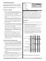
Wiring a Serial EIA-485 Network
Do not route network wires with
power wires. Connect network wires
in daisy-chain fashion when connecting multiple devices in a network.
A termination resistor may be re-
quired. Place a 120 Ω resistor across
T+/R+ and T-/R- of the last controller
on a network.
Only one protocol per port is
available at a time: either Modbus
RTU or Standard Bus.
EZ-ZONE® ST
ST_ _ - (B or F) _ M _ -_ _ _ _
EZ-ZONE® ST
ST_ _ - (B or F) _ A _ -_ _ _ _
power
supply
fuse
98
99
CC
-A
+B
power
99
CA
B5
CB
power
98
EZ-ZONE® PM
D6
-A
+B
power
power
D5
98
99
CF
CD
B5
fuse
common
Note:
To prevent damage to the
controller, do not connect
wires to unused terminals.
Note:
Maintain electrical isolation
between analog input 1, digital input-outputs, switched
dc/open collector outputs and
process outputs to prevent
ground loops.
CE
D6
Note:
Adjacent terminals may be
labeled differently, depending on the model number.
D5
Note:
Maximum wire size termination and torque rating:
• 0.0507 to 3.30 mm2 (30 to
12 AWG) single-wire termination or two 1.31 mm2 (16
AWG)
• 0.8 Nm (7.0 lb.-in.) torque
power
supply
power
power
common
EZ-ZONE® PM
98
99
power
power
com
CF
com
CC
CD
-A
CA
-A
CE
+B
CB
+B
B5
B5
D6
D6
D5
D5
PLC
RUI/Gateway
EZKB-_ A _ _- _ _ _ _
power
power
power
98
common
CF
-A
+B
CD
power
99
common
-A
+B
CE
A network using Watlow's Standard Bus
and an RUI/Gateway
A network using Modbus RTU.
Note:
The control output common
terminal and the digital common terminal are referenced
to different voltages and
must remain isolated.
Note:
Avoid continuous writes
within loops. Excessive
writes to EEPROM will cause
premature EEPROM failure.
The EEPROM is rated for
1,000,000 writes.
Watlow EZ-ZONE ® PM PID Controller
•
16
•
Chapter 2 Install and Wire
3
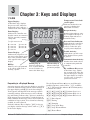
Chapter 3: Keys and Displays
1/16 DIN
Upper Display:
Temperature Units Indicator Lights:
In the Home Page, displays
the process value, otherwise
displays the value of the parameter in the lower display.
Indicates whether the temperature is displayed in
Fahrenheit or Celsius.
WATLOW
EZ-ZONE®
Output Activity:
Zone Display:
Number lights indicate activity of outputs 1 through 5. A
flashing light indicates retransmit activity.
Indicates the controller zone
that the remote user interface
(RUI) is currently communicating with.
Percent Units Indicator:
1 to 9 = zones 1 to 9
A = zone 10
b = zone 11
C = zone 12
d = zone 13
Lights when the controller is
displaying values as a percentage or when the openloop set point is displayed.
E = zone 14
F = zone 15
H = zone 16
Profile Activity:
Lower Display:
Lights when a profile is running. Flashes when a profile
is paused.
Indicates the set point or output power value during operation, or the parameter whose
value appears in the upper
display.
EZ Key:
This key can be programmed
to do various tasks, such as
starting a profile.
Communications Activity:
Infinity Key ˆ
Advance Key ‰
Press to back up one
level, or press and hold
for two seconds to return to the Home Page.
Advances through
parameter prompts.
Responding to a Displayed Message
An active message will cause the display to toggle between the normal settings and the active message in
the upper display and [Attn] in the lower display.
Your response will depend on the message and the
controller settings. Some messages, such as Ramping and Tuning, indicate that a process is underway.
If the message was generated by a latched alarm or
limit condition, the message can be cleared when the
condition no longer exists. If an alarm has silencing
enabled, it can be silenced.
Push the Advance Key to display [ignr] in the upper display and the message source (such as [Li;h1])
in the lower display.
Flashes when another device
is communicating with this
controller.
Up and Down Keys ¿ ¯
In the Home Page, adjusts
the set point in the lower display. In other pages, changes
the upper display to a higher
or lower value, or changes a
parameter selection.
Use the Up ¿ and Down ¯ keys to scroll through
possible responses, such as Clear [`CLr] or Silence
[`SiL]. Then push the Advance ‰ or Infinity ˆ key
to execute the action.
[AL;L1] [AL;L2] [AL;L3] [AL;L4] Alarm Low 1 to 4
[AL;h1] [AL;h2] [AL;h3] [AL;h4] Alarm High 1 to 4
[AL;E1] [AL;E2] [AL;E3] [AL;E4] Alarm Error 1 to 4
[Er;i1] Error Input 1
[tUn1] Tuning
[`rP1] Ramping
[LP;o1] Loop Open Error
[LP;r1] Loop Reversed Error
[`h;Er] Heater Error
Watlow EZ-ZONE ® PM PID Controller
•
17
•
Chapter 3 Keys and Displays
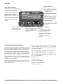
1/32 DIN
Output Activity:
Left (Upper) Display:
In the Home Page, displays
the process value, otherwise
displays the value of the parameter in the lower display.
Number lights indicate activity of outputs 1, 2, 5 and 6.
A flashing light indicates retransmit activity.
EZ -ZONE®
Right (Lower) Display:
Percent Units Indicator
1 2 5 6%
Lights when the controller is
displaying values as a percentage or when the openloop set point is displayed.
Indicates the set point or output power value during operation, or the parameter whose
value appears in the upper
display.
Profile Activity;
Lights when a profile is running. Flashes when a profile
is paused.
Advance Key ‰
Infinity Key ˆ
Advances through
parameter prompts.
Press to back up one level,
or press and hold for two
seconds to return to the
Home Page.
Responding to a Displayed Message
An active message will cause the display to toggle between the normal settings and the active message in
the upper display and [Attn] in the lower display.
Your response will depend on the message and the
controller settings. Some messages, such as Ramping and Tuning, indicate that a process is underway.
If the message was generated by a latched alarm or
limit condition, the message can be cleared when the
condition no longer exists. If an alarm has silencing
enabled, it can be silenced.
Push the Advance Key to display [ignr] in the upper display and the message source (such as [Li;h1])
in the lower display.
Up and Down Keys
¿ ¯
In the Home Page, adjusts
the set point in the lower
display. In other pages,
changes the upper display
to a higher or lower value,
or changes a parameter
selection.
Use the Up ¿ and Down ¯ keys to scroll through
possible responses, such as Clear [`CLr] or Silence
[`SiL]. Then push the Advance ‰ or Infinity ˆ key
to execute the action.
[AL;L1] [AL;L2] [AL;L3] [AL;L4] Alarm Low 1 to 4
[AL;h1] [AL;h2] [AL;h3] [AL;h4] Alarm High 1 to 4
[AL;E1] [AL;E2] [AL;E3] [AL;E4] Alarm Error 1 to 4
[Er;i1] Error Input 1
[tUn1] Tuning
[`rP1] Ramping
[LP;o1] Loop Open Error
[LP;r1] Loop Reversed Error
[`h;Er] Heater Error
Watlow EZ-ZONE ® PM PID Controller
•
18
•
Chapter 3 Keys and Displays
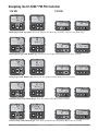
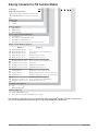
Navigating the EZ-ZONE® PM PID Controller
1/16 DIN
WATLOW
1/32 DIN
EZ-ZONE ®
[``Ai]
[`Set]
WATLOW
EZ-ZONE ®
[``70]
[``72]
EZ -ZONE ®
[`ai] [`set]
1 2 5 6%
EZ -ZONE ®
[`70] [`72]
1 2 5 6%
Home Page from anywhere: Press the Infinity Key ˆ for two seconds to return to the Home Page.
WATLOW
EZ-ZONE ®
[``70]
[``72]
WATLOW
EZ-ZONE ®
[``Ai]
[oper]
EZ -ZONE ®
[`70] [`72]
1 2 5 6%
EZ -ZONE ®
[`ai] [oper]
1 2 5 6%
Operations Page from Home Page: Press both the Up ¿ and Down ¯ keys for three seconds.
WATLOW
EZ-ZONE ®
[``70]
[``72]
WATLOW
EZ-ZONE ®
[``Ai]
[`Set]
EZ -ZONE ®
[`70] [`72]
1 2 5 6%
EZ -ZONE ®
[`ai] [`set]
1 2 5 6%
Setup Page from Home Page: Press both the Up ¿ and Down ¯ keys for six seconds.
WATLOW
EZ-ZONE ®
[``70]
[``72]
WATLOW
EZ-ZONE ®
[``P1]
[Prof]
EZ -ZONE ®
[`70] [`72]
1 2 5 6%
EZ -ZONE ®
[``P1] [Prof]
1 2 5 6%
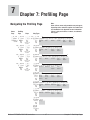
Profiling Page from Home Page: Press the Advance Key ‰ for three seconds.
WATLOW
EZ-ZONE ®
[``70]
[``72]
WATLOW
EZ-ZONE ®
[CUST]
[FCty]
EZ -ZONE ®
[`70] [`72]
1 2 5 6%
EZ -ZONE ®
[CUSt] [FCty]
1 2 5 6%
Factory Page from Home Page: Press both the Advance ‰ and Infinity ˆ keys for six seconds.
Watlow EZ-ZONE ® PM PID Controller
•
19
•
Chapter 3 Keys and Displays
4
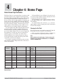
Chapter 4: Home Page
Default Home Page Parameters
The Home Page is a customized list of as many as 20
parameters that can be configured and changed in
the Custom Menu [CUSt] (Factory Page). The default
list of nine parameters below includes the Active
Process Value (value in upper display) and Active Set
Point (value in lower display). The Attention [Attn]
parameter only appears if there is an active message.
An active message could be a reported error, for example, [C;Er1] (Current Error), or it could be for information only, for example, [tUN1] (Autotuning).
Use the Advance Key ‰ to step through the other
parameters. The parameter prompt will appear in
the lower display, and the parameter value will appear in the upper display. You can use the Up ¿ and
Down ¯ keys to change the value of read-write parameters, just as you would in any other menu.
If Control Mode is set to Auto, the process value is
in the upper display and the Closed Loop Set Point
(read-write) is in the lower display.
If a profile is running, the process value is in the
upper display and the Target Set Point (read only) is
in the lower display.
Custom Menu
Number
Home
Page
Display
(defaults)
1 Upper Display
(value only)
Parameter Name
Settings
Active Process Value
If Control Mode is set to Manual, the process value is in the upper display and the output power level
(read-write) is in the lower display.
If Control Mode is set to Off, the process value is
in the upper display and [`oFF] (read only) is in the
lower display.
If a sensor failure has occurred, [----] is in the
upper display and the output power level (read-write)
is in the lower display.
Changing the Set Point
You can change the set point by using the Up ¿ and
Down ¯ keys, when a profile is not running.
If the set point is displayed and the % indicator is
lit, the controller is in open-loop (manual) mode.
Note:
Avoid continuous writes within loops. Excessive writes to EEPROM will cause premature EEPROM failure. The EEPROM is
rated for 1,000,000 writes.
Custom
Menu
Display
(defaults)
Parameter Page and Menu
[Ac;Pu]
Operations Page, Analog Iput Menu
2 Lower Display
(value only)
Active Set Point
[Ac;SP]
Operations Page, Profile Status Menu
3
[C;M1]
Control Mode
[`C;M]
Operations Page, Loop Menu
4
[h;Pr1]
Heat Power
[`h;Pr]
Operations Page, Monitor Menu
5
[C;Pr1]
Cool Power
[`C;Pr]
Operations Page, Monitor Menu
6
[AUt1]
Autotune
[`AUt]
Operations Page, Loop Menu
7
[id;S1]
Idle Set Point
[idLE]
Operations Page, Loop Menu
8
[P;St1]
Profile Start
[P;Str]
Home Page only (See Profile Page Chapter.)
9
[P;AC1]
Profile Action Request
[P;ACr]
Home Page only (See Profile Page Chapter.)
10 to 20
(skipped)
None
[nonE]
(Add parameters to the Home Page in the Custom
Menu, Factory Page.)
Default Home Page and
Attention Codes
Watlow EZ-ZONE ® PM PID Controller
•
20
•
Chapter 4 Home Page
Display
[Attn]
Parameter Name
Description
Setting
Attention
An active message will cause the
display to toggle between the
normal settings and the active
message in the upper display and
[Attn] in the lower display.
Your response will depend on the
message and the controller settings. Some messages, such as
Ramping and Tuning, indicate
that a process is underway. If
the message was generated by a
latched alarm or limit condition,
the message can be cleared when
the condition no longer exists. If
an alarm has silencing enabled, it
can be silenced.
Push the Advance Key to display
[ignr] in the upper display and
the message source (such as
[Li;h1]) in the lower display.
Range
Default
[AL;L1] [AL;L2] [AL;L3] [AL;L4]
Alarm Low 1 to 4
[AL;h1] [AL;h2] [AL;h3] [AL;h4]
Alarm High 1 to 4
[AL;E1] [AL;E2] [AL;E3] [AL;E4]
Alarm Error 1 to 4
[Er;i1] Error Input 1
[tUn1] Tuning
[`rP1] Ramping
[LP;o1] Loop Open Error
[LP;r1] Loop Reversed Error
[`h;Er] Heater Error
Appears If
an alarm or error message is active.
Use the Up ¿ and Down ¯ keys to
scroll through possible responses,
such as Clear [`CLr] or Silence
[`SiL]. Then push the Advance
‰ or Infinity ˆ key to execute
the action.
[P;St1]
Profile Start
Select a profile or step number that
will be affected by Profile Action.
0 to 40
[P;AC1]
Profile Action Request
Select the action to apply to the
profile (1 to 4) or step selected in
Profile Start.
[nonE]
[ProF}
[StEP]
[PAUS]
[rESU]
[`End]
No Action
Start a Profile
Start a Step
Pause
Resume
End
0
the controller includes
profiling (PM _ R _ _
_-_ AAAA _ _).
None
the controller includes
profiling (PM _ R _ _
_-_ AAAA _ _).
Parameters that appear only in the Home Page
Watlow EZ-ZONE ® PM PID Controller
•
21
•
Chapter 4 Home Page
5
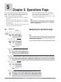
Chapter 5: Operations Page
To go to the Operations Page from the Home Page,
press both the Up ¿ and Down ¯ keys for three seconds. [``Ai] will appear in the upper display and
[oPEr] will appear in the lower display.
• Press the Up ¿ or Down ¯ key to move through
the menus.
• Press the Advance Key ‰ to move to a submenu.
• Press the Up ¿ or Down ¯ key to move through
the submenus.
• Press the Advance Key ‰ to move through the parameters of the menu or submenu.
Operations Page
Home
Page
• Press the Infinity Key ˆ to move backwards
through the levels: parameter to submenu; submenu to menu; menu to Home Page.
• Press and hold the Infinity Key ˆ for two seconds
to return to the Home Page.
Note:
Avoid continuous writes within loops. Excessive writes to EEPROM will cause premature EEPROM failure. The EEPROM is
rated for 1,000,000 writes.
Navigating the Operations Page
Parameters
[~~p~]ň [``Ai]ň
È
Ç
[~~Sp]<>Æ [oPEr]‰Æ[`ain]‰Æ[`i;Er]‰Æ[`i;Ca]‰
Hold both keys
for 3 seconds.
Analog Process
Input Menu Value
Input Error
Status
<Ç
È>
Input
Calibration
Offset
Note:
Some of these menus and parameters may not appear, depending
on the controller's options. See model number information in the
Appendix for more information.
Ɉ[`diO]ň[~~~5]ň
È
Ç
[oPEr]‰Æ[`diO]‰Æ[`do;S]‰Æ[`Ei;S]‰
If there is only one instance of a menu, no submenus will appear.
Digital In- Digital I/O 5 Output State Event Input
Status
put/Output Submenu
Menu
<Ç
È>
<Ç
È>
Ɉ Digital I/O 6 Same as above.
Submenu
Ɉ[Mon]ň
È
Ç
[oPEr]‰Æ[C;MA]‰Æ [`h;Pr]‰Æ[`C;Pr]‰Æ[`C;SP]‰Æ[`Pu;A]‰
Heat Power Cool Power Closed Loop Process
Monitor Control
Working Set Value Active
Menu Mode Active
Point
<Ç
È>
Ɉ[Loop]ň
È
Ç
[oPEr]‰Æ[`C;M]‰Æ [A;tSP]‰Æ[`AUt]‰Æ[`C;SP]‰Æ[`id;S]‰Æ[`h;Pb]‰Æ[`h;hY]‰Æ[`C;Pb]‰Æ[`C;hy]‰Æ[``ti]‰Æ[``td]‰Æ[``db]‰Æ[`o;SP]‰
Loop Menu Control
Mode
<Ç
È>
Autotune
Set Point
Autotune
Request
Closed Loop Idle Set
Set Point
Point
Heat Propor- Heat Hyster- Cool Propor- Cool Hyster- Time Integral Time Deriva- Dead Band
tional Band esis
tional Band esis
tive
Open Loop
Set Point
Ɉ[ALM]ň[~~~I]ň
È
Ç
[oPEr]‰Æ[ALM]‰Æ [`A;Lo]‰Æ[`A;hi]‰
Alarm 1
Submenu
<Ç
È>
Alarm
Menu
<Ç
È>
Alarm Low
Set Point
Alarm High
Set Point
Ɉ Alarm 2 to 4 Same as above.
Submenus
È
Ç
Ɉ[P;StA]ň
[oPEr]‰Æ[P;Str]‰Æ[P;ACr]‰Æ[`StP]‰Æ[S;tYP]‰Æ[tg;SP]‰Æ[AC;SP]‰Æ[`S;ti]‰Æ[Ent1]‰Æ[``JC]‰
Profile
Status
Menu
Profile Start Profile
Action
Request
Active Step
Active Step
Type
Active Target Active Set
Set Point
Point
Step Time
Remaining
Active Event Jump Count
Output
Remaining
(1 or 2)
<Ç
È>
Watlow EZ-ZONE ® PM PID Controller
•
22
•
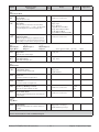
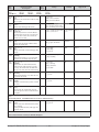
Chapter 5 Operatio ns Page
Display
Parameter name
Description
Settings
Range
Default
Appears If
[``Ai]
[oPEr]
Analog Input Menu
[`ain]
[ Ain]
Analog Input 1
Process Value
View the process value.
-1,999.000 to 9,999.000°F or units
-1,128.000 to 5,537.000°C
always
[`i;Er]
[ i.Er]
Analog Input 1
Error Status
View the cause of the most recent error. If the
[Attn] message is [Er;i1] or [Er;i2], this parameter will display the cause of the input error.
None
[nonE] None
[OPEn] Open
[Shrt] Shorted
[`E;M] Measurement Error
[E;CAL] Bad Calibration Data
[Er;Ab] Ambient Error
[E;;Rtd] RTD Lead Resistance Error
always
[`i;Ca]
[ i.CA]
Analog Input 1
Calibration Offset
Offset the input reading to compensate for lead
wire resistance or other factors that cause the input reading to vary from the actual process value.
-1,999.000 to 9,999.000°F or units 0.0
-1,110.555 to 5,555.000°C
always
[`dio]
[oPEr]
Digital Input/
Output Menu
[```5]
[`dio]
Digital Input or
Output 5
[```6]
[`dio]
Digital Input or
Output 6
(menu apprears if PM _ _ [2 or 4] _ _-_ AAAA _ _)
[`do;S]
[ do.S]
Digital Output (5 or 6)
Output State
View the state of this output.
[``on] On
[`off] Off
always
[`Ei;S]
[ Ei.S]
Digital Input (5 or 6)
Event Input Status
View this event input state.
[iACt] Inactive
[`ACt] Active
always
always
[Mon]
[oPEr]
Monitor Menu
[C;MA]
[C.MA]
Monitor
Control Mode Active
View the current control mode.
[`off] Off
[AUto] Auto
[MAn] Manual
[`h;Pr]
[ h.Pr]
Monitor
Heat Power
View the current heat output level.
0.0 to 100.0%
0.0
always
[`C;Pr]
[ C.Pr]
Monitor
Cool Power
View the current cool output level.
-100.0 to 0.0%
0.0
always
[`C;SP]
[ C.SP]
Monitor
Closed Loop Working Set Point
View the set point currently in effect.
-1,999.000 to 9,999.000°F or units 75°F or
units
-1,128.000 to 5,537.000°C
24°C
always
[`Pu;A]
[ Pv.A]
Monitor
Process Value Active
View the current filtered process value using the
control input.
-1,999.000 to 9,999.000°F or units
-1,128.000 to 5,537.000°C
always
[Loop]
[oPEr]
Loop Menu
[`C;M]
[ C.M]
Loop
Control Mode
Select the method that the controller will use to
control.
[`off] Off
[AUto] Auto (closed loop)
[MAn] Manual (open loop)
Auto
always
Note: Some values will be rounded off to fit in the four-character display. Full values can be read with other interfaces.
If there is only one instance of a menu, no submenus will appear.
Watlow EZ-ZONE ® PM PID Controller
•
23
•
Chapter 5 Operat ions Page
Display
Parameter name
Description
Settings
Range
Default
Appears If
[A;tSP]
[A.tSP}
Loop
Autotune Set Point
Set the set point that the autotune will use, as a
percentage of the current set point.
50.0 to 200.0%
90.0
Heat Algorithm
or Cool Algorithm (Setup
Page) is set to
PID.
[`AUt]
[ Aut]
Loop
Autotune Request
Start an autotune. While autotune is active, the
Home Page will display [Attn] [tUn1]. When
the autotune is complete, the message will clear
automatically.
[``no] No
[`YES] Yes
No
Heat Algorithm
or Cool Algorithm (Setup
Page) is set to
PID.
[`C;SP]
[ C.SP]
Loop
Closed Loop Set Point
Set the set point that the controller will automatically control to.
Low Set Point to High Set Point
(Setup Page)
75°F or
units
24°C
always
[`id;S]
[ id.S]
Loop
Idle Set Point
Set a closed loop set point that can be triggered by
an event state.
Low Set Point to High Set Point
(Setup Page)
75°F or
units
24°C
always
[`h;Pb]
[ h.Pb]
Loop
Heat Proportional Band
Set the PID proportional band for the heat outputs.
0 to 9,999.000°F or units
0 to 5,555.000°C
25.0°F or
units
14.0°C
Heat Algorithm
(Setup Page) is
set to PID.
[`h;hy]
[ h.hy]
Loop
Heat Hysteresis
Set the control switching hysteresis for on-off control. This determines how far into the “on” region
the process value needs to move before the output
turns on.
0 to 9,999.000°F or units
0 to 5,555.000°C
3.0°F or
units
2.0°C
Heat Algorithm
(Setup Page) is
set to On-Off.
[`C;Pb]
[ C.Pb]
Loop
Cool Proportional Band
Set the PID proportional band for the cool outputs.
0 to 9,999.000°F or units
0 to 5,555.000°C
25.0°F or
units
14.0°C
Cool Algorithm
(Setup Page) is
set to PID.
[`C;hy]
[ C.hy]
Loop
Cool Hysteresis
Set the control switching hysteresis for on-off control. This determines how far into the “on” region
the process value needs to move before the output
turns on.
0 to 9,999.000°F or units
0 to 5,555.000°C
3.0°F or
units
2.0°C
Cool Algorithm
(Setup Page) is
set to On-Off.
[``ti]
[ ti]
Loop
Time Integral
Set the PID integral for the outputs.
0 to 9,999 seconds per repeat
180.0 seconds per
repeat
Heat Algorithm
or Cool Algorithm (Setup
Page) is set to
PID.
[``td]
[ td]
Loop
Time Derivative
Set the PID derivative time for the outputs.
0 to 9,999 seconds
0.0
seconds
Heat Algorithm
or Cool Algorithm (Setup
Page) is set to
PID.
[``dB]
[ db]
Loop
Dead Band
Set the offset to the proportional band. With a
negative value, both heating and cooling outputs
are active when the process value is near the set
point. A positive value keeps heating and cooling
outputs from fighting each other.
-1,000.0 to 1,000.0°F or units
-5,555.000 to 5,555.000°C
0.0
Heat Algorithm
and Cool Algorithm (Setup
Page) are set to
PID or On-Off.
[`o;SP]
[ o.SP]
Loop
Open Loop Set Point
Set a fixed level of output power when in manual
(open-loop) mode.
-100 to 100% (heat and cool)
0 to 100% (heat only)
-100 to 0% (cool only)
0.0
always
[ALM]
[oPEr]
Alarm Menu
[```1]
[ALM]
Alarm 1
[```2]
[ALM]
Alarm 2
[```3]
[ALM]
Alarm 3
[```4]
[ALM]
Alarm 4
Note: Some values will be rounded off to fit in the four-character display. Full values can be read with other interfaces.
If there is only one instance of a menu, no submenus will appear.
Watlow EZ-ZONE ® PM PID Controller
•
24
•
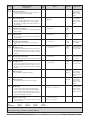
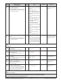
Chapter 5 Operatio ns Page
Display
Parameter name
Description
Settings
[`A;Lo]
[ A.Lo]
Alarm (1 to 4)
Low Set Point
If Alarm Type (Setup Page, Alarm Menu) is set to:
process - set the process value that will trigger a
low alarm.
deviation - set the span of units from the closed
loop set point that will trigger a low alarm.
-1,999.000 to 9,999.000°F or units 32.0°F or
units
-1,128.000 to 5,537.000°C
0.0°C
Alarm Sides
(Setup Page) is
not set to High.
[`A;hi]
[ A.hi]
Alarm (1 to 4)
High Set Point
If Alarm Type (Setup Page, Alarm Menu) is set to:
process - set the process value that will trigger a
high alarm.
deviation - set the span of units from the closed
loop set point that will trigger a high alarm.
-1,999.000 to 9,999.000°F or units 300.0°F or
units
-1,128.000 to 5,537.000°C
150.0°C
Alarm Sides
(Setup Page) is
not set to Low.
[P;Sta]
[oPEr]
Profile Status Menu (menu appears if PM _ R _ _ _-_ AAAA _ _)
Range
Default
Appears If
* Some parameters in the Profile Status Menu can be changed for the
currently running profile, but should only be changed by knowledgeable
personnel and with caution. Changing parameters via the Profile Status
Menu will not change the stored profile but will have an immediate impact on the profile that is running.
Changes made to profile parameters in the Profiling Pages will be
saved and will also have an immediate impact on the running profile.
[P;Str]
{P.Str]
Profile Status
Profile Start
Select a step or profile to load.
1 to 40
[P;ACr]
{P.ACr]
Profile Status
Profile Action Request
Select what action to apply to the currently loaded
profile.
[nonE]
[ProF]
[PAUS]
[rESU]
[`End]
[StEP]
[`StP]
[ StP]
Profile Status
Active Step
View the currently running step.
[S;typ]
[S.typ]
0 (none)
always
None
always
0 to 40
0 (none)
always
Profile Status
Active Step Type
View the currently running step type.
[UStP] Unused Step
[``ti] Time
[rAtE] Rate
[SoAH] Soak
[`W;E] Wait For Event
[W;Pr] Wait For Process
[W;bo] Wait For Both
[``JL] Jump Loop
[`End] End
Unused
Step
a profile is active.
[tg;SP]
[tg.SP]
Profile Status
*Active Target Set Point
View or change the target set point of the current
step.
-1,999.000 to 9,999.000°F or units 0.0°F or
units
-1,128.000 to 5,537.000°C
-18.0°C
a profile is active.
[AC;SP]
[AC.SP]
Profile Status
Active Set Point
Display the current set point, even if the profile is
ramping.
-1,999.000 to 9,999.000°F or units 0.0°F or
units
-1,128.000 to 5,537.000°C
-18.0°C
always
None
Profile Start
Pause
Resume
End
Start Step
Note: Some values will be rounded off to fit in the four-character display. Full values can be read with other interfaces.
If there is only one instance of a menu, no submenus will appear.
Watlow EZ-ZONE ® PM PID Controller
•
25
•
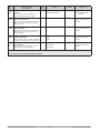
Chapter 5 Operat ions Page
Display
Parameter name
Description
Settings
Range
Default
Appears If
[`S;ti]
[ S.ti]
Profile Status
*Step Time Remaining
View or change the time remaining for the current
step.
Step is displayed in seconds. If the time exceeds
9,999 seconds, the display will show 9,999 and
remain there while the control continues to
decrement internally. Once the remaining time
is equal to or less than 9,999 the display will
represent the actual seconds remaining.
As an example, if a three-hour soak time is currently being monitored, the first value displayed
will be 9,999, and the display will remain at
9,999 until the remaining time is approximately
equal to 2 hours and 46 minutes. At this point
the display will track the actual seconds remaining.
0 to 9,999.000 seconds
0.0
always
[Ent1]
[Ent1]
[Ent2]
[Ent2]
Profile Status
*Active Event Output (1 or 2)
View or change the event output states of the current step.
[`off] Off
[``on] On
Off
always
[``JC]
[ JC]
Profile Status
Jump Count Remaining
View the jump counts remaining for the current
loop. In a profile with nested loops, this may not
indicate the actual jump counts remaining.
0 to 9,999
0
always
Note: Some values will be rounded off to fit in the four-character display. Full values can be read with other interfaces.
If there is only one instance of a menu, no submenus will appear.
Watlow EZ-ZONE ® PM PID Controller
•
26
•
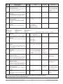
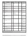
Chapter 5 Operatio ns Page
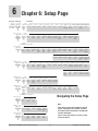
6
Chapter 6: Setup Page
Parameters
Home Page Setup Page
[~~p~]ň [~`A1]ň [~~~1]ň
Ç
È
[~~Sp]<>Æ [~set]‰Æ [~~AI]‰Æ [~sen]‰Æ[~lin]‰Æ[`Rt;l]‰Æ[`s;lo]‰Æ[`s;hi]‰Æ[`r;lo]‰Æ[`r;hi]‰Æ[`P;EE]‰Æ[`P;EL]‰Æ[`FiL]‰Æ[`i;Er]‰Æ[`dEC]‰Æ
Input 1
Submenu
<Ç
È>
Hold both keys Analog Input
for 6 seconds.
Menu
<Ç
È>
Sensor Type Linearization RTD Leads
Scale Low
Scale High
Range Low
Range High
Process
Process
Error Enable Error Low
Filter Time
Input Error
Latching
Decimal
È
Ç
Ɉ[~dio]ň [~~~5]ň
[~set]‰Æ [~dio]‰Æ [`dir]‰Æ[``Fn]‰Æ[`o;Ct]‰Æ[`o;tb]‰Æ[`o;Lo]‰Æ[`o;hi]‰Æ[``Fi]‰Æ[`leu]‰Æ[``Fn]‰Æ[``Fi]‰
In/Out 5
Submenu
<Ç
È>
Digital
Input/Output
Menu
<Ç
È>
Ɉ
In/Out 6
Submenu
Direction
Output
Function
Output
Control
Output Time Output Low Output High Output
Base
Power Scale Power Scale Function
Instance
Digital Input Digital Input Digital Input
Level
Function
Function
Instance
Same as above.
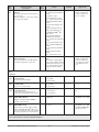
Ɉ[loop]ň
È
[~set]‰Æ [`h;Ag]‰Æ [`C;Ag]‰Æ[`C;Cr]‰Æ[t;tUn]‰Æ[t;bnd]‰Æ[`t;gn]‰Æ[t;Agr]‰Æ[`UFA]‰Æ[FAiL]‰Æ[MAn]‰Æ [`L;dE]‰Æ[`L;dt]‰Æ[`L;dd]‰Æ
Loop Menu Heat
Algorithm
<Ç
È>
Cool
Algorithm
Cool Output
Curve
TRUTUNE+™
Enable
TRUTUNE+™
Band
TRUTUNE+™
Gain
Autotune
Aggressiveness
User Failure
Action
Input Error
Failure
Manual
Power
Open Loop
Detect
Enable
Open Loop
Detect Time
Open Loop
Detect
Deviation
Ç
[``RP]‰Æ[`R;SC]‰Æ[`R;rt]‰Æ[`l;sp]‰Æ[`h;SP]‰ [sp;Lo]‰Æ[SP;hi]‰
Ramp Action Ramp Scale
Ramp Rate
Low Set
Point
High Set
Point
Set Point Low Set Point High
Limit Open Limit Open
Loop
Loop
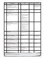
Ɉ[OtPt]ň [~~~1]ň
È
[~set]‰Æ [OtPt]‰Æ [~o;tY]‰Æ[~~Fn]‰Æ[~r;Sr]‰Æ[~~Fi]‰Æ[`S;Lo]‰Æ[`S;hi]‰Æ[`r;Lo]‰Æ[`r;hi]‰Æ[`o;Lo]‰Æ[`o;hi]‰ [`o;CA]‰Æ[``Fn]‰Æ
Output Menu
<Ç
È>
Output 1
Submenu
<Ç
È>
Output
Type
Output
Function
Retransmit
Source
Output
Function
Instance
Scale Low
Scale High
Range Low
Range High
Output Low Output High Calibration
Power Scale Power Scale Offset
Output
Function
Ç
[``Fi]‰Æ[`o;Ct]‰Æ[`o;tb]‰Æ[`o;Lo]‰Æ[`o;hi]‰
Output
Function
Instance
Output
Control
Output Time Output Low Output High
Base
Power Scale Power Scale
Ɉ[OtPt]ň [~~~2ň
È
Ç
[~set]‰Æ [OtPt]‰Æ [``Fn]‰Æ[``Fi]‰Æ[`o;Ct]‰Æ[`o;tb]‰Æ[`o;Lo]‰Æ[`o;hi]‰
Output Menu
<Ç
È>
Output2
Submenu
<Ç
È>
Output
Function
Output
Function
Instance
Output
Control
Output Time Output Low Output High
Base
Power Scale Power Scale
È
Ç
Ɉ[ALM]ň [~~~1]ň
[~set]‰
[ALM]‰Æ [`A;ty]‰Æ[`sr;a]‰Æ[`A;hy]‰Æ[`A;Lg]‰Æ[`A;Sd]‰Æ[`A;La]‰Æ[~A;bL]‰Æ[`A;Si]‰Æ[A;dsp]‰Æ[`A;dl]‰
Alarm Menu
<Ç
È>
Alarm 1
Submenu
<Ç
È>
Alarm Type
Alarm
Source
Alarm
Hysteresis
Alarm Logic
Alarm Sides
Alarm
Latching
Alarm 2 to 4
Ɉ Submenus Same as above.
Alarm
Blocking
Alarm
Silencing
Alarm
Display
Alarm Delay
Navigating the Setup Page
Ɉ[`FUn]ň
È
Ç
[~SEt]‰Æ [`leu]‰Æ [``Fn]‰Æ[``Fi]‰
Function Key Digital Input Digital Input Function
Level
Function
Instance
Menu
<Ç
È>
Note:
È
Ç
Ɉ[gl;bl]ň
[~SEt]‰Æ [`C_F]‰Æ [AC;LF]‰Æ[p;typ]‰Æ[`gse]‰Æ[~gsd]‰
Global Menu Display Units AC Line
<Ç
È>
Profile Type
Frequency
Some of these menus and parameters may not
appear, depending on the controller's options.
See model number information in the Appendix
for more information.
Guaranteed Guaranteed
Soak Enable Soak Deviation
È
Ç
Ɉ[CoM]ň
[~SEt]‰Æ [PCoL]‰Æ [`Ad;S]‰Æ[Ad;M]‰Æ [bAUd]‰Æ[`PAr]‰
Communica- Protocol
tions Menu
<Ç
È>
Address
Standard
Bus
Address
Modbus
Baud Rate
Modbus
Watlow EZ-ZONE ® PM PID Controller
If there is only one instance of a menu, no submenus will appear.
Parity
Modbus
•
27
•
Chapter 6 Setup Page
• Press the Advance Key ‰ to move through the parameters of the menu or submenu.
• Press the Infinity Key ˆ to move backwards
through the levels: parameter to submenu; submenu to menu; menu to Home Page.
• Press and hold the Infinity Key ˆ for two seconds
to return to the Home Page.
To go to the Setup Page from the Home Page, press
both the Up ¿ and Down ¯ keys for six seconds.
[``Ai] will appear in the upper display and [`Set]
will appear in the lower display.
• Press the Up ¿ or Down ¯ key to move through
the menus.
• Press the Advance Key ‰ to move to a submenu.
• Press the Up ¿ or Down ¯ key to move through
the submenus.
Display
Parameter Name
Description
Note: Avoid continuous writes within loops. Excessive writes to
EEPROM will cause premature EEPROM failure. The EEPROM
is rated for 1,000,000 writes.
Settings
Range
Default
Appears If
[``Ai]
[`Set]
Analog Input Menu
[`Sen]
[ SEn]
Input 1
Sensor Type
Set the analog sensor type to match the
device wired to this input.
Note: There is no open-sensor detection for
process inputs.
[`oFF] Off
[``tC] Thermocouple
[`mu] Millivolts
[uolT] Volts dc
[`MA] Milliamps dc
[r0;1H] RTD 100 Ω
[r1;0H] RTD 1,000 Ω
[`Pot] Potentiometer 1 kΩ
Thermocouple
always
J
Sensor Type is set to
Thermocouple.
[`Lin]
[ Lin]
Input 1
Linearization
Set the linearization to match the thermocouple type wired to this input.
For example, select [```H] for a type K
thermocouple.
[```b] B
[```C] C
[```d] D
[```E] E
[```F] F
[```J] J
[`Rt;L]
[ rt.L]
Input 1
RTD Leads
Set to match the number of leads on the
RTD wired to this input.
[```2] 2
[```3] 3
2
Sensor Type is set to
RTD 100 Ω or RTD
1,000 Ω.
[`S;Lo]
[ S.Lo]
Input 1
Scale Low
Set the low scale for process inputs. This
value, in millivolts, volts or milliamps, will
correspond to the Range Low displayed by
the controller.
-100.0 to 1,000.0
0.0
Sensor Type is set to Millivolts, Volts, Milliamps
or Potentiometer 1 kΩ.
[`S;hi]
[ S.hi]
Input 1
Scale High
Set the high scale for process inputs. This
value, in millivolts, volts or milliamps, will
correspond to the Range High displayed by
the controller.
-100.0 to 1,000.0
20.0
Sensor Type is set to Millivolts, Volts, Milliamps
or Potentiometer 1 kΩ.
[`r;Lo]
[ r.Lo]
Input 1
Range Low
Set the low range for the displayed process
input units.
-1,999.000 to 9,999.000
0.0
Sensor Type is set to Millivolts, Volts, Milliamps
or Potentiometer 1 kΩ.
[`r;hi]
[ r.hi]
Input 1
Range High
Set the high range for the displayed process input units.
-1,999.000 to 9,999.000°C
9,999.0
Sensor Type is set to Millivolts, Volts, Milliamps
or Potentiometer 1 kΩ.
[`P;EE]
[ P.EE]
Input 1
Process Error Enable
Turn the Process Error Low feature on or
off.
[`off] Off
[Low] Low
Off
Sensor Type is set to Millivolts, Volts, Milliamps
or Potentiometer 1 kΩ.
[```H] K
[```n] N
[```r] R
[```S] S
[```t] T
Note: Some values will be rounded off to fit in the four-character display. Full values can be read with other interfaces.
If there is only one instance of a menu, no submenus will appear.
Watlow EZ-ZONE ® PM PID Controller
•
28
•
Chapter 6 Setup Page
Display
Parameter Name
Description
[`P;EL]
[ P.EL]
Input 1
Process Error Low
If the process value drops below this value,
it will trigger an input error.
-100.0 to 1,000.0
0.0
Sensor Type is set to Millivolts, Volts, Milliamps
or Potentiometer 1 kΩ,
and Error Enable is set
to Low.
[`FiL]
[ FiL]
Input 1
Filter Time
Filtering smooths out the process signal to
both the display and the input. Increase
the time to increase filtering.
0.0 to 60.0 seconds
0.5
always
[`i;Er]
[ i.Er]
Input 1
Error Latching
Turn input error latching on or off. If
latching is on errors must be manually
cleared.
[`off] Off
[``on] On
Off
always
[`dEC]
[ dEC]
Input 1
Decimal
Set the precision of the displayed value.
[```0] Whole
[``0;0] Tenths
[`0;00] Hundredths
[0;000] Thousandths
Whole
always
[`dio]
[`Set]
Digital Input/
Output Menu
[```5]
[`dio]
Digital Input or
Output 5
Settings
Range
[```6]
[`dio]
Digital Input or
Output 6
Default
Appears If
(menu apprears it PM _ _ [2 or 4] _ _-_ AAAA _ _)
[`dir]
[ dir]
Digital Input/Output (5 or 6)
Direction
Set the function to an input or output.
[OtPt] Output
[``in] Input Voltage
[iCon] Input Dry Contact
Output
always
[``Fn]
[ Fn]
Digital Output (5 or 6)
Function
Select what function will drive this output.
[`oFF] Off
[CooL] Cool
[hEAt] Heat
[ALM] Alarm
[`Ent] Event
Off
Direction is set to Output.
[`o;Ct]
[ o.Ct]
Digital Output (5 or 6)
Control
Set the output control type. This parameter is only used with PID control, but can
be set anytime.
[`Ftb] Fixed Time Base
[`utb] Variable Time Base
Fixed Time
Base
Direction is set to Output.
[`o;tb]
[ o.tb]
Digital Output (5 or 6)
Time Base
Set the time base for fixed-time-base control.
0.1 to 60.0 seconds (solid0.1 sec. [SSR & Control is set to Fixed
state relay or switched dc)
sw dc]
Time Base.
5.0 to 60.0 seconds (mechani- 20.0 sec.
cal relay or no-arc power
[mech, relay,
control)
no-arc]
[`o;Lo]
[ o.Lo]
Digital Output (5 or 6)
Low Power Scale
The power output will never be less than
the value specified and will represent the
value at which output scaling begins.
0.0 to 100.0%
0.0%
Direction is set to Output
and Source is set to
Heat or Cool.
[`o;hi]
[ o.hi]
Digital Output (5 or 6)
High Power Scale
The power output will never be greater
than the value specified and will represent
the value at which output scaling stops.
0.0 to 100.0%
100.0%
Direction is set to Output
and Source is set to
Heat or Cool.
[``Fi]
[ Fi]
Digital Output (5 or 6)
Function Instance
Select which source instance will drive the
output.
1 to 4
1 (output 5)
2 (output 6)
Direction is set to Output, and there is more
than one instance of the
Function selection.
[`leu]
[ LEv]
Digital Input (5 or 6)
Level
Select what action will be interpreted as a
true state.
[high] High
[Low] Low
High
Direction is set to Input
Voltage or Input Dry
Contact.
Note: Some values will be rounded off to fit in the four-character display. Full values can be read with other interfaces.
If there is only one instance of a menu, no submenus will appear.
Watlow EZ-ZONE ® PM PID Controller
•
29
•
Chapter 6 Setup Page
Display
[``Fn]
[ Fn]
Parameter Name
Description
Settings
Digital Input (5 or 6)
Function
Select the function that will be triggered
by a true state.
Functions respond to a level state change
or an edge level change.
Range
Default
None
[none] None
[idLE] Idle Set Point Enable
(level)
[tUnE] Tune (edge)
[ALM] Alarm Reset (edge)
[`SiL] Silence Alarms (edge)
[MAn] Manual/Auto Mode
(level)
[`oFF] Control Outputs Off
(level)
[P;LoC] Lock Keypad (level)
[`F;AL] Force Alarm (level)
Appears If
Direction is set to Input
Voltage or Input Dry
Contact, and the feature is available.
[`t;dA] TRU-TUNE+® Disable (level)
[`AoF] Alarm Outputs &
Control Loop Off (level)
[usr;r] Restore User Settings
(edge)
[P;diS] Profile Disable (level)
[P;hoL] Profile Hold/Resume
(level)
[ProF] Profile Start Number
(edge)
[P;StS] Profile Start/Stop
(level)
[LMr] Limit Reset (edge)
[``Fi]
[ Fi]
Digital Input (5 or 6)
Function Instance
Select which instance of the Event Function will be triggered by a true state.
0 All Instances (except pro1
files)
(For example, if Digital Function is set to Silence Alarms
and Function Instance is set
to 0, then this digital input
will silence both alarms.)
1 to 4
Direction is set to Input
Voltage or Input Dry
Contact, and there is
more than one instance
of the Function selection.
[Loop]
[`Set]
Loop Menu
[`h;Ag]
[ h.Ag]
Loop
Heat Algorithm
Set the heat control method.
[`oFF] Off
[`Pid] PID
[on;of] On-Off
PID
always
[`C;Ag]
[ C.Ag]
Loop
Cool Algorithm
Set the cool control method.
[`oFF] Off
[`Pid] PID
[on;of] On-Off
Off
always
[`C;Cr]
[ C.Cr]
Loop
Cool Output Curve
Select a special cool output curve to
change the responsiveness of the system.
[`oFF] Off
[`Cr;A] Curve A
[`Cr;b] Curve B
Off
Cool Algorithm is set to
Off.
[t;tUn]
[t.tUn]
Loop
TRU-TUNE+® Enable
Enable or disable the TRU-TUNE+®
adaptive tuning feature.
[``no] No
[`YES} Yes
No
Cool Algorithm or Heat
Algorithm is set to PID.
[t;bnd]
[t.bnd]
Loop
TRU-TUNE+® Band
Set the range, centered on the set point,
within which TRU-TUNE+® will be in effect. Use this function only if the controller
is unable to adaptive tune automatically.
0 Auto
1 to 1,000
0
Cool Algorithm or Heat
Algorithm is set to PID
and TRU-TUNE+® Enable is set to Yes.
Note: Some values will be rounded off to fit in the four-character display. Full values can be read with other interfaces.
If there is only one instance of a menu, no submenus will appear.
Watlow EZ-ZONE ® PM PID Controller
•
30
•
Chapter 6 Setup Page
Display
Parameter Name
Description
Settings
Range
Default
Appears If
[`t;gn]
[ t.gn]
Loop
TRU-TUNE+® Gain
Select the responsiveness of the TRUTUNE+® adaptive tuning calculations.
More responsiveness may increase overshoot.
1 to 6 Most to least responsive
3
Cool Algorithm or Heat
Algorithm is set to PID
and TRU-TUNE+® Enable is set to Yes.
[t;Agr]
[t.Agr]
Loop
Autotune Aggressiveness
Select the aggressiveness of the autotuning calculations.
[Undr] Under damped
[Crit] Critical damped
[ouEr] Over damped
Critical
Cool Algorithm or Heat
Algorithm is set to PID.
[`UFA]
[ UFA]
Loop
User Failure Action
Select what the controller outputs will do
when the user switches control to manual
mode.
[`oFF] Off, sets output power Off
to 0%
[bPLS] Bumpless, maintains
same output power, if it was
less than 75% and stable,
otherwise 0%
[MAn] Manual Fixed, sets
output power to Manual
Power setting
[USEr] User, sets output
power to last open-loop set
point the user entered
always
[FAiL]
[FAiL]
Loop
Input Error Failure
Select what the controller outputs will do
when an input error switches control to
manual mode.
[`oFF] Off, sets output power Off
to 0%
[bPLS] Bumpless, maintains
same output power, if it was
less than 75% and stable,
otherwise 0%
[MAn] Manual Fixed, sets
output power to Manual
Power setting
[USEr] User, sets output
power to last open-loop set
point the user entered
always
[MAn]
[MAn]
Loop
Manual Power
Set the manual output power level that
will take effect if an input error failure
occurs.
Set Point Open Loop Limit
0.0
Low to Set Point Open Loop
Limit High (Setup Page)
Input Error Failure is set
to Manual Fixed.
[`L;dE]
[ L.dE]
Loop
Open Loop Detect Enable
Turn on the open-loop detect feature to
monitor a closed-loop operation for the appropriate response.
[``no] No
[`YES} Yes
No
controller is equipped
with a current transformer input (PM6 _ _ _
_ - _T _ _ _ _ _).
[`L;dt]
[ L.dt]
Loop
Open Loop Detect Time
The Open Loop Detect Deviation value
must occur for this time period to trigger
an open-loop error.
0 to 3,600 seconds
240
Open Loop Detect Enable
is set to Yes.
[`L;dd]
[ L.dd]
Loop
Open Loop Detect Deviation
Set the value that the process must deviate from the set point to trigger an openloop error.
-1,999.000 to 9,999.000°F or
units
-1,110.555 to 5,555.000°C
10.0°F or units Open Loop Detect Enable
is set to Yes.
-6.0°C
[``rP]
[ rP]
Loop
Ramp Action
Select when the controller's set point will
ramp to the defined end set point.
[`oFF]
[`Str]
[StPt]
[both]
Off
always
[`r;SC]
[ r.SC]
Loop
Ramp Scale
Select the scale of the ramp rate.
[hoUr] Hours
[Min] Minutes
Minutes
Ramp Action is set to
Startup, Set Point or
Both.
Off
Startup
Set Point Change
Both
Note: Some values will be rounded off to fit in the four-character display. Full values can be read with other interfaces.
If there is only one instance of a menu, no submenus will appear.
Watlow EZ-ZONE ® PM PID Controller
•
31
•
Chapter 6 Setup Page
Display
Parameter Name
Description
[`r;rt]
[ r.rt]
Loop
Ramp Rate
Set the rate for the set point ramp. Set
the time units for the rate with the Ramp
Scale parameter.
0 to 9,999°F or units
0 to 5,555.000°C
1.0°F or units
1.0°C
[`L;SP]
[ L.SP]
Loop
Low Set Point
Set the low end of the set point range.
-1,999.000 to 9,999.000°F or
units
-1,128.000 to 5,537.000°C
-1,999.000°F or always
units
-1,128.0°C
[`h;SP]
[ h.SP]
Loop
High Set Point
Set the high end of the set point range.
-1,999.000 to 9,999.000°F or
units
-1,128.000 to 5,537.000°C
9,999.000°F or
units
5,537.000°C
always
[SP;Lo]
[SP.Lo]
Loop
Set Point Low Limit Open Loop
Set the minimum value of the open-loop
set point range.
-100 to 100%
-100
always
[SP;hi]
[SP.hi]
Loop
Set Point High Limit Open Loop
Set the maximum value of the open-loop
set point range.
-100 to 100%
100
always
[otpt]
[`Set]
Output Menu
[```1]
[otpt]
Output 1
[```2]
[otPt]
Output 2
Settings
Range
Default
Appears If
Ramp Action is set to
Startup, Set Point or
Both.
(check model number for output information)
[`o;ty]
[ o.ty]
Output 1
Type
Select whether the process output will operate in volts or milliamps.
[uoLt] Volts
[`MA] Milliamps
Volts
[``Fn]
[ Fn]
Output 1
Function
Select what function will drive this output.
[`oFF] Off
[hEAt] Heat
[CooL] Cool
[dUPL] Duplex
[ALM] Alarm
[`Ent] Event
[rMt] Retransmit
Heat (output 1) a process output (PM _ _
_ F _-_ AAAA _ _)
Off (output 2)
[`r;Sr]
[ r.Sr]
Output 1
Retransmit Source
Select the value that will be retransmitted.
[``Ai] Analog Input
[StPt] Set Point
[CUrr] Current
Analog Input
a process output (PM _ _
_ F _-_ AAAA _ _) and
Function is set to Retransmit.
[``Fi]
[ Fi]
Output 1
Function Instance
Select which source instance will drive the
output.
1 to 4
1
a process output (PM _
_ _ F _-_ AAAA _ _) and
there is more than one
instance of the Function
selection.
[`S;Lo]
[ S.Lo]
Output 1
Scale Low
Set the minimum value of the process output range in electrical units.
0.00 to 20.00
0.00
a process output (PM _ _
_ F _-_ AAAA _ _)
[`S;hi]
[ S.hi]
Output 1
Scale High
Set the maximum value of the process output range in electrical units.
0.00 to 20.00
10.00
a process output (PM _ _
_ F _-_ AAAA _ _)
[`r;Lo]
[ r.Lo]
Output 1
Range Low
Set the minimum value of the retransmit
value range in process units. When the
retransmit source is at this value, the
retransmit output will be at its Scale Low
value.
-1,999.000 to 9,999.000°F or
units
-1,128.000 to 5,537.000°C
0.0°F or units
-18.0°C
a process output (PM _ _
_ F _-_ AAAA _ _) and
Function is set to Retransmit.
a process output (PM _ _
_ F _-_ AAAA _ _)
Note: Some values will be rounded off to fit in the four-character display. Full values can be read with other interfaces.
If there is only one instance of a menu, no submenus will appear.
Watlow EZ-ZONE ® PM PID Controller
•
32
•
Chapter 6 Setup Page
Display
Parameter Name
Description
Settings
Range
Default
Appears If
[`r;hi]
[ r.hi]
Output 1
Range High
Set the maximum value of the retransmit
value range in process units. When the
retransmit source is at this value, the retransmit output will be at its Scale High
value.
-1,999.000 to 9,999.000°F or
units
-1,128.000 to 5,537.000°C
9,999.0°F or
units
5,537.0°C
a process output (PM _ _
_ F _-_ AAAA _ _) and
Function is set to Retransmit.
[`o;Lo]
[ o.Lo]
Output 1
Low Power Scale
Set the minimum value of the output
range.
0.0 to 100.0%
0.0
a process output (PM _ _
_ F _-_ AAAA _ _) and
Function is set to Heat
or Cool.
[`o;hi]
[ o.hi]
Output 1
High Power Scale
Set the maximum value of the output
range.
0.0 to 100.0%
100.0
a process output (PM _ _
_ F _-_ AAAA _ _) and
Function is set to Heat
or Cool.
[`o;CA]
[ o.CA]
Output 1
Calibration Offset
Set an offset value for a process output.
-1,999.000 to 9,999.000°F or
units
-1,110.555 to 5,555.000°C
0.0
a process output (PM _ _
_ F _-_ AAAA _ _)
[``Fn]
[ Fn]
Output (1or 2)
Function
Select what function will drive this output.
Heat
[`oFF] Off
Alarm
[hEAt] Heat
[CooL] Cool
[ALM] Alarm
[`Ent] Event
[LiM] Limit (outputs 3 & 4)
a time-proportioned output (solid-state relay,
switched dc or mechanical relay)
[``Fi]
[ Fi]
Output (1 or 2)
Function Instance
Select which source instance will drive the
output.
1 to 4
1
a time-proportioned output (solid-state relay,
switched dc or mechanical relay), and there is
more than one instance
of the Function selection.
[`o;Ct]
[ o.Ct]
Output (1 or 2)
Control
Set the output control type. This parameter is only used with PID control, but can
be set anytime.
[`Ftb] Fixed Time Base
[`utb] Variable Time Base
Fixed Time
Base
a time-proportioned output (solid-state relay,
switched dc or mechanical relay)
If output 1 is a universal
process output (PM _ _
_ F _- _ AAAA _ _), output 2 cannot function
as a variable-time-base
output.
[`o;tb]
[ o.tb]
Output (1 or 2)
Time Base
Set the time base for fixed-time-base control.
0.1 to 60.0 seconds (solid0.1 sec. [SSR & a time-proportioned
state relay or switched dc)
sw dc]
output (solid-state
relay, switched dc or
5.0 to 60.0 seconds (mechani- 20.0 sec.
mechanical relay) and
cal relay & no-arc power
[mech. relay
Control is set to Fixed
control)
& no-arc]
Time Base.
[`o;Lo]
[ o.Lo]
Output (1 or 2)
Low Power Scale
The power output will never be less than
the value specified and will represent the
value at which output scaling begins.
0.0 to 100.0%
0.0%
a time-proportioned output (solid-state relay,
switched dc or mechanical relay) and Source is
set to Heat or Cool.
[`o;hi]
[ o.hi]
Output (1 or 2)
High Power Scale
The power output will never be greater
than the value specified and will represent
the value at which output scaling stops.
0.0 to 100.0%
100.0%
a time-proportioned output (solid-state relay,
switched dc or mechanical relay) and Source is
set to Heat or Cool.
Note: Some values will be rounded off to fit in the four-character display. Full values can be read with other interfaces.
If there is only one instance of a menu, no submenus will appear.
Watlow EZ-ZONE ® PM PID Controller
•
33
•
Chapter 6 Setup Page
Display
Parameter Name
Description
[Alm]
[`Set]
Alarm Menu
[```1]
[Alm]
Alarm 1
[```2]
[Alm]
Alarm 2
Settings
[```3]
[Alm]
Alarm 3
Range
Default
Appears If
[```4]
[Alm]
Alarm 4
[`A;ty]
[ A.ty]
Alarm (1 to 4)
Type
Select how the alarm will or will not track
the set point.
[`oFF] Off
[PR;AL] Process Alarm
[dE;AL] Deviation Alarm
[`sr;a]
[ Sr.A]
Alarm (1 to 4)
Source
Select what will trigger this alarm.
Analog Input
[``Ai] Analog Input
[PWr] Power (process only)
[CUrr] Current (process only)
always
[`A;hy]
[ A.hy]
Alarm (1 to 4)
Hysteresis
Set the hysteresis for an alarm. This determines how far into the safe region the
process value needs to move before the
alarm can be cleared.
0.001 to 9,999.000°F or units
0.001 to 5,555.000°C
1.0°F or units
1.0°C
always
[`A;Lg]
[ A.Lg]
Alarm (1 to 4)
Logic
Select what the output condition will be
during the alarm state.
[`AL;C] Close On Alarm
[`AL;o] Open On Alarm
Close On
Alarm
always
[`A;Sd]
[ A.Sd]
Alarm (1 to 4)
Sides
Select which side or sides will trigger this
alarm.
[both] Both
[high] High
[LoW] Low
Both
always
[`A;LA]
[ A.LA]
Alarm (1 to 4)
Latching
Turn alarm latching on or off. A latched
alarm has to be turned off by the user.
[nLAt] Non-Latching
[`LAt] Latching
Non-Latching
always
[`A;bL]
[ A.bL]
Alarm (1 to 4)
Blocking
Select when an alarm will be blocked.
After startup and/or after the set point
changes, the alarm will be blocked until
the process value enters the normal range.
[`oFF]
[`Str]
[StPt]
[both]
Off
always
[`A;Si]
[ A.Si]
Alarm (1 to 4)
Silencing
Turn alarm silencing on to allow the user
to disable this alarm.
[`oFF] Off
[``on] On
Off
always
[A;dSP] Alarm (1 to 4)
[A.dSP] Display
Display an alarm message when an alarm
is active.
[`oFF] Off
[``on] On
On
always
0 to 9,999 seconds
0
always
High
always
[`A;dL]
[ A.dL]
Alarm (1 to 4)
Delay
Set the time the alarm will be delayed
after the process value exceeds the alarm
set point.
Off
Startup
Set Point
Both
Off
always
[`FUn]
[`Set]
Function Key Menu (1/32 DIN models do not have a Function Key.)
[`leu]
[ LEv]
Function Key
Level
Select what state the Function Key will be
in at startup.
Pressing the Function Key will toggle the
selected action.
[high] High
[Low] Low
Note: Some values will be rounded off to fit in the four-character display. Full values can be read with other interfaces.
If there is only one instance of a menu, no submenus will appear.
Watlow EZ-ZONE ® PM PID Controller
•
34
•
Chapter 6 Setup Page
Display
[``Fn]
[ Fn]
Parameter Name
Description
Settings
Function Key
Digital Input Function
Program the EZ Key to trigger an action.
Functions respond to a level state change
or an edge level change.
Range
Default
None
[none] None
[idLE] Idle Set Point Enable
(level)
[tUnE] Tune (edge)
[ALM] Alarm Reset (edge)
[`SiL] Silence Alarms (edge)
[MAn] Manual/Auto Mode
(level)
[`oFF] Control Outputs Off
(level)
[P;LoC] Lock Keypad (level)
[`F;AL] Force Alarm (level)
Appears If
always, but only the
available features can be
selected.
[`t;dA] TRU-TUNE+® Disable (level)
[`AoF] Alarm Outputs &
Control Loop Off (level)
[usr;r] Restore User Settings
(edge)
[P;diS] Profile Disable (level)
[P;hoL] Profile Hold/Resume
(level)
[ProF] Profile Start Number
(edge)
[P;StS] Profile Start/Stop
(level)
[LMr] Limit Reset (edge)
[``Fi]
[ Fi]
Function Key
Instance
Select which instance the EZ Key will affect. If only one instance is available, any
selection will affect it.
0 All Instances (except Pro0
file)
(For example, if Digital Function is set to Silence Alarms
and Function Instance is set
to 0, then the digital input
would silence both alarms.)
1 to 4
there is more than one
instance of the Digital
Input Function selection.
[```F] °F
[```C] °C
°F
always
[``50] 50 Hz
[``60] 60 Hz
60 Hz
always
[gLbL]
[`Set]
Global Menu
[`C_F]
[ C_F]
Global
Display Units
Select which units will be displayed.
[AC;LF] Global
[AC.LF] AC Line Frequency
Set the frequency to the applied ac line
power source.
[P;typ]
[P.tyP]
Global
Profile Type
Set the profile startup to be based on a set
point or a process value.
[StPt] Set Point
[`Pro] Process
Set Point
the controller includes
profiling (PM _ R _ _ _-_
AAAA _ _).
[`GSE]
[ gSE]
Global
Guaranteed Soak Enable
Enables the guaranteed soak deviation
function in profiles.
[`oFF] Off
[``on] On
Off
the controller includes
profiling (PM _ R _ _ _-_
AAAA _ _).
[`GSd]
[ gSd]
Global
Guaranteed Soak Deviation
Set the value of the deviation band that
will be used in all profile step types. The
process value must enter the deviation
band before the step can proceed.
0.0 to 9,999.000°F or units
0.0 to 5,555.000°C
10.0°F or units the controller includes
profiling (PM _ R _ _ _-_
6.0°C
AAAA _ _).
[CoM]
[`SEt]
Communications Menu
Note: Some values will be rounded off to fit in the four-character display. Full values can be read with other interfaces.
If there is only one instance of a menu, no submenus will appear.
Watlow EZ-ZONE ® PM PID Controller
•
35
•
Chapter 6 Setup Page
Display
Parameter Name
Description
Settings
Range
Default
Appears If
[PCoL]
[PCoL]
Communications
Protocol
Set the protocol of this controller to the
protocol that this network is using.
[`Std] Standard Bus
[Mod] Modbus RTU
Modbus
the controller includes
Modbus RTU (PM6 _ _
_ _-1 AAAA _ _).
[`Ad;S]
[ Ad.S]
Communications
Address Standard Bus
Set the network address of this controller.
Each device on the network must have a
unique address.
1 to 16
1
always
Range depends on the
model.
[Ad;M]
[Ad.M]
Communications
Address Modbus
Set the network address of this controller.
Each device on the network must have a
unique address.
1 to 247
1
Protocol is set to Modbus
Range depends on the
model.
[bAUd]
[bAUd]
Communications
Baud Rate Modbus
Set the speed of this controller's communications to match the speed of the network.
9,600
19,200
38,400
9,600
always
Range depends on the
model.
[`PAr]
[ PAr]
Communications
Parity Modbus
Set the parity of this controller to match
the parity of the serial network.
[none] None
[EuEn] Even
[`odd] Odd
None
always
Range depends on the
model.
Note: Some values will be rounded off to fit in the four-character display. Full values can be read with other interfaces.
If there is only one instance of a menu, no submenus will appear.
Watlow EZ-ZONE ® PM PID Controller
•
36
•
Chapter 6 Setup Page
7
Chapter 7: Profiling Page
Navigating the Profiling Page
Profiling
Page
Home
Page
[~~p~]ˆ [~~p1]ˆ
[~~Sp]‰ [FiLe]‰
Hold key for 3
seconds.
Profile 1
<
>
ˆ[``P2]ˆ
[FiLE]‰
Profile 2
<
>
ˆ[``P3]ˆ
[FiLE]‰
Profile 3
<
>
ˆ[``P4]ˆ
[FiLE]‰
Profile 4
<
>
Steps
[~~`1]
[``P1]
Time
<
>
<
>
Steps 31 to 40
Profile 4
Target Set
Point
Hours
Minutes
Seconds
Event
Output 1
Event
Output 2
[rAtE]ˆ
[S;tyP]‰ [tg;SP]‰ [rAtE]‰ [Ent1]‰ [Ent2]‰
Rate
<
>
Target Set
Point
Rate
Event
Output 1
Event
Output 2
[SoAH]ˆ
[S;tyP]‰ [hoUr]‰ [Min]‰ [`SEC]‰ [Ent1]‰[Ent2]‰
Soak
<
>
<
>
Steps 21 to 30
Profile 3
[~~31]
[``P4]
If there is only one instance of a menu, no submenus
will appear.
ˆ [~~ti]ˆ
‰ [S;tyP]‰ [tg;SP]‰ [hoUr]‰ [Min]‰ [`SEC]‰ [Ent1]‰ [Ent2]‰
<
>
Steps 11 to 20
Profile 2
[~~21]
[``P3]
Some of these menus and parameters may not appear,
depending on the controller's options. See model number information in the Appendix for more information.
Step Types
<
>
Steps 1 to 10
Profile 1
[~~11]
[``P2]
Note:
Hours
Minutes
Seconds
Event
Output 1
Event
Output 2
[`WE]ˆ
[S;tyP]‰ [WE;1]‰ [WE;2]‰ [Ent1]‰ [Ent2]‰
Wait For
Event
<
>
Wait Event 1
Wait Event 2
Event
Output 1
Event
Output 2
[W;Pr]ˆ
[S;tyP]‰ [W;Pi]‰ [WPr]‰ [Ent1]‰ [Ent2]‰
Wait For
Process
<
>
Wait for
Process
Instance
Wait for
Process
Value
Event
Output 1
Event
Output 2
[W;bo]ˆ
[S;tyP]‰ [tg;SP]‰ [WE;1]‰ [WE;2]‰ [Ent1]‰[Ent2]‰
Wait For Both Target Set
Point
<
>
Wait Event 1
Wait Event 2
Event
Output 1
Event
Output 2
[``JL]ˆ
[S;tyP]‰ [``JS]‰ [``JC]‰ [Ent1]‰ [Ent2]‰
Jump Loop Jump Step
Step
<
>
Jump Count
Event
Output 1
Event
Output 2
[`End]ˆ
[S;tyP]‰ [`End]
End Step
<
>
End Type
[UStP]
[S;tyP]
Unused Step
<
>
Watlow EZ-ZONE ® PM PID Controller
•
37
•
Chapter 7 Profiling Page
The Profiling Page allows you to enter your ramp
and soak profile information.
How to Start a Profile
To go to the Profiling Page from the Home Page,
press the Advance Key ‰ for three seconds, until
[ProF] appears in the lower display and the profile number appears in the upper display. Press
the Up ¿ or Down ¯ key to change to another profile.
• Press the Advance Key ‰ to move to the selected
profile's first step.
• Press the Up ¿ or Down ¯ keys to move
through the steps.
• Press the Advance Key ‰ to move through the
selected step's settings.
• Press the Up ¿ or Down ¯ keys to change the
step's settings.
• Press the Infinity Key ˆ at any time to return
to the step number prompt.
• Press the Infinity Key ˆ again to return to the
profile number prompt.
• From any point press and hold the Infinity Key
ˆ for two seconds to return to the Home Page.
After defining the profile follow the steps below to
run the profile:
1. From the Home Page push the Advance Key ‰
repeatedly until Profile Start [P;St1] appears in
the lower display.
2. Use the Up ¿ or Down ¯ key to choose the step
number where you want the profile to begin running.
3. Press the Advance Key ‰. This takes you to
Profile Action [P;AC1], where you can select the
appropriate action.
• [none] No action
• [ProF] Begin execution from first step of the
specified profile number, whether it exists or not.
• [PAUS] Pause the currently running profile.
• [rESU] Resume running the profile from the
previously paused step.
• [`End] End the profile.
• [StEP] Begin running the profile from the specified step number.
Note:
Avoid continuous writes within loops. Excessive writes to EEPROM will cause premature EEPROM failure. The EEPROM is
rated for 1,000,000 writes.
Note: Changes made to profile parameters in the Profiling
Pages will be saved and will also have an immediate impact
on the running profile.
Some parameters in the Profile Status Menu can be changed
for the currently running profile, but should only be changed
by knowledgeable personnel and with caution. Changing parameters via the Profile Status Menu will not change the stored
profile but will have an immediate impact on the profile that is
running.
Display
Parameter name
Description
Settings
Range
(Integer values for Modbus in parentheses.)
Default
Appears If
Profiling parameters appear if the controller includes profiling (PM _ R _ _ _-_ AAAA _ _).
[ProF]
[ProF]
Profile
Select the profile to be edited or viewed.
P1 to P4
[``p1]
[ P1] to
[``p4]
[ P4]
Step
Select a step to edit or view.
1 to 10 [profile 1]
11 to 20 [profile 2]
21 to 30 [profile 3]
31 to 40 [profile 4]
[S;typ]
[S.typ]
Step Type
Select a step type.
[UStP] Unused Step
[``ti] Time
[rAtE] Rate
[SoAH] Soak
[`W;E] Wait For Event
[W;Pr] Wait For Process
[W;bo] Wait For Both
[``JL] Jump Loop
[`End] End
Unused
always
[tg;SP]
[tg.SP]
Step Type Parameters
Target Set Point
Select the set point for this step.
-1,999.000 to
9,999.000°F or units
-1,128.000 to
5,537.000°C
0.0°F or
units
-18.0°C
Step Type is set to Time,
Rate, Wait for Process or
Wait for Both.
1
always
always
Note: Some values will be rounded off to fit in the four-character display. Full values can be read with another interface.
Watlow EZ-ZONE ® PM PID Controller
•
38
•
Chapter 7 Profiling Page
Display
Parameter name
Description
Settings
Range
(Integer values for Modbus in parentheses.)
Default
Appears If
[hoUr]
[hoUr]
Step Type Parameters
Hours
Select the hours (plus Minutes and Seconds) for
a timed step.
0 to 99
0
Step Type is set to Time
or Soak.
[Min]
[Min]
Step Type Parameters
Minutes
Select the minutes (plus Hours and Seconds) for
a timed step.
0 to 59
0
Step Type is set to Time
or Soak.
[~SEC]
[ SEC]
Step Type Parameters
Seconds
Select the seconds (plus Hours and Minutes) for
a timed step.
0 to 59
0
Step Type is set to Time
or Soak.
[rate]
[rAtE]
Step Type Parameters
Rate
Select the rate for ramping in degrees or units
per minute.
0 to 9,999.000°F or units
per minute
0 to 5,555.000°C per
minute
0.0
Step Type is set to Rate.
[W;Pi]
[W;Pi]
Step Type Parameters
Wait For Process Instance
Select which analog input Wait For Process will
use.
1 or 2
1
Step Type is set to Wait
For Process.
[WPr]
[WPr]
Step Type Parameters
Wait For Process Value
The step will wait until the process value is
equal to the Wait-for Process Value. Once the
Wait For Process is satisfied, this step ends.
-1,999.000 to
9,999.000°F or units
-1,128.000 to
5,537.000°C
0.0°F or
units
-18.0°C
Step Type is set to Wait
For Process.
[WE;1]
[WE.1]
or
[WE;2]
[WE.2]
Step Type Parameters
Wait Event (1 and 2)
Select the event state that must be satisfied
during this step. Digital input 5 provides the
state of Event 1, and digital input 6 provides
the state of Event 2.
[`oFF] Off
[``on] On
[nonE] None
Off
Step Type is set to Wait
Event or Wait for Both.
[~~JS]
[ JS]
Step Type Parameters
Jump Step
Select a step to jump to.
1 to 40
0
Step Type is set to Jump
Loop.
[~~JC]
[ JC]
Step Type Parameters
Jump Count
Set the number of jumps. A value of 0 creates
an infinite loop. Loops can be nested four deep.
0 to 9,999
0
Step Type is set to Jump
Loop.
[~End]
[ End]
Step Type Parameters
End Type
Select what the controller will do when this profile ends.
[`oFF] Control Mode
set to Off
[Hold] Hold last closedloop set point in the
profile
[USEr] User, reverts to
previous set point
User
Step Type is set to End.
[Ent1]
[Ent1]
or
[Ent2]
[Ent2]
Step Type Parameters
Event Output (1 and 2)
Select whether Event Output 1 or 2 is on or off
during this step.
[`oFF] Off
[``on] On
Off
Step Type is set to Time,
Rate, Soak, Wait Event,
Wait for Process, Wait
for Both or Jump Loop.
Note: Some values will be rounded off to fit in the four-character display. Full values can be read with another interface.
Watlow EZ-ZONE ® PM PID Controller
•
39
•
Chapter 7 Profiling Page
Display
Step Type
Description
Parameters in Step Type
Profiling parameters appear if the controller includes profiling (PM _ R _ _ _-_ AAAA _ _).
[``ti]
[ ti]
Step Types
Time
A Time Step controls at the Target Set Point and maintains
two event output states for the designated time.
[tg;SP] Target Set Point
[hoUr] Hours
[Min] Minutes
[`SEC] Seconds
[Ent1] Event Output 1
[Ent2] Event Output 2
[rAtE]
[rAtE]
Step Types
Rate
A Rate Step ramps the process value to the Target Set Point
in degrees per minute while maintaining two event output
states.
[tg;SP] Target Set Point
[rAtE] Rate
[Ent1] Event Output 1
[Ent2] Event Output 2
[SoAH]
[SoAk]
Step Types
Soak
A Soak Step maintains the last Target Set Point and two
event output states for the designated time.
[hoUr] Hours
[Min] Minutes
[`SEC] Seconds
[Ent1] Event Output 1
[Ent2] Event Output 2
[`W;E]
[ W.E]
Step Types
Wait For Event
A Wait Event Step will wait for the event input states to
match the two Wait Event settings.
[WE;1] Wait Event 1 (digital input 5)
[WE;2] Wait Event 2 (digital input 6)
[Ent1] Event Output 1
[Ent2] Event Output 2
[W;Pr]
[W.Pr]
Step Types
Wait For Process
A Wait For Process Step will wait for the process value to
match the Wait For Process value.
[WPr] Wait For Process Instance
[WPr] Wait For Process Value
[Ent1] Event Output 1
[Ent2] Event Output 2
[W;bo]
[W.bo]
Step Types
Wait For Both
A Wait For Both Step will wait for the process value to
match the Target Set Point and for the event states to match
the two event output settings
[tg;SP] Target Set Point
[WE;1] Wait Event 1 (digital input 5)
[WE;2] Wait Event 2 (digital input 6)
[Ent1] Event Output 1
[Ent2] Event Output 2
[``JL]
[ JL]
Step Types
Jump Loop
A Jump Loop step will jump to the Jump Step the number
of times designated in Jump Count. Loops can be nested up
to four deep.
[``JS]
[``JC]
[Ent1]
[Ent2]
[`End]
[ End]
Step Types
End
An End Step will end the profile. If a profile doesn't include
an End Step, control will move to the next step. If no End
Step is confronted, after step 40 control will default to the
set point in effect before the profile started.
[`End] End Type
[UStP]
[UStP]
Step Types
Unused Step
This is an empty step that can be used to, in effect, erase a
step in a profile.
Watlow EZ-ZONE ® PM PID Controller
•
40
•
Jump Step
Jump Count
Event Output 1
Event Output 2
Chapter 7 Profiling Page
8
Chapter 8: Factory Page
• Press the Infinity Key ˆ to return to the Home
Page.
To go to the Factory Page from the Home Page,
press and hold both the Advance ‰ and Infinity ˆ
keys for six seconds.
• Press the Advance Key ‰ to move through the
parameter prompts.
• Press the Up ¿ or Down ¯ keys to change the
parameter value.
Note: Avoid continuous writes within loops. Excessive writes to
EEPROM will cause premature EEPROM failure. The EEPROM
is rated for 1,000,000 writes.
Navigating the Factory Page
Home
Page
Factory Page
[~~p~]ˆ [CUST]ˆ[```I]ˆ
[~~Sp]‰ˆ [FCty]‰[CUST]‰[`PAr]
Hold both keys
for 6 seconds.
Custom
Menu
Custom 1
Submenu
Note:
Parameters
Parameter
Some of these menus and parameters may
not appear, depending on the controller's
options. See model number information in
the Appendix for more information.
[`iid]‰
Instance
<
>
ˆ Custom 2
to 20
Submenus
If there is only one instance of a menu, no
submenus will appear.
Same as above.
ˆ[`LoC]ˆ
[FCty]‰[LoC;o]‰[LoC;P]‰[rLoC]‰[SLoC]‰
Lockout
Menu
<
>
Lock
Operations
Page
Lock
Profiling
Page
Read Lock
Set Lock
ˆ[diAg]ˆ
[FCty]‰[``Pn]‰[`rEu]‰[S;bLd]‰[``Sn]‰[dAtE]‰[USr;r]‰ [USr;S]‰[C;LEd]‰
Diagnostic Part Number Software
Revision
Menu
Software
Build
Serial
Number
Date of
User Restore User Save
Manufacture Set
Set
<
>
Communications Indicator Light
ˆ[`CAL]ˆ
[FCty]‰[`Mu]‰ [ELi;o]‰[ELi;S]‰[ELo;o]‰[ELo;S]‰
Calibration Electrical
MeasureMenu
<
>
Electrical
Input Offset
Electrical
Input Slope
ment
Watlow EZ-ZONE ® PM PID Controller
Electrical
Output
Offset
Electrical
Output Slope
•
41
•
Chapter 8 Factor y Page
Display
Parameter Name
Description
[CUSt]
[FCty]
Custom Menu
[`PAr]
[ PAr]
[```1]
[CUSt]
Custom 1
Settings
Range
Default
Appears If
[``20]
[CUSt]
Custom 20
Custom Menu
Parameter 1 to 20
Select the parameters that will
appear in the Home Page.
The Parameter 1 value will appear in the upper display of
the Home Page. It cannot be
changed with the arrow keys in
the Home Page.
The Parameter 2 value will appear in the lower display in the
Home Page. It can be changed
with the arrow keys in the
Home Page if it is a writeable
paragraph.
Scroll through the other Home
Page parameters with the Advance Key ‰.
[nonE] None
[`Pro] Process
[StPt] Set Point
[AC;pu] Active Process Value
[AC;SP] Active Set Point
[`o;Sp] Open Loop Set Point
[`i;CA] Input Calibration Offset
[`C_F] Display Units
[USr;r] User Restore Set
[`A;Lo] Alarm Low Set Point
[`A;hi] Alarm High Set Point
[`A;hy] Alarm Hysteresis
[`AUt] Autotune
[`C;M] User Control Mode
[`h;Pr] Heat Power
[`C;Pr] Cool Power
[``ti] Time Integral
[``td] Time Derivative
[``db] Dead Band
[`h;Pb] Heat Proportional Band
[`h;hy] Heat Hysteresis
[`C;Pb] Cool Proportional Band
[`C;hy] Cool Hysteresis
[`r;rt] Ramp Rate
Active Process Value
(1, Top Display)
Active Set Point (2,
Bottom Display)
User Control Mode
(4)
Heat Power (5)
Cool Power (6)
Autotune (7)
Idle Set Point (8)
Profile Start (9)
Profile Action (10)
None (11 to 20)
always
[t;tUn] TRU-TUNE+® Enable
[idLE] Idle Set Point
[CUSt] Custom Menu
[P;Str] Profile Start
[P;ACr] Profile Action Request
[`gSd] Guaranteed Soak Deviation Value
[`iid]
[ iid]
Custom Menu
Instance
Select which instance of the parameter will be selected.
1 to 4
the parameter may
apply to more
than one instance.
[`LoC]
[FCty]
Lockout Menu
[LoC;o]
[LoC.o]
Lockout Menu
Lock Operations Page
Change the security level of the
Operations Page.
1 to 3
2
always
[LoC;P]
[LoC.P]
Lockout Menu
Lock Profiling Page
Change the security level of the
Profiling Page.
1 to 3
3
always
[rLoC]
[rLoC]
Lockout Menu
Read Lockout Security
Set the read security clearance
level. The user can access the selected level and all lower levels.
If the Set Lockout Security level
is higher than the Read Lockout
Security, the Read Lockout Security level takes priority.
1 to 5
1 Home Page
2 Operations Page*
3 Profiling Page*
4 Setup Page and Diagnostics Menu
5 Lock, Calibration and Custom menus
*You can change the security level of the
Operations and Profiling pages with
Lock Operations Page and Lock Profiling Page.
5
always
Note: Some values will be rounded off to fit in the four-character display. Full values can be read with another interface.
If there is only one instance of a menu, no submenus will appear.
Watlow EZ-ZONE ® PM PID Controller
•
42
•
Chapter 8 Factor y Page
Display
Parameter Name
Description
[SLoC]
[SLoC]
Lockout Menu
Set Lockout Security
Set the write security clearance
level. The user can access the selected level and all lower levels.
If the Set Lockout Security level
is higher than the Read Lockout
Security, the Read Lockout Security level takes priority.
Settings
Range
0 to 5
0 No changes allowed, except to [SLoC]
1 Home Page
2 Operations Page*
3 Profiling Page*
4 Setup Page and Diagnostics Menu
5 Lock, Calibration and Custom menus
*You can change the security level of the
Operations and Profiling pages with
Lock Operations Page and Lock Profiling Page.
Default
5
Appears If
always
[diAg]
[FCty]
Diagnostics Menu
[``Pn]
[ Pn]
Diagnostics Menu
Part Number
Display this controller's part
number.
[`rEu]
[ rEv]
Diagnostics Menu
Software Revision
Display this controller's firmware
revision number.
[S;bLd]
[S.bLd]
Diagnostics Menu
Software Build
Display the firmware build number.
0 to 2,147,483,647
always
[``Sn]
[ Sn]
Diagnostics Menu
Serial Number
Display the serial number.
0 to 2,147,483,647
always
[dAtE]
[dAtE]
Diagnostics Menu
Date of Manufacture
Display the date code.
0 to 2,147,483,647
always
[USr;r]
[USr.r]
Diagnostics Menu
User Restore Set
Replace all of the controller's settings with another set.
[none]
[SEt1]
[SEt2]
[FCty]
[USr;S]
[USr.S]
Diagnostics Menu
User Save Set
Save all of the controller's settings to the selected set.
[none] None
[SEt1] User Set 1
[SEt2] User Set 2
[C;LEd]
[C.LEd]
Diagnostics Menu
Communications Indicator
Light
Select which channel the Communications Activity indicator will
monitor.
[`oFF]
[Con1]
[Con2]
[Both]
0 to 2,147,483,647
always
always
None
User Set 1
User Set 2
Factory Default
None
always
None
always
Off
Channel 1
Channel 2
Both
[`CAL]
[FCty]
Calibration Menu
[`Mu]
[ Mv]
Calibration Menu
Electrical Measurement
Read the raw electrical value
for this input in the units corresponding to the Sensor Type
(Setup Page, Analog Input Menu)
setting.
-1,999.000 to 9,999.000
[ELi;o]
[ELi.o]
Calibration Menu
Electrical Input Offset
Change this value to calibrate the
low end of the input range.
-1,999.000 to 9,999.000
always
0.0
always
Note: Some values will be rounded off to fit in the four-character display. Full values can be read with another interface.
If there is only one instance of a menu, no submenus will appear.
Watlow EZ-ZONE ® PM PID Controller
•
43
•
Chapter 8 Factor y Page
Display
Parameter Name
Description
Settings
Range
Default
Appears If
[ELi;S]
[ELi.S]
Calibration Menu
Electrical Input Slope
Adjust this value to calibrate the
slope of the input value.
-1,999.000 to 9,999.000
1.0
always
[ELo;o]
[ELo.o]
Calibration Menu
Electrical Output Offset
Change this value to calibrate the
low end of the output range.
-1,999.000 to 9,999.000
0.0
the controller
has a process
output (PM
___F_-_
AAAA _ _).
[ELo;S]
[ELo.S]
Calibration Menu
Electrical Output Slope
Adjust this value to calibrate the
slope of the output value.
-1,999.000 to 9,999.000
1.0
the controller
has a process
output (PM
___F_-_
AAAA _ _).
Note: Some values will be rounded off to fit in the four-character display. Full values can be read with another interface.
If there is only one instance of a menu, no submenus will appear.
Watlow EZ-ZONE ® PM PID Controller
•
44
•
Chapter 8 Factor y Page
9
Chapter 9: Features
Saving and Restoring User Settings . . . . . . . . . . . . . . . . . . . . . . . . . . 46
Programming the Home Page . . . . . . . . . . . . . . . . . . . . . . . . . . . . . . 46
Tuning the PID Parameters . . . . . . . . . . . . . . . . . . . . . . . . . . . . . . . . 46
Manual Tuning . . . . . . . . . . . . . . . . . . . . . . . . . . . . . . . . . . . . . . . . . . . 47
Autotuning with TRU-TUNE+® . . . . . . . . . . . . . . . . . . . . . . . . . . . . . . . 47
Inputs . . . . . . . . . . . . . . . . . . . . . . . . . . . . . . . . . . . . . . . . . . . . . . 48
Calibration Offset . . . . . . . . . . . . . . . . . . . . . . . . . . . . . . . . . . . . . . . . . 48
Calibration . . . . . . . . . . . . . . . . . . . . . . . . . . . . . . . . . . . . . . . . . . . . . . 48
Filter Time Constant . . . . . . . . . . . . . . . . . . . . . . . . . . . . . . . . . . . . . . . 49
Sensor Selection . . . . . . . . . . . . . . . . . . . . . . . . . . . . . . . . . . . . . . . . . . 49
Set Point Low Limit and High Limit . . . . . . . . . . . . . . . . . . . . . . . . . . . 49
Scale High and Scale Low . . . . . . . . . . . . . . . . . . . . . . . . . . . . . . . . . . 49
Range High and Range Low . . . . . . . . . . . . . . . . . . . . . . . . . . . . . . . . . 49
Outputs . . . . . . . . . . . . . . . . . . . . . . . . . . . . . . . . . . . . . . . . . . . . . 49
Duplex . . . . . . . . . . . . . . . . . . . . . . . . . . . . . . . . . . . . . . . . . . . . . . . . . 49
No-arc Relay . . . . . . . . . . . . . . . . . . . . . . . . . . . . . . . . . . . . . . . . . . . . . 50
Retransmitting a Process Value or Set Point . . . . . . . . . . . . . . . . . . . . 50
Cool Output Curve . . . . . . . . . . . . . . . . . . . . . . . . . . . . . . . . . . . . . . . . 50
Control Methods . . . . . . . . . . . . . . . . . . . . . . . . . . . . . . . . . . . . . . . 51
Output Configuration . . . . . . . . . . . . . . . . . . . . . . . . . . . . . . . . . . . . . . 51
Auto (closed loop) and Manual (open loop) Control . . . . . . . . . . . . . . 51
On-Off Control . . . . . . . . . . . . . . . . . . . . . . . . . . . . . . . . . . . . . . . . . . . 52
Proportional Control . . . . . . . . . . . . . . . . . . . . . . . . . . . . . . . . . . . . . . . 52
Proportional plus Integral (PI) Control . . . . . . . . . . . . . . . . . . . . . . . . . 52
Proportional plus Integral plus Derivative (PID) Control . . . . . . . . . . . 53
Dead Band . . . . . . . . . . . . . . . . . . . . . . . . . . . . . . . . . . . . . . . . . . . . . . 53
Variable Time Base . . . . . . . . . . . . . . . . . . . . . . . . . . . . . . . . . . . . . . . . 53
Single Set Point Ramping . . . . . . . . . . . . . . . . . . . . . . . . . . . . . . . . . . . 54
Alarms. . . . . . . . . . . . . . . . . . . . . . . . . . . . . . . . . . . . . . . . . . . . . . 54
Process and Deviation Alarms . . . . . . . . . . . . . . . . . . . . . . . . . . . . . . . 54
Alarm Set Points . . . . . . . . . . . . . . . . . . . . . . . . . . . . . . . . . . . . . . . . . . 54
Alarm Hysteresis . . . . . . . . . . . . . . . . . . . . . . . . . . . . . . . . . . . . . . . . . 55
Alarm Latching . . . . . . . . . . . . . . . . . . . . . . . . . . . . . . . . . . . . . . . . . . . 55
Alarm Silencing . . . . . . . . . . . . . . . . . . . . . . . . . . . . . . . . . . . . . . . . . . 55
Alarm Blocking . . . . . . . . . . . . . . . . . . . . . . . . . . . . . . . . . . . . . . . . . . . 55
Programming the EZ Key . . . . . . . . . . . . . . . . . . . . . . . . . . . . . . . . . 56
Using Lockout to Secure Settings . . . . . . . . . . . . . . . . . . . . . . . . . . . 56
Watlow EZ-ZONE ® PM PID Controller
•
45
•
Chapter 9 Features
Saving and Restoring User Settings
Recording setup and operations parameter settings
for future reference is very important. If you unintentionally change these, you will need to program the
correct settings back into the controller to return the
equipment to operational condition.
After you program the controller and verify
proper operation, use User Save Set [USr;S] (Factory Page, Diagnostics Menu) to save the settings
into either of two files in a special section of memory.
If the settings in the controller are altered and you
want to return the controller to the saved values, use
User Restore Set [USr; r] (Factory Page, Diagnostics
Menu) to recall one of the saved settings.
A digital input or the Function Key can also be
configured to restore parameters.
Note: Only perform the above procedure when you are sure that
all the correct settings are programmed into the controller. Saving the settings overwrites any previously saved collection of
settings. Be sure to document all the controller settings.
Programming the Home Page
Watlow’s patented user-defined menu system improves operational efficiency. The user-defined Home
Page provides you with a shortcut to monitor or
change the parameter values that you use most often.
You can create your own Home Page with as
many as 20 of the active parameters. When a parameter normally located in the Setup Page or Operations Page is placed in the Home Page, it is accessible through both. If you change a parameter in the
Home Page, it is automatically changed in its original page. If you change a parameter in its original
page it is automatically changed in the Home Page.
The default parameters will automatically appear
in the Home Page.
Change the list of parameters in the Home Page
from the Custom Menu [CUSt] (Factory Page).
fect.
A new feature in EZ-ZONE ® PM products will
allow set point changes while the control is autotuning, this includes while running a profile or ramping.
When the auto tune is initially started it will use
the current set point and will disregard all set point
changes until the tuning process is complete. Once
complete, the controller will then use the new set
point.
This is why it is a good idea to enter the active set
point before initiating an autotune.
Autotuning calculates the optimum heating and/
or cooling PID parameter settings based on the system's response. Autotuning can be enabled whether
or not TUNE-TUNE+® is enabled. The PID settings
generated by the autotune will be used until the autotune feature is rerun, the PID values are manually
adjusted or TRU-TUNE+ ® is enabled.
To initiate an autotune, set Autotune Request
[`AUt] (Operations Page, Loop Menu) to [`YES].
You should not autotune while a profile is running. If
the autotune cannot be completed in 60 minutes, the
autotune will time-out and the original settings will
take effect.
The lower display will flash between [tUnE] and
the set point while the autotuning is underway. The
temperature must cross the Autotune Set Point five
times to complete the autotuning process. Once complete, the controller controls at the normal set point,
using the new parameters.
Select a set point for the tune with Autotune Set
Point. The Autotune Set Point is expressed as a percent of the Closed Loop Set Point.
If you need to adjust the tuning procedure's aggressiveness, use Autotune Aggressiveness [T;Agr]
(Setup Page, Loop Menu). Select under damped [Undr] to bring the process value to the set point quickly. Select over damped [ouer] to bring the process
value to the set point with minimal overshoot. Select
critical damped [Crit] to balance a rapid response
with minimal overshoot.
Process Set Point
Tuning the PID Parameters
Autotune begins
Autotune complete
Autotuning
When an autotune is performed on the EZ-ZONE ®
PM, the set point is used to calculate the tuning set
point.
For example, if the active set point is 200° and
Autotune Set Point [A;tSP] (Operations Page, Loop
Menu) is set to 90 percent, the autotune function
utilizes 180° for tuning. This is also how autotuning works in previous Watlow Winona controllers. In
addition, changing the active set point in previous
controllers causes the autotune function to restart;
where with the EZ-ZONE ® PM changing the set
point after an autotune has been started has no af-
Watlow EZ-ZONE ® PM PID Controller
•
Temperature
Autotune Set Point
(90 percent of Process Set Point)
Time
46
•
Chapter 9 Features
Manual Tuning
In some applications, the autotune process may not
provide PID parameters for the process characteristics you desire. If that is the case, you may want to
tune the controller manually.
1. Apply power to the controller and establish a set
point typically used in your process.
2. Go to the Operations Page, Loop Menu, and set
Heat Proportional Band [`h;Pb] and/or Cool Proportional Band [`C;Pb] to 5. Set Time Integral
[``ti] to 0. Set Time Derivative [``td] to 0.
3. When the system stabilizes, watch the process
value. If it fluctuates, increase the Heat Proportional Band or Cool Proportional Band value in 3
to 5° increments until it stabilizes, allowing time
for the system to settle between adjustments.
4. When the process has stabilized, watch Heat
Power [`h;Pr] or Cool Power [`C;Pr] (Operations
Page, Monitor Menu). It should be stable ±2%. At
this point, the process temperature should also
be stable, but it will have stabilized before reaching the set point. The difference between the set
point and actual process value can be eliminated
with Integral.
5. Start with an Integral value of 6,000 and allow
10 minutes for the process temperature to reach
the set point. If it has not, reduce the setting by
half and wait another 10 minutes. Continue reducing the setting by half every 10 minutes until
the process value equals the set point. If the process becomes unstable, the Integral value is too
small. Increase the value until the process stabilizes.
6. Increase Derivative to 0.1. Then increase the set
point by 11° to 17°C. Monitor the system’s approach to the set point. If the process value overshoots the set point, increase Derivative to 0.2.
Increase the set point by 11° to 17°C and watch
the approach to the new set point. If you increase
Derivative too much, the approach to the set
point will be very sluggish. Repeat as necessary
until the system rises to the new set point without overshoot or sluggishness.
For additional information about autotune and PID
control, see related features in this chapter.
Autotuning with TRU-TUNE+®
The TRU-TUNE+ ® adaptive algorithm will optimize
the controller's PID values to improve control of dynamic processes. TRU-TUNE+® monitors the process
variable and adjusts the control parameters automatically to keep your process at set point during set
point and load changes. When the controller is in the
adaptive control mode, it determines the appropriate
output signal and, over time, adjusts control parameters to optimize responsiveness and stability. The
TRU-TUNE+ ® feature does not function for on-off
control.
Watlow EZ-ZONE ® PM PID Controller
•
The preferred and quickest method for tuning a
loop is to establish initial control settings and continue with the adaptive mode to fine tune the settings.
Setting a controller's control mode to tune starts
this two-step tuning process. (See Autotuning in this
chapter.) This predictive tune determines initial,
rough settings for the PID parameters. Then the loop
automatically switches to the adaptive mode which
fine tunes the PID parameters.
Once the process variable has been at set point for
a suitable period (about 30 minutes for a fast process
to roughly two hours for a slower process) and if no
further tuning of the PID parameters is desired or
needed, TRU-TUNE+ ® may be turned off. However,
keeping the controller in the adaptive mode allows it
to automatically adjust to load changes and compensate for differing control characteristics at various
set points for processes that are not entirely linear.
Once the PID parameters have been set by the
TRU-TUNE+ ® adaptive algorithm, the process, if
shut down for any reason, can be restarted in the
adaptive control mode.
Turn TRU-TUNE+® on or off with TRU-TUNE+®
Enable [t;tUn] (Setup Page, Loop Menu).
Use TRU-TUNE+ ® Band [t;bnd] (Setup Page,
Loop Menu) to set the range above and below the
set point in which adaptive tuning will be active.
Adjust this parameter only in the unlikely event
that the controller is unable to stabilize at the set
point with TRU-TUNE+ ® Band set to auto (0). This
may occur with very fast processes. In that case, set
TRU-TUNE+™ Band to a large value, such as 100.
Use TRU-TUNE+ ® Gain [`t;gn] (Setup Page,
Loop Menu) to adjust the responsiveness of the adaptive tuning calculations. Six settings range from 1,
with the most aggressive response and most potential overshoot (highest gain), to 6, with the least aggressive response and least potential for overshoot
(lowest gain). The default setting, 3, is recommended
for loops with thermocouple feedback and moderate
response and overshoot potential.
Before Tuning
Before autotuning, the controller hardware must be
installed correctly, and these basic configuration parameters must be set:
• Sensor Type [`SEn] (Setup Page, Analog Input
Menu), and scaling, if required;
• Function [``Fn] (Setup Page, Output Menu) and
scaling, if required.
How to Autotune a Loop
1. Enter the desired set point or one that is in the
middle of the expected range of set points that
you want to tune for.
2. Enable TRU-TUNE+ ®.
3. Initiate an autotune. (See Autotuning in this
chapter.)
47
•
Chapter 9 Features
When autotuning is complete, the PID parameters
should provide good control. As long as the loop is in
the adaptive control mode, TRU-TUNE+ ® continuously tunes to provide the best possible PID control
for the process.
ç
WARNING! During autotuning, the controller sets the output
to 100 percent and attempts to drive the process variable
toward the set point. Enter a set point and heat and cool
power limits that are within the safe operating limits of your
system.
Inputs
Calibration Offset
Calibration offset allows a device to compensate for
an inaccurate sensor, lead resistance or other factors
that affect the input value. A positive offset increases
the input value, and a negative offset decreases the
input value.
The input offset value can be viewed or changed
with Calibration Offset [`i;CA] (Operations Page,
Analog Input Menu).
Negative Calibration Offset will
compensate for the difference
between the Sensor Reading and
the Actual Temperature
Temperature
Temperature Reading
from Sensor
Actual Process Temperature
Time
Calibration
To calibrate an analog input, you will need to provide
two electrical signals or resistance loads near the extremes of the range that the application is likely to
utilize. See recommended values below:
Sensor Type
Low Source
High Source
thermocouple
0.000 mV
50.000 mV
millivolts
0.000 mV
50.000 mV
volts
0.000V
10.000V
milliamps
0.000 mA
20.000 mA
100 Ω RTD
50.00 Ω
350.00 Ω
1,000 Ω RTD
500.00 Ω
3,500.00 Ω
Follow these steps for a thermocouple or process input:
1. Apply the low source signal to the input you are
calibrating. Measure the signal to ensure it is accurate.
2. Read the value of Electrical Measurement [`Mu]
(Factory Page, Calibration Menu) for that input.
3. Calculate the offset value by subtracting this value from the low source signal.
4. Set Electrical Input Offset [ELi;o] (Factory Page,
Calibration Menu) for this input to the offset value.
5. Check the Electrical Measurement to see whether
it now matches the signal. If it doesn’t match, adjust Electrical Input Offset again.
6. Apply the high source signal to the input. Measure the signal to ensure it is accurate.
7. Read the value of Electrical Measurement for
that input.
8. Calculate the gain value by dividing the low
source signal by this value.
9. Set Electrical Input Slope [ELi;S] (Factory Page,
Calibration Menu) for this input to the calculated
gain value.
10. Check the Electrical Measurement to see whether it now matches the signal. If it doesn’t match,
adjust Electrical Input Slope again.
Set Electrical Input Offset to 0 and Electrical Input
Slope to 1 to restore factory calibration.
Follow these steps for an RTD input:
1. Measure the low source resistance to ensure it
is accurate. Connect the low source resistance to
the input you are calibrating.
2. Read the value of Electrical Measurement [`Mu]
(Factory Page, Calibration Menu) for that input.
3. Calculate the offset value by subtracting this value from the low source resistance.
4. Set Electrical Input Offset [ELi;o] (Factory Page,
Calibration Menu) for this input to the offset value.
5. Check the Electrical Measurement to see whether
it now matches the resistance. If it doesn’t match,
adjust Electrical Offset again.
6. Measure the high source resistance to ensure it
is accurate. Connect the high source resistance to
the input.
7. Read the value of Electrical Measurement for
that input.
8. Calculate the gain value by dividing the low
source signal by this value.
9. Set Electrical Input Slope [ELi;S] (Factory Page,
Calibration Menu) for this input to the calculated
gain value.
10. Check the Electrical Measurement to see whether it now matches the signal. If it doesn’t match,
adjust Electrical Input Slope again.
Set Electrical Input Offset to 0 and Electrical Input
Slope to 1 to restore factory calibration.
Watlow EZ-ZONE ® PM PID Controller
•
48
•
Chapter 9 Features
Filter Time Constant
Scale High and Scale Low
Filtering smoothes an input signal by applying a
first-order filter time constant to the signal. Filtering the displayed value makes it easier to monitor.
Filtering the signal may improve the performance of
PID control in a noisy or very dynamic system.
Adjust the filter time interval with Filter Time
[`FiL] (Setup Page, Analog Input Menu).
Example: With a filter value of 0.5 seconds, if the
process input value instantly changes from 0 to 100
and remained at 100, the display will indicate 100 after
five time constants of the filter value or 2.5 seconds.
When an analog input is selected as process voltage
or process current input, you must choose the value
of voltage or current to be the low and high ends. For
example, when using a 4 to 20 mA input, the scale
low value would be 4.00 mA and the scale high value
would be 20.00 mA. Commonly used scale ranges are:
0 to 20 mA, 4 to 20 mA, 0 to 5V, 1 to 5V and 0 to 10V.
You can create a scale range representing other
units for special applications. You can reverse scales
from high values to low values for analog input signals that have a reversed action. For example, if 50
psi causes a 4 mA signal and 10 psi causes a 20 mA
signal.
Scale low and high low values do not have to match
the bounds of the measurement range. These along
with range low and high provide for process scaling
and can include values not measureable by the controller. Regardless of scaling values, the measured value
will be constrained by the electrical measurements of
the hardware.
Select the low and high values with Scale Low
[`S;Lo] and Scale High [`S;hi]. Select the displayed
range with Range Low [`r;Lo] and Range High
[`r;hi] (Setup Page, Analog Input Menu).
Temperature
Unfiltered Input Signal
Time
Temperature
Filtered Input Signal
Range High and Range Low
Time
Sensor Selection
You need to configure the controller to match the input device, which is normally a thermocouple, RTD or
process transmitter.
Select the sensor type with Sensor Type [`Sen]
(Setup Page, Analog Input Menu).
Set Point Low Limit and High Limit
The controller constrains the set point to a value between a set point low limit and a set point high limit.
Set the set point limits with Low Set Point
[`L;SP] and High Set Point [`h;SP] (Setup Page,
Loop Menu).
There are two sets of set point low and high limits: one for a closed-loop set point, another for an
open-loop set point.
High Limit of selected functional range
Range High Range (between High Limit of Sensor and Range Low)
Gas Pressure
Set Point High
Set Point Range (must be between Range High and Range Low)
Set Point Low
Range Low Range (between Low Limit of Sensor and Range High)
Low Limit of selected functional range
Watlow EZ-ZONE ® PM PID Controller
•
With a process input, you must choose a value to represent the low and high ends of the current or voltage
range. Choosing these values allows the controller’s
display to be scaled into the actual working units of
measurement. For example, the analog input from a
humidity transmitter could represent 0 to 100 percent relative humidity as a process signal of 4 to 20
mA. Low scale would be set to 0 to represent 4 mA
and high scale set to 100 to represent 20 mA. The indication on the display would then represent percent
humidity and range from 0 to 100 percent with an
input of 4 to 20 mA.
Select the low and high values with Range Low
[`r;Lo] and Range High [`r;hi] (Setup Page, Analog
Input Menu).
Outputs
Duplex
Certain systems require that a single process output control both heating and cooling outputs. An
EZ-ZONE ® PM controller with a process output can
function as two separate outputs.
With a 4 to 20mA output the heating output will
operate from 12 to 20mA (0 to +100 percent) and the
cooling output will operate from 12 to 4mA (0 to -100
percent).
In some cases this type of output is required by
the device that the EZ-ZONE ® PM controls, such
as a three-way valve that opens one way with a 12
to 20mA signal and opens the other way with a 4 to
49
•
Chapter 9 Features
No-arc Relay
A no-arc relay provides a significant improvement in
the life of the output relay over conventional relays.
Conventional mechanical relays have an expected
life of 100,000 cycles at the rated full-load current.
The shorter life for conventional relays is due to the
fact that when contacts open while current is flowing
metal degradation occurs. This action produces unavoidable electrical arcing causing metal to transfer
from one contact to the other. The arcing conditions
continue on each subsequent contact opening until
over time the resistance through the contacts increases causing the contacts to increase in temperature. Eventually, the contacts will weld together and
the relay remains in the on state.
The Watlow no-arc relay is a hybrid relay. It uses
a mechanical relay for the current load and a triac
(solid-state switch) to carry the turn-on and turn-off
currents. No-arc relays extend the life of the relay
more than two million cycles at the rated full-load
current.
Although a no-arc relay has significant life advantages, a few precautions must be followed for acceptable usage:
Do not use:
• hybrid relays for limit contactors. A limit or
safety device must provide a positive mechanical
break on all hot legs simultaneously;
• dc loads with hybrid relays. The triacs used for
arc suppression will turn off only with ac line
voltage;
• hybrid switches to drive any inductive loads, such
as relay coils, transformers or solenoids;
• cycle times less than five seconds on hybrid
switches;
• on loads that exceed 264V ac through relay;
• on loads that exceed 15 amperes load;
• on loads less than 100 mA;
• no-arc relays in series with other no-arc relays.
In choosing the type of retransmit signal the operator must take into account the input impedance
of the device to be retransmitted to and the required
signal type, either voltage or milliamps.
Typically applications might use the retransmit
option to record one of the variables with a chart recorder or to generate a set point for other controls in
a multi-zone application.
Output 1 can be ordered as process outputs. Select
retransmit [rMt] as the Output Function [``Fn]
(Setup Page, Output Menu). Set the output to volts
[uoLt] or milliamps [`MA] with Output Type
[`o;ty]. Select the signal to retransmit with Retransmit Source [`r;Sr].
Range High
Output Scale
12mA signal. This feature reduces the overall system
cost by using a single output to act as two outputs.
Outputs 1 and 3 can be ordered as process outputs. Select duplex [dUPL] as the Output Function
[``Fn] (Setup Page, Output Menu). Set the output to
volts [uoLt] or milliamps [`MA] with Output Type
[`o;ty]. Set the range of the process output with
Scale Low [`S;Lo] and Scale High [`S;hi].
Range Low
Scale Low
Retransmit Source
Scale High
Set the range of the process output with Scale
Low [`S;Lo] and Scale High [`S;hi]. Scale the retransmit source to the process output with Range
Low [`r;Lo] and Range High [`r;hi].
When the retransmit source is at the Range Low
value, the retransmit output will be at its Scale Low
value. When the retransmit source is at the Range
High value, the retransmit output will be at its Scale
High value.
Cool Output Curve
A nonlinear output curve may improve performance
when the response of the output device is nonlinear.
If a cool output uses one of the nonlinear curves a
PID calculation yields a lower actual output level
than a linear output would provide.
These output curves are used in plastics extruder
applications: curve 1 for oil-cooled extruders and
curve 2 for water-cooled extruders.
Retransmitting a Process Value or Set Point
The retransmit feature allows a process output to
provide an analog signal that represents the set
point or process value. The signal may serve as a
remote set point for another controller or as an input for a chart recorder documenting system performance over time.
Watlow EZ-ZONE ® PM PID Controller
•
50
•
Chapter 9 Features
providing a valid input signal. If a valid input signal
is present, the controller will perform closed-loop control. Closed-loop control uses a process sensor to determine the difference between the process value and
the set point. Then the controller applies power to a
control output load to reduce that difference.
If a valid input signal is not present, the controller will indicate an input error message in the upper
display and [Attn] in the lower display and respond
to the failure according to the setting of Input Error
Failure [FAiL]. You can configure the controller to
perform a “bumpless” transfer [bPLS], switch power
to output a preset fixed level [MAn], or turn the output power off.
Bumpless transfer will allow the controller to
transfer to the manual mode using the last power
value calculated in the auto mode if the process had
stabilized at a ±5 percent output power level for the
time interval of Time Integral (Operations Page,
Loop) prior to sensor failure, and that power level is
less than 75 percent.
Actual Output Power
100
80
60
Linear
40
Curve 1
Curve 2
20
0
PID Calculation
Select a nonlinear cool output curve with Cool
Output Curve [`C;Cr] (Setup Menu, Loop Menu).
Control Methods
Output Configuration
Auto (closed loop) and Manual (open loop) Control
The controller has two basic modes of operation, auto
mode and manual mode. Auto mode allows the controller to decide whether to perform closed-loop control or to follow the settings of Input Error Failure
[FAiL] (Setup Page, Loop Menu). The manual mode
only allows open-loop control. The EZ-ZONE ® PM
controller is normally used in the auto mode. The
manual mode is usually only used for specialty applications or for troubleshooting.
Manual mode is open-loop control that allows the
user to directly set the power level to the controller’s
output load. No adjustments of the output power level
occur based on temperature or set point in this mode.
In auto mode, the controller monitors the input to
determine if closed-loop control is possible. The controller checks to make certain a functioning sensor is
Watlow EZ-ZONE ® PM PID Controller
•
Actual Temperature
Temperature
Set Point
Sensor
Break
100%
Output Power
40%
Power
Each controller output can be configured as a heat
output, a cool output, an alarm output or deactivated. No dependency limitations have been placed on
the available combinations. The outputs can be configured in any combination. For instance, all three
could be set to cool.
Heat and cool outputs use the set point and Operations parameters to determine the output value. All
heat and cool outputs use the same set point value.
Heat and cool each have their own set of control parameters. All heat outputs use the same set of heat
control parameters and all cool outputs use the same
set of cool output parameters.
Each alarm output has its own set of configuration parameters and set points, allowing independent
operation.
2 minutes
0%
Locks in
Output
Power
Time
Input Error Latching [`i;Er] (Setup Page, Analog Input Menu) determines the controller’s response
once a valid input signal returns to the controller.
If latching is on, then the controller will continue to
indicate an input error until the error is cleared. To
clear a latched alarm, press the Advance Key ‰ then
the Up Key ¿.
If latching is off, the controller will automatically
clear the input error and return to reading the temperature. If the controller was in the auto mode when
the input error occurred, it will resume closed-loop
control. If the controller was in manual mode when
the error occurred, the controller will remain in
open-loop control.
The Manual Control Indicator Light % is on when
the controller is operating in manual mode.
You can easily switch between modes if the Control Mode [`C;M] parameter is selected to appear in
the Home Page.
To transfer to manual mode from auto mode,
press the Advance Key ‰ until [`C;M] appears in
the lower display. The upper display will display
[AUto] for auto mode. Use the Up ¿ or Down ¯ keys
to select [Man]. The manual set point value will be
recalled from the last manual operation.
51
•
Chapter 9 Features
To transfer to auto mode from manual mode,
press the Advance Key ‰ until [`C;M] appears in
the lower display. The upper display will display
[MAn] for manual mode. Use the Up ¿ or Down ¯
keys to select [AUto]. The automatic set point value
will be recalled from the last automatic operation.
Changes take effect after three seconds or immediately upon pressing either the Advance Key ‰ or
the Infinity Key ˆ.
On-Off Control
On-off control switches the output either full on or
full off, depending on the input, set point and hysteresis values. The hysteresis value indicates the
amount the process value must deviate from the set
point to turn on the output. Increasing the value decreases the number of times the output will cycle.
Decreasing hysteresis improves controllability. With
hysteresis set to 0, the process value would stay closer to the set point, but the output would switch on
and off more frequently, and may result in the output
“chattering.”
On-off control can be selected with Heat Algorithm [`h;Ag] or Cool Algorithm [`C;Ag] (Setup Page,
Loop Menu).
On-off hysteresis can be set with Heat Hysteresis
[`h;hY] or Cool Hysteresis [`C;hY] (Operations Page,
Loop Menu).
Note:
Input Error Failure Mode [faIl] does not function in on-off control mode. The output goes off.
Proportional Control
Some processes need to maintain a temperature or
process value closer to the set point than on-off control can provide. Proportional control provides closer
control by adjusting the output when the temperature
or process value is within a proportional band. When
the value is in the band, the controller adjusts the
output based on how close the process value is to the
set point.
The closer the process value is to the set point, the
lower the output power. This is similar to backing
off on the gas pedal of a car as you approach a stop
sign. It keeps the temperature or process value from
swinging as widely as it would with simple on-off
control. However, when the system settles down, the
temperature or process value tends to “droop” short
of the set point.
With proportional control the output power level
equals (set point minus process value) divided by the
proportional band value.
In an application with one output assigned to
heating and another assigned to cooling, each will
have a separate proportional parameter. The heating
parameter takes effect when the process temperature
is lower than the set point, and the cooling parameter takes effect when the process temperature is
higher than the set point.
Adjust the proportional band with Heat Proportional Band [`h;Pb] or Cool Proportional Band
[`C;Pb] (Operations Page, Loop Menu).
Set Point
Overshoot
The heating action switches off when the process
temperature rises above the set point.
Temperature
Temperature
Droop
Proportional Band
Set Point
Hysteresis
Process Temperature
The heating action
switches on at startup.
The heating action switches on when the process temperature
drops below the set point minus the hysteresis.
Time
Proportional plus Integral (PI) Control
Time
Temperature
The cooling action
switches
on at startup.
Process Temperature
The droop caused by proportional control can be corrected by adding integral (reset) control. When the
system settles down, the integral value is tuned to
bring the temperature or process value closer to the
set point. Integral determines the speed of the correction, but this may increase the overshoot at startup or when the set point is changed. Too much integral action will make the system unstable. Integral
is cleared when the process value is outside of the
proportional band.
Adjust the integral with Time Integral [``ti]
(Operations Page, Loop Menu).
The cooling action switches on when
the process temperature rises above
the set point plus the hysteresis.
Hysteresis
Set Point
The cooling action switches off when the process
temperature drops below the set point.
Time
Watlow EZ-ZONE ® PM PID Controller
•
52
•
Chapter 9 Features
Proportional plus Integral plus Derivative (PID)
Control
Use derivative (rate) control to minimize the overshoot in a PI-controlled system. Derivative (rate) adjusts the output based on the rate of change in the
temperature or process value. Too much derivative
(rate) will make the system sluggish.
Derivative action is active only when the process
value is within twice the proportional value from the
set point.
Adjust the derivative with Time Derivative
[``td] (Operations Page, Loop Menu).
Cool Output Active
Set Point
Temperature
Heat Output Active
Zero Dead Band
Time
When the dead band value is a negative value, both heating and cooling outputs are active when
the temperature is near the set point.
Reduced Overshoot
Set Point
Proportional Band
Temperature
Proportional Band x 2
Cool Output Active
Heating Slows
Set Point
Temperature
Heat Output Active
Negative Dead Band
Time
Time
Dead Band
In a PID application the dead bands above and below
the set point can save an application’s energy and
wear by maintaining process temperature within acceptable ranges.
Proportional action ceases when the process value
is within the dead band. Integral action continues to
bring the process temperature to the set point.
Using a positive dead band value keeps the two
systems from fighting each other.
Cool Output Active
Set Point
Temperature
Heat Output Active
Positive Dead Band
Time
When the dead band value is zero, the heating output activates when the temperature drops below the set point, and the cooling output switches on
when the temperature exceeds the set point.
Watlow EZ-ZONE ® PM PID Controller
•
Adjust the dead band with Dead Band [``db]
(Operations Page, Loop Menu).
Variable Time Base
Variable time base is the preferred method for controlling a resistive load, providing a very short time
base for longer heater life. Unlike phase-angle firing,
variable-time-base switching does not limit the current and voltage applied to the heater.
With variable time base outputs, the PID algorithm calculates an output between 0 and 100%, but
the output is distributed in groupings of three ac
line cycles. For each group of three ac line cycles, the
controller decides whether the power should be on or
off. There is no fixed cycle time since the decision is
made for each group of cycles. When used in conjunction with a zero cross (burst fire) device, such as a
solid-state power controller, switching is done only at
the zero cross of the ac line, which helps reduce electrical noise (RFI).
Variable time base should be used with solid-state
power controllers, such as a solid-state relay (SSR)
or silicon controlled rectifier (SCR) power controller.
Do not use a variable time base output for controlling electromechanical relays, mercury displacement
relays, inductive loads or heaters with unusual resistance characteristics.
The combination of variable time base output and
53
•
Chapter 9 Features
Set Point
Temperature
a solid-state relay can inexpensively approach the effect of analog, phase-angle fired control.
Select the AC Line Frequency [AC;LF] (Setup Page,
Global Menu), 50 or 60 Hz.
Temperature reaches Set Point quickly
100 percent output
10 ON, 0 OFF
Time
Temperature
Set Point
50 percent output
3 ON, 3 OFF
degrees
per minute
Temperature ramps to Set Point at a set rate
Time
Alarms
66 percent output
Alarms are activated when the output level, process
value or temperature leaves a defined range. A user
can configure how and when an alarm is triggered,
what action it takes and whether it turns off automatically when the alarm condition is over.
Configure alarm outputs in the Setup Page before
setting alarm set points.
Alarms do not have to be assigned to an output.
Alarms can be monitored and controlled through the
front panel or by using software.
6 ON, 3 OFF
Note:
When output 1 is a universal process output, output 2 cannot
use variable time base, fixed time base only.
Single Set Point Ramping
Ramping protects materials and systems that cannot tolerate rapid temperature changes. The value of
the ramp rate is the maximum degrees per minute or
hour that the system temperature can change.
Select Ramp Action [``rP] (Setup Page, Loop
Menu):
[`oFF] ramping not active.
[`Str] ramp at startup.
[StPt] ramp at a set point change.
[both] ramp at startup or when the set point
changes.
Select whether the rate is in degrees per minute
or degrees per hour with Ramp Scale [`r;SC]. Set
the ramping rate with Ramp Rate [`r;rt] (Setup
Page, Loop Menu).
Watlow EZ-ZONE ® PM PID Controller
•
Process and Deviation Alarms
A process alarm uses one or two absolute set points
to define an alarm condition.
A deviation alarm uses one or two set points that
are defined relative to the control set point. High
and low alarm set points are calculated by adding or
subtracting offset values from the control set point.
If the set point changes, the window defined by the
alarm set points automatically moves with it.
Select the alarm type with Type [`A;ty] (Setup
Page, Alarm Menu).
Alarm Set Points
The alarm high set point defines the process value
or temperature that will trigger a high side alarm.
It must be higher than the alarm low set point and
lower than the high limit of the sensor range.
The alarm low set point defines the temperature
that will trigger a low side alarm. It must be lower
than the alarm high set point and higher than the
low limit of the sensor range.
54
•
Chapter 9 Features
View or change alarm set points with Low Set
Point [`A;Lo] and High Set Point [`A;hi] (Operations
Page, Alarm Menu).
The alarm state begins when the temperature
reaches the Alarm High Set Point
Alarm High
Set Point
Alarm Hysteresis
High Side Alarm Range
Alarm High Set Point
Temperature
Alarm Hysteresis
Normal Operating Range
Alarm Hysteresis
Alarm Low Set Point
Low Side Alarm Range
Time
Alarm Latching
A latched alarm will remain active after the alarm
condition has passed. It can only be deactivated by
the user.
An active message, such as an alarm message,
will cause the display to toggle between the normal
settings and the active message in the upper display
and [Attn] in the lower display.
Push the Advance Key to display [ignr] in the
upper display and the message source in the lower
display.
Use the Up ¿ and Down ¯ keys to scroll through
possible responses, such as Clear [`CLr] or Silence
[`SiL]. Then push the Advance ‰ or Infinity ˆ key
to execute the action.
See the Keys and Displays chapter and the Home
Page chapter for more details.
An alarm that is not latched (self-clearing) will
deactivate automatically when the alarm condition
has passed.
Turn alarm latching on or off with Latching
[`A;LA] (Setup Page, Alarm Menu).
Watlow EZ-ZONE ® PM PID Controller
•
Temperature
Alarm Hysteresis
An alarm state is triggered when the process value
reaches the alarm high or alarm low set point. Alarm
hysteresis defines how far the process must return
into the normal operating range before the alarm can
be cleared.
Alarm hysteresis is a zone inside each alarm set
point. This zone is defined by adding the hysteresis
value to the alarm low set point or subtracting the
hysteresis value from the alarm high set point.
View or change alarm hysteresis with Hysteresis
[`A;hy] (Setup Page, Alarm Menu).
Normal Operating Range
Process
Temperature
The alarm state continues until the
temperature drops to the Alarm High
Set Point minus the hysteresis. A
latching alarm could be turned off by
the operator at this point. A nonlatching alarm would turn off
automatically.
Alarm Low
Set Point
Time
Alarm Silencing
If alarm silencing is on the operator can disable the
alarm output while the controller is in an alarm
state. The process value or temperature has to enter
the normal operating range beyond the hysteresis
zone to activate the alarm output function again.
An active message, such as an alarm message,
will cause the display to toggle between the normal
settings and the active message in the upper display
and [Attn] in the lower display.
Push the Advance Key to display [ignr] in the
upper display and the message source in the lower
display.
Use the Up ¿ and Down ¯ keys to scroll through
possible responses, such as Clear [`CLr] or Silence
[`SiL]. Then push the Advance ‰ or Infinity ˆ key
to execute the action.
See the Keys and Displays chapter and the Home
Page chapter for more details.
Turn alarm silencing on or off with Silencing
[`A;Si] (Setup Page, Alarm Menu).
Alarm Blocking
Alarm blocking allows a system to warm up after
it has been started up. With alarm blocking on, an
alarm is not triggered when the process temperature is initially lower than the alarm low set point
or higher than the alarm high set point. The process
temperature has to enter the normal operating range
beyond the hysteresis zone to activate the alarm
function.
If the EZ-ZONE ® PM has an output that is functioning as a deviation alarm, the alarm is blocked
when the set point is changed, until the process value
re-enters the normal operating range.
Turn alarm blocking on or off with Blocking
[`A;bL] (Setup Page, Alarm Menu).
55
•
Chapter 9 Features
Programming the EZ Key
You can program the EZ Key either in the Setup
Menu or with configuration software, such as EZZONE ® Configurator, using a personal computer.
The following examples show how to program the
EZ Key to start and stop a profile.
Using keys and display:
1. To go to the Setup Page from the Home Page,
press both the Up ¿ and Down ¯ keys for six seconds. [``Ai] will appear in the upper display and
[`Set] will appear in the lower display.
2. Press the Up Key ¿ until [`Fun] appears in the
upper display and [`SEt] will appear in the lower
display.
3. Press the Advance Key ‰ until Digital Input Level
[`leu] appears in the lower display. Use an arrow key to specify the state of the key (high or low)
when the controller is powered up. Functions will
toggle with each press of the EZ Key, such as Profile Start/Stop.
4. Press the Advance Key ‰. The lower display will
show Digital Function [``Fn]. Press the Up ¿ or
Down ¯ key to scroll through the functions that
can be assigned to the EZ Key
When Profile Start/Stop [P;StS] appears in the
upper display and [``Fn] appears in the lower
display, press the Advance Key ‰ once to select
that function and move to the Function Instance
[``FS] parameter.
5. Press the Up ¿ or Down ¯ key to scroll to the
profile that you want the EZ Key to control.
6. The instance tells the controller which of the
numbered functions should be acted upon. For
profiles, there are 4 instances. Press the Infinity
Key ˆ once to return to the submenu, twice to
return to the main menu or three times to return
to the Home Page.
Using Lockout to Secure Settings
If unintentional changes to parameter settings might
raise safety concerns or lead to downtime, your can
use the lockout feature to make them more secure.
Each of the menus in the Factory Page and each
of the pages, except the Factory Page, has a security
level assigned to it. You can change the read and
write access to these menus and pages by using the
parameters in the Lockout Menu (Factory Page).
Lockout Menu
There are four parameters in the Lockout Menu (Factory Page):
Lock Operations Page [LoC;o] sets the security level
for the Operations Page. (default: 2)
Lock Profiling Page [LoC;P] sets the security level
for the Profiling Page. (default: 3)
Read Lockout Security [rLoC] determines which
pages can be accessed. The user can access the
selected level and all lower levels. (default: 5)
Set Lockout Security [SLoC] determines which parameters within accessible pages can be written
to. The user can write to the selected level and
all lower levels. (default: 5)
0
Watlow EZ-ZONE ® PM PID Controller
•
Security Levels
2
3
4
5
Home Page: 1
Operations Page: 1
2 default
or 3
Using the software with Standard Bus:
1. Make the necessary physical connections between
the personal computer and the EZ-ZONE ® PM.
Set Protocol (Setup Page, Communications Menu)
to Standard Bus. Run the software and allow it
to connect to the controller by directing it or allowing it to find the appropriate communications
port.
2. After the software connects to the controller, look
on the left side of your screen under the Parameters Menus for Function Key under Setup. Click
on the plus sign to reveal the Function Key 1
submenu.
3. Click on Function Key 1, then select a Digital Input Function and a Function Instance.
If you want to start and stop a profile with the EZ
Key, select Profile Start/Stop and the number of the
profile that you want the EZ Key to control.
1
Setup Page: 4
Profiling Page: 1
2
or 3 default
Factory Page Menus
Custom Menu: 5
Lockout Menu: 0
Diagnostic Menu: 0
Calibration Menu: 5
Bars indicate page and menu access by security level.
56
•
Chapter 9 Features
The following examples show how the Lockout
Menu parameters may be used in applications:
1. You can lock out access to the Operations Page
but allow an operator access to the Profile Menu,
by changing the default Profile Page and Operations Page security levels. Change Lock Operations Page [LoC;o] to 3 and Lock Profiling Page
[LoC;P] to 2. If Set Lockout Security [SLoC] is
set to 2 or higher and the Read Lockout Security
[rLoC] is set to 2, the Profiling Page and Home
Pages can be accessed, and all writable parameters can be written to. Pages with security levels
greater than 2 will be locked out (unaccessible).
2 If Set Lockout Security [SLoC] is set to 0 and
Read Lockout Security [rLoC] is set to 5, all
pages will be accessible, however, changes will
not be allowed on any pages or menus, with one
exception: Set Lockout Security [SLoC] can be
changed to a higher level.
3. The operator wants to read all the menus and not
allow any parameters to be changed.
In the Factory Page, Lockout Menu, set Read
Lockout Security [rLoC] to 5 and Set Lockout
Security [SLoC] to 0.
4. The operator wants to read and write to the
Home Page and Profiling Page, and lock all other
pages and menus.
In the Factory Page, Lockout Menu, set Read
Lockout Security [rLoC] to 2 and Set Lockout
Security [SLoC] to 2.
In the Factory Page, Lockout Menu, set Lock
Operations Page [LoC;O] to 3 and Lock Profiling
Page [LoC;P] to 2.
5. The operator wants to read the Operations
Page, Setup Page, Profiling Page, Diagnostics
Menu, Lock Menu, Calibration Menu and Custom Menus. The operator also wants to read and
write to the Home Page.
In the Factory Page, Lockout Menu, set Read
Lockout Security [rLoC] to 1 and Set Lockout
Security [SLoC] to 5.
In the Factory Page, Lockout Menu, set Lock
Operations Page [LoC;O] to 2 and Lock Profiling
Page [LoC;P] to 3.
Watlow EZ-ZONE ® PM PID Controller
•
57
•
Chapter 9 Features
Chapter 10: Appendix
Troubleshooting Alarms, Errors and Control Issues
Indication
Description
Possible Cause(s)
Alarm won’t clear or
reset
Alarm will not clear or reset • Alarm latching is active
with keypad or digital input
• Alarm set to incorrect output
Alarm won’t occur
Alarm will not activate output • Alarm silencing is active
• Alarm blocking is active
• Alarm is set to incorrect output
Corrective Action
• Reset alarm when process is within
range or disable latching
• Set output to correct alarm source
instance
• Alarm is set to incorrect source
• Set alarm source to correct input instance
• Sensor input is out of alarm set point • Correct cause of sensor input out of
range
alarm range
• Alarm set point is incorrect
• Set alarm set point to correct trip
point
• Alarm is set to incorrect type
• Set alarm to correct type: process, deviation or power
• Digital input function is incorrect
• Set digital input function and source
instance
• Alarm is set to incorrect source
• Alarm set point is incorrect
• Alarm is set to incorrect type
• Disable alarm silencing, if required
• Disable alarm blocking, if required
• Set output to correct alarm source
instance
• Set alarm source to correct input instance
• Set alarm set point to correct trip
point
• Set alarm to correct type: process, deviation or power
[AL;E1] Alarm Error
[AL;E2]
[AL;E3]
[AL;E4]
Alarm state cannot be determined due to lack of sensor
input
[AL;L1] Alarm Low
[AL;L2]
[AL;L3]
[AL;L4]
Sensor input below low alarm • Temperature is less than alarm set
set point
point
• Alarm is set to latching and an alarm
occurred in the past
• Incorrect alarm set point
• Incorrect alarm source
• Check cause of under temperature
Sensor input above high
alarm set point
• Temperature is greater than alarm
set point
• Alarm is set to latching and an alarm
occurred in the past
• Incorrect alarm set point
• Incorrect alarm source
• Check cause of over temperature
• Sensor improperly wired or open
• Incorrect setting of sensor type
• Calibration corrupt
• Correct wiring or replace sensor
• Match setting to sensor used
• Check calibration of controller
[AL;h1} Alarm High
[AL;h2]
[AL;h3]
[AL;h4]
• Sensor improperly wired or open
• Incorrect setting of sensor type
• Calibration corrupt
• Correct wiring or replace sensor
• Match setting to sensor used
• Check calibration of controller
• Clear latched alarm
• Establish correct alarm set point
• Set alarm source to proper setting
• Clear latched alarm
• Establish correct alarm set point
• Set alarm source to proper setting
[Er;i1] Error Input
Sensor does not provide a
valid signal to controller
Limit won’t clear or
reset
Limit will not clear or reset
• Sensor input is out of limit set point
with keypad or digital input
range
• Limit set point is incorrect
• Digital input function is incorrect
• Correct cause of sensor input out of
limit range
• Set limit set point to correct trip point
• Set digital input function and source
instance
[Li;E1] Limit Error
[Li;E2]
Limit state cannot be determined due to lack of sensor
input, limit will trip
• Sensor improperly wired or open
• Incorrect setting of sensor type
• Calibration corrupt
• Correct wiring or replace sensor
• Match setting to sensor used
• Check calibration of controller
[Li;L1] Limit Low
[Li;L2]
Sensor input below low limit
set point
• Temperature is less than limit set
• Check cause of under temperature
point
• Limit outputs latch and require reset • Clear limit
• Incorrect alarm set point
• Establish correct limit set point
Watlow EZ-ZONE ® PM PID Controller
•
58
•
Appendix
Indication
Description
Possible Cause(s)
Corrective Action
[Li;h1] Limit High
[Li;h2]
Sensor input above high limit • Temperature is greater than limit set • Check cause of over temperature
set point
point
• Limit outputs latch and require reset • Clear limit
• Incorrect alarm set point
• Establish correct limit set point
[LP;o1]
Loop Open Error
Open Loop Detect is active
• Setting of Open Loop Detect Time
and the process value did
incorrect
not deviate by a user-select- • Setting of Open Loop Detect Deviaed value in a user specified
tion incorrect
period.
• Thermal loop is open
• Open Loop Detect function not required but activated
• Set correct Open Loop Detect Time for
application
• Set correct Open Loop Deviation value
for application
• Determine cause of open thermal loop:
misplaced sensors, load failure, loss of
power to load, etc.
• Deactivate Open Loop Detect feature
Open Loop Detect is active
• Setting of Open Loop Detect Time
[LP;r1]
and the process value is
incorrect
Loop Reversed Error
headed in the wrong direc- • Setting of Open Loop Detect Deviation when the output is
tion incorrect
activated based on devia• Output programmed for incorrect
tion value and user-selected
function
value.
• Thermocouple sensor wired in reverse
polarity
• Set correct Open Loop Detect Time for
application
• Set correct Open Loop Deviation value
for application
• Set output function correctly
[`rP1] Ramping 1
• Ramping feature is activated
• Disable ramping feature if not required
• User started the autotune function
• Wait until autotune completes or disable autotune feature
• Set digital input to function other
than autotune, if desired
Controller is ramping to new
set point
[tUN1] Autotuning 1 Controller is autotuning the
control loop
• Digital input is set to start autotune
No heat/cool action
Output does not activate load • Output function is incorrectly set
• Control mode is incorrectly set
No Display
No display indication or LED
illumination
No Serial Communication
• Wire thermocouple correctly, (red wire
is negative)
• Set output function correctly
• Set control mode appropriately (Open
vs Closed Loop)
• Output is incorrectly wired
• Correct output wiring
• Load, power or fuse is open
• Correct fault in system
• Control set point is incorrect
• Set control set point in appropriate
control mode and check source of set
point: remote, idle, profile, closed loop,
open loop
• Incorrect controller model for applica- • Obtain correct controller model for aption
plication
Cannot establish serial communications with the controller
•
•
•
•
•
Power to controller is off
Fuse open
Breaker tripped
Safety interlock switch open
Separate system limit control activated
• Wiring error
• Incorrect voltage to controller
• Turn on power
• Replace fuse
• Reset breaker
• Close interlock switch
• Reset limit
• Address parameter incorrect
• Incorrect protocol selected
• Baud rate incorrect
• Parity incorrect
• Wiring error
• EIA-485 converter issue
• Incorrect computer or PLC communications port
• Incorrect software setup
•
•
•
•
•
•
•
• Correct wiring issue
• Apply correct voltage, check part
number
Set unique addresses on network
Match protocol between devices
Match baud rate between devices
Match parity between devices
Correct wiring issue
Check settings or replace converter
Set correct communication port
• Correct software setup to match controller
• Termination resistor may be required • Place 120 Ω resistor across EIA-485
on last controller
Watlow EZ-ZONE ® PM PID Controller
•
59
•
Appendix
Indication
Process doesn’t control to set point
Description
Process is unstable or never
reaches set point
Possible Cause(s)
• Controller not tuned correctly
• Control mode is incorrectly set
• Control set point is incorrect
Temperature runway Process value continues to
increase or decrease past
set point.
• Controller output incorrectly programmed
• Thermocouple reverse wired
• Controller output wired incorrectly
• Short in heater
• Power controller connection to controller defective
• Controller output defective
[`100] Device Error
[rEtn]
Controller displays internal
malfunction message at
power up.
• Controller defective
Corrective Action
• Perform autotune or manually tune
system
• Set control mode appropriately (Open
vs Closed Loop)
• Set control set point in appropriate
control mode and check source of set
point: remote, idle, profile, closed loop,
open loop
• Verify output function is correct (heat
or cool)
• Correct sensor wiring (red wire negative)
• Verify and correct wiring
• Replace heater
• Replace or repair power controller
• Replace or repair controller
• Replace or repair controller
[`h;Er] Heater Error Heater Error
• Current through load is above current • Check that the load current is proper.
trip set point
Correct cause of overcurrent and/or ensure current trip set point is correct.
• Current through load is below current • Check that the load current is proper.
trip set point
Correct cause of undercurrent and/or
ensure current trip set point is correct.
[`C;Er]
Current Error
• Shorted solid-state or mechanical
relay
• Replace relay
• Open solid-state or mechanical relay
• Replace relay
Load current incorrect.
• Current transformer load wire associ- • Route load wire through current
ated to wrong output
transformer from correct output, and
go to the [`C;Si] Source Output Instance parameter (Setup Page, Current
Menu) to select the output that is driving the load.
• Defective current transformer or con- • Replace or repair sensor or controller
troller
• Noisy electrical lines
Menus inaccessible
• Security set to incorrect level
Unable to access [`SEt],
[OPEr], [FCty] or [ProF]
• Digital input set to lockout keypad
menus or particular prompts • Custom parameters incorrect
in Home Page
EZ-Key doesn’t work EZ-Key does not activate required function
Watlow EZ-ZONE ® PM PID Controller
• EZ-Key function incorrect
• EZ-Key function instance not incorrect
• Keypad malfunction
•
60
•
• Route wires appropriately, check for
loose connections, add line filters
• Check lockout setting in Factory Page
• Change state of digital input
• Change custom parameters in Factory
Page
• Verify EZ-Key function in Setup Menu
• Check that the function instance is
correct
• Replace or repair controller
Appendix
Specifications
Line Voltage/Power
•
•
•
•
•
85 to 264VÅ (ac), 47 to 63 Hz
12 to 40VÎ (dc); 20 to 28VÅ (ac), 47 to 63 Hz
10VA maximum power consumption
Data retention upon power failure via nonvolatile memory
Compliant with Semi F47-0200, Figure R1-1 voltage sag requirements @ 24Å (ac) or higher
Environment
• -18 to 65°C (0 to 149°F) operating temperature
• -40 to 85°C (-40 to 185°F) storage temperature
• 0 to 90 percent RH, non-condensing
Functional Operating Range
Accuracy
• Calibration accuracy and sensor conformity: ±0.1 percent of accuracy span, ±1°C at the calibrated ambient temperature and
rated line voltage
• Types R, S, B; 0.2 percent
• Type T below -50°C (58°F); 0.2 percent
• Calibration ambient temperature @ 25°C, ±3°C (77°F, ±5°F)
• Accuracy span: 540°C (1,000°F) minimum
• Temperature stability: ±0.1°C/°C (±0.1°F/°F) rise in ambient
maximum
• Process Output: ±15 mV using 0 to 10 VÎ (dc), resolution @ 3
mV and ±30 μA using 0 to 20 mA, resolution @ 6 μA
Agency Approvals
•
•
•
•
•
•
Type N: 0 to 1,250°C or 32 to 2,282°F (±2.25°C)
Type C: 0 to 2,315°C or 32 to 4,199°F (±3.32°C)
Type D: 0 to 2,315°C or 32 to 4,199°F (±3.32°C)
Type F: 0 to 1,343°C or 32 to 2,450°F (±2.39°C)
Type R: 0 to 1,450°C or 32 to 2,642°F (±3.90°C)
Type S: 0 to 1,450°C or 32 to 2,642°F (±3.90°C)
Type B: 870 to 1,700°C or 1,598 to 3,092°F (±2.66°C)
RTD (DIN): -200 to 800°C or -328 to 1,472°F (±2.00°C)
Volts: 0 to 10 (±0.01V)
mA DC: 0 to 20 (±0.02 mA)
mV: 0 to 50 (±0.05 mV)
Potentiometer: 0 to 1,200 Ω (±1.0 Ω)
UL® Listed to UL 61010-1 File E185611.
• UL Reviewed to CSA C22.2 No. 61010-1-04.
UL 50 Type 4X, NEMA 4X indoor locations, IP66 front panel seal.
FM Class 3545 File 3029084 temperature limit switches.
CE – See Declaration of Conformity. RoHS and W.E.E.E. compliant.
ODVA – EtherNet/IP™ Compliance.
UL® Listed to ANSI/ISA 12.12.01-2001 File E184390.
• UL reviewed to CSA C22.2 No. 213-1987.
• This equipment is suitable for use in Class I, Division 2, Groups
A, B, C and D or Non-Hazardous locations only. Temperature Code
T4A.
• WARNING – EXPLOSION HAZARD. Substitution of component
may impair suitability for Class I, Division 2.
• WARNING – EXPLOSION HAZARD. Do not disconnect equipment unless power has been switched off or the area is known to
be nonhazardous.
Type J: -210 to 1,200°C or -346 to 2,192°F
Type K: -200 to 1,370°C or -328 to 2,500°F
Type T: -200 to 400°C or -328 to 750°F
Type E: -200 to 1,000°C or -328 to 1,832°F
Type N: -200 to 1,300°C or -328 to 2,372°F
Type C: 0 to 2,315°C or 32 to 4,200°F
Type D: 0 to 2,315°C or 32 to 4,200°F
Type F: 0 to 1,395°C or 32 to 2,543°F
Type R: -50 to 1,767°C or -58 to 3,214°F
Type S: -50 to 1,767°C or -58 to 3,214°F
Type B: 0 to 1,816°C or 32 to 3,300°F
RTD (DIN): -200 to 800°C or -328 to 1,472°F
Process: -1,999 to 9,999 units
Digital Input
• Update rate 10 Hz
• Dry contact or dc voltage
DC voltage
• Maximum input 36V at 3 mA
• Minimum high state 3V @ 0.25 mA
• Maximum low state 2V
Dry contact
• Minimum open resistance 10 kΩ
• Maximum closed resistance 50 Ω
• Maximum short circuit 13 mA
Digital Output
Serial Communications
• Update rate 10 Hz
• Output voltage 24V
• Current limit, Output 5, 24 mA maximum; Output 6, 10 mA
maximum
• Isolated communications EIA-485, Standard Bus: all models;
EIA-232/485, Modbus™ RTU serial communications.
Output Hardware
Wiring Termination, Touch-Safe Terminals
• User selectable for heat-cool as on-off, P, PI, PD, PID, alarm action or limit.
• Input, power and controller output terminals touch-safe removable 3.30 to 0.0507mm² (12 to 30 AWG)
• Wire strip length 7.6 mm (0.30 in)
• Torque 0.8 Nm (7.0 lb.- in.)
Switched DC
• Unregulated 22 to 32VÎ (dc) low side @ 30 mA outputs 1 and 3,
10 mA outputs 2 and 4
Universal Input
• Thermocouple, grounded or ungrounded sensors
>20 MΩ input impedance
Maximum of 2K Ω source resistance
• RTD 2- or 3-wire, platinum, 100 and 1,000 Ω @ 0°C calibration
to DIN curve (0.00385 Ω/Ω/°C); lead resistance effect: 0.3°C/Ω
maximum
• Process, 0 to 20 mA @ 100 Ω, or 0 to 10VÎ (dc) and 0 to 50 mV @
20 kΩ input impedance; scalable
• Inverse scaling
Solid-State Relay
• 0.5 A @ 24 to 264VÅ (ac) maximum, opto-isolated, without contact suppression; maximum off-state leakage current: 105 microamperes
Electromechanical Relay, Form A
• 5 A, 24 to 240VÅ (ac) or 30VÎ (dc) maximum, resistive load,
100,000 cycles at rated load, 125 VA pilot duty
• Requires a minimum load of 20 mA @ 24V
Electromechanical Relay, Form C
• 5 A, 24 to 240VÅ (ac) or 30VÎ (dc) maximum, resistive load,
100,000 cycles at rated load, 125 VA pilot duty
• Requires a minimum load of 20 mA @ 24V
Accuracy Range
Type J: 0 to 750°C or 32 to 1,383°F (±1.75°C)
Type K: -200 to 1,250°C or -328 to 2,282°F (±2.45°C)
Type T: -200 to 350°C or -328 to 662°F (±1.55°C)
Type E: -328 to 1,652°C or -200 to 900°F (±2.10°C)
Watlow EZ-ZONE ® PM PID Controller
Open Collector
• Output sink 100 mA @ 30VÎ (dc) maximum
No-arc Relay Form A
•
61
•
Appendix
• 15 A, 85 to 264VÅ (ac), no VÎ (dc), resistive load, 2 million cycles
at rated load, maximum off-state leakage current: 2 mA
Process
• Universal process/Retransmit, outputs range selectable, 0 to 10
VÎ (dc) into minimum 1,000 Ω load, 0 to 20 mA into maximum
800 Ω load
Operator Interface
• Dual 4-digit, 7-segment LED displays
• Advance, infinity, up and down keys plus an EZ Key programmable function key
• Typical display update rate 1Hz
• Agency approved to IP66/NEMA 4X
Dimensions
Size
Behind
Panel
(max.)
Width
Height
Display Height
1/16
101.6 mm
(4.00 in)
53.3 mm
(2.10 in)
53.3 mm
(2.10 in)
up: 10.80 mm (0.425 in)
low: 6.98 mm (0.275 in)
1/32
101.6 mm
(4.00 in)
53.3 mm
(2.10 in)
30.9 mm
(1.22 in)
left: 7.59 mm (0.299 in)
right: 5.90 mm (0.220 in)
Weight
• Controller: 200 g (7.1 oz.)
• User manual: 167.26 g (5.9 oz)
Modbus® is a trademark of AEG Schneider Automation Inc.
EtherNet/IP™ is a trademark of ControlNet International Ltd. used
under license by Open DeviceNet Vendor Association, Inc. (ODVA).
UL® is a registered trademark of Underwriters Laboratories Inc.
DeviceNet™ is a trademark of Open DeviceNet Vendors Associatlon.
Note: These specifications are subject to change without prior
notice.
Watlow EZ-ZONE ® PM PID Controller
•
62
•
Appendix
Ordering Information for PID Controller Models
P M __ __ __ __ __
Controller
-
__ A
A
A
A
_
_
EZ-ZONE® PM PID Models
*Universal Sensor Input, configuration communications
*TRU-TUNE+® Adaptive Tune, red-green 7-segment displays
Package Size
3
6
1⁄32 DIN
1⁄16 DIN
Primary Function
C
R
S
PID Controller
Ramp and Soak
Custom Firmware
Power Supply, Digital Input/Output
1
2
3
4
100 to 240VÅ (ac)
100 to 240VÅ (ac) plus 2 digital i/o points
12 to 40VÎ (dc) and 20 to 28VÅ (ac)
12 to 40VÎ (dc) and 20 to 28VÅ (ac), plus 2 digital i/o points
Output 1 and 2 Hardware Options
Output 1
CA
CH
CC
CJ
CK
EA
EH
EC
EJ
EK
FA
FC
FJ
FK
AK
KH
KK
Output 2
Switched dc/open collector
None
Switched dc/open collector
No-arc 15 A power control (1/16 DIN only)
Switched dc/open collector
Switched dc
Switched dc/open collector
Mechanical relay 5 A, form A
Switched dc/open collector
Solid-state relay, form A, 0.5 A
Mechanical relay 5 A, form C
None
Mechanical relay 5 A, form C
No-arc 15 A power control (1/16 DIN only)
Mechanical relay 5 A, form C
Switched dc
Mechanical relay 5 A, form C
Mechanical relay 5 A, form A
Mechanical relay 5 A, form C
Solid-state relay, form A, 0.5 A
Universal process
None
Universal process
Switched dc (cannot use variable time base)
Universal process
Mechanical relay 5 A, form A (cannot use variable time base)
Universal process
Solid-state relay form A, 0.5 A (cannot use variable time base)
None
Solid-state relay form A, 0.5 A
Solid-state relay, form A, 0.5 A
No-arc 15 A power control (1/16 DIN only)
Solid-state relay, form A, 0.5 A
Solid-state relay form A, 0.5 A
Communications Options
A
1
None
EIA 485 Modbus RTU®
Additional Options
AA
Standard EZ-ZONE® face plate
12
Class 1, div. 2 (not available with mechanical relay outputs)
Note: The model of controller that you have is one of many possible models in the EZ-ZONE® PM family of controllers. To view the others,
visit our website (http://www.watlow.com/literature/pti search.cfm) and type EZ-ZONE® into the Keyword field.
Watlow EZ-ZONE ® PM PID Controller
•
63
•
Appendix
Index
Screens
[`A;bL] Alarm Blocking 34, 55
[AC;LF] AC Line Frequency 35, 54
[AC;SP] Active Set Point 25
[Ad;M] Address Modbus 36
[`Ad;s] Address Standard Bus 36
[A;dSP] Alarm Display 34
[`A;hi] Alarm High Set Point 25, 55
[`A;hy] Alarm Hysteresis 34, 55
[``Ai] Analog Input Menu 23, 28
[`ain] Process Value 23
[`A;LA] Alarm Latching 34, 55
[AL;E1] [AL;E2] [AL;E3] [AL;E4]
Alarm Error 1 to 4 17, 18, 21
[`A;Lg] Alarm Logic 34
[AL;h1] [AL;h2] [AL;h3] [AL;h4]
Alarm High 1 to 4 17, 18, 21
[AL;L1] [AL;L2] [AL;L3] [AL;L4]
Alarm Low 1 to 4 17, 18, 21
[ALM] Alarm Menu 24, 34
[`A;Lo] Alarm Low Set Point 25, 55
[`A;Sd] Alarm Sides 34
[`A;Si] Alarm Silencing 34, 55
[A;tSP] Autotune Set Point 24, 46
[Attn] Attention 17, 18, 20, 21, 55
[`A;ty] Alarm Type 34, 54
[`AUt] Autotune 24, 46
[AUt1] Autotune 20
[bAUd] Baud Rate 36
[bPLS] 51
[`C;Ag] Cool Algorithm 30, 52
[`CAL] Calibration Menu 43
[`C;Cr] Cool Output Curve 30, 51
[`C_F] Display Units 35
[`C;hy] Cool Hysteresis 24, 52
[C;LEd] Communications Indicator
Light 43
[`CLr] Clear 55
[`C;M] Control Mode 23, 51
[C;M1] Control Mode 20
[C;MA] Control Mode Active 23
[CoM] Communications Menu 35
[`C;Pb] Cool Proportional Band 24,
47, 52
[`C;Pr] Cool Power 23, 47
[C;Pr1] Cool Power 20
[`C;SP] Closed Loop Set Point 24
[`C;SP] Closed Loop Working Set
Point 23
[CUSt] Custom Menu 20, 42, 46
[dAtE] Date of Manufacture 43
[``db] Dead Band 24, 53
[`dEC] Decimal 29
[diAg] Diagnostics Menu 43
[`dio] Digital Input/Output Menu
23
[`dir] Direction 29
[`do;S] Digital Output State 23
[`Ei;S] Event Status 23
[ELi;o] Electrical Input Offset 43,
48
[ELi;S] Electrical Input Slope 44,
48
[ELo;o] Electrical Output Offset 44
[ELo;S] Electrical Output Slope 44
[`End] End 40
[`End] End Type 39
[Ent1] Active Event Output 1 26
[Ent1] Event Output 1 39
[Ent2] Active Event Output 2 26
[Ent2] Event Output 2 39
[Er;i1] [Er;i2] Error Input 1 or 2
17, 18
[Er;i1] Error Input 1 21
[FAiL] Input Error Failure 31, 51
[`FiL] Filter Time 29, 49
[[``Fi] Digital Input Function Instance 30
[``Fi] Function Key Instance 35
``Fi] Digital Output Function
Instance 29
[``Fi] Output Function Instance
32, 33
[``Fn] Digital Output Function 29
[``Fn] Output Function 32, 33, 47,
50
[[``Fn] Digital Input Function 30,
35
[`FUn] Function Key Menu 34
[gLbL] Global Menu 35
[`gSd] Guaranteed Soak Deviation
35
[`gSE] Guaranteed Soak Enable
35
[`h;Ag] Heat Algorithm 30, 52
[`h;Er] Heater Error 17, 18, 21
[`h;hy] Heat Hysteresis 24, 52
[hoUr] Hours 39
[`h;Pb] Heat Proportional Band 24,
47, 52
[`h;Pr] Heat Power 23, 47
[h;Pr1] Heat Power 20
[`h;SP] Loop High Set Point 32
[`i;CA] Calibration Offset 23,
48–49
[`id;S] Idle Set Point 24
[id;S1] Idle Set Point 20
[`i;Er] Input Error Latching 29
[`i;Er] Input Error Status 23
[`iid] Instance 42
[``JC] Jump Count 39
[``JC] Jump Count Remaining 26
[``JL] Jump Loop 40
[``JS] Jump Step 39
[`leu] Digital Input Level 29, 34
[`L;dd] Open Loop Detect Devia-
Watlow EZ-ZONE ® PM PID Controller
•
64
•
tion 31
[`L;dE] Open Loop Detect Enable
31
[`L;dt] Open Loop Detect Time 31
[`Lin] Linearization 28
[`LoC] Lockout Menu 42
[LoC;o] Lock Operations Page 42,
56
[LoC;P] Lock Profiling Page 42, 56
[Loop] Loop Menu 23, 30
[LP;o1] Loop Open Error 17, 18, 21
[LP;r1] Loop Reversed Error 17,
18, 21
[`L;SP] Loop Low Set Point 32
[MAn] 51
[MAn] Manual Power 31
[Min] Minutes 39
[Mon] Monitor Menu 23
[`Mu] Electrical Measurement 43,
48
[`o;CA] Output Calibration Offset
33
[`o;Ct] Output Control 29, 33
[`o;hi] Output High Power Scale
29, 33
[`o;Lo] Output Low Power Scale
29, 33
[``oP] Open Loop Set Point 24
[`o;tb] Output Time Base 29, 33
[otPt] Output Menu 32
[`o;ty] Output Type 32, 50
[P;AC1] Profile Action Request 20,
21
[P;ACr] Profile Action Request 25
[`PAr] Parameter 1 to 20 42
[`PAr] Parity 36
[PCoL] Protocol 36
[`P;EE] Process Error Enable 28
[`P;EL] Process Error Low 29
[``Pn] Part Number 43
[ProF] Profile 38
[P;St1] Profile Start 20, 21
[P;StA] Profile Status Menu 25
[P;Str] Profile Start 25
[P;tyP] Profile Type 35
[`Pu;A] Process Value Active 23
[rAtE] Rate 39, 40
[`rEu] Software Revision 43
[`r;hi] Range High 28, 33, 49
[`r;Lo] Range Low 28, 32, 49
[rLoC] Read Lockout Security 42,
56
[``rP] Ramp Action 31, 54
[`rP1] Ramping 17, 18, 21
[`r;rt] Ramp Rate 32, 54
[`r;SC] Ramp Scale 31, 54
[`r;Sr] Retransmit Source 32, 50
[`rt;L] RTD Leads 28
Appendix
[S;bLd] Software Build 43
[`SEC] Seconds 39
[`SEn] Sensor Type 28, 47, 49
[`S;hi] Scale High 28, 32, 49, 50
[`SiL] Silence 55
[`S;Lo] Scale Low 28, 32, 49, 50
[SLoC] Set Lockout Security 43, 56
[``Sn] Serial Number 43
[SoAh] Soak 40
[SP;hi] Set Point High Limit Open
Loop 32
[SP;Lo] Set Point Low Limit Open
Loop 32
[`sr;a] Alarm Source 34
[StEP] Step 38
[`S;ti] Step Time Remaining 26
[`StP] Active Step 25
[S;tyP] Active Step Type 25
[S;tyP] Step Type 38
[t;Agr] User Tune Aggressiveness
31, 46
[t;bnd] TRU-TUNE+® Band 30, 47
[``td] Time Derivative 24, 47, 53
[`t;gn] TRU-TUNE+® Gain 31, 47
[tg;SP] Active Target Set Point 25
[tg;SP] Target Set Point 38
[``ti] Time 40
[``ti] Time Integral 24, 47, 52
[t;tUn] TRU-TUNE+® Enable 30,
47
[tUn1] Tuning 17, 18, 21
[`UFA] User Failure Action 31
[USr;r] User Restore Set 43, 46
[USr;S] User Save Set 43, 46
[UStP] Unused Step 40
[W;bo] Wait For Both 40
[`W;E] Wait Event 40
[WE;1] Wait Event 1 39
[WE;2] Wait Event 2 39
[W;Pi] Wait For Process Instance
39
[W;Pr] Wait For Process 40
[WPr] Wait For Process Value 39
A
accuracy 61
Active Event Output (1 or 2) 26
Active Process Value 20
Active Set Point 20, 25
Active Step 25
Active Step Type 25
Active Target Set Point 25
AC Line Frequency 35, 54
adaptive tuning 47
Address Modbus 36
Address Standard Bus 36
Advance Key 17, 18
agency approvals 2, 61
alarms 54
Blocking 34, 55
deviation 54
Display 34
Hysteresis 34, 55
Latching 34, 55
Logic 34
process 54
set points 54
Sides 34
Silencing 34, 55
Source 34
Type 34
alarm blocking 55
Alarm Error 1 to 4 17, 18
Alarm High 1 to 4 17, 18
Alarm Low 1 to 4 17, 18
Alarm Menu 24, 34
Operations Page 22
Setup Page 27
Alarm Type 34, 54
Analog Input Menu 23, 28
Operations Page 22
Setup Page 27
Attention 20
Autotune 20, 46
Autotune Aggressiveness 31
Autotune Request 24
Autotune Set Point 24, 46
autotuning 46–47
autotuning with TRU-TUNE+® 47
auto (closed loop) control 51
B
Baud Rate 36
Blocking 34, 55
bumpless transfer 51
C
calibrating an analog input 48
Calibration Menu 43
Factory Page 41
Calibration Offset 23, 33, 48–49
changing the set point 20
chattering output 52
chemical compatibility 8
Watlow EZ-ZONE ® PM PID Controller
•
65
•
Closed Loop Set Point 24
Closed Loop Working Set Point 23
communications activity light 17
Communications Indicator Light 43
Communications Menu 35
Setup Page 27
Control 29, 33
control methods 51
Control Mode 20, 23, 51
Control Mode Active 23
Cool Algorithm 30, 52
Cool Hysteresis 24, 52
Cool Output Curve 30, 51
Cool Power 20, 23, 47
Cool Proportional Band 24, 47, 52
current sensing 55
Custom Menu 20, 42, 46
Factory Page 41
Custom Menu display 20
D
Date of Manufacture 43
Dead Band 24, 53
dead band 53
Decimal 29
Declaration of Conformity 68
default Home Page parameters 20
deviation alarms 54
Diagnostics Menu 43
Factory Page 41
Digital Input/Output Menu 23, 29
Operations Page 22
Setup Page 27
digital inputs 3
Digital Input Function 3, 35
digital input specifications 61
digital output specifications 61
dimensions 62
1/16 DIN 6
1/32 DIN 5
Direction 29
Display 34
displays 17
Display Units 35
Down Key 17, 18
E
Electrical Gain 48
Electrical Input Offset 43, 48
Electrical Input Slope 44, 48
Electrical Measurement 43, 48
Electrical Output Offset 44
Electrical Output Slope 44
End 40
End Set Point Value 39
environment 61
Error Input 1 or 2 17, 18
Event Output (1 and 2) 39
Event Status 23
EZ Key 17, 56
Appendix
F
Factory Page 41
Filter Time 29, 49
filter time constant 49
Function 30, 47
Function Instance 29, 32, 33
Function Key Menu 34, 56
Setup Page 27
G
Global Menu 35
Setup Page 27
Guaranteed Soak Deviation 35
Guaranteed Soak Enable 35
H
Heater Error 17, 18
Heat Algorithm 30, 52
Heat Hysteresis 24, 52
Heat Power 20, 23, 47
Heat Proportional Band 24, 47, 52
High Power Scale 29, 33
high range 49
high scale 49
High Set Point
Alarm 25, 55
Loop 32, 49
Home Page 20, 46
Home Page display 20
Hours 39
Hysteresis 34, 55
Linearization 28
line voltage/power 61
lockout 56
Lockout Menu 42, 56
Factory Page 41
Lock Operations Page 42, 56
Lock Profiling Page 42, 56
Logic 34
Loop Menu 23, 30
Operations Page 22
Setup Page 27
Loop Open Error 17, 18
Loop Reversed Error 17, 18
lower display 17, 18
Low Power Scale 29, 33
low range 49
low scale 49
Low Set Point
Alarm 25, 55
Loop 32, 49
M
manual (open loop) control 51
Manual Control Indicator Light 51
Manual Power 31
manual tuning 47
message, display 17, 18
Message Action 21
Minutes 39
Monitor Menu 23
Operations Page 22
N
Idle Set Point 20, 24
Infinity Key 17, 18
inputs 3
Input Error Failure 31, 51
Input Error Latching 29, 51
Input Error Status 23
input events 3
input features 48–50
calibration 48
Input Function Instance 30
Input Sensor Type 47
installation 7
Instance 35, 42
navigating
Factory Page 41
Operations Page 22
pages and menus 19
Profiling Page 37
Setup Page 27
NEMA 4X seal 7
network wiring 16
no-arc relay 50
Jump Count 39
Jump Count Remaining 26
Jump Loop 40
Jump Step 39
K
keys and displays
1/16 DIN 17
1/32 DIN 18
L
Latching 34, 55
Level 29, 34
O
on-off control 52
Open Loop Detect Deviation 31
Open Loop Detect Enable 31
Open Loop Detect Time 31
Open Loop Set Point 24
Operations Page 22, 42
operator interface 62
outputs 3
output activity lights 17, 18
output configuration 51
output events 3
output features 49
Output Function 29, 32, 33, 50
output hardware specifications 61
Output Menu 32
Setup Page 27
Watlow EZ-ZONE ® PM PID Controller
P
P3T armor sealing system 2
Parameter 1 to 20 42
Parity 36
Part Number 43
percent units indicator light 17, 18
process alarms 54
Process Error Enable 28
Process Error Low 29
Process Value 23
Process Value Active 23
Profile 38
Profile Action Request 20, 21, 25
profile activity light 17, 18
Profile Start 20, 21, 25
Profile Status Menu 25
Operations Page 22
Profile Type 35
Profiling Page 37, 42
programming the Home Page 46
proportional control 52
plus integral (PI) control 52
plus integral plus derivative (PID)
control 53
Protocol 36
Q
R
I
J
output power scaling 50
Output State 23
Output Type 32, 50
•
66
•
Ramp Action 31
Ramp Rate 32, 54
Ramp Scale 31, 54
Range High 28, 33, 49
Range Low 28, 32, 49
Rate 39, 40
Read Lockout Security 42, 56
removing mounted controller 7
responding to a displayed message
17–18
restoring user settings 46
retransmit 49
Retransmit Source 32, 50
RTD Leads 28
S
saving user settings 46
Scale High 28, 32, 49, 50
Scale Low 28, 32, 49, 50
Seconds 39
securing settings 56
sensor selection 49
Sensor Type 28, 47, 49
serial communications 61
Serial Number 43
Setup Page 27
Set Lockout Security 43, 56
set point high limit 49
Appendix
Set Point High Limit Open Loop 32
set point low limit 49
Set Point Low Limit Open Loop 32
Sides
Alarm 34
Silencing 34, 55
single set point ramping 54
Soak 40
Software Build 43
Software Revision 43
Source 34
specifications 61
Step 38
Step Time Remaining 26
Step Type 38
T
Target Set Point 38
temperature units indicator lights 17
Time 40
Time Base 29, 33
Time Derivative 24, 47, 53
Time Integral 24, 47, 52
troubleshooting 58
TRU-TUNE+® Band 30, 47
TRU-TUNE+® Enable 30, 47
TRU-TUNE+® Gain 31, 47
tuning the PID parameters 46
U
universal input 61
Unused Step 40
upper display 17, 18
Up Key 17, 18
User Failure Action 31
User Restore Set 43, 46
User Save Set 43, 46
User Tune Aggressiveness 46
using the software 56
low power 11
Modbus RTU or Standard Bus EIA485 communications 15
output 1 mechanical relay, form
C 13
output 1 solid-state relay, form A
14
output 1 switched dc/open collector 13
output 1 universal process 13
output 2 mechanical relay, form
A 14
output 2 no-arc relay, form A 14
output 2 solid-state relay, form A
15
output 2 switched DC/open collector 14
output 3 switched dc/open collector 15
Standard Bus EIA-485 communications 15
wiring a network 16
wiring termination, touch-safe terminals 61
X
Y
Z
zone display 17
V
variable time base 53
W
Wait Event 40
Wait Event (1 and 2) 39
Wait For Both 40
Wait For Process 40
Wait For Process Instance 39
Wait For Process Value 39
weight 62
wiring
digital input or output 5 11
digital input or output 6 11
high power 11
input 1 potentiometer 12
input 1 process 12
input 1 RTD 12
input 1 thermocouple 12
Watlow EZ-ZONE ® PM PID Controller
•
67
•
Appendix
Declaration
Declaration of Conformity
Conformity
Series EZ Zone PM
Watlow Winona, Inc.
1241 Bundy Blvd.
Winona, MN 55987 USA
Declares that the following product:
Series EZ Zone PM (Panel Mount)
Designation:
Model Numbers:
PM (3 or 6)(Any letter or number) – (1, 2, 3 or 4)(A, C, E, F or K)
(A, C, H, J or K)(Any letter or number) – (Any letter or number)
(A, C, E, F or K)(A, D, J or K)(Any two letters or numbers)
Classification:
Temperature control, Installation Category II, Pollution degree 2
Rated Voltage and Frequency: 100 to 240 V~ ac 50/60 Hz or 15 to 36 Vt dc/24 V~ ac 50/60 Hz
Rated Power Consumption:
10 VA maximum.
Environmental Rating:
Front Panel IP66
Meets the essential requirements of the following European Union Directives by using the relevant
standards show below to indicate compliance.
2004/108/EC Electromagnetic Compatibility Directive
EN 61326
1997
A1:1998
A2:2002
EN 61000-4-2
EN 61000-4-3
EN 61000-4-4
EN 61000-4-5
EN 61000-4-6
EN 61000-4-11
1996
2002
2004
1995
1996
2004
A1, A2, 2001
A1, A2, 2005
EN 61000-3-2
1
EN 61000-3-3
2000
1995
ED.2.
A1, A2, 2002
A1, A2, 2001
A1,A2,A3, 2005
Electrical equipment for measurement, control and
laboratory use – EMC requirements (Industrial Immunity,
Class B Emissions
Electrostatic Discharge Immunity
Radiated Field Immunity
Electrical Fast-Transient / Burst Immunity
Surge Immunity
Conducted Immunity
Voltage Dips, Short Interruptions and Voltage Variations
Immunity
Harmonic Current Emissions
Voltage Fluctuations and Flicker
1
For mechanical relay loads, cycle time may need to be extended up to 30 seconds to meet flicker
requirements depending on load switched and source impedance.
73/23/EEC Low-Voltage Directive
EN 61010-1
2001
Safety Requirements of electrical equipment for measurement, control
and laboratory use. Part 1: General requirements
Compliant with 2002/95/EC RoHS Directive
2002/96/EC WEEE Directive
Equipment Requires Recycling
Raymond D. Feller III
Name of Authorized Representative
Winona, Minnesota, USA
Place of Issue
General Manager
Title of Authorized Representative
August, 2007
Date of Issue
Signature of Authorized Representative
Watlow EZ-ZONE ® PM PID Controller
•
68
•
Appendix
How to Reach Us
Corporate Headquarters
Europe
Watlow Electric Manufacturing Company
12001 Lackland Road
St. Louis, MO 63146
Sales: 1-800-WATLOW2
Manufacturing Support: 1-800-4WATLOW
Email: [email protected]
Website: www.watlow.com
From outside the USA and Canada:
Tel: +1 (314) 878-4600
Fax: +1 (314) 878-6814
Watlow France SARL
Immeuble Somag
16, Rue Ampère
95307 Cergy-Pontoise CEDEX
France
Tel: + 33 (0)1 30 73 24 25
Fax: + 33 (0)1 30 73 28 75
Email: [email protected]
Website: www.watlow.fr
Latin America
Watlow de México S.A. de C.V.
Av. Fundición No. 5
Col. Parques Industriales
Querétaro, Qro. CP-76130
Mexico
Tel: +52 442 217-6235
Fax: +52 442 217-6403
Watlow GmbH
Postfach 11 65, Lauchwasenstr. 1
D-76709 Kronau
Germany
Tel: +49 (0) 7253 9400-0
Fax: +49 (0) 7253 9400-900
Email: [email protected]
Website: www.watlow.de
Watlow Italy S.r.l.
Viale Italia 52/54
20094 Corsico MI
Italy
Tel: +39 024588841
Fax: +39 0245869954
Email: [email protected]
Website: www.watlow.it
Watlow Ibérica, S.L.U.
CME - Avda. de la Vía Láctea, s/n. Oficina 24
28830 - San Fernando de Henares Madrid
Spain
Tel: +34.91.675.1292
Fax: +34.91.648.7380
Email: [email protected]
Website: www.watlow.es
Watlow
Storgatan 24
302 43 Halmstad
Sweden
Tel: + 46 (0)35 27 11 66
Fax: +46 (0)35 27 11 67
Email: [email protected]
Website: www.watlow.se
Watlow UK Ltd.
Linby Industrial Estate
Linby, Nottingham, NG15 8AA
United Kingdom
Telephone: (0) 115 964 0777
Fax: (0) 115 964 0071
Email: [email protected]
Website: www.watlow.co.uk
From outside The United Kingdom:
Tel: +44 115 964 0777
Fax: +44 115 964 0071
Asia and Pacific
Watlow Singapore Pte Ltd.
16 Ayer Rajah Crescent,
#06-03/04,
Singapore 139965
Tel: +65 6773 9488
Email: [email protected]
Fax: +65 6778 0323
Website:www.watlow.com.sg
Watlow Korea Co., Ltd.
#1406, E&C Dream Tower, 46, Yangpyeongdong-3ga
Yeongdeungpo-gu, Seoul 150-103
Republic of Korea
Tel: +82 (2) 2628-5770
Fax: +82 (2) 2628-5771
Website: www.watlow.co.kr
Watlow Australia Pty., Ltd.
4/57 Sharps Road
Tullamarine, VIC 3043
Australia
Tel: +61 3 9335 6449
Fax: +61 3 9330 3566
Website: www.watlow.com
Watlow Malaysia Sdn Bhd
No. 14-3 Jalan 2/114
Kuchai Business Centre
Jalan Kuchai Lama
58200 Kuala Lumpur
Malaysia
Tel: +60 3 7980 7741
Fax: +60 3 7980 7739
藮讖羽䟄䱠㔏芟豸蛞豇簰艌
枏➽┭ℚ⮓
芟豸萕㿵₫㠿◉ㆯ㻮ぴ₩⥼◉䬶㽱恾⚆㆓㭮
挽冥
䟄幬
↯䦮
䟄挽乀LQIR#ZDWORZFQ Website: www.watlow.cn
䝵䔈爜榊㳮匰㦘棟⏻⚇
浧楓ゑⓜ摠●ₒ影ℛ恾壮㲢⃚
榊崀
⍂䦮
Watlow Electric Manufacturing (Shanghai) Company
115-22#, 572nd Lane, Bibo Road, Zhangjiang High-Tech Park,
Shanghai, PRC 201203
People’s Republic of China
Tel: +86 21 5080-0902
Fax: +86 21 5080-0906
Email: [email protected]
Website: www.watlow.cn
ዌእዊዙዘንዀኮዐ㪹㆞↩䯍
ᇽ㨀℻掌◒ⅲ䞿◉␔䯭䞿
⥪⦌ኰወ⒴殷椝
Tel: 03-3518-6630
Email: [email protected]
Fax: 03-3518-6632
Website: www.watlow.co.jp
Watlow Japan Ltd.
1-14-4 Uchikanda, Chiyoda-Ku
Tokyo 101-0047
Japan
Tel: +81-3-3518-6630
Fax: +81-3-3518-6632
Email: [email protected]
Website: www.watlow.co.jp
Revised: September 20, 2007
Watlow Electric Taiwan Corporation
10F-1 No.189 Chi-Shen 2nd Road Kaohsiung 80143
Taiwan
Tel: +886-7-2885168
Fax: +886-7-2885568
Your Authorized Watlow Distributor