1
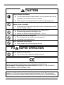
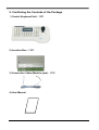
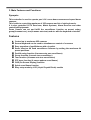
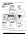
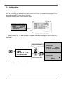
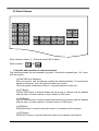
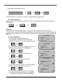
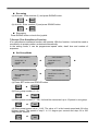
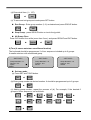
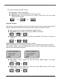
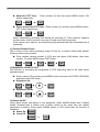
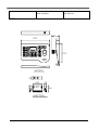
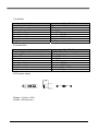
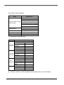
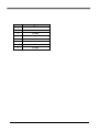
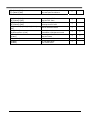
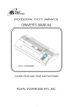
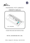
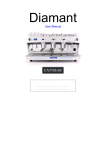
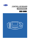
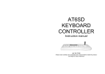
CONTROL KEYBOARD USER MANUAL DCK-255 DCK-255 CCTV CONTROL KEYBOARD PRESET ALL RUN HOLD 1 2 3 4 5 6 SWING Z/I Z/0 F/F F/N MENU STAUS ALAR 7 8 9 C/P L/P AUX1 CLR 0 ENT CAM MON QUAD AUX2 ALARM ON OFF GROUP TOUR SET Table of Content 1. Advisement 4 2. Confirming the Contents of the Package 6 3. Main Features and Functions 7 4. Appearance and Function Keys 5. 1) 2) 3) 4) 5) 6) 7) 8) 9) 10) 11) 12 13) Functions and Operations Initial Setup of keyboard Camera Selection Operating Joystick and Camera in manual Camera Setup (Enter into OSD menu) Preset Swing Group (Tour Surveillance Function) Tour (Auto-Tour Surveillance Function) Spiral Function PTZ Trace (Pattern Surveillance Function) Camera Remote Reset Brightness Control of LCD Alarm On/Off 6. Maintenance 7. Connections 8. 1) 2) 3) 4) 5) 6) General Specifications Controller Junction Box DC Power Supply Camera Control Interface Table of Junction Box Pin Table of Pin between Controller and Junction Box 9. Quick Reference 3 1. Advisement WARNING Always have the unit installed by the store it was purchased from. z Improper connections and/or installation could result in electrical shock, fire or other serious injury or damage. Do not place the unit on an unstable surface. z Always checks the strength and stability of the installation location. z A falling unit will result in damage and could cause serious injury. Never disassemble or attempt to repair or modify the unit. z Disassemble by untrained personnel could result in serious electrical shock, fire and/or malfunction. Never use in locations where combustible materials are used. z The unit should never be used where combustible materials, such as gases, are being used. z Fire, explosion or other serious accidents could occur Never touch electrical connections with wet hands. z Touching electrical connections with wet hands could result in serious electrical shock. Never expose the unit to water. z If the unit becomes wet, turn off the power and unplug it immediately. z Stop using the unit if it becomes wet and contact your nearest supplier or manufacturer representative. Never use the unit if there is an abnormality. z Turn off the power and unplug the unit immediately if there is any type of z abnormality, such as a strange smell or smoke. Continuing to use a unit that is not operation properly could result in serious injury or damage to the unit. Always use the designated power supply. z Failure to use the proper power supply could result in fire, electrical shock, serious injury and/or damage. z Always uses the designated power supply. Always handle the connecting cords properly. z Never damage or modify the connecting cords. z Never pull on the connecting cord, expose them to extreme heat and/or place heavy objects on top of them. z Failure to follow these warnings could result in fire, electrical shock or other damage or injury. 4 CAUTION Always use the unit indoors. z The unit should never be used outdoors, or in any place where it will be exposed to rain or other extremes of moisture. z Direct exposure to water will result in rust and will damage the unit. Never use in environments that have heavy concentrations of dust, smoke, steam or humidity. z Environments such as these could result in fire, electrical shock or other serious damage or injury. Never place the unit in extremes of high or low temperatures. z Extreme temperatures will damage the unit. z Always use within an operating range of 0℃ to 40℃. Never place the unit near the magnetic. z The unit should never be placed near by magnetic. z It is reason for the malfunctions. Never expose the unit to impact. z Strong impact may seriously damage the unit. FOR PROPER OPERATION Never install the unit yourself. z The unit should be installed by trained personnel. This product has been designed and manufactured in accordance with the harmonized European standards, following the provisions of the below stated directives. Electromagnetic Compatibility Directive 89/336/EEC(EN61000-3-2:1995, EN61000-33:1995, EN50081-1:1992, EN50082-1:1997) This devise complies with part 15 of the fcc rules operation is subject to the following two conditions: (1) This device may not cause harmful interference and (2) This device must accept any interference received including interference that may cause undesired operation 5 2. Confirming the Contents of the Package 1) Control Keyboard Unit : 1 PC 2) Junction Box : 1 PC. 3) Connection Cable (Modular jack) : 1 PC 4) User Manual 6 3. Main Features and Functions Synopsis This controller is used to operate pan / tilt / zoom dome cameras and speed dome cameras. This is able to control the maximum of 255 cameras and lot of sub-keyboards. It is also controlled CCTV Receivers, Matrix Systems, Alarm Receiver and other controlled Equipments. Dome Camera can set and fulfill the surveillance function as preset, swing, group(it means tour), tour(it means auto-tour) and etc with the keyboard controller. Features Control up to maximum 255 cameras Several keyboard can be used to simultaneous control of a camera Easy operation of pan/tilt/zoom with a joystick. Same effect as 64 fixed surveillance cameras by setting the maximum 64 preset positions. Pan/tilt swing function (it means auto pan surveillance) Group function (it means tour surveillance) Tour function (it means auto-tour surveillance) PTZ trace function (it means pattern surveillance) OSD (On Screen Display) function Spiral surveillance function Easy setup mode by LCD (Liquid Crystal Diode) module 7 4. Keyboard Functional Keys 1) Controller functional Keys 2) Connecting the Junction Box 8 The keyboard is wired directly to a maximum of 255 receivers, dome cameras. You can communicate using D-MAX Protocol. It has an exclusive RS-485/RS-422 chip set into the keyboard to communicate. There is power supply terminal to use keyboard in rear junction box. The power supply is for 12 VDC included package. 485+ 485- NC NC 485+ 485- N C NC 422 422 422 OUT+ OUT- IN+ IN- 422 CAMERA CONTROL 1 422 422 422 OUT+ OUT- IN+ IN- CAMERA CONTROL 2 RX NC GND GND 422 485+ 485- N C RX RTS RTS 접지 GND 422 422 422 422 OUT+ OUT- IN+ IN- SUB KEYBOARD INPUT/OUTPUT TERMINAL OF DATA JUNCTION BOX Camera controls 1 The keyboard can be installed, using either RS-485 or RS-422 communication. When you communicate with RS-485, convert the 422/485 switch on the left side and when you communicate withRS-422, convert the 422/485-switch on the left side. Connect end of RS485+ data cable from camera to terminal of data(+) and end of RS485- data cable from camera to terminal of data(-) on the junction box. It is input and output terminals. Camera controls 2 Same as camera control 1. Sub keyboard Sub keyboard must be used only with sub keyboard and linked with same line. It can be used up to 8-sub keyboard with one of main keyboard. For communicating with RS-485, the 422/485 switch on the right side of junction box must be converted to 485. For communicating with RS-422, the 422/485 switch on the right side of junction box must be converted to 422. 9 Communication to the keyboards is RS-485. Maximum cable distance for RS-485 communication over 24-gauge wire is 1.2 Km (App. 4000 feet). We recommend using shielded twisted pairs cable that meets or exceeds the basic requirements for EIA RS-485 applications. Junction Box’s input and output terminal Plug the power supply, 12 VDC into suitable outlet on the rear of the junction box. It is also supplied power to keyboard. It is included into keyboard package. Use the data cable that is supplied with keyboard package. Plug one end of cable into the RJ-45 connector on the rear of the keyboard and other end into the RJ-45 connector on the rear of the data junction box. “Exteriorly pull up” is? Don’t put pull up resistance to collector of transistor and make ‘The line driver’ pull up, then it can run function normally. Ascertain The check voltage of GND and RTS should be over 5V. Caution Sub keyboard can run function only in general control. Under the situation that alarm is on in main keyboard, you can hear alarm sound when sensor actuated. Data cable using for control of camera only connected to main junction box, can make sub keyboard function. 10 5. Functions and Operations Main keyboard is setup for regular products. So sub keyboard needs to be set. (If you want to use sub keyboard, please ask to the supplier of it.) 1) Initial Setup of Keyboard Plug in the power supply and then the menu screen appears on LCD with a sound as below. Please Wait! <CCTV Transmitter> Camera : 001 Input? [MAIN] Version X.X 11 SET SUB KEYBOARD DC9V CONTR CONTR SUB OL. 1 OL. 2 KEY. 485+ 485- SET MAIN KEYBOARD DC9V CONTR CONTR SUB OL. 1 OL. 2 KEY. 485+ Up to 128 cameras 485+ 485+ 485- 485- 485- 485+ 485485+ 485- Up to 128 receivers 485+ 485- 485+ 485- This keyboard can be converted to Matrix main (or, sub) keyboard, CCTV Transmitter main (or, sub) keyboard. For matrix, please refer to the matrix manual. (The default is CCTV Transmitter main and one of sub) 12 3-1. Initial setting Select Sub-keyboard. Plug in one end of RJ-45 cable from data junction box to rear of keyboard terminal port at the same time press SET button during 3 Seconds. It appears message with a sound as below figure. <User Keyboard Set〉 1.Matrix 2.TX Key 3.Receiver Select 4.Alarm Set Select number (2) TX Key and then it appears as below message in the LCD on the keyboard. <CCTV Transmitter> If set CCTV TX Main, Camera:001 Input? ■ 2 < CCTV Transmitter > 0 0=MAIN SUB KEY NO (1 -> 8) Press Numeric Key 1 [MAIN] (If there is no sub, please i nput 1.) ~ 8 If set CCTV TX SUB, It can be programmed up to 8-sub keyboard. 13 <CCTV Transmitter> Camera:001 Input? [SUB1] ■ 2) Select Camera ALL RUN HOLD 1 2 3 4 5 6 7 8 9 C/P L/P CLR 0 ENT CAM MON Z/I Z/O F/F F/N AUX1 AUX2 ALARM VIEW ON OFF MENU STAT. Enter camera number (1 ~ 255) and press CAM to select. Select camera : 1~ ¨ CAM 3) Joystick and operation of camera in manual The camera selected can be operated by joystick. It should be operated pan / tilt / zoom with the joystick. (a) Pan/Tilt/Zoom Operating Move the joystick until the camera reached the desired position. To increase the speed of movement, move the joystick further from center. Twist the joystick clockwise to zoom in, counterclockwise to zoom out. (b) F/F Button FOCUS FAR button in manual makes the focus lens of camera until the desired effect is seen. It is also used as a “enter” button in OSD menu. (c) F/N Button FOCUS NEAR button in manual makes the focus lens of camera until the desired effect is seen. It is also used as a “escape” button in OSD menu. (d) Z/I Button ZOOM IN button in manual makes the zoom in of camera until the desired. (e) Z/O Button ZOOM OUT button in manual makes the zoom out of camera until desired. 14 4) Camera Setup (Enter into OSD Menu) OSD (On Screen Display) Control The Keyboard can be controlled speed dome camera, ptz dome camera with OSD menu. Enter into OSD Menu ALL RUN HOLD 1 2 3 4 5 P-SET SWING Z/I Z/O F/F F/N MENU STATUS 6 7 8 9 CLR 0 ENT GROUP TOUR SET KEYBOARD FIGURE 1 + MENU (1) Press number 1 and MENU button respectively to enter OSD menu on the screen. NOTE : The distance time between push 1 and MENU button is about 2 ~ 3 sec. The shift of cursor in OSD Menu (a) Cursor to left – move the joystick left (b) Cursor to right – move the joystick right (c) Cursor to up – move the joystick up (d) Cursor to down – move the joystick down (e) Enter – move the joystick left or right on the parameter (f) ESC – move the joystick left or right according to message on parameter Save and quit in OSD 1 + MENU (a) Press again number 1 and MENU button (b) After set or change parameters, press again number 1 and MENU button respectively to escape from OSD menu with saving or without saving. 15 NOTE : The distance time between push 1 and MENU button is about 2 ~ 3 sec. 5) Presets The keyboard can be programmed up to 64 preset positions for each camera. The memorized preset position is available to replace new preset position and it can be changed. ALL RUN HOLD 1 2 3 4 5 P-SET SWING Z/I Z/O F/F F/N MENU STATUS 6 7 8 9 CLR 0 ENT GROUP TOUR SET KEYBOARD FIGURE Programming the preset mode SET ¨ 1 ~ 64 ¨ P-SET To program, position camera, enter desired preset number (1~64), and press P-SET button then it should be set preset. The function enables program together with pan, tilt, zoom, focus by the joystick. Movement to a preset position Enter memorized preset position number with the keypad and press P-SET key then the camera move to the programmed position as you desired. In error, it will be buzzor sound in two times. 1 ~ 64 ¨ P-SET Delete programmed preset Press the CLR button for a while. (more than 3 sec) 1 ~ 64 ¨ P-SET ¨ ENT 16 Ex) delete the preset number 5. CLR (press more than 3 ¨ ¨ 5 P-SET ¨ ENT Press CLR button, number (5), P-SET, and ENT button respectively. Delete all preset Press CLR button for a while (more than 3 sec), and press PST button and press finally ENT button. ¨ CLR P-SET ¨ ENT 6) Swing The keyboard can be programmed 1 of swing for pan swing and tilt swing in each. It should be run auto pan surveillance between memorized two preset position as desired and it should be also auto tilt surveillance between memorized two preset position as desired. - SET SWING – Set swing mode (a) Press SET and SWING button. (c) It appears message on the LCD as left. (d) Enter number 1 or 2 to select pan/tilt swing. 1 or 2 ¨ - SET SWING – ENT (e) If you select pan swing. It appears next view. (f) Enter preset number for SW Start No. 1 ~ 64 ¨ ENT ¨ ENT ¨ ¨ SW End No? Camera : 001 Input ? SW Time? 1 – 127 sec Camera : 001 Input ? ENT (i) The dwell time can be set 1 to 127 seconds. (j) Enter swing speed value on the LCD. 1 ~ 64 - SET SWING – (h) Enter swing dwell time on the LCD. 1 SW Start No? Camera : 001 ? Input - SET SWING – (g) Enter preset number for SW End No. 1 ~ 64 SW Mode : 1=Pan 2=Tilt Camera : 001 ENT (k) The swing speed can be set 1 to 64 steps. (l) Finally, after enter speed value, it should be escaped the swing set mode automatically. 17 - SET SWING – SW Speed? 1 – 64 Camera : 001 Input ? Run swing (a) Auto-pan : Enter number (1) and press SWING button. 1 ¨ SWIN (b) Auto-tilt : Enter number (2) and press SWING button. 2 ¨ SWIN Stop swing Press SWING button or touch the joystick. 7) Groups (Tour Surveillance Function) It is a sequence surveillance function with presets. With the function, it should be made a surveillance to preset position as desired automatically. In the setting mode, it can be programmed speed value, dwell time and number of sequence. Set Group Mode - SET GROUP – - SET GROUP – ¨ Group No? 1-6 Camera : 001 Input? Preset No? 1-64 Camera : Group-1 ¨ - SET GROUP – - SET GROUP – Move Speed? 1-64 Camera : Group-1 001 ¨ 001 Dwell Time? 1-127 sec Camera : 001 Group-1 (a) Press SET button and GROUP button. SET ¨ GROUP (b) Enter group number (1 ~ 6). 1~6 ¨ ENT (c) Enter preset number (1 ~ 64). It should be memorized up to 12 preset in one group. 1~64 ¨ ENT (d) Enter preset speed value (1~64). The value of 1 is the lowest speed and 64 is the highest speed. The speed of step 1 is 0.1 degree per second and step 64 is 360 degrees per second. 1~64 ¨ ENT 18 (d) Enter dwell time (1 ~ 127). ¨ 1~127 ENT (e) To save and exit group set mode press SET button. Run Group : Enter group number (1~6) as desired and press GROUP button. ¨ 1~127 ENT Stop Group : press GROUP button or touch the joystick. All Group Clear Press CLR button for a while (more than 3 sec.) and press GROUP and ENT button. ¨ CLR ¨ GROUP ENT 8) Tour (it means auto-tour surveillance function) The keyboard should be programmed 1 of tour sequence included up to 6 groups. It means auto-tour with memorized group. - SET TOUR – - SET TOUR – Group Number? 1-6 ¨Camera : 001 Input? [MAIN] - SET TOUR – Group Number? 1-6 ¨ Camera : 001 Save-1 Group Number? 1-6 Camera : 001 Save-6 Set tour mode (a) Press SET and TOUR button. SET ¨ TOUR (b) Enter group number as desired number. It should be programmed up to 6 groups. 1~6 ¨ ENT (c) Adding group number, repeat the process of (b). For example, if the desired 6 groups in a tour sequence, set as follows. 1 ¨ ENT 3 ¨ ENT 6 ¨ ¨ ¨ 2 4 ¨ ENT ¨ ENT ENT 19 ¨ ¨ 3 5 ¨ ¨ ENT ¨ ENT ¨ (d) To finish setting, press SET button. Run Tour : Press TOUR button. Stop Tour : Press TOUR button or touch the joystick. Clear all tour : Press CLR button for a while. (more than 3 sec) and press TOUR and ENT button. ¨ CLR ¨ TOUR ENT 9) Spiral Function This function will be supported only at speed dome camera, the fixed pan speed and tilt speed is operated at the same time that can make a spiral surveillance function. Enter number (7) and then press MENU, ON/OFF button. Run Spiral : Enter number (7) then press MENU, ON button. 7 ¨ MENU ¨ ON Stop Spiral : Enter number (7) and then press MENU, OFF button or touch the joystick. 7 ¨ MENU ¨ OFF 10) PYZ Trace (It means pattern surveillance function) The keyboard makes sure of meeting for this function in superior speed dome camera. The function makes to memorize pan/tilt/zoom movement for 120seconds and play back that trace to memorized movement. - CCTV Transmitter – Trace ON/OFF? Camera : 001 Input? [MAIN] - CCTV Transmitter – Trace Set/Delete? Camera : 001 Input? [MAIN] 8 9 Run Trace : Enter number (8) and then press MENU button, ON button respectively. 8 ¨ MENU ¨ ON Stop Trace : Enter number (8) and then press MENU button, OFF button respectively or touch the joystick. 8 ¨ MENU ¨ OFF 20 Memorize PTZ Trace : button respectively. 9 ¨ MENU ¨ Enter number (9) and then press MENU button, ON ON Delete memorized PTZ Trace : Enter number (9) and then press MENU button, OFF button respectively. 9 ¨ MENU ¨ OFF When manipulating according this setting the message of “Trace memory” appears on the screen. At the moment, move pan, tilt and zoom with the joystick. If the memory time expires, the memorizing stop automatically and memorized ptz is registered. 11) Camera Remote Reset This is same as the action switching power off and on (it means reboot) and doesn’t influence preset memory data. Enter desired camera number (1~255) and then press CAM button, then enter number 10, press MENU button, ENT button. 1~255 ¨ CAM ¨ 10 ¨ MENU ¨ ENT 12) Brightness control of LCD This function is controlling the brightness of LCD and being able to be used where desired location. Enter number (20) and then press MENU button and move JOYSTICK UP/DOWN and then press CLR button. Brightness Up 20 ¨ MENU ¨ up ¨ CLR ¨ CLR Brightness Down 20 ¨ MENU ¨ dow 13) Alarm On/Off Using alarm sensor with preset or any equipment, press ALARM button and if related sensor actuated then it makes sure of alarm sound at the same time the related equipment is working. Press again ALARM button or CLR button then the function is cancelled. Alarm On : ALARM Alarm Off : ALARM or CLR 21 6. Maintenance and Mending If the surface of the keyboard becomes dirty, turn off the power and wipe the surface with a soft dry cloth. CAUTION z Never use strong cleaners, such as alcohol, benzene or paint thinner to clean the surface of the keyboard. They will damage the surface and could cause fire or other accidents. z Cleaning and inspecting of the internal components should only be performed by authorized technicians. Contact your nearest representative for details. FOR PROPER OPERATION Never install the unit yourself. z The unit should be installed by trained personnel. Trouble Shooting It does not power on. Check Point References Does the RJ-45 data cable plug in between junction box and keyboard? Please plug in suitable outlet between keyboard and junction box. Does the power sources supply now? Please make sure of the plug power supply into power consent. It does not work pan/tilt movement. Did you make sure of input camera number as desired? After press CLR button and then input camera number exactly. It does not work in a subkeyboard. Did you set address of subkeyboard in initial setting? Please check the address of subkeyboard again. Did you plug into data cable in tight? Please check plug in data cable and polarity of data cable. It does not work preset movement. Did you set preset position in preset setting mode? 22 Please make sure of setting preset position as desired. It does not work alarm on. Did you make sure of turn off all of alarm channels? If alarm channel is off, it does not work alarm on. 7. Dimensions 83. 337. 31. PRESET ALL RUN HOLD 1 2 3 4 5 6 SWING Z/I Z/0 F/F F/N MENU STAUS GROUP TOUR SET ALAR M 7 8 9 C/P L/P AUX1 AUX2 ALARM CLR 0 ENT CAM MON QUAD ON OFF 179. D-max 10 KEYBOA 29 108, 92. 29 64 JUNCTION 23 1) Controller Item Input/output terminal Interface between junction box Working temperature Storage temperature Working humidity Storage humidity Dimension Weight Specification Modular Jack TTL 0 ~ 40 °C -5 ~ 55°C Less than 75%RH Less than 95%RH 338(L) x 180(W) x 84(H) 1.2 Kg 2) Junction Box Item Power supply Input/output terminal Control I/F between camera and keyboard Working temperature Storage temperature Working humidity Storage humidity Dimension Weight 3) DC power supply Voltage : 9 Vdc(+/- 20%) Current : 500 mA (min) 24 Specification 9 VDC, 500 mA power supply Modular Jack RS-485/RS-422 0 ~ 40 °C -5 ~ 55°C Less than 75%RH Less than 95%RH 109(L) x 66(W) x 27(H) Approx. 0.3 Kg 4) Camera control interface ITEM Specification Asynchronous Serial Interface 1 Start bit Synchronization system 8 Data bit & DATA length No parity 1 Stop bit 11 Byte command Signal polarity Mark logic "1" Space logic "0" Transmit system Half duplex Communication speed 9600 bps Hardware 3 Cable (twist pair + 접지) 5) Constitution of junction box Item Camera control 1 In/Out Camera ↔Junction box ↔Sub key RS-485+ Camera data + RS-485- Camera data - RS-422+ RS-422GND RS-485+ Camera data + RS-485- Camera data - Camera RS-422 in+ control 2 RS-422 inGND Sub keyboard RS-485+ RS-485+ RS-485- RS-485- RS-422 in+ RS-422 in+ RS-422 in- RS-422 in- GND SK RTS RX RTS GND z Camera control 1 and 2 compose each separate driver circuit internally. 25 Pin no. Controller ↔ Junction box 1 RX-TXD 2 B+9V 3 RX-RXD 4 RX-RTS 5 GND 6 SK-TXD 7 SK-RTS 8 SK-RXD 26 9. Quick References OPERATION 〔 Keyboard 1-255〕+〔CAM〕 Power Supply ON +〔SET〕 FUNCTION Function Input Main Sub Select Camera ◎ ◎ Initiative Controller Setting ◎ ◎ ◎ ◎ [SET] Start Set Mode [SET]+[J.S Stop]+[Keypad 1~64]+[PST] [Preset No]+[PST] [CLR+3sec]+[Keypad 1~64]+[PST]+[ENT] [CLR+3sec]+[PST]+[ENT] Input and Set the Preset Position Move to Preset Position Deletion of Individual Preset Position Deletion of Whole Preset Positions [SET]+[SWING] [1/2]+[ENT] [Keypad1~64]+[ENT]+[Keypad 1~64]+ [ENT] [Keypad 1~127]+[ENT] [Keypad 1~64]+[ENT] [1/2]+[SWING] [SWING]/Joystick Start Set Swing Mode Selection of Pan or Tilt Swing Setting up of 2 Preset Positions Setting up of Swing Speed Setting up of Dwell Time Executing Pan or Tilt Swing Stop Swing ◎ ◎ [SET]+[GROUP] [Keypad 1~6]+[ENT] [Keypad 1~64]+[ENT] [Keypad 1~64]+[ENT] [Keypad 1~127]+[ENT] [SET] [Keypad 1~6]+[GROUP] [GROUP]/Joystick Start Set Group Mode Assigning the Group Number Selection of Preset Position Setting up the Move Speed of Group Setting up of Dwell Time Completion of Group Setting Executing the Group Surveillance Stop the Group Surveillance ◎ ◎ [SET]+[TOUR] [Keypad 1~6]+[ENT]←repeat [SET] [TOUR] [TOUR]/Joystick Start Set Tour Mode Setting up Tour Completion of Tour Setting Executing the Tour Surveillance Stop the Tour Surveillance ◎ ◎ ◎ ◎ [MENU] [1]+[MENU] [F/F]/Joystick [F/N] Start Menu Mode Entering OSD Menu OSD Menu Enter OSD Menu Escape [2]+[MENU]+[ON/OFF] Motion Detect ON/OFF ◎ [3]+[MENU]+[ON/OFF] Detection Zone Display ON/OFF ◎ [4]+[MENU] Joystick [Z/I,Z/O]/[F/F,F/N] Detection Zone Size Setting Mode Enlarging the Size (up/down, light/left) Reducing the Size (up/down, light/left) ◎ [5]+[MENU] [Keypad 1~10]+[ENT] Motion Sensitivity Adjusting Mode Highest Sensitivity →10 Lowest Sensitivity →1 ◎ [6]+[MENU] [keypad 1~64]+[ENT] Motion Preset Set up Mode Motion Preset Set up ◎ 27 [7]+[MENU]+[ON] [7]+[MENU]+[OFF] Executing the Spiral Surveillance Stop the Spiral Surveillance ◎ [8]+[MENU]+[ON] [8]+[MENU]+[OFF] Executing the PTZ Trace Stop the PTZ Trace ◎ [9]+[MENU]+[ON] [9]+[MENU]+[OFF] PTZ Trace Memorizing Deleting the PTZ Trace ◎ Reset of Selected Camera ◎ [Keypad1~255]+[CAM]+[10]+[MENU]+ [ENT] [20]+[MENU] Joystick up/down +[CLR] LCD Brightness Control Cancellation of Brightness Control ◎ ◎ [STAUS] [STAUS] Executing the Freeze Stop the Freeze ◎ ◎ [1]+[STATUS] Confirmation of MD set Camera ◎ [ALARM] [ALARM] Go Into Alert Mode Out of Alert Mode ◎ 28 DISTRIBUTED BY