1
PROFESSIONAL
PROFESSIONAL
ROUTER TABLE
MESA PROFESIONAL
DE FRESADO
OWNER'S MANUAL
Models:
171.264630
171.264640
(without Floor Stand)
(with Floor Stand)
MANUAL DEL PROPIETARIO
Modelos
171.264630
171.264640
(sin base)
(con base)
WARNING:
Before
operating product,
read this manual and
follow all its Safety and
Operating Instructions.
ADVERTENCIA:
Antes de utilizar este
producto, lea este
manual y siga todas
las instrucciones de
uso y seguridad.
Sears, Roebuck and Co., Hoffman
171.264630
and 171.264640
04101 Printed in U.S.A.
Estates IL 60179 USA
Hecho en los Estados Unidos
General
Safety Instructions
Additional
Safety Instructions
Introduction
Optional
for Power Tools ...............................................
for Router Tables ........................................
.....................................................................................................
Router Table Accessories
Unpacking
and Checking
Contents
Installation
6
7
..............................................................
8
8
.......................................................................................................
13
.....................................................................................................
24
Switch Instructions
Operation
4
...............................................................
Parts List .........................................................................................................
Assembly
3
.......................................................................................
27
.......................................................................................................
34
Espa_ol ..........................................................................................................
42
2
SAFETY GUIDELINES
This manual contains
information that is important for
you to know and understand.
This information relates to
protecting YOUR SAFETY and
PREVENTING EQUIPMENT
PROBLEMS. To help you
recognize this information, we
use the symbols to the right.
Please read the manual and pay
attention to these sections.
i -4LWARNINGI
- DEFINITIONS
I, DANGER I
I_C*UT'ON]
URGENT SAFETY INFORMATION -
INFORMATION FOR PREVENTING
A HAZARD
DAMAGE TO EQUIPMENT
THAT
WILL CAUSE
SERIOUS INJURY OR LOSS OF LIFE
IAWARNING
I
I
NOTE
I
IMPORTANT SAFETY INFORMATION -
INFORMATION THAT YOU SHOULD
A HAZARD
PAY SPECIAL A'I-FENTION TO
THAT
MIGHT
CAUSE
SERIOUS INJURY OH LOSS OF LIFE
Failure to heed all safety and operating instructions and warnings regarding use of this
product can result in serious bodily injury.
1.
2.
3.
4.
5.
6.
7.
Know your power tool
Read the owner's manual carefully. Learn its
application and limitations as well as the specific
potential hazards peculiar to this tool.
Ground all tools (unless double insulated)
If tool is equipped with an approved threeconductor cord and a three-prong grounding
type plug, it should be plugged into a three hole
electrical receptacle. If adapter is used to accommodate a two-hole receptacle, the
adapter wire must be attached to a known
ground (usually the screw securing receptacle
cover plate). Never remove third prong.
Never connect green ground wire to a terminal.
Keep guards in place
Maintain guards in working order, and in proper
adjustment and alignment.
Remove adjusting keys and wrenches
Form a habit of checking to see that keys and
adjusting wrenches are removed from tool before
turning it ON.
Keep work area clean
Cluttered areas and benches invite accidents.
Floor must not be slippery due to wax or sawdust.
Avoid dangerous environment
Do not use power tools in damp or wet locations or
expose them to rain. Keep work area well lighted.
Provide adequate surrounding work space.
Keep children away
All visitors should be kept a safe distance from
work area.
8.
9.
Make workshop child-proof
Use padlocks, master switches, or remove
starter keys.
Do not force tools
They will do the job better and safer at the rate
for which they were designed.
10. Use the right tool
Do not force tool or attachment to do a job it was
not designed to perform.
11. Wear correct apparel
Do not wear loose clothing, gloves, neckties
or jewelry (rings, wristwatches) that may get
caught in moving parts. Non-slip footwear is
recommended. Wear protective hair covering
to contain long hair. Roll long sleeves above
the elbow.
12. Use safety goggles (Head Protection)
Wear safety goggles (must comply with ANSI
Standard Z87.1) at all times. Also, use face or
dust mask, if cutting operation is dusty, and
ear protectors (plugs or muffs) during extended
periods of operation.
13. Secure work
Use clamps or a vise to hold work when
practical. It's safer than using your hands,
and both hands are free to operate tool.
14. Do not overreach
Keep proper footing and balance at all times.
15. Maintain tools with care
Keep tools sharp and clean for best and safest
performance. Follow instructions for lubricating
and changing accessories.
3
21. Direction of feed
Feed work into a blade or cutter AGAINST the
direction of rotation of the blade or cutter only.
22. Never leave tool running unattended
Turn power OFF, DO NOT leave tool until it
comes to a complete stop.
23. Keep hands away from cutting area
24. Store idle tools
When not in use, tools should be stored in dry,
high or locked-up place - out of reach of children.
25. Do not abuse cord
16. Disconnect tools before servicing
Before servicing, when changing accessories
such as blades, bits, cutters, etc.
17. Avoid accidental starting
Make sure switch is in OFF position before
plugging in.
18. Use recommended accessories
Consult the owner's manual for recommended
accessories and follow the instructions. The use
of improper accessories may cause hazards.
19 Never stand on tool
Serious injurycould occur if the tool is tipped or if
the cutting tool is accidentally contacted. DO NOT
store materials above or near the tool making it
necessary to stand on the tool to reach them.
20. Check damaged parts
Before further use of the tool, any guard or
other part that is damaged should be carefully
checked to ensure that it witl operate properly
and perform its intended function. Check for
alignment of moving parts, binding of moving
parts, breakage of parts, mounting, and any
other conditions that may affect its operation. A
guard or any other part that is damaged should
be properly repaired or replaced.
Keep cord away from heat, oil and sharp edges.
26. Outdoor extension cords
When tool is used outdoors, use only extension
cords suitable for use outdoors and so marked.
1.
Always wear eye protection that complies with
ANSI Standard Z87.1.
9.
2.
Noise levels vary widely with location. To avoid
possible hearing damage, wear ear plugs or
ear muffs when using your router table for long
periods of time.
For dusty operations, wear a dust mask along
with safety goggles.
Follow the instructions in your router owner's
manual.
3.
4.
27. Never use in an explosive atmosphere
Normal sparking of the motor could ignite fumes,
flammable liquids, or combustible items.
28. Drugs, alcohol, medication
Do NOT operate tool while under the influence
of drugs, alcohol, or any medication.
Read and Understand this instruction book completely BEFORE using this product.
10.
11.
12.
5.
[_,WARNINGJ
6.
during use, can cause fasteners to become loose.
Before use and periodically during use, check all
fasteners to make sure that all are tight and
secure.
Do not use this product until all assembly and
installation steps have been completed. Make
sure you have read and understood all safety
and operational instructions in this manual and
the router owner's manual.
7.
8.
Vibrations, caused by the router
13.
14.
15.
Make sure that the router bit is properly
positioned and clamped in the router before
making any cuts.
Do not use the router table as a workbench or
work surface. Doing so may damage it, causing it
to be unsafe to use. A workbench should be
used for this purpose.
16.
4
This product is designed for cutting flat
workpieces. Do not cut or attempt to cut
workpieces that are not flat.
This product is designed for cutting wood
workpieces only. Do not use to cut metal
or other non-wood materials.
The use of auxiliary in-feed and out-feed
supports is strongly recommended when routing
long workpieces. Otherwise those workpieces
can cause the router table to tip over.
Keep hands clear of the router bits and
working area.
Make and use a push stick to move small
workpieces across the cutting area or purchase
9-25468 Router Table Guide Master.
Clean the router after use. The use of a wet/dry
vac or vacuum equipment is recommended.
Always make sure that work surface of the router
table is clean and free from dust, chips, and
foreign particles that can interfere with the cut
you are going to make. The use of a wet/dry
vac or vacuum equipment is recommended.
Check the function of the guard before each
use. Remove all dust, chips, and any other
foreign particles that can affect its function.
[^
]
17 [ABLWARNINGj
Never put your fingers under
the guard when the router is plugged into an
electrical outlet or when the router bit is rotating.
18. Always use the fence to guide the workpiece.
19. Always feed the workpiece AGAINST the
rotation of the cutter or router bit.
20. Router bits are extremely sharp; be extra careful
when handling and using them.
21. Make sure that the router bits being used are
sharp or have been properly resharpened. This
will permit fast, efficient, and SAFE routing.
22. Some routers, when positioned in an upside down
position (such as on a router table), will drop or
fall out of the router base when the base clamp
is loosened to adjust height or depth of cut.
Therefore, it is extremely important to support
the router from below when making these
adjustments or whenever the base clamp
is loosened.
23. Always look under the router table at the router
switch when turning the router ON or OFF. DO
NOT touch anything but the switch when doing
this. NEVER reach under the router table for any
reason when the router is running, except to turn
it OFF.
24. I_,IIALWARNING I Before making any cut, make
sure the router is turned OFF, the router bit is
not rotating, and the power cord is unplugged
from the electrical outlet. Then, make absolutely
sure that the guard clears the router bit and the
workpiece. A trial pass, with the router turned
OFF and the router bit not turning, is strongly
recommended.
IA
25. JA_WARNING]
I
Never leave the router table
unattended while the router is running. Turn the
router OFF before leaving the router table for
any reason.
26. If ANY part is missing, DO NOT attempt to
assemble, install, or use your router table until
the missing parts have been found or replaced
and your router table has been properly and
correctly assembled per this manual.
27. NEVER use the floor stand as a ladder and DO
NOT stand on the router table.
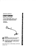
CraftsmanProfessional
RouterTables,Model
171.264630
or Model171.264640,
feature
thefollowing:
• A large, 18" x 27" (486 square inches), precision
die-cast aluminum table top, machined to ensure
true flatness and smoothness.
• The table top has an 11-1/2" x 7-3/4" opening for
mounting routers through the table top.
• An 11-1/2" x 9" router adapter plate will attach to
all Craftsman routers.
• The top is coated with a special anti-friction
coating to ensure ease of use without discoloring
or marring the workpiece.
• Dual cast scales ensure parallel and accurate fence
placements for:
• Specialty woodworking joints
• Edge and face routing
• Panel raising
• Precision 4" high x 27" long extruded aluminum
fence incorporates the following features:
• Fence guides for parallel depth-of-cut
adjustment.
• Adjustability for proper bit clearance
• Dust collection port for 2-1/2" wet/dry
vacuum hose
• Unique offset formed jointing fence for 1/16"
edge jointing
• Precision formed fence also allows you to perform
the following operations:
• Fluting, veining, and molding
• Grooving up to the center of a 6 1/2" work piece
• Dual receptacle ON/OFF switch operates both a
router, vacuum, or light simultaneously:
• Switch has overload protection
• Is UL and CUL listed
• Floor stand, on model 171.264640, places
the router table at a convenient working height
with leveling feet for uneven floors
• ALSO INCLUDED:
• Snap in router bit storage panel for both 1/2"
and 1/4" shank router bits
• Miter gauge for cross grain routing at 90 ° and
60 ° in two directions
9-25188 Router Table Switch
• Switch mounts to the front of all Craftsman
router tables
• Front switch operates two receptacles on the
back of the switch
• Large switch paddle for ease in turning the
switch OFF
• Removable key prevents unauthorized use
when removed from the switch
• Has built-in circuit breaker
9-25468 Craftsman Guide Master Router Table
Push Shoe with Hold Down Stick
• Ideal for handling small work pieces on a
router table
• Aids in accurate measurement and router table
set-up
• Transforms into a miter gauge
• Provides a quick set-up for making 1/2" sliding
dovetail joints
9-26479 Craftsman Professional Large Router
Adapter Plate
• Molded glass-filled polycarbonate plastic
adapter plate mounts most non-Craftsman
routers to the 171.264630 and the
171,264640 Professional Router Tables
• Easy to follow instructions and mounting
templates supplied
• Adapter plate mounts to the router table using
fasteners supplied with router table
• Fasteners for mounting the router to the
adapter plate are not included and must
obtained separately
IMPORTANT NOTE: The drilling and the
countersinking of holes in the adapter plate
are necessary in order to mount the router
to the adapter plate. The screw heads must
be slightly below the top surface of the
adapter plate.
9-26471 Craftsman Feather Board
• Mounts to 171.264630 and the 171.264640
Professional Router Tables only; cannot
be used on any other Craftsman or
non-Craftsman router tables
• Feather boards apply pressure to a workpiece
vertically down towards the table top and
or sideways towards the router table fence providing better control of the work piece
• Adjustable for both small and large
work pieces
• Not to be used on any other type of machinery
or accessory
9-26472 Precision Router Table Fence Assembly
• Mounts to all Craftsman Professional
Router Tables
• Extruded aluminum fence is fully adjustable
measuring 4" high and 27" long
• Fence opening is adjustable for different size
router bits providing greater support
• Exclusive "keyed"jointing feature straightens
workpiece edges for gluing
• Fence assembly has 2-1/2" diameter dust port
for wetJdry vacs with 2-1/2" diameter hoses
• Clear see through guard allows viewing of
the work area
• Incorporates T-slot design for mounting
feather boards
9-26477 Craftsman Enclosure Kit
• Converts the 9-26478 Craftsman Floor Stand
to a convenient storage cabinet
• Includes three panels, door, hinge, magnetic
latch, knob, and mounting hardware
9-26478 Craftsman Floor Stand
• Places router table at optimal working height
• Adjustable non-slip foot pads for leveling table
on uneven floor surfaces
• Two heavy-duty steel shelves for storage
9-26473 Craftsman
Bit Storage Panel
• Easy snap-in installation
• Provides easy and convenient storage for up to
18 router bits
• Holds a mix of both 1/4" and 1/2" shank
router bits
• Will accept all Craftsman bench top router
tables available after 1997
Referto PartsListbelowandon pages9-12
I^
1
• I A_WARNINGI If ANY of the parts is missing,
DO NOT attempt to assemble, install, or use your
router table until the missing parts have been found
or replaced and your router table has been properly
and correctly assembled per this manual.
• For missing parts or technical assistance, call
1-800-624-0488.
• In order to simplify handling and to minimize any
damage that may occur during shipping, your
router table comes unassembled.
• Separate all parts from the packaging materials
and check each part against the illustrations and
the parts lists on pages 9-12, to make sure that all
parts have been included. Do this before discarding
any of the packaging material.
WHENASSEMBLINGROUTERTABLE171.264640,DISREGARDOWNER'SMANUALFURNISHEDWiTHFLOORSTANDMODEL9-26478.
Key No.
Part No.
A
Quantity
Model
Model
9-26463
9-26464
Description
ROUTER
TABLE
ASSEMBLY
1
29LCN-1223
Router Table
1
1
2
3
29LCN-1224
29LCN-997
Fence Support Bracket
Fence Guide (Yellow)
2
2
2
2
4
5
6
29LCN-1174-2
29LCN1229
29LCN-1230
Large Clamping Knob (Yellow)
Router Adapter Plate (Black)
Lower Fence
2
1
2
6
1
2
7
8
9
10
1t
12
29LCN-1232
29LCN-1231-2
29LCN-1233-01
29LCN-t 234
29LCN-1235
29LCN-1236
Upper Fence
Fence Clamping Knob
Dust Collector (Black)
Upper Fence End Cap
Upper Fence End Cap
Lower Fence End Cap
1
4
1
1
1
2
1
4
1
1
1
2
13
14
15
29LCN-1237
29LCN-1238
29LCN-1239
Lower Fence End Cap (Left Side, Black)
Overhead Guard (Clear)
Guard Shaft
2
1
1
2
1
1
16
17
29LCN-1240
29LCN-1241-11
Leg Reinforcement
Table Top Insert w/1"
4
1
4
1
18
19
29LCN-1241-12
29LCN-1241-13
Table Top Insert w/2" Dia. Hole (Yellow)
Table Top Insert w/2-3/4" Dia. Hole (Yellow)
1
1
1
1
20
21
22
23
24
25
29LCN-1242-02
29LCN-1243-02
29LCN-1244
29LCN-1018
29LCN-1176
29LCN-1119
Table Leg (Black)
Table Leg Fascia (Black)
Power Bar Switch Assembly
Switch Key
Protractor Head
Miter Bar
2
1
1
1
1
1
2
1
1
1
1
1
26
27
29LCN-1175-2
29LCN-12-02
Small Clamping Knob (Yellow)
Feather Board
1
1
2
28
29LCN-1247-02
Router Table Leg Insert Cover (Black)
1
1
29
29LCN-1248-02
Router Table Leg Insert Router Bit Storage (Black)
1
1
(Yellow)
(Right Side, Black)
(Left Side, Black)
(Right Side, Black)
Dia. Hole (Yellow)
®
®
Switch Assembly
Fence Assembly
Miter Gauge
Feather Board (#9-26464 only)
o@
G
@
Table Top Inserts
©÷
Quantity
Key No.
Part No.
B
Description
Model
9-26463
Model
9-26464
FASTENERS
30
31
32
29LCN-1016
29A-1113
29A-1172-1
33
34
35
36
37
29LCN-979-1
29LCN-1220-1
29LD-123-2
29LD-841-2
29LD-841-12
38
39
40
29LD-841-14
29A-306-37
29A-306-38
41
42
43
44
45
46
47
48
29A-306-26
29A-310-07
29A-310-24
29A-970-5
29A-970-9
29A-970-13
29A-1257-2
29A-242-14
49
29A-249-1
1/4-20 Weld Nut
#10-32 KEPS Nut
1/4-20 KEPS Nut
#10-16
#10-16
#10-32
#10-32
#10-32
4
21
8
4
65
8
x 1/2" Ig. BT Pan-head Self-Tapping Phillips Screw
1
x 5/8" Ig. BT Countersunk Self-Tapping Phillips Screw 6
ESNA Stop Nut
12
x 5/8" Ig. Countersunk Phil. Head Machine Screw
3
x 1" Ig. Countersunk Phil. Head Machine Screw
4
1
6
12
3
4
5/16-18 x 1-1/4" Ig. Countersunk Phil. Machine Screw
13/64" ID x 9/16" OD x 0.040" thick Washer
9/32" ID x 5/8" OD x 1/16" thick Washer
#10-24
1/4-20
1/4-20
#10-32
#10-32
1/4-20
#10-32
1/4-20
x 7/8" Ig. Carriage Bolt
x 1-3/4" [g. Carriage Bolt
x 1-1/2" Ig. Carriage Bolt
x 1/2" Ig. Truss Head Machine
x 3/4" Ig. Truss Head Machine
x 5/8" Ig. Truss Head Machine
x 3/4" Ig. Countersunk Socket
Hex Machine Screw Nut
1/8" Hex Key (Allen Wrench)
10
Screw
Screw
Screw
Head Screw
3
1
16
3
1
24
1
10
4
9
6
8
6
1
4
14
48
9
6
8
6
1
1
Use the guide below to identify the fasteners included with your Router Table.
Numbers in bold correspond to the key numbers in the parts list on page 10.
@@@@ @@ ©®@@
(31) #10-32
KEPS Nut
(30) 1/4-20 Weld Nut
(32) 1/4-20
KEPS Nut
(38) #10-32
ESNA Nut
(48) 1/4-20 Hex
Machine Screw Nut
@ ©
(39) 13/64" ID x 9/16" OO
x 0.040" thick Washer
(40) 9/32" ID x 5/8" OD x
1/16" thick Washer
(43) 1/4-20 x 1-1/2" Ig. Carriage Bolt
(41) #10-24 x 7/8" Ig. Round Head
Square Neck Bolt
(44) #10-32 x 112" Ig. Truss Head
Phillips Machine Screw
(33) #10-16 x 1/2" Ig. BT
Pan-head Self-Tapping
Phillips Screw
(36) #10-32 x 518° Ig. Countersunk
Phillips Machine Screw
(42) 1/4-20 x 1-3/4" Ig. Carriage Bolt
(48) #10-32 x 3/4" Ig. Truss Head Phillips
Machine Screw
(34) #10-16 x 5/8" Ig. BT
Countersunk Self-Tapping
(46) 1/4-20 x 5/8" Ig Truss Head Phillips
Machine Screw
(36) 5/16-18 x 1-1/4" Ig. Countersunk
Phillips Machine Screw
Phillips Screw
(37) #10-32 x 1" Ig, Countersunk
Machine Screw
(49) 1/8" Hex Key (Allen Wrench)
11
Phillips
(47) #10-32 x 3/4" Ig Countersunk
Head Screw
Socket
Key No.
Part No.
C
FLOOR
50
51
52
53
29LCN-1249-02
29LCN-1250-02
29LCN-1118
29LCN-1117
54
29LCN-1174-2
D
49LCN-75
Quantity
Model
Model
9-26463
9-26464
Description
STAND
ASSEMBLY
Floor Stand Leg (Black)
Floor Stand Shelf (Black)
Leveling Bracket
Leveling Foot (Black)
4
2
4
4
Large Clamping Knob (Yellow)
4
OWNER'S
MANUAL
Craftsman Professional
Router Table Owner's Manual
12
1
1
ASSEMBLING
THE ROUTER TABLE
Figure
TOOLS REQUIRED (not included)
•
Phillips screwdriver
•
Small sized adjustable wrench
•
Tape with adhesive backing
ROUTER
TABLE
LEGS (FIGURES
1A
_"
lc/4_2tgl "10/2;
1A-lC)
1.
Insert eight 1/4-20x1-1/2" long carriage
bolts (43) through the router table top as
shown in Figure 1A.
2.
Place a strip of tape with adhesive backing
over the bolts to temporarily hold them
in place.
3.
Turn the router table top upside down.
4.
Place a leg reinforcement over each set of
carriage bolts as shown in Fig. lB.
5.
6.
Assemble one of the legs to the router table
as shown in the figure.
Assemble a 9/32" ID x 5/80D" x 1/16" thick
washer (40) and a 1/4-20 "KEPS" nut (32)
onto each of the bolts.
7.
Securely tighten the fasteners.
8.
Repeat this procedure for the other side of
the router table as shown in Fig. 1C.
9.
Securely tighten the fasteners.
Figure 1B
9/32 x 5/8 x 1/16" washer
1/4-20 KEPS nut
Leg
reinfor_
10. Turn the router table right side up.
11. Remove the tape holding the bolts in place.
Figure lC
13
_/
ATTACH THE SWITCH
TO THE FASCIA
Figure 2
(FIGURE 2 AND DETAIL 2A)
Refer to the section "OPERATION-OPERATING
THE SWITCH" for instructions on connecting
and using the switch.
head screws
/
Attach the switch to the back of the fascia
using two #10-32 KEPS nuts (31) and two
#10-32 x 3/4" truss head machine screws (45)
(Figure 2).
The toothed washer on the KEPS nut
must face away from the switch assembly
as shown in detail 2A.The hex portion of
the KEPS nut fits into the hex-shaped
recess in the back of the switch case.
2.
#10-32 x 314" truss
Switch
'
_
_
2
"
"
_
i:
-32 KEPS nuts
Detail 2A
TIGHTEN all screws SECURELY.
ATTACH THE FASCIA TO THE ROUTER
TABLE
(FIGURE
3 AND DETAIL
3A)
NOTE: The fascia assembles to the inside of
both the table legs and the router table top,
1
Turn the router table upside down.
2.
Line up the holes on the fascia with the holes
in the table legs and the two slots on the front
of the router table top.
Figure 3
NOTE: in the following two steps, the
toothed washer on the KEPS nut must
face away from the fascia as shown in
Detail 3A.The hex portion of the KEPS nut
fits into the hex shaped recess in the back
of the fascia.
3.
Attach the fascia to the router table top using
two #10-32 x 3/4" long truss head machine
screws (45) and two #10-32 KEPS nuts (31),
as shown in Figure 3.
4,
Attach the fascia to the legs using four
#10-32 x 3/4" long truss head machine screws
(45) and four #10-32 KEPS nuts (31), as
shown in Figure 3.
tea of Detail 3A
_
Detail 3A
_)
5.
_<'_-
#10-32
x 3/4" truss
head screws
TIGHTEN all screws SECURELY.
IMPORTANT:
For Router Table Models 171.264630, which
does NOT include a floor stand, continue with
the next section, on page 15.
For Router Table Models 171.264640, which
does include a floor stand, skip to page 17 and
continue with the section "ASSEMBLING THE
FLOOR STAND".
Q "_- #10-32 KEPS nuts
14
MOUNTING THE ROUTER TABLE TO A
WORK SURFACE OR WORKBENCH
IiI=LWARNINGI
_,
The router table must always be
Figure 4
FIRMLY and SECURELY mounted to a work surface
before use. Failure to do so could cause the router
table to tip over or slide, resulting in property
damage and/or serious personal injury.
TOOLS REQUIRED (not included)
• Phillips screwdriver
• Small sized adjustable wrench
• Electric or hand drill with drill bits (depending on
mounting method used)
• Fasteners (not included):
• Four #14, #16, or #18 x 2" pan head wood
screws (for solid wood work surfaces or
workbenches), or
• Four 5/16" pan head machine screws, washers,
and hex nuts, or
• Clamps.
Figure 5
METHOD 1 (FIGURE 4)
1. Set the router table on a workbench or other
stable and sturdy surface, with the FRONT
(switch side) of the router table facing
toward you.
2.
While holding the router table in the desired
position, mark the location of the four mounting
holes (one in each corner).
3.
Remove the router table from the workbench and
set it aside.
4.
Drill a 1/8" pilot hole (for wood screws) or an
appropriately sized hole (for machine screws) at
the marked locations.
5.
METHOD 2 (FIGURE 5)
1, Set the router table on a workbench or other
Place the router table on the workbench and
stable and sturdy surface, with the FRONT
(switch side) of the router table facing
toward you.
align the mounting holes in the router table legs
with the holes drilled in the work bench.
6.
7.
Secure the router table in place using wood
screws (not provided) or machine screws,
washers, and nuts (not provided). If using
wood screws, applying a little soap to the
screw threads will make it easier to thread
the screws into the pilot holes.
2.
TIGHTEN all screws SECURELY.
15
Secure the router table legs to the workbench
with clamps, making sure to tighten them
SECURELY.
IMPORTANT: Be sure the placement of the
clamps will not interfere with operation of the
router table.
ALTERNATE
1.
2,
METHOD
(FIGURE
6)
Cut a board 18-1/4" wide by 29" long from a
piece of 3/4" thick wood.
Set the router table on the board, with the
FRONT (switch side) of the router table facing
toward you, so that the spacing between the
router table legs and the edges of the board is
equal on all sides.
3.
While holding the router table in the desired
position, mark the location of the four mounting
holes (one in each corner).
4.
Remove the router table from the board and set
it aside.
5.
Drill a 1/8" pilot hole (for wood screws) at the
marked locations.
6.
Place the router table on the board and align the
mounting holes in the router table legs with the
holes drilled in the board.
7,
Figure 6
Secure the router table in place using wood
screws (not provided). Applying a little soap to
the screw threads will make it easier to thread
the screws into the pilot holes.
8.
g.
TIGHTEN all screws SECURELY.
Place the router table on a workbench or other
stable and sturdy surface. Firmly secure the
board to the workbench with screws, clamps,
or other suitable means.
16
ASSEMBLING THE ROUTER TABLE FLOOR STAND
(Model 9-26464)
TOOLS REQUIRED (not included)
• Phillips screwdriver
• Small sized adjustable wrench
ATTACHING THE LEVELING
LEGS (FIGURE 7)
1.
2.
FEET TO THE
Figure 7
Attach a leveling bracket to the inside of each
of the four legs using three #10-32 KEPS (31)
nuts and three #10-32 x 1/2" long truss head
machine screws (44).
NOTE: To simplify assembly and leveling of the
stand, set all four leveling brackets to their fully
retracted position and tighten the fasteners. You
may need to adjust the leveling brackets to your
floor surface later.
Leveling bracket
#10-32 x 1/2 _
machine
screws
Levelir
_,_
/
D
Slide a rubber leveling foot onto the end of each
leveling bracket.
ATTACHING
(FIGURE
foot
J
THE LEGS TO THE SHELVES
8)
NOTE: Both shelves for the floor stand are identical,
as are all four legs.
1,
Place a shelf upside down (flat side down,
mounting flanges facing up) on the floor or
other stable work surface. This will be the
top shelf of the router table floor stand.
2.
Using four #10-32 KEPS nuts (31) and four
#10-32 x 1/2" Ig. truss head machine screws
(44), attach a leg to each corner, as shown in
Figure 8.
SECURELY TIGHTEN all fasteners.
3.
D
# 10-32
KEPS nuts
Attach the lower shelf, with the mounting flange
facing the leveling feet, to the legs using four
#10-32 KEPS nt_ts (31) and four #10-32 x 1/2"
Ig. truss head machine screws (44) on each leg.
SECURELY TIGHTEN all fasteners.
NOTE: It may be easier to align and attach the
lower shelf if you turn the stand on its side.
17
#10-32 x 1/2"
machine
screws
ATFACHING THE ROUTER TABLE TO THE
FLOOR STAND (FIGURE 9)
1, Turn the floor stand upright and set it on its feet.
Figure 9
Clampin_
2. Place the router table on the floor stand and
align the holes in the router table legs with the
square holes in the corners of the top shelf of
the floor stand.
knob and
3. From underneath, slide a 1/4-20 x 1-3/4" carriage
bolt (42) up through the hole in the top floor stand
shelf and router table leg, and secure with a
9/32" ID x 5/8" OD x 1/16" washer (40) and a
large clamping knob. Repeat for the other
three corners.
I III I
_
1
i
1
2. Adjust the leveling brackets as needed to make
sure that the router table surface is level and that
all four leveling feet are in solid contact with the
floor. An assistant may be helpful in keeping the
table level and stable until all four leveling legs
are securely tightened.
18
I
I
I
L
LEVELING THE FLOOR STAND
1. Place the router table and floor stand in the
desired working location. When selecting a
location, be sure to keep in mind sufficient
working space, lighting, and proximity to a
suitable electrical outlet.
__
INSTALLING
TABLE
LEG INSERTS
TABLE LEG INSERTS
(FIGURE
IN THE TABLE LEGS
10)
The router table includes two table leg inserts:
Figure 10
• Router bit storage panel for convenient bit storage
• Cover panel
If the table leg inserts have not been installed on the
router table legs, proceed as follows:
1. Place the table leg insert into the opening in the
table leg so that it is positioned at the very top of
the opening.
2. Press the insert in so that it is completely flush
with the leg.
3. Push the insert down as far as it will go to lock it
in place.
h
ASSEMBLING
wn
THE MITER GAUGE
ASSEMBLE THE MITER GAUGE
(FIGURE 11A AND FIGURE 11B)
Figure 11A
-__ #10-16 x 1/2"
self-tapping
1, Assemble the protractor head to the miter bar, as
shown in Figure 11A, using a #10-16 x 1/2" long
type BT pan-head self-tapping screw (33).
screw
S
2. Tighten the self-tapping screw into the protractor
head so that the screw touches the miter bar but
,
Miter bar
still provides resistance when the protractor head
is rotated.
NOTE: the screw will resist turning when being
threaded into the hole as the screw is cutting
and forming a thread in the protractor head,
ro, aotor
3. Assemble the knob, the 13/64" ID x 9/16" OD x
.040" thick washer (39), and the #10-24 x 7/8"
carriage bolt (41) to the miter bar and protractor
head as shown in Figure 11B.
Figure 11B
Small clamping
knob
4. TIGHTEN the knob SECURELY.
_
_
Washer
Protractor
#10-24 x 7/8"
\,
19
carriage bolt
ASSEMBLING
TOOLS REQUIRED (not included)
• Phillips screwdriver
• Small sized adjustable wrench
FENCE
SUPPORT
BRACKETS
(FIGURE
THE FENCE
Figure 12
1/4-20x 5/8"
--(-_/_
machine screws
J#,o32xl,2
/ .
v//
_
'\
,
Fence
guide
_
'_/
_/,
#10-32 KEPS nuts_
Detail 12A
Attach the fence guides to the fence support
brackets using two #10-32 x 1/2" long truss head
machine screws (44), as shown in Figure 12.
DO NOT tighten the screws at this time.
The orientation of the fence guide in relation
to the fence support bracket must be as
shown.
,
/ ,\
Fence
support
bracket
the hex-shaped openings on the fence guides.
It may be helpful to place the fence guides on
a flat surface and lightly tap the nuts in with
a small hammer.
2*
L-
12)
Insert a #10-32 KEPS (31) nut into each of the
hex-shaped openings in the fence guides, with
the toothed washer facing towards the fence
guide as shown in Detail 12A.
NOTE: The KEPS nuts should "bottom-out" in
1.
-(__
Fence
guide
_
Loosely assemble two 1/4-20 nuts (48) and
1/4-20 x 5/8" long truss head machine screws (46)
to each fence support bracket, as shown in Figure
12. It is not necessary to tighten the fasteners at
this time.
2O
r\
#10-32KEPS
nuts
_
/
DUST COLLECTOR AND GUARD (FIGURE 13)
1. Slide the guard shaft through the holes on the
back of the guard.
2,
3,
4.
Secure the guard to the dust collector with a #1032 KEPS nut (31) and a #10-32 x 3/4" long truss
head machine screw (45), inserting the screw up
through the bottom of the dust collector, as
shown. SECURELY TIGHTEN the screw and nut.
Loosely attach a 1/4-20 KEPS nut
ID x 5/8" OD x 1/16" washer (40),
5/8" Ig. truss head machine screw
the holes on each side of the dust
as shown.
(32), a 9/32"
and a 1/4-20 x
(46) through
collector,
1/4-20 nuts
and 9/32" ID x
5/8" OD washers
Slide the nuts into the T-slot on the back side of
#10-32 x 3/4"
machine screw
the upper fence until the guard/dust collector is
centered on the upper fence.
FENCE
SUPPORT
BRACKETS
Figure 14
AND UPPER
_
Left
upperfence
FENCE END CAPS (FIGURE 14)
1. Slide the nuts on the fence support brackets into
the T-slot on the back of the upper fence, one
bracket at each end of the fence.
DO NOT tighten the fasteners at this time.
fence end cap
IMPORTANT: The end caps are NOT
interchangeable and have identification
marks and alignment tabs.
2.
Secure the end caps to the upper fence rail,
one at each end, with a #10-16 x 5/8" (34) long
countersunk Phillips head self-tapping screw.
NOTE: You will feel resistance when tightening
the self-tapping screws. The use of soap or a
light oil will reduce the resistance. End caps
should be attached squarely and tight against
the fence rail.
__
21
support bracket
end caps
Upper
fence
#10-16 x 5/8"
countersunk
Phillips head
self-tapping
screw
FENCE CLAMPING
KNOBS (FIGURE 15)
1. Loosely install the four fence clamping knobs
through the holes in the upper fence with a
9/32" ID x 5/8" OD x 1/16" washer (40) and
1/4-20 weld nut (30) each. Be sure to note the
correct orientation of the weld nuts. DO NOT
Figure 15
tighten at this time.
END CAPS TO THE LOWER
FENCES
Figure 16
(FIGURE 16)
IMPORTANT: The end caps are NOT
interchangeable and have identification
marks and alignment tabs.
iI
Left lower fence end cap
f
1. Secure the end caps to the lower fence rails,
one at each end, with a #10-16 x 5/8" long
countersunk Phillips head self-tapping screw (34).
NOTE: You will feel resistance when tightening
the self-tapping screws. The use of soap or a light
oil will reduce the resistance. End caps should be
attached squarely and tight against the fence rail.
#10-16 x 5/8"
countersunk
_
22
_
end caps
Lower
fence
(two of each)
Phillips head
self-lapping
screw
LOWER
(FIGURE
FENCES
TO THE UPPER
FENCE
1
Figure 17
17)
NOTE: The lower fences have four identifying
grooves on one surface for orienting them to the
upper fence.
Upper fence
For in-line routing, the grooves on both fences
must be to the back of the upper fence.
For jointing, the grooves on the left lower fence
must be to the front of the upper fence.
Right lower
Weld nut
fence
For additional information, refer to the section
"Routing Using the Fence" on page 37.
Left lower fence
1.
Assemble lower fences to the upper fence so
that both weld nuts line up and fit into the slot on
the lower fence as shown in Figure 17 and Detail
17A.The weld nuts should be fully engaged in
the slot.
Detail 17A
Upper fence
In Figure 17, the left lower fence is shown
already assembled to the upper fence.
2.
Position the lower fences so that they are evenly
spaced from the ends of the upper fence.
3.
Be sure to note the proper orientation of the
identifying grooves on the lower fences depending
on the planned routing operation.
4.
Tighten clamping knobs to secure the lower fences
in place.
5.
Weld nut
S
Loosen the clamping knobs and move the lower
fences to adjust them closer to the cutter when
routing for accurate work piece guidance.
I _,WARNINGI
Right lower
fence
NEVER position fences so that
they can come in contact with the bit. Fence
contact with the bit could result in serious
bodily injury and damage to the fences!
23
INSTALLING
THE ROUTER ADAPTER
TOOLS REQUIRED (not included)
• Allen wrench (included with router table)
• Phillips screwdriver
• Straight edge
• Small sized adjustable wrench
Figure 18A
PLATE
_--_
_
#10-32 x 3/4" countersunk
_
socket head screws
'_''_
#10-32
ESNA stop nut
NOTE: The fences must NOT be installed on the
router table for the following procedures.
F,0",o,y
PRELIMINARY
INSTALLATION
OF THE
ROUTER ADAPTER PLATE (FIGURE 18A
THROUGH
FIGURE 18D)
1.
Completely thread a #10-32 ESNA stop nut (35)
onto each of the eight #10-32 x 3/4" countersunk
socket head screws (47) as shown in Figure
18A. The orientation of the stop nut on the screw
must be as shown in Figure 18A.
NOTE: it will be helpful to use the included Allen
wrench and an adjustable wrench because the
nut has tight fitting threads.
2,
Place the eight assembled screws and nuts into
the eight hex-shaped pockets in the recess on
the table top as shown in Figure 18B.
The screw threads are to be inserted into the
holes at the bottom of the pockets.
3.
4,
5.
6,
7,
8.
Figure 180
Place the router adapter plate into the opening in
the table top so that it rests on the heads of the
screws as shown in Figure 18B.
The adapter plate has tabs that match
positioning
keys on the router table so
that it will fit in one and only one way.
Straight edge"
Position a straight edge or level across the
adapter plate as shown Figure 18C. The straight
edge must be long enough to extend completely
over the opening in the router table top.
"
_': _ _
"
1/8"Allen
Figure 18D
1/8"Allen
Insert the Allen wrench (49) through the eight
round holes in the adapter plate, engaging the
hex-socket in the screw heads (Figure 18D).
Raise and lower the adapter plate by turning the
screws until the adapter plate is level and flush
with the top of the router table.
NOTE: Not all eight screws
and nuts shown
Detail 18D
Remove the adapter plate from the table top.
Holding each screw in place with the Allen
wrench, thread a #10-32 KEPS nut (31) onto
each screw beneath the table as shown in
Figure 18D and Detai118D. SECURELY tighten
the nuts, taking care not to turn the screws.
Turning these screws will affect the levelness
of the adapter plate.
NOTE: It may be necessary to make slight
adjustments after final installation of the
router adapter plate.
#10-32 _,_
KEPS nut
24
'
wrench
ATTACHING
THE ROUTER TO THE ROUTER ADAPTER
The router adapter plate included with this router
table is designed to fit Craftsman touters with three
mounting holes spaced at 120 ° or with three mounting holes on the corners of a rectangle. For other
router brands, it will be necessary to purchase the
Craftsman Professional Large Router Adapter
Plate, #9-26479 from your local Sears Retail Outlet
or through the Sears Tool Catalog.
/^
PLATE
#10-32 x 5/8"
Figure 19
S
countersunk
flat head screws
_
plate
/
[AILWARNINGI Always make sure that the
router is NOT PLUGGED into an electrical outlet
or the switch when the router is being installed
on the router table. If it is, UNPLUG the power
cord from the outlet or the switch, and UNPLUG
the switch from the outlet.
"qF-_
Router
CRAFTSMAN
ROUTERS WITH THREE
MOUNTING
HOLES SPACED AT 120 °
(FIGURE
1.
2.
3.
19)
Remove the router base plate from the router.
NOTE: This does not apply to router
model #17507.
Figure 20
countersunk
Store the screws and the base plate in a
convenient location.
_"
Position the router adapter plate on the router so
that the handle with the switch is oriented as
-
shown in Figure 19. Be sure that the router
adapter plate is facing up (the countersunk side
of the router mounting holes will be facing away
from the router).
4.
5/16-18 x 1-1/4 _"
flat head
screws
o
Router adapter
plate
Secure the router to the router adapter plate
with three #10-32 x 5/8" long countersunk
flat-head machine screws (36).Be sure the
screws are TIGHTENED SECURELY.
Router
CRAFTSMAN
ROUTERS WITH THREE
MOUNTING
HOLES ATTHE CORNERS
OF A RECTANGLE
(FIGURE 20)
1.
Remove the router base plate from the router.
2.
Store the screws and the base plate in a
convenient location.
3.
Align the three large countersunk holes in the
router adapter plate with the three holes on the
router. Be sure that the router adapter plate is
facing up (the countersunk side of the router
mounting holes will be facing away from
the router).
4.
OTHER ROUTER BRANDS
For other brands of routers, it will be necessary
to purchase the Craftsman Professional Large
Router Adapter Plate, #9-26479 from your local
Sears Retail Outlet or through the Sears Tool
Catalog. Refer to the instructions included with
the Professional Large Router Adapter Plate.
Secure the router to the router adapter plate
with three #5/16-18 x 1-1/4" long countersunk
flat-head machine screws (38). Be sure the
screws are TIGHTENED SECURELY.
25
FINAL INSTALLATION
OF THE ROUTER
ADAPTER
PLATE (FIGURE 21)
1.
Place the router adapter plate, with router
attached, on the leveling screws in the table top.
NOTE: Be careful not to trap the cord between
the router adapter plate and the router table top.
2.
Recheck the router adapter plate to be sure it is
level, if necessary, loosen the locking nuts and
adjust the leveling screws with the allen wrench
as needed. Once the router adapter plate is
level, retighten the locking screws.
3.
Secure the router adapter plate to the table
top with four #10-32 ESNA stop nuts (35) and
four #10-32 x 1" countersunk fiat-head machine
screws (37). Be sure the screws are
TIGHTENED SECURELY.
#10-32 x 1_
countersunk
flat head screws
Figure 21
J
!
!
!
TO REMOVE THE ROUTER AND/OR ROUTER
ADAPTER PLATE
To remove the router from the adapter plate, you
must first remove the router adapter plate from the
router table.
#10-32 ESNA stop nuts
THE FENCE MUST BE REMOVED FROM
THE ROUTER TABLE WHEN REMOVING OR
RE-INSTALLING THE ROUTER ADAPTER PLATE.
[_,WARNINGI
Always make sure that the
router is NOT PLUGGED into an electrical outlet
or the switch when the router is being removed
from the router table. If it is, UNPLUG the power
cord from the outlet or the switch, and UNPLUG
the switch from the outlet.
1. Loosen the four #10-32 x 1" countersunk flat-head
machine screws (37) holding the router adapter
plate to the table top.
2. Lift the router adapter plate and router upwards
from the table top.
3. Remove the countersunk machine screws
securing the router to the adapter plate.
4. Be sure to check for levelness when reinstalling
the router adapter plate.
26
ELECTRICAL
REQUIREMENTS
A 14 gauge (or heavier) three-wire extension cord
with a three-hole grounding receptacle and three-hole
grounding plug is is to be used for connecting the
switch to an electrical outlet.
Check with a licensed electrician if the grounding
instructions are not completely understood, or if
there is doubt as to whether the electrical outlet
or extension cord is properly grounded.
A double insulated 14 gauge (or heavier) two-wire
extension cord with a two-hole receptacle and a
two-prong grounding plug may also be used for
connecting the switch to an electrical outlet.
DAMAGED OR WORN EXTENSION CORDS
ARE NOT TO BE USED AND ARE TO BE
REPLACED IMMEDIATELY.
I^
IdkWARNINGI
I
DO NOT PERMIT FINGERS
TO TOUCH TERMINALS OF THE PLUG WHEN
PLUGGING IT INTO OR REMOVING IT FROM
THE OUTLET.
] ,WARNINGI IF NOT PROPERLY GROUNDED,
A POWER TOOL CAN PRESENT POTENTIAL
HAZARDS OF ELECTRICAL SHOCK, WHICH CAN
POSSIBLY RESULT IN SERIOUS BODILY INJURY
The electrical cord at the back of the switch will
accept either three-hole or two-hole double insulated
extension cords.
The electrical receptacles at the back of the switch
will accept either three-prong or two-prong plugs from
a router or accessory.
In the event of a malfunction or breakdown,
grounding provides the path of least resistance for
electric current in order to reduce the risk of electric
shock. This switch box is equipped with an electric
cord that has an equipment grounding connector
and a grounding plug.
OR DEATH, particularly when used in a damp
location, in proximity to plumbing or out of
doors. If an electrical shock occurs, there is
always the potential of a secondary hazard,
such as your hands contacting the router bit,
or falling down or against an object.
I^
!
[jLWARNINGj
USE THE SWITCH BOX
ONLY WHEN PROPERLY ASSEMBLED TO THE
ROUTER TABLE. USE ONLY WITH A ROUTER
WHICH HAS ALSO BEEN PROPERLY INSTALLED
ON A PROPERLY ASSEMBLED ROUTER TABLE.
The extension cord must be plugged into a matching
outlet that has been installed by a licensed
electrician and grounded in accordance
with all local codes and ordinances.
DO NOT modify the plug from the switch if it
does not plug into the extension cord. Obtain
an extension with the proper outlet.
Improper connection of the equipment grounding
conductor can result in risk of an electric shock.
The conductor with insulation that has a green outer
surface, with or without yellow stripes, is the
equipment grounding conductor. DO NOT CONNECT
THE EQUIPMENT GROUNDING CONDUCTOR
TO A LIVE TERMINAL.
27
CONNECTING
THE ROUTER
POWER
TOT.ESWITCH
(FIGURE
22)
CORD
I WARN'NGI
• MAKE SURE THAT THE SWITCH POWER CORD
IS NOT PLUGGED INTO ANY ELECTRICAL
OUTLET AT THIS TIME. IF IT IS, UNPLUG IT.
• MAKE SURE THAT ROUTER SWITCH IS IN THE
OFF POSITION.
Plug the router power cord into one of the
electrical outlets on the back of the switch case.
1.
2.
Form the excess power cord into a coil.
3.
Wrap two pieces of friction tape or strong cord
around the coiled cord at opposite sides of the coil.
SWITCH OPERATION
This section explains the operation and features of
the switch prior to plugging the power cord into an
extension cord. The intent is to familiarize the user
with the switch operation without actually turning
ON the muter.
IMPORTANT: Remove packaging material from
under the switch cover, or else the switch will be
inoperable, and could be damaged if attempt to
use the switch with this material still in place.
The switch incorporates two positive features
to prevent inadvertent switching ON of the muter
and the unauthorized, and possibly hazardous,
use by others:
• A large cover, or paddle, covers the actual switch to
prevent the accidental switching ON of the router.
• The clear opening in the large cover allows you to
see a small red light on the switch toggle when the
switch is turned ON.
Figure 22
• The light is ON when the switch is ON.
• The light is OFF when the switch is OFF.
• The safety key must be completely inserted into
the side of the switch case before the switch can
be turned ON.
P
_
Figure 23
4.
Allow some slack so that the cord does not
become stretched when it is plugged into the
switch box outlets.
5.
If desired, at this time plug the power cord from
an accessory, such as a wet/dry vac or light, into
the other outlet.
T
Safety Key
I _,WARNINGI
MAKE SURE THAT POWER
CORDS FROM THE ROUTER, ACCESSORIES,
THE SWITCH CASE, AND THE EXTENSION CORD
DO NOT AND CANNOT COME IN CONTACT
WITH THE ROUTER OR ANY MOVING PARTS
OF THE ROUTER.
GENERAL
INFORMATION
The power switch is designed for use with most
Craftsman Router Tables. It provides the convenience
of an ON (RESET)-OFF switch at the front of the
table, thus eliminating the need to reach underneath
the table to turn the router ON and OFF.
Toggle switct
ON(__
ET)_z_j
\
The power switch also provides an optional
simultaneous ON-OFF control of an additional
accessory, such as a light, wet/dry vac, etc. The
switch has an internal, resettable circuit breaker
to provide overload protection.
28
_-_
/
A
B
ON (RESET)
With red slide panel in this position,
switch can be toggled to ON (RESET).
Toggle switch with cover raised and switch
in the ON (RESET) position. Safety key
has been inserted in the side of the case.
Note the position of the red slide panel; this
is the normal position when the switch is in
the ON (RESET) position.
C
ON (RESET)
With red slide panel in this position,
switch can be toggled to OFE
With red slide panel in this position,
switch can NOT be toggled to
ON (RESET).
Toggle switch with cover raised and
switch in the OFF position. Safety key
has been inserted in the side of the
Toggle switch with cover raised and switch
in the OFF position. Safety key has been
removed from the side of the case. Note
case. Note the position of the red slide
panel; this is the normal position when
the switch is in the OFF position.
the position of the red slide panel; this is
the normal position when the switch is in
the OFF position and the key is removed.
To operate the switch, proceed as follows:
I -_WARNINGI
NEVER LEAVE THE
ROUTER UNATTENDED WHILE IT IS
RUNNING OR BEFORE IT COMES TO
A COMPLETE STOP.
MAKE SURE THAT THE EXTENSION CORD IS
NOT PLUGGED INTO AN ELECTRICAL OUTLET
BEFORE PROCEEDING ANY FURTHER.
1.
Insert the safety key into the side of the switch
case. See Figure 23 on page 28.
4
2.
To turn the router ON, lift the switch cover and
toggle switch to ON (RESET) position. See A
above.
To lock switch to OFF position, toggle the switch
to OFF and remove key completely from the side
of the switch case. See C above.
5
Make sure the red slide panel covers the top
half of the toggle switch once the safety key
is removed, as shown in C above.
Gently lower the switch cover. Letting the
switch cover drop closed may cause the switch
to turn OFF by activating the EMERGENCY OFF
feature.
3.
If the red slide panel does not cover the top
half of the toggle switch once the safety key
is removed, press down on the switch toggle
under the word OFF.
To turn the router OFF, liftthe switch cover
and toggle the switch to the OFF position.
See B above.
If the slide panel still does not cover the top half of
the switch:
In an emergency, the switch can also be turned
OFF by slapping or striking the switch cover.
• Unplug ALL electrical connections.
• Remove the switch from the router table and
obtain a replacement switch from your local
Sears outlet.
The router table can still be used by plugging the
router into a suitable outlet and using the ON/OFF
switch on the router.
With the safety key removed and the red slide panel
covering the top half of the switch toggle, the switch
CANNOT be toggled to the ON position.
29
L_WARNING]
BEFORE PROCEEDING ANY
FURTHER, MAKE SURE THE SWITCH ON THE
ROUTER IS INTHE OFF POSITION ANDTHE
SWITCH LEVER IS IN THE OFF POSITION.
SPECIAL NOTE TO OWNERS OF ROUTER
MODELS 1750 AND 27501:
Because these reuters and some similar routers
come with a special "LOCK ON" feature, they can
not be turned on with the switch mounted on the
The switch power cord can now be plugged into
the extension cord.
To operate
I^
/
[AILWARNINGj MAKE SURE THAT POWER
CORDS FROM THE ROUTER, ACCESSORIES,
THE SWITCH CASE, AND THE EXTENSION
CORD DO NOT AND CANNOT COME IN
CONTACT WITH THE ROUTER OR ANY
MOVING PARTS OFTHE ROUTER.
ROUTER
AND SWITCH
router table, but can be turned off by the switch.
1.
Position the toggle switch to the ON (RESET)
position as described in ROUTER AND SWITCH
OPERATION. The router should NOT start, even
though the trigger lock on the router is in the
"LOCK-ON" position. (Consult your router
owner's manual.)
2.
To start the router, depress the trigger and engage
the "LOCK ON" button on the side of the handle.
THE ROUTER SHOULD START IMMEDIATELY.
If it does not:
OPERATION
This section explains operation of the switch with
the power cord plugged into the extension cord.
The router will turn ON when the toggle switch
is toggled to the ON (RESET) position,
1.
routers with this feature:
a. If the router switch is already in the "LOCK ON"
position (the "soft" and "1/4 inch" indicator lights
should be flashing-consult your owner's
manual), unlock the trigger.
Position the ON/OFF switch on the router in the
ON position. On certain routers this will require
the use of the switch trigger and "LOCK-ON"
button. (Consult router owner's manual.) Make
sure the switch on the switch case is in the
OFF position when doing this.
3.
2.
To turn the router ON, lift the switch cover and
toggle the switch to the ON position. See A on
page 29.
To turn the router off, lift the switch cover and
toggle the switch to the OFF position, or press
the switch cover.
4.
To restart the router, repeat steps 1 and 2.
3.
To turn the router OFF, lift the switch cover and
toggle the switch to the OFF position. See B on
page 29.
In an emergency, the switch can also be turned
OFF by slapping or striking the switch cover.
/^/LALWARNING j NEVER LEAVE THE ROUTER
UNATTENDED WHILE IT IS RUNNING OR
BEFORE IT COMES TO A COMPLETE STOP.
NOTE: In the event of an overload, the internal
switch circuit breaker will trip the switch to the OFF
position. This will interrupt power to the router and
any accessory plugged into the switch itself. If this
occurs, proceed as follows:
1.
Unplug the switch cord from the extension cord.
2.
3.
Remove the workpiece from the router table.
Correct the cause of the overload situation
b. Then depress the trigger. THE ROUTER
SHOULD START IMMEDIATELY.
c. Engage the "LOCK ON" button on the side of
the handle.
WHEN THE ROUTER
1.
Toggle the switch to the OFF position.
2.
Remove the safety key.
3,
Store the safety key in a safe location
where it is not available to children and
other unauthorized persons.
4.
Unplug the switch power cord from the
extension cord.
5.
Remove the router bit from the router.
6.
Position the router collet assembly below the top
of the router table.
NOTE: If the key should become lost or
damaged, replacement keys are available
from your local Sears retail outlet.
(i.e. the removal of too much stock or use
of too high a feed rate).
4.
Plug the switch power cord into the
extension cord.
5.
Restart the router as described in the section
ROUTER AND SWITCH OPERATION.
TABLE iS NOT IN USE
3O
INSTALLING
INSTALLING
THE FENCE
(FIGURE
AND ALIGNING
24)
1
Place the fence assembly on the table so that
the fence guides on the mounting brackets fit
into the V-shaped grooves on the table top.
Loosely attach it from under the table top with a
t/4 x 20 x 1-1/2" carriage bolt (43), 9/32" ID x
5/8" OD x 1/16" washer (40), and a large
clamping knob on each bracket.
2.
Position the fence so it is centered from right to
left on the table.
3.
Lightly tighten the clamping knobs to hold the
fence in place.
4.
Securely tighten the screws attaching the
support brackets to the upper fence.
Figure 24
Back of fence assembly
ALIGNING THE FENCE (FIGURE 25)
1. Loosen the four clamping knobs holding the
lower fence to the upper fence and slide the
lower fences together until they touch at the
center of the table.
2.
3,
THE FENCE
Figure 25
Gently press the lower fences against the upper
fence so that the tab on the upper fence fits into
the slots on the lower fences. Tighten the
clamping knobs.
Clampingknobs
Lower
fence
Loosen the two fence clamping knobs and align
the fences so that they are parallel to the miter
slot at the front of the table. Use two hands to
ensure proper fence placement.
NOTE: Use the scales as a guide.
4.
Securely tighten the fence clamping knobs.
5.
Securely tighten the screws holding the fence
guides to the fence support brackets.
ALIGNING THE GUARD (FIGURE 26)
1. With the router adapter plate in place and the
guard in the lowered position, slide the dust
collector/guard assembly along the fences until
the mark on the front of the guard lines up with
the small groove in the adapter plate.
2. Securely tighten the screws holding the dust
collector to the upper fence.
I^
I_LWARNINGI
Figure 26
guard
aligns with
groove in
adapter
plate
I
The mark on the guard MUST
line up with the groove in the adapter plate.
Failure to ensure proper alignment could
result in serious bodily injury and/or damage
to the guard.
I _,WARNINGI
To reduce the risk of possible
serious bodily injury, the guard MUST be in the
lowered position during any type of routing or
cutting operation.
Mark on
31
INSTALLING
INSTALLATION
OF A WET/DRY
TO THE DUST COLLECTOR
A WET/DRY
MAC
[_CAUTION}
VAC
Operating the router table without
a wet/dry vac can result in an excessive build-up of
sawdust and wood chips under the fence assembly
and overhead guard, reducing the performance of
the router table and fence assembly.
The guard/dust collector assembly has a port for
connecting a wet/dry vac hose with a 2-1/2" nozzle.
To attach, simply push the nozzle into the port while
holding the fence assembly in place.
RECOMMENDATION: To maximize performance,
regardless of whether a wet/dry vac is being used,
remove the sawdust and wood chips from under the
fence assembly and overhead guard as needed.
For increased convenience, the vacuum cord can
be plugged into the second outlet on the switch box,
in the same manner as the router cord. Refer to the
instructions and safety warnings on page 27 for
SAFE and proper installation.
RECOMMENDATION: It is always a good practice to
keep the work area clean. As necessary, remove any
accumulated sawdust and wood chips from the top
of the router table, as well as from the surrounding
work area and floor.
MAKE SURE THAT THE ROUTER IS TURNED OFF
AND/OR UNPLUGGED WHEN DOING THIS!
32
INSTALLING TABLE TOP INSERTS IN THE ADAPTER PLATE
TABLE
TOP INSERTS
(FIGURE
27)
Figure 27
This router table includes three table top inserts with
the following hole sizes:
• 1" in diameter for use with bits with diameters up
to 7/8"
O
2-3/4" hole
(_
2" hole
1" hole
• 2" in diameter, for use with bits with diameters up
to 1-7/8"
• 2-3/4" in diameter, for use with bits with diameters
up to 2-5/8"
The adapter plate has a 3-5/8" hole for use with bits
with diameters of up to 3-1/2". No insert is used for
bits with diameters over 2-5/8".
IA
I ALWARNINGI
3-5/8" hole in
routeradapter
plate
I
Do not use the router table with
bits over 3-1/2" in diameter A 3-1/2" diameter
bit is the largest bit that can be used with the
router table!
MAKE SURE THE ROUTER IS TURNED OFF
AND/OR UNPLUGGED BEFORE PROCEEDING!
Figure 28
TO INSTALL TABLE TOP INSERTS (FIGURE 28):
1.
Select the table top insert that best
accommodates the router bit to be used.
2.
Press the insert into the large hole in the router
adapter plate. If the fence is in the way, loosen
the clamping knobs on the fence support
brackets and slide the fence back out of
• I
the way.
3.
4,
Press down evenly over the tabs until the insert
locks into place.
To remove, first remove the router bit from the
router. Then insert a finger into the hole in the
table top insert and pull up gently until the tabs
disengage. When not in use, store table top
inserts in a convenient place.
33
--
SETTING
UP THE FENCE
TO ADJUST
TO ADJUSTTHE
FENCE OPENING FOR
ROUTER BIT CLEARANCE
(FIGURE 29)
1,
Loosen the two fence clamping knobs on both
the right and left side of the upper fence.
2,
Move the lower fences to the desired position
relative to the bit,
3.
Securely retighten the fence clamping knobs.
TO ADJUSTTHE
(FIGURE
DEPTH
I -_WARNINGI
3.
Securely retighten the clamping knobs.
TO ADJUSTTHE
FENCE
Figure 29
Clamping knob
used to adjust
depth of cut
Clamping knob
used to adjust
depth of cut
FOR JOINTING
\
(FIGURE 29)
1.
Loosen the two fence clamping knobs holding the
left lower fence to the upper fence.
2.
Slide the fence to the left until it is fully
disengaged from the upper fence.
3.
Rotate the lower fence 180 ° and reassemble
to the upper fence, making sure the weld nuts
engage the slot in the lower fence and the tab
on the upper fence engages the slot on the
lower fence.
4.
Some routers, when positioned
upside down (such as on a router table), will drop
or fall out of the router base when the base clamp
is loosened to adjust the height or depth of cut.
Be sure the router is supported from below when
adjusting or whenever the base clamp is loosened.
OF CUT
Loosen the two clamping knobs.
Slide the fence in or out relative to the cutter.
NOTE: Holding the fence at both ends while
sliding it will make it easier to move.
BIT HEIGHT
To adjust the depth of cut into the workpiece, consult
your router owner's manual.
29)
1.
2.
THE ROUTER
J
Left lower fence
Fence clamping knobs
used to adjust fence
opening for router
bit clearance and
Fence clamping knobs used
to adjust fence opening for
router bit clearance
for jointing
While pressing the lower fence against the upper
fence, retighten the two fence clamping knobs.
INSTALLING
THE ROUTER
TOOLS REQUIRED:
• Router collet wrench (included with router)
BIT
iIA,,.WARNINGI I BEFORE each and every use of
the router table, make sure that the floor stand, on
those models having one, is STABLE on the floor
and DOES NOT rock back and forth. If it does, level
the floor stand as described in a prior section.
Because of the large variation of reuters and router
bits, certain router bits may not always operate in the
desired manner with this router table.
On those models mounted on a workbench,
BEFORE each and every use make sure that the
router table is stable and securely mounted to the
workbench and is not free to move about or tip over.
If it does, remount the router table to the workbench
so that it is securely mounted.
Install and position the router bit in the router collet
as described in the router owner's manual.
34
INSTALLING
THE FEATHER BOARDS
(applies to model 171.264640
iIA
nWARNINGI
I THE FEATHER BOARDS
only)
Figure 30
1/4-20 x 1-1/2"
carriage bolt
Figure 31
I/4-20
_
:
.
ARE NOT TO BE USED WITH ANY TABLE SAW,
POWER TOOL, OR ANY OTHER ACCESSORY,
OR ON ANY ROUTER TABLES OTHER THAN
THE 171.26463 AND 171.26464.
INSTALLATION
(FIGURE
ON THE TABLE TOP
30)
1.
Insert a 1/4-20 x 1-1/2" carriage bolt (43)
through the elongated slot on each end of the
feather board. Be sure that the diagonal of the
"feather" points in the feed direction.
2.
Attach a 9/32" ID x 5/8" OD x 1/16" washer (40)
and large clamping knob (4) to each bolt. DO
NOT TIGHTEN the clamping knobs at this time.
3.
insert the bolt heads through the round holes in
the key holes in the table top.
4,
carr,age0o,t
Slide the feather board to the left until the
carriage bolt necks are fully seated in the
key slots.
Tighten the clamping knobs SECURELY.
INSTALLATION
ON THE FENCE
(FIGURE
31)
1.
Insert a 1/4-20 x 1-1/2" carriage bolt (43)
through the elongated slot on each end of the
feather board. Be sure that the diagonal of the
"feather" points in the feed direction.
2.
Attach a 9/32" ID x 5/8" OD x 1/16" washer (40)
and large clamping knob to each bolt. DO NOT
TIGHTEN the clamping knobs at this time.
3.
From the ends of the upper fence, slide the bolt
heads into the T-slot on the front of the upper
fence rail until the feather board is in the desired
position. Make sure that the feather board does
NOT restrict movement of the guard. Tighten the
clamping knobs securely.
x 1-1/2"
35
ROUTING
USING
THE
FEATHER
BOARDS
Separately purchased feather boards can be used on both
171.264630 and 171.264640 Professional Router Tables
Figure 32
[ AWARNING I
Fence feather board
• The feather boards are an aid in holding
the workpiece in position when routing
on a router table.
• They are NOT intended to hold the workpiece
in place alone when the workpiece is in
contact with the bit, or at any other time
when the bit is turning.
Table
feather
• NEVER let go of the workpiece when routing
using the feather boards until the cut has been
completed and the workpiece is completely
clear of the bit.
The following instructions describe how to mount the
feather boards on the in-feed side of the router table:
1.
2.
3,
4.
5.
6,
7.
8,
Loosen the knobs holding the feather board to
the fence and raise it up as high as it will go as
shown in the Figure 32. Lightly tighten knobs.
Figure 33
Fence feather board
Loosen the knobs holding the feather board in
position on the muter table and move it outward
as far as it will go as shown in Figure 32.
Workpiece
Place the workpiece on the router table so that it
is squarely against the fence.
Loosen knobs on the fence feather board
and move the feather board toward the guard
(center of the router table).
Position the feather board next to the guard,
being sure that the guard is free to rotate up
and down in the normal manner.
Table
feather
board
Position the fence feather board against the
workpiece so that the feather board is snug
against the workpiece as shown in Figure 33.
Securely tighten the knobs.
Figure 34
Position the table feather board against the
workpiece so that the feather board is snug
against the workpiece.
Securely tighten the knobs.
Out-feed fence
In- eed fence eather board
,_¢_feather board
The workpiece should move with some
resistance but without requiring a great effort.
Figure 34 shows the router table with feather boards
installed on the out-feed side of the router table in
addition to those installed on the in-feed side.
Feather boards are also available individually
as an accessory: #9-26471, Craftsman Feather
Board.
Out-feed
table feathe
board
36
In-feed table
feather board
ROUTING
USING THE FENCE
NOTE: Although feather boards are shown in
some of the following figures, feather boards are
included with model #9-26464 only. However, the
set-up and routing technique apply whether
or not feather boards are used.
Figure
I _,WARNINGI
Identifying
always make sure that the router is turned off
and the bit is not turning, and that the router
or switch box is unplugged from the electrical
outlet before making adjustments of any kind.
I _WARNING
35
To prevent serious bodily injury,
Upper fence
I
I
I In the event of a power failure,
blown fuse, tripped circuit breaker, or router
"stall out" while routing, push the switch paddle
to turn the router off.
Remove the safety key from the switch and
unplug the switch from the electrical outlet
until the cause of the problem has been found
and corrected.
JOINTING (FULL EDGE CUTTING)
NOTE: Jointing is the only routing operation
using the fence in which the left lower fence is
offset from the right lower fence. For all other
routing operations, both lower fences are
always aligned.
Figure 36
i lJllll
For maximum strength and accuracy, boards that are
to be joined together should be smooth and true.
The edges should be true to the workpiece surface.
You can true the edges using the router table with a
straight bit.
1,
2,
3,
4
5.
6.
7,
Remove the left lower fence from the upper
fence and assemble it to the upper fence as
shown in Figure 35. The small identifying
grooves in the lower fence should face
outward as shown. This will offset the left
side lower fence from the right fence. The two
clamping knobs should be loose while doing this.
;°-9
Detail 36
Only one feather board is used when making
these cuts. Install the feather board on the left
side of the table as shown in Figure 36. See
"INSTALLING THE FEATHER BOARDS".
Install a straight bit in the router.
Position both lower fences from SIDE-TO-SIDE
so that they clear the bit by 1/4".
Left iower_
Tighten the four clamping knobs holding the
fences in place.
Place a straight edge or a straight piece of wood
on the table so that it rests against the left fence,
as shown in Figure 36.
fs_rna_ht "_
edge
@F0_
_
_/_UUpp_er
_'_
Router bit
Move the fences outward until the straight edge
lines up with the cutting edge of the bit and is
still in contact with the left lower fence.
37
fence
and right
lower fence
8.
Tighten the clamping knobs.
9.
Remove the straight edge or board.
Figure 37
Workpiece
10. Adjust the height of the bit so that it will cut the
complete thickness of the workpiece.
11. Place the workpiece on the router table.
12. if a feather board is being used, adjust it as
described in the section ROUTING USING
THE FEATHER BOARDS.
13. SECURELY TIGHTEN THE KNOBS ON THE
FEATHER BOARDS.
14. LOWERTHE
GUARD.
15. With the workpiece away from the cutter, TURN
THE ROUTER ON.
17. Always maintain a constant force holding the
workpiece against the fence and tabletop as
the workpiece exits the guard.
16. While firmly holding the workpiece against
the fence and down against the router table,
feed the workpiece toward the bit in the direction
shown by the ARROW in Figure 37.
EDGE CUTTING
ROUTER BITS
WITH
18. Repeat the procedure until the workpiece has
been "cleaned-up".
NON-PILOTED
I Figure 38
1.
Make sure that lower left fence lines up with the
lower right fence. (The identifying grooves on the
lower left side fence will face toward the back of
the upper fence, as shown in Figure 38.)
If they do not, loosen the fence clamping knobs
on the left side and remove the lower left fence
from the upper fence. Re-assemble it to the
upper fence so that the identifying grooves face
toward the back of the upper fence, as shown.
2.
Install the desired bit in the router.
3.
Position both lower fences from SIDE-TO-SIDE
so that they clear the bit by 1/4".
4.
Tighten the four clamping knobs holding the
fences in place.
5.
Adjust the fence inward or outward to obtain the
proper depth-of-cut.
6.
Tighten the fence clamping knobs.
7.
Adjust the height of the bit to obtain the desired
height-of-cut. (Adjustment is made with the
router.) See Figure 39.
8.
If you are using the feather boards, adjust them
as described in the section, ROUTING USING
THE FEATHER BOARDS.
9,
LOWER
=_
NO Identifying
grooves
_t
lower fence
Figure 39
"_-
t
ne°e
THE GUARD.
10. Withthe workpieceawayfromthebit,
THE ROUTER ON.
TURN
_@_
3E
Depth of cut
11. While firmly holding the workpiece against
the fence and down against the router table,
feed the workpiece toward the bit in the direction
shown by the ARROW in Figure 40.
Figure 40
12. For deep cuts, do not try to cut the total depth all
in one pass. Repeat the cut taking smaller cuts.
EDGE CUTTING
ROUTER BITS
1.
WITH PILOTED
Make sure that lower left fence lines up with the
lower right fence. (The identifying grooves on the
lower left side fence will face toward the back of
Figure 41
NO Identifying
grooves
the upper fence, as shown in Figure 41 .)
If they do not, loosen the fence clamping knobs
on the left side and remove the lower left fence
from the upper fence. Re-assemble it to the
upper fence so that the identifying grooves face
toward the back of the upper fence, as shown.
2.
If feather boards are currently installed on the
router table and/or the fence, remove them,
as they cannot be used.
3.
Move the fence back far enough to permit
the pilot on the bit to control the depth of cut.
Positioning the fence close to the pilot will serve
as a back-up and will help to prevent chances of
an accident and possible personal injury. Refer
to Figure 42.
4.
_
lower fence
Clearance between
Figure 42
Left lower
fence
_fence Router
and bit bit
Install the desired bit in the router.
The bit must be of the piloted
type.
5.
Position both lower fences from SIDE-TO-SIDE
so that they clear the cutter by 1/4".
6.
Tighten the four clamping knobs holding the
lower fences in place.
7.
Adjust the fence inward or outward to obtain the
proper depth-of-cut.
8.
Tighten the fence clamping knobs.
9.
Adjust the height of the bit to obtain the desired
height-of-cut. (Adjustment is made with the
router.) See Figure 42.
_
•
f
/
j¢
pilot
Piloted
router bit
"-_ _'_
Height of cut
0l
J
i
,
pth of cut
39
10 LOWERTHE
GUARD.
Figure 43
Workpiece
1!. With the workpiece away from the bit, TURN
THE ROUTER ON.
12. While firmly holding the workpiece down
against the router table, gradually and slowly
feed the workpiece toward the bit until it
contacts the pilot.
13. While firmly holding the workpiece against the
pilot and down against the router table, feed the
workpiece through the bit in the direction shown
by the ARROW in Figure 43.
14. For deep cuts, do not try to cut the total depth all
in one pass. Repeat the cut taking smaller cuts.
GROOVING,
FLUTING, AND VEINING
1. Make sure that lower left fence lines up with the
lower right fence. (The identifying grooves on the
lower left side fence will face toward the back of
Figure
44
NO Identifying
the upper fence, as shown in Figure 44.)
If they do not, loosen the fence clamping knobs
on the left side and remove the lower left fence
from the upper fence. Re-assemble it to the
upper fence so that the identifying grooves face
toward the back of the upper fence, as shown.
2.
Install the desired bit in the router.
_,_
grooves
The bit must be of the point-cutting or
end-cutting type. Do NOT use any other
type of bit.
3.
Position both lower fences from SIDE-TO-SIDE
so that they clear the bit by 1/4".
4.
Tighten the four clamping knobs holding the
fences in place.
5.
Adjust the fence inward or outward to obtain the
proper location-of-cut, as shown in Figure 45.
6.
Tighten the fence clamping knobs.
7.
Adjust the height of the bit to obtain the desired
height-of-cut. (Adjustment is made with the
router.) See Figure 45.
8.
If you are using the feather boards, adjust them
as described in the section, ROUTING USING
THE FEATHER BOARDS.
9.
LOWER THE GUARD.
_
lowerfence
Figure 45
Location of cu
End cutting
router bit
Height
cut
10. With the workpiece away from the cutter, TURN
THE ROUTER ON.
40
11. While firmly holding the workpiece against
the fence and down against the router table,
feed the workpiece toward the bit in the direction
shown by the ARROW in Figure 46.
Figure 46
12. For deep cuts, do not try to cut the total
height aU in one pass. Repeat the cut, taking
smaller cuts.
ROUTING USING THE MITER GAUGE
Your miter gauge will serve as a handy aid when
extra support is needed for routing the ends of
workpieces.
Figure 47
The miter gauges from most stationary table saws
can be used with this router table.
ALWAYS CHECK THE FIT OF THESE MITER
GAUGES IN THE ROUTER TABLE MITER SLOT,
TO ENSURE THAT THE MITER GAUGE MOVES
EASILY IN THE SLOT FOR THE FULL LENGTH
OF THE ROUTER TABLE. IF IT DOES NOT, USE
THE MITER GAUGE THAT COMES WITH THE
ROUTER TABLE.
NOTE: For ALL routing operations requiring the use
of the miter gauge with the fence, BE SURE to align
the fence with the miter gauge slot in the router table
before making any cuts. Refer to the section
"INSTALLING AND ALIGNING THE FENCE".
Workpiece
Miters can be cut by loosening the knob on the
protractor head, turning the protractor head up to
60 ° in either direction and retightening the protractor
head knob.
I, WA"N'"GI
• The GUARD MUST BE DOWN in the
OPERATING POSITION when using
the miter gauge.
• Always HOLD the workpiece FIRMLY and
SECURELY AGAINST the miter gauge, router
table and fence when making a cut.
• Make sure that NEITHER YOUR FINGERS,
HANDS, NOR ANY OTHER PART OF YOUR
BODY is in line with the router bit when
using the miter gauge, or else serious
bodily can occur.
41
Seguridad
general para herramientas
Seguridad
adicional
Introduccibn
eldctricas ......................................
43
para la mesa de fresado ...........................................
44
..................................................................................................
Accesorios
opcionales
Desembalaje
para la mesa de fresado ......................................
y comprobaci6n
del contenido ............................................
46
47
48
Lista de piezas ..............................................................................................
48
Montaje ..........................................................................................................
53
Instalaci6n
64
.....................................................................................................
Instrucciones
para el interruptor ................................................................
Operacibn ......................................................................................................
42
67
74
GU|A DE SEGURIDAD
Este manualcontiene informaci6n
muy importante que usted debe
conocer y comprender. Esta
informaci6n est_ relacionada con la
protecci6n de su SEGURIDAD y la
PREVENCI(_N DE PROBLEMAS
CON LOS EQUIPOS. Para
ayudarle a distinguirqu6 clase de
informaci6n contiene, usamos los
sfmbolos a la derecha. Per favor,
lea et manual con atenci6n especial
a esas secciones.
[_ADVERTENCIA]
- DEFINICIONES
IAPELiGRO
I
INFORMACION INDISPENSABLE DE
SEGURIDAD, UN RIESGO QUE LE
CAUSARA HERIDAS MUY GRAVES
I- EPRECAUCIONI
INFORMACI(_N
PARA PREVENIR
DAISES A LOS EQUIPOS.
O LA MUERTE.
[,_,ADVERTENClA]
INFORMACION IMPORTANTE DE
SEGURIDAD. UN RIESGO QUE
PODR|A CAUSARLE HERIDAS MUY
GRAVES O LA MUERTE,
NOTA
]
INFORMACION QUE USTED
DEBETENER ESPECIALMENTE
EN CUENTA.
No seguir todas las instrucciones de manejo y seguridad referidas a este producto puede
causarle heridas fisicas graves.
1.
2.
3.
4.
5.
6.
7.
Conozca su herramienta electrica
Lea cuidadosamente et manual del propietario.
Conozca sus aplicaciones y limitaciones, asf
come los peligros potenciales particulares de
esta herramienta.
Conecte a tierra todas las herramientas (excepto
las que tengan doble aislamiento el6ctrico)
Si la herramientatiene un cable homologado de
tres hilos y un enchufe de tres clavijascon toma de
tierra, se deber_ enchufar a una base de enchufe
con tres entradas. Si se usa un adaptador para
utilizaruna base con dos entradas, el cable
adaptador se deber& conectar a tierra
(habitualmenteal tornillo de fijaci6n de la
tapa del enchufe). Nunca quite la tercera clavija.
No conecte nunca el cable verde de tierra a un
polo active.
Mantenga las tapas en su lugar
Mant6ngalas en disposici6n de trabajo, alineadas
y ajustadas correctamente.
Retire las Ilaves de ajuste y otras herrarnientas
AcostL_mbrese a cerciorarse de que todas las
Ilaves de ajuste y otras herramientas se han
retirado antes de poner en marcha la maquina.
Mantenga limpia el _rea de trabajo
En las zonas o bancos de trabajo desordenados
son m_.sprobables los accidentes. El suelo no
debe estar resbaladizo per el use de cera o la
presencia de serr/n.
Evite los entornos peligrosos
No use las herramientas el6ctricas en lugares
h0medos o mojados, ni las use bajo la Iluvia.
Trabaje en lugares bien iluminados. Trabaje
con espacio suficiente.
Mantenga alejados a los ni_os
Todos los acompafiantes deben permanecer a
una distancia prudente del area de trabajo.
43
8.
9.
10.
11.
12.
13.
14.
Tenga su taller a prueba de nihos
Ci6rrelo con candados, cerraduras o retire las
Ilaves de puesta en marcha.
No fuerce las herramientas
Har_l su trabajo mejor y m_is seguro a la velocidad
para la que fueron disehadas.
Use la herramienta correcta
No obligue a la herramienta o accesorio a hacer
un trabajo para el que no fue disefiado.
Vfstase adecuadamente
No Ileve ropas demasiado amplias, guantes,
corbatas, joyas (anillos o relojes de pulsera) que
puedan ser atrapados per las partes m6viles de
la maquina. Es recomendable usar calzado no
deslizante. P6ngase cobertores de pelo para
recoger el pelo largo. Si Ileva manga larga,
remanguese per encima del code.
Use gafas de seguridad (Proteccion para la
cabeza) P6ngase siempre gafas de seguridad
(deben cumplir con la norma ANSI Standard
Z87.1). Utilice tambi6n una mascarilla si la
operaci6n de corte des-prende pelvo, y protectores
de ofdos (tapones u orejeras) si trabaja per un
periodo de tiempo prolongado.
Sujete bien la pieza de trabajo
Use presillas o mordazas para sostener bien las
piezas cuando este trabajando. Es m_.s seguro que
sostenerlas con las manes y deja estas libres para
manejar la maquina.
No pierda el equilibrio
Mantenga los pies y el cuerpo en posicion correcta
rode el tiempo.
15. Cuide del mantenimiento de las herramientas
Mant_ngalas afiladas y limpias para obtener
un rendimiento mejor y mbs seguro.Siga
cuidadosamente las instruccionespare
engrasarlas y cambiar los accesorios.
16. Desconecte las mdquinas
Antes de su mantenimiento, cuando cambie
accesorios como cuchillas, fresas, piezas, etc.
17. Evite los arranques accidentales
Aseg_rese de que la caja de conexi6n esta en
OFF antes de enchufar.
18. Utilice los accesorios recomendados
Consulte el manual del propietario pare
conocer los accesorios recomendados y siga las
instrucciones. El uso de accesorios inadecuados
puede ser peligroso.
19. Nunca se apoye sobre la mdquina
Se podrfa producir heridas graves si la herramienta
se vuelca o si toca accidentalmente la parte
cortante. NO COLOQUE materiales u objetos por
encima o cerca de la mdquina de modo que sea
necesario inclinarse sobre ella pare alcanzarlos.
20. Compruebe las piezas estropeades
Antes de seguir utilizando la m_quina, cualquier
tape o guarda daSada deberia ser comprobada
pare asegurarse de que funcionar& correctamente
y cumplird con la funci6n asignada. Compruebe la
alineaci6n y fijeza de las piezas m6viles, la rotura
de piezas, el montaje y cualquier otra circunstancia
que pueda afectar a la operaci6n. Una tape,
guarda o cualquier pieza deteriorada por el
tiempo, debe ser reparada o reemplazada.
1.
2.
3.
4.
21. Dlrecci6n en la introduccl6n de piezas
Introduzca las piezas enicamente en CONTRA
de la direcci6nde rotaci6n de la fresa, sierra
o herramienta de corte.
22. Nunca deje la mdquina funcionando sola
apdguela. NO ABANDONE la mdquina hasta que
no est_ completamente parada.
23. Mantenga las manos alejadas de la zone de corte
24. Guarde las herramientas cuando no las eat6
usando
Cuando no estdn siendo utilizadas,las herramientas
se (:lebenguardar en un lugar seco y alto o
cerrado - lejos del alcance de los niSos.
25. No fuerce el cable
Mantenga el cable alejado de fuentes de calor,
aceite y bordes cortantes.
26. Alargaderas para el exterior
Cuando utilice la m&quina al aire libre, utilice
alargaderas apropiadas para ese use, que est_n
etiquetadas para ello.
27. Nunca use la herramienta en atm6sferas
explosivas
Las chispas del motor, que son normales, podrian
inflamar vapores, liquidos inflamableso productos
combustibles.
28. Drogas, alcohol, medicamentos
NO UTILICE la m_.quina bajo la influencia de
drogas,alcohol o cualquier medicaci6n.
Lea y comprenda este libro de instrucciones
en su totalidad ANTES de usar el producto.
8.
Use siempre protecci6n para los ojos que cumpla la
Norma ANSI Z87.1.
Los niveles de ruido varfan ampliamente seg6n el
lugar. Para evitar posibles daSos al oido, use tapones
para ofdos o tapaorejas cuando vaya a usar la mesa
fresadora durante largos perfodos de tiempo.
Para operaciones que produzcan polvo, use una
mascara antipolvo junto con anteojos de seguridad.
Siga las instrucciones indicadas en el manual de
usuario de su fresadora.
9.
10.
11.
5. IAILnADVERTENCIAj
Las
6.
7.
vibraciones, causadas
por la fresadora durante su uso, pueden aflojar
los sujetadores. Antes de usar la fresadora y
peri6dicamente durante su uso, revise todos
los sujetadores para asegurarse de que todos
esten bien apretados y seguros.
No use este producto haste que haya completado
todos los pasos necesarios para armarlo e instalarlo.
AsegL_rese de haber lefdo y comprendido todas las
instrucciones de seguridad y operaci6n indicadas en
este manual yen el manual del usuario de la fresadora.
AsegL_rese de que la broca de la fresadora este en
posicion correcta y totalmente sujeta en la fresadora
antes de efectuar cualquier oorte.
12.
13.
14.
15.
44
No use la mesa fresadora como un banco o superficie
de trabajo. Si la usa de ese modo podrfa daSarla y
hacer que sea peligroso utilizarla, Se debe usar un
banco de trabajo con esta finalidad.
Este producto esta diseSado para cortar piezas
planas de trabajo. No corte ni intente cortar piezas de
trabajo que no sean planas.
Este producto debe usarse enicamente para cortar
piezas de madera. No use esta fresadora para cortar
metal u otros materiales que no se sean de madera.
Cuando se fresen piezas grandes de trabajo se
recomienda enfaticamente usar soportes auxiliares
para hacer avanzar la pieza hacia la fresadora y
hacerla salir de ella. Si no se usan esos soportes
auxiliares la mesa fresadora podrfa volcarse.
Mantenga las manos lejos de las brocas fresadoras y
del _,rea de trabajo.
Construya y utilice un baston de empuje para mover
las piezas de trabajo peque_as en el o.rea de corte o
compre una guia maestra para mesa de fresado para
el modelo 9-25468.
Limpie la fresadora despues de usada. Se recomienda
usar un equipo de aspiraci6n humeda o seca.
Asegurese de que la superficie de trabajo de la mesa
fresadora este limpia y libre de polvo, astillas y
partfculas extra,as que puedan interferir con el corte
que usted va a realizar. Se recomienda usar un
equipo de aspiraci6n de materiales h0medos y secos.
23. Mire siempre debajo de la mesa fresadora al interruptor
16. Compruebe el funcionamiento del resguardo
antes de cada uso. Elimine todo el polvo, astillas
y demdspartfculas extra,as que puedan afectar
su funcionamiento.
17.
18.
19.
20.
21.
22.
de la fresadora cuando vaya a apagar o encender la
fresadora. Toque solamente el interruptor cuando
vaya a encender o apagar la fresadora. Nunca
ponga su mano debajo de la mesa fresadore por
ninguna raz6n cuando la fresadora este funcionando,
salvo para apagarla.
1L,,,=ADVERTENClAj
Nuncapongasus dedos
debajo del resguardo cuando la fresadora este enchufada en una toma de cordente electrica o cuando la
broca fresadora este girando.
Use siempre la guia para encaminar el desplazamiento
de la pieza de trabajo.
Haga avanzar siempre la pieza de trabajo CONTRA
la rotaci6n de la cuchilla o la broca.
Las brecas fresadoras son extremadamente afiladas;
act_e con suma cautela al manejarlas y usarlas.
Aseg=3rese de que las brocas fresadoras que se
esten usando esten bien afiladas o se les haya
vuelto a afilar apropiadamente. Esto permitird
fresar con rapidez, eficiencia y SEGURIDAD.
Algunas fresadoras, cuando se las coloca en posicibn
invertida, corno, por ejemplo, en una mesa fresadora,
se saldrdn o caer_.n de la base de la fresadora
cuando se afloja la abrazadera de base para ajustar
la altura o la profundidad de corte. Por consiguiente,
es extremadamente importante apoyar la fresadora
desde abajo cuando se efectuen estos ajustes o
siempre que se afloje la abrazadera.
24.
I_II==ADVERTENClA
I Antes
de efectuar cualquier
corte, asegDrese de que la fresadora este apagada,
la broca fresadore no est_ girando y el cordbn de
alimentacibn el_ctrica est_ desconectado de la toma
de corriente. Despu_s asegL_rese completamente
de que el resguardo no tropieza con la broca de la
fresadora y la pieza de trabajo. Se recomienda
enf_ticamente realizar un pase de prueba con la
fresadora apagada y la broca fresadora sin girar.
25.
II,=ADVERTENCIAINunca
deje la mesa de la
fresadora funcionando sola sin su atencibn. Apague
la fresadora antes de dejar la mesa fresadore por
cualquier raz6n.
26. Si ALGUNA parte falta, NO INTENTE ensamblar,
instalar, o usar la mesa de fresado hasta que
las partes faltantes hayan sido encontradas o
reemplazadas y su mesa de fresado haya sido
apropiada y correctamente ensamblada de acuerdo
con las especificaciones contenidas en este manual.
27. NUNCA use la base de piso como una escalere y
NUNCA se pare encima de la mesa de fresado.
45
• Interruptor de recept_.culo doble de encendido y
apagado que opera simulta.neamente la fresadora,
aspiradora o luz:
• El interruptor tiene una protecci6n de sobrecarga
• Se encuentra en la lista de UL y CUL
Las mesas de fresado profesionates Craftsman,
modelos171.264630 o modelos 171.264640,
presentan los siguientes accesorios:
• Una superficie grande de aluminio fundida a
presi6n de precisi6n de 18" x 27" (486 pulgadas
cuadradas), diseSada para asegurar planicie y
uniformidad verdaderas.
• El soporte de piso, en el modelo 171.264640,
coloca la mesa de fresado a una altura de trabajo
conveniente con las patas niveladoras para pisos
no uniformes
• La superficie de la mesa tiene una abertura de
11-1/2" x 7-3/4" para montar las fresadoras a
trav_s de la superficie de la mesa.
• TAMBII_N INCLUYE:
• Panel a presi6n de almacenamiento de brocas
de la fresadora para brocas de espiga de la
fresadora de 1/2" y 1/4"
• Gufa de inglete para fresado cruzado de veta
a 90 ° y 60 ° en dos direcciones
• Un plato adaptador de fresadora de 11-1/2" x 9" se
unir_l a todas las fresadoras Craftman.
• La supefficie estA cubierta con una capa especial
contra fricciones para asegurar un f_lcil uso sin
decolorar o estropear la pieza de trabajo.
• Escalas dobles de presi6n aseguran la colocaci6n
paralela y exacta de la gufa para:
• Acoplamientos especiales de trabajo en madera
• La fresadora lateral y frontal
• El levantamiento del panel
• La gu_a de aluminio repujado de precisi6n de
4" alto x 27" de largo, incorpora las siguientes
caracterfsticas:
• Gufas para ajuste paralelo de profundidad
de corte
• Ajustabilidad para la tolerancia apropiada de
la broca
• Puerto de recoleccion de polvo para una
manguera de aspiraci6n h6meda / seca
de 2-1/2"
• Codo 13nicoque forma la gufa para juntar los
extremos de 1/16"
• Gu/a de precisi6n formada que tambi_n le permite
realizar las siguientes operaciones:
• Muescar, vetear y moldear
• Acanalar hasta el centro de una pieza de
trabajo de 6-1/2"
46
9-25188
Interruptor
de la mesa de freaado
• El interruptor se monta al frente de todas las mesas
de fresado Craftsman
9-26471 Kit de tabla de bise|ado Craftsman
• Se instals en las mesas de fresado profesionales
171,264630 y171.264640 L_nicamente; no puede
usarse con ninguna otra mesa de tresado
Craftsman o diferente
• El interruptor frontal opera dos receptaculos en la
parte posterior del interruptor
• Pa_eta grande da_ interruptor pars un giro t_cil hacia
la posici6n de apagado
• Llave removible evita el uso no autorizado cuando
ha sido retirada de1interruptor
• Las tablas de biselado se instalae a presi6n
en una superficie de trabajo verticalmente hacla
abajo en la superficie de la mesa y / o hacia los
lados hacia la guia de la mesa de fresado brindando un mejor control de la pieza de trabajo
• Interruptor de circuito incorporado
• Ajustable para piezas de trabajo grandes
y pequefias
• No debe usarse con ningL_n otro tipo de maquinaria
o aocesorio
9-25468 Zapata maestra guia de empuje para la mesa
de fresado Craftsman
• Ideal para manejar piezas de trabajo pequefias en
una mesa de fresado
• Ayuda en la medici6n exacta yen
de la mesa de fresado
la instalaci6n
• Se transforma en una gufa de inglete
• Ofrece una instalaci6n r_pida para las juntas
destizantes en cola de milano de 1/2"
9-26479 Plato grande profesional
fresadora Craftsman
9-26472 Montaje de la gala de la mesa de fresado de
preclsl6n
• Se instals ee todas _as mesas de fresado
industriales y profesionales Craftsman
• La guia de aluminio repujado es plenamente
ajustable mide 4" de alto y 27" de largo
• La abertura de Is guia es ajustable para brocas
un mayor soporte
• Una funci6n exclusiva incorporada de unibe alisa la
superficie psra pegar las piezas
de trabajo
• El montaje de la guia tiene un puerto para polvo de
2-1/2" de di&metro pars aspiraci6n h0meda /seca
con mangueras de 2-1/2" de didmetro
• Una protecci6n transparente permite ver el area de
trabajo
• Incorpora un disefio de ranura en T para
montar las tablas de biselado
adaptador de
• El plato adaptador de plastico policarbonato
moldeado Ilenado en vidrio adapta la mayor_a de
fresadoras diferentes a Craftsman a las mesas de
fresado profesionales 171.264630 y 171.264640
• Instrucciones de f_cil seguimiento y guias de
instalaci6n suministradas
• El plato adaptador se monta en la mesa de
fresado usando los sujetadores provistos con
la mesa de fresado
• Los sujetadores para montar la fresadora al plato
adaptador no se incluyen y se deben obtener por
separado
NOTA IMPORTANTE: La perforaci6n y avellanado de
orificios en el plato adaptador son necesarios para
poder montar la fresadora al plato adaptador. Las
cabezas de los tornillos deben estar ligeramente
por debsjo de la superficie del plato adaptador.
9-26473 Panel para almacenamiento
brocas Craftsman
9-26477 Kit de cerramiento
Craftsman
• Convierte la base de piso Craftsman 9-26478 en un
pr_otico gabinete pars almacenamiento
• Inc_uye tres pane_es puerta bisagra pestillo
magn_tico perilla y sujetadoras para montaje
9-26478 Soporte de piso Craftsmen
• Coloca la mesa de fresado a una altura de
trabajo 6ptima
• Almohadillas para el pie ajustables anti-deslizantes
para nivelar la mesa o superficies desiguales
de
• Facil instalaci6n de encaje
• Ofrece un almacenamiento f&cil y conveniente
hasta pars 18 brocas de fresado
• Tiene capacidad para una combinaci6n de brocas
de fresado con mango tanto de 1/4" como de 1/2"
• Dos estantes de acero de trabajo pesado
para almacenamiento
• Acepta todas las mesas de fresado de superficle
de banca marca Crafsman disponibles a partir
del 1997
47
Consulte la lista de piezas en las pdginas 48 - 52
• Para simplificar el manejo y reducir al minimo cualquier
daf_o que pueda ocurrir durante el transporte, su mesa
de fresado se embala y Ilega a usted desarmada.
• Separe todas las piezas de los materiales de empaque
y eompruebe cada pieza compar&ndola con las
ilustraciones y la lista de piezas al final de este
manual, para as[ asegurarse de que se hayan
incluido todas las piezas. Hdgalo antes de deeechar
oualquiera de los materiales de embalaje.
• I_nI_I_ADVERTENClAI
Si falta ALGUNA de las piezas,
no intente armar, instalar o usar su mesa de fresado
hasta que todas las piezas faltantes esten en sus manos
o las haya reemplazado y su mesa de fresado estd
armada en forma correcta y completa segL_nIo indicado
en este manual.
• Para plezas faltantes o si neeesita asistencia
]lame al 1-800-624-0488.
tdcnica,
CUANDO ESTE ARMANDOLA MESA DE FRESADO 171.264640,IGNOREEL MANUAL DEL PROPIETARIOSUMINISTRADOCON EL
MODELO DE BASEDE PISO 9-26478,
Clave No Pieza No.
A
ARMAZON
1
2
29LCN-1223
29LCN-1224
3
4
5
6
7
8
9
10
11
12
13
14
29LCN-997-1
29LCN-1174-2
29LCN1229
29LCN-1230
29LCN-1232
29LCN-1231-2
29LCN-1233-01
29LCN-1234
29LCN-1235
29LCN-1236
29LCN-1237
29LCN-1238
15
16
17
18
29LCN-1239
29LCN-1240
29LCN-1241-11
29LCN-1241-12
19
20
21
22
23
24
25
26
27
28
29
29LCN-1241-13
29LCN-1242-02
29LCN-1243-02
29LCN-1244
29LCN-1018
29LCN-1176
29LCN-1119
29LCN-1175-2
29LCN-12-02
29LCN-1247-02
29LCN-1248-02
Cantidad
Modelo
Modelo
9-26463
9-26464
Descripcibn
DE LA MESA
DE FRESADO
Mesa de fresado
1
Soporte de la gufa
Guia (amarilla)
2
2
Perilla sujetadora grande (amarilla)
Plato adaptador de fresado (negro)
Guia inferior
Guia superior
2
1
2
1
Perilla sujetadora de la guia (amarillo)
Recolector de polvo (negro)
4
1
Tapa lateral de la guia superior (lado derecho, negro)
Tapa lateral de la guia superior (lado izquierdo, negro)
Tapa lateral de la guia inferior (lado derecho, negro)
1
1
2
Tapa lateral de la guia inferior (lado izquierdo, negro)
Proteccidn superior (transparente)
Eje de proteccidn
Refuerzo de pata
2
1
1
4
Insertode lasuperficiede lamesacon diam.del orificiode 1"(amarillo) 1
Insertode lasuperficiede lamesacon diam.del orificiode 2" (amarillo) 1
Insertode la superficiede lamesacon diam.del orificiode 2 3/4" (amarillo)l
Pata de mesa (negra)
2
Imposta de la pata de mesa (negra)
1
Armazdn del interruptor de barra de corriente
1
Llave del interruptor
1
Cabeza del transportador
1
Barra de inglete
1
Perilla pequeda sujetadora (amarilla)
1
Tabla de biselado
Cubierta del inserto de la pata de la mesa de fresado (negro) 1
Almacenamientedel inserto de la pata de la mesade fresado (negro) 1
48
1
2
2
6
1
2
1
4
1
1
1
2
2
1
1
4
1
1
1
2
1
1
1
1
1
1
2
1
1
®
®
®
Conjunto de
interruptores
Conjunto de la guia
®
Guia de inglete
Tabla de biselado
(#9-26464 dnicamente)
Insertos de la
superficie de la mesa
G
t
49
(52)®
Clave
No
Pieza
No.
Cantidad
Modelo
Modelo
Descripci6n
9-26463
B
9-26464
SUJETADORES
30
31
29LCN-1016
29A-1113
Tuerca de soldadura 1/4-20
Tuerca KEPS #10-32
4
21
4
65
32
33
34
35
29A-1172-1
29LCN-979-1
29LCN-1220-1
29LD-123-2
Tuerca KEPS 1/4-20
TornilloPhillips enroscadode cabeza troncoc6nicaBT #10-16xl/2"
Tornillo Phillips enroscado embutido BT #10-16x5/8"
Tuerca ESNA #10-32
8
1
6
12
8
1
6
12
36
37
38
39
40
29LD-841-2
29LD-841-12
29LD-841-14
29A-306-37
29A-306-38
Tornillo de maquina Phillips embutido #10-32x5/8"
Tornillo de m&quina Phillips embutido #10-32x1"
Tornillo de maquina Phiflips embutido 5/16-18x1-1/4"
Arandela 13/64" D.L x 9/16" D.E. x 0.040"
Arandela 9/32" D.I. x 5/8" D.E. x 1/16"
3
4
3
1
16
3
4
3
1
24
41
42
43
29A-306-26
29A-310-07
29A-310-24
Perno de carruaje #10-24x7/8"
Perno de carruaje 1/4-20xl-3/4"
Perno de carruaje 1/4-20x1-1/2"
1
10
1
4
14
44
45
46
47
29A-970-5
29A-970-9
29A-970-13
29A-1257-2
Tornillo de maquina
Tornillo de maquina
Tornillo de maquina
TorniHo de cabeza
4
9
6
8
48
9
6
8
48
29A-242-14
Tuerca hexagonal del tornillo de la maquina 1/4-20
6
6
49
29A-249-1
Llave hexagonal de 1/8" (Llave Allen)
1
1
Phillips
Phillips
Phillips
hueca
de cabeza segmental #10-32xl/2"
de cabeza segmental #10-32x3/4"
de cabeza segmental 1/4-20x5/8"
embutida #10-32x3/4"
5O
Use la siguiente gufa para identificar los sujetadores incluidos en su Mesa de fresado. Los n6meros en
negrilla corresponden a los n0meros de la clave en la lista de partes de la p_igina 46.
@@@®
(30) Tuerca de soldadura
1/4-20
(31) Tuerca KEPS
#10-32
(32) Tuerca KEPS
1/4-20
(36) Tuerca ESNA
#10-32
(49) Tuerca hexagonal
del tornillo de la
m_quina 1/4-20
©
0
(39) Arandela 13/64" D.I.
x 9/16" D.E. x 0.040'
@@ @®@@
140) Arandela 9/32" D.I. x
5/8" D,E.x 1/16"
(43) Perno de carruaje 1/4-29 x 1-1/2"
(41) Perno de carruaje #10-24 x 7/6"
(44) Tornillo de m_quina Phillips
de cabeza segmental
#10-32 x 1/2"
(33) Tornillo Phillips enroscado de
cabeza tronccc6nica BT #10-16 x 1/2"
(36) Tornillo de maquina Phillips
embutido #10-32 x 5/8"
(42) Perno de carruaje 1/4-20 x 1-3/4"
(45) Tornillo de maquina Phillips de
cabeza segmental #10-32 x 3/4"
(34) Tornillo Phillips enroscado
embutido BT #10-16 x 5/8"
(46) Tornillo de m_quina Phillips de cabeza
segmental 1/4-20 x 5/8"
(36) Tornillo de maquina Phillips embutido 5/16-18 x 1-1/4"
(37) Tornillo de m_quina Phillips
embutido #10-32 x 1"
(49) Llave hexagonal de 1/8" (Llave Allen)
51
(47) Tornillo de cabeza hueca embutida
#10-32 x 3/4"
ClaveNo PiezaNo.
Cantidad
Modelo Modelo
9-26463 9-26464
Descripci6n
C
50
ARMAZONDELSOPORTE
DEPISO
29LCN-1249-02Patadesoporte
depiso(negro)
4
51
52
29LCN-1250-02
29LCN-1118
Estante para el soporte de piso (negro)
Soporte nivelador
2
4
53
54
29LCN-1117
29LCN-1174-2
Pata niveladora (negro)
Perilla grande sujetadora (amarillo)
4
4
D
MANUAL
49LCN-75
DEL PROPIETARIO
Manual del propietario de la Mesa de
fresado profesional Craftman
52
1
1
MONTAJE
HERRAMIENTAS
DE LA MESA DE FRESADO
NECESARIAS (no incluidas)
Figura
1A
_"
• Destornillador de estrella
• Llave pequeSa ajustable
• Cinta con respaldo adhesivo
PATAS DE LA MESA
(FIGURAS
1A HASTA
DE FRESADO
lC)
1.
Inserte ocho pernos de carruaje (43) 1/4-20 x 1-1/2"
de largo en la parte superior de la mesa de fresado
como Io muestra la Figura 1A.
2.
Coloque una tira de cinta con respaldo adhesivo
sobre los pernos para mantenerlos temporalmente
en su lugar.
3.
Coloque la mesa de fresado con las patas
hacia arriba.
4.
Coloque el refuerzo de las patas en cada juego de
pernos de carruaje como Io muestra la Figura lB.
5,
Ensamble una de las patas a la mesa de fresado
como Io muestra en la figura.
6.
Ensamble una arandela (40) de 9/32" de D.I x 5/8"
de D.E. x 1/16" y una tuerca (32) KEPS de 1/4-20
en cada uno de los pernos.
7.
Apriete fuertemente
8.
Repita este procedimiento para el otro lado de la
mesa de fresado como Io muestra la Figura 1C.
9.
Apriete fuertemente
Refuerzos
de la pata
los sujetadores.
los sujetadores.
10. Vuelva a poner la mesa de fresado en su
posici6n correcta.
Figura lC
Retire la cinta que sostiene los pernos en su lugar.
53
Pernosde carruaje
1/4.20x1_1/2_
UNA EL INTERRUPTOR
A LA IMPOSTA
Figure
(FIGURA 2Y DETALLE 2A)
Consulte la seccl6n "OPERACION - COMO OPERAR
EL INTERRUPTOR" pare Instruceiones para conectar
y usar el Interruptor.
1,
2.
2
\\\\
Una el interruptor ala parte posterior de la faja
utilizando dos tuercas (31) KEPS #10-32 y dos
tornillos (45) de m_iquina de cabeza segmental
#10-32 x 3/4" (Figura 2).
La arandela dentada en la tuerca KEPS debe
colocerse de espaldas a la ensambladura del
Interruptor como se muestra en el detalle 2A.
Le porcl6n hexagonal de la tuerca KEPS encaja
en la hendldura de forma hexagonal en la parte
posterior de la caja del interruptor.
Tornillosde cabeza
segmental#10-32 x 3/4"_.p.._
.
\\ \\ \\
l
Imposta
Interruptor
Tuercas KEPS #10-32
Detalle 2A
APRIETE todos los tornillos FIRMEMENTE.
UNA LA IMPOSTA
(FIGURA
A LA MESA
3 Y DETALLE
DE FRESADO
3A)
NOTA: Le faJa ee arma al interior tanto de las patas
de la mesa como de la parte superior de la mesa
de freaado
1.
Coloque la mesa de fresado con las paras
hacia arriba.
2.
Allnee los orificios de la faja con los orificios de las
patas de la mesa y con laa dos ranuras del frente de
la parte superior de la mesa de fresado.
Figura 3
NOTA: en los slguientes dos pasos, la arandela
den\aria en la tuerca KEPS debe colocarse de
espaldas a le feja como Io muestra la figura de
Detalle 3A. La porci6n hexagonal de la tuerca
KEPS encaja en la hendidura de forma hexagonal
en la parte posterior de la faja.
3,
Una la faja ala parte superior de la mesa de fresado
utilizando dos tornillos (45) de maquina de cabeza
segmental #10-32 x 3/4" de largo y dos tuercas (31)
KEPS #10-32, come Io muestra ia Figura 3.
4,
Una la faja alas patas utilizando cuatro tornillos (45)
de maquina de cabeza segmental #10-32 x 3/4" de
lar,-., y cuatro tuercas (31) KEPS #10-32 como Io
muestra la Figura 3.
5.
APRtETE todos los tornillos FIRMEMENTE.
Detalle 3A
Tornillos de cabeza
segmental #10-32 x 3/4=
IMPORTANTE:
Para modelos de mesa de fresado 171.264630, los
cuales NO INCLUYEN una base de piso, continue con
la siguiente seccion en la pagina 55.
Para modelos de mesa de fresado 171.264640, los
cuaies sf incluyen una base de piso, siga a la p_igina
57 y continue con la seccion "C(_MO MONTAR EL
SOPORTE DE PISO".
•
54
_Tuercas
KEPS
#10-32
COMO MONTAR LA MESA FRESADORA A UNA
SUPERFICIE O BANCO DE TRABAJO
i^!liIADVERTENCIA
I La mesa de fresado debe
Figura
siempre estar FIRME y FIJAMENTE montada en
una superficie de trabajo antes del use. No hacerlo
podr[a causar que la mesa de fresado se volcara o
deslizara, resultando en daSos a la propiedad y / o
serios da£_os personales.
4
HERRAMIENTAS
NECESARIAS
(no incluidas)
• Destornillador de estrella
• Llave peque5a ajustable
• Taladro electrico o manual con brocas
(dependiendo del metodo de montaje usado)
• Sujetadores (no incluidos):
• Cuatro tornillos de madera troncoc6nica de madera
#14, #16, 6 #18 x 2" (para superficies o bancas
s61idas de trabajo en madera), o
• Cuatro tornillos de maquina de cabeza troncoc6nica
5/16", arandelas y tuercas hexagonales, o
• Presillas
Figura 5
METODO
1 (FIGURA
4)
1.
Fije la mesa de fresado en una banca de trabajo o en
otra superficie estable y fuerte, con el FRENTE (lado
del interruptor) de la mesa de fresado hacia usted.
2.
Mientras sostiene la mesa de fresado en la posicion
deseada, marque la ubicaci6n de los cuatro orificios
de montaje (uno en cada esquina).
3.
Retire la mesa de fresado de la banca de trabajo y
p6ngala a un lado.
4.
Perfore un orificio piloto de 1/8" (para tornillos de
madera) o un orificio de tamaSo apropiado (para
tornillos de maquinas) en los puntos marcados.
5,
Coloque la mesa de fresado en la banca de trabajo y
alinee los orificios de montaje en las patas de ]a mesa
con los orificios perforados en la banca de trabajo.
6,
7.
oO
MI_TODO
Asegura la mesa de fresado en su lugar usando
tornillos de madera (no incluidos) o tornillos de
maquina, arandelas y tuercas (no incluidas). Si usa
tornillos de madera, aplicar un poco de jab6n a las
ranuras hara que sea mas f&cil atornillarlos en los
orificios piloto.
APRIETE todos los tornillos FIRMEMENTE.
55
2 (FIGURA
5)
1.
Fije la mesa de fresado en una banca de trabajo u
otra superficie estable y fuerte, con el FRENTE (lado
del interruptor) de la mesa de fresado hacia usted.
2,
Asegure las patas de la mesa de fresado a la banca
de trabajo con presillas, asegur&ndose de apretarlas
FIRMEMENTE.
IMPORTANTE: AsegL_rese que colocar las presillas
no interfiera con la operaci6n de la mesa de fresado.
METODO
ALTERNO
(FIGURA
6)
Figura 6
1,
Corte una tabla de 18-1/4" de ancho por 29" de largo
de un pedazo de madera de 3/4" de espesor.
2.
Fije la mesa de fresado en la tabla, con el FRENTE
(lado del interruptor) de la mesa de fresado hacia
usted, de manera que el espacio entre las patas de la
mesa de fresado y los bordes de la tabla sean iguales
en todos los lados.
3,
Mientras sostiene la mesa de fresado en la posici6n
deseada, marque la ubicaci6n de los cuatro orificios
de montaje (uno en cada esquina).
4.
Retire la mesa de fresado de la tabla y p6ngala
a un lado.
5.
Perfore un orificio piloto (para tornillos de madera) en
los puntos sefialados.
6.
Coloque la mesa de fresado en la tabla y alinee los
orificios de montaje en las patas de la mesa con los
orificios perforados en la tabla.
7
Fije la mesa de fresado en su lugar usando tornillos
de manera (no incluidos). Aplicar un poco de jab6n
alas ranuras del tornillo har-_ que sea mas f_cil
atornillarlos en los orificios piloto.
8.
APRIETE todos los tornillos FIRMEMENTE.
9.
Coloque la mesa de fresado en una banca de trabajo
u otra superficie estable y fuerte. Asegure firmemente
la tabla a la banca de trabajo con tornillos, prensillas
u otros medios adecuados.
!
I
Tabla de 3/4" de espesor
56
ARMAZON
DEL SOPORTE DE PISO DE LA MESA DE FRESADO
(Modelo 9-26464)
HERRAMIENTAS
NECESARIAS
• Destornillador de estrella
• Llave peque_a ajustable
C(_MO
JUNTAR
(no incluidas)
LAS PATAS NIVELADORAS
LAS PATAS (FIGURA
CON
Figura 7
7)
1,
Una un soporte nivelador a la parte interna de cada
una de 1as cuatro patas usando tres tuercas (31)
#10-32 KEPS y tres tornillos (44) de cabeza
segmental de #10-32 x 1/2" de largo,
NOTA: Para simplificar el montaje y la nivelaci6n
de la base, fije los cuatro soportes niveladores a
su posici6n mas retractada y apriete los pasadores.
Quiz_.s necesite ajustar los soportes niveladores
a su superficie de piso m&s adelante.
2.
Deslice una pata niveladora de caucho al extremo de
oada soporte nivelador.
Soporte nivelador
Pata niveladora
Tornillosde
m&quina
#10-32xl/2"
i
COMO UNIR LAS PATAS A LOS ESTANTES
(FIGURA 8)
Figura
8
NOTA: Ambosestantes para el soporte de piso son
id_nticos,asf come todaslas cuatro patas.
1,
2,
3,
Coloque un estante hacia abajo (el costado piano
hacia abajo, montando las bridas hacia arriba) en el
piso u otra superficie de trabajo estable. Esta sera la
superficie del soporte de piso de la mesa de fresado.
Usando cuatro tuercas (31) KEPS #10-32 y cuatro
tornillos (44) de mdquina de cabeza segmental
#10-32 x 1/2" de largo, pegue una pata a cada
esquina, como se muestra en la Figura 8.
APRIETE FIRMEMENTE todos los sujetadores.
Una el estante inferior, con la brida de montaje de
frente alas patas niveladoras, con las patas usando
cuatro tuercas (31) KEPS #10-32 y cuatro tornillos
(44) de maquina de cabeza segmental #10-32 x 1/2"
de largo en cada pata.
AJUSTE FIRMEMENTE todos los sujetadores.
NOTA: Puede ser m_.s facil alinear y juntar el estante
inferior si gira el soporte sobre su costado.
Tuercas KEPS
#10-32
57
Tornillos para
rnaquina
#10-32 x 1/2"
COMO UNIR LA MESA DE FRESADO AL
SOPORTE DE PISO (FIGURA 9)
1.
Gire el soportede la mesa a la pesici6nverticaly
parele en las patas,
2.
Celoque la mesa de fresado en el soporte de piso y
alinee los orifieios en lee pates de la mesa de fresado
con los orificios cuadrados en las esquinas del
estante superior del soporte de piso.
3,
Desde abajo, deslice un perno de carruaje (42)
1/4-20 x 1-3/4" a traves del orificio en el estante de
piso superior y la pate de la mesa de fresado y
aseg{3relo con una arandela (40) de 9/32" D.I. x 5/8"
D.E. x 1/16" y una perilla sujetadora grande. Repita
este precedimiento para las otras tres esquinas.
C(_MO
NIVELAR
EL SOPORTE
Figura 9
Perilla
sujetadora
arandela
DE PISO
1.
Celeque la mesa de fresado y el soperte de pise en
la ubicacion de trabajo deseada. AI seleccionar la
ubicaei6n, aseg_rese de contar con suficiente espacio
de trabajo, iluminaci6n y proximidad a una toma
corriente eiectrica adecuada.
2.
Ajuste los soportes niveladores segL_n sea necesario
para asegurar que la superficie de la mesa de fresado
est_ nivelada y que las cuatro patas niveladoras esten
en eontacto s61ido con el piso Un asistente puede
ser etil para mantener la mesa nivelada y estable
hasta que las cuatro patas niveladoras est_n
firmemente apretadas.
i
58
COMO INSTALAR
LOS INSERTOS
INSERTOS DE LAS PATAS DE LA MESA
(FIGURA 10)
La mesa de fresadoincluyedos insertospara las patas de
la mesa:
• Panel de almacenamiento
DE LAS PATAS DE LA MESA
Figura
10
de brocas para la mesa
• Panel de cobertura
Si los insertos para las patas de la mesa no se han
instalado en las patas de la mesa de fresado, haga
Io siguiente:
1.
Coloque el inserto de la pata de la mesa en la
abertura de la pata de la mesa de manera que
quede posicionado en la parte superior de la abertura.
2,
Presione el inserto hasta que quede completamente
nivelado con la pata.
3.
Empuje el inserto hacia abajo I0 masque
hasta que quede seguro en su lugar.
I
pueda
Modelo 9-26464 exhibido
COMO ARMAR
COMO
(FIGURA
1.
2.
3.
4.
ARMAR
1lAY
LA GUiA DE INGLETE
LA GU|A DE INGLETE
FIGURA
Figura
11B)
11A
(,_4,---
Una la cabeza transportadora a la barra del
inglete, como Io muestra la Figura 11A, utilizando
un tornillo (33) #10-16 x 1/2" de largo tipo BT auto
roscante cabeza plana.
'
Apriete el tornillo auto roscante en la cabeza
transportadora de forma que el tornillo toque la
barra del inglete y siga brindando resistencia al
rotar la cabeza transportadora.
NOTA: El tornillo resistira el giro cuando se
enrosque en el orificio ya que el tornillo va
cortando y formando una rosca en la cabeza
transportadora.
Tornillo auto,,roscante
#10-16 x 1/2
_F-_
Barra del
_
inglete
"_"-_
Cabeza
_transportadora
Ensamble la perilla, la arandela (39) de 13/64"
de D.I. x 9/16" de D.E. x .040" y el perno (41)
de carruaje #10-24 x 7/8" a la barra del inglete
y a la cabeza transportadora como Io muestra
la Figura 11B.
Figura 11B
_-.<_
Arandela
APRIETE la perilla FIRMEMENTE
Cabeza
Pernode
\\
59
#10-24x 7/8"
COMO ARMAR
HERRAMIENTAS
NECESARIAS
• Destornillador de estrella
• Llave peque_a ajustable
(no incluidas)
LA GU|A
Figura 12
SOPORTES DE LA GUJA (FIGURA 12)
1,
Inserte una tuerca (31) KEPS #10-32 en cada
una de las aberturas de forma hexagonal de la
gufa, con la arandela dentada hacia la guia
como Io muestra el detalle 12A.
Tuercas
Tornillos para
mdquina 1/4-20
x 5/8"
Tornillos para
mdquina
#10-32 x 1/2"
de 1/4-20
NOTA: Las tuercas KEPS deberan salirse por
debajo en las aberturas de forma hexagonal de
la guia. Puede ser L_tilcolocar las guias sobre
una superficie plana y golpear ligeramente las
tuercas con un martillo pequeho.
2.
3.
Una las gufas a los soportes utilizando dos
torniilos (44) de m_quina de cabeza segmental
#10-32 x 1/2" de largo, como Io muestra la
Figura 12. NO apriete los tornillos todavia.
La orientacibn de la gufa con respecto a los
soportes debe ser como se muestra.
Detalle 12A
Guia
Una sin apretar dos tuercas (32) 1/4-20 y
tornillos(46) de m_quina de cabeza segmental
de 1/4-20 x 5/8" de largo a cada soporte, como
se muestra en la Figura 12. No es necesario
apretar los sujetadores en este momento.
6O
RECOLECTOR
DE POLVO Y TAPA (FIGURA
13)
1.
Deslice el eje de la tapa a tray,s de los orificios en la
parte posterior de la tapa.
2.
Asegure la tapa al recolector de polvo con una tuerca
(31) KEPS #10-32 y un tornillo (45) de maquina
segmental #10-32 x 3/4" de largo, insertando el
tornillo a traves de la parte inferior del recolector
de polvo, como se muestra. FIJE FIRMEMENTE
el tornillo y la tuerca.
3.
4.
DE LA GUfA Y TAPAS
(FIGURA
/_
rior
Tuercas de
1/4-20
mdqL
x 5/8" y arandelas 9/32" D.I. x
5.8" D.E.
Tornillo de
_--_'_
mdquina
#10-32 x 3/4"
LATERALES
Figura
14)
14
Tape de la gufa
superior derecha
Deslice las tuercas en los soportes de la gufa hacia la
ranura en T del carril de la gufa superior, una soporte
en cada extremo de la gufa.
NO apriete los pasadores en este momento.
IMPORTANTE: Las tapas laterales NO son
interoambiables y tienen marcas de alineacion
y pestaSas de alineaci6n.
2.
Tapa
superior
Eje de la tape
Deslice las tuercas en la abertura en Ten el lado
posterior de la guia superior hasta que el protector /
recolector de polvo este centrado en la guia superior.
DE LA GUfA SUPERIOR
13
TuercaKEPS
#10-32
Una sin apretar una tuerca (32) KEPS de 1/4-20, una
arandela (40) de 9/32" D.I. x 5/8" D.E. x 1/16", y un
tornillo (46) de maquina de cabeza segmental de
1/4-20 x 5/8" de largo a traves de los orificios en
cada lado del recolector de polvo, como aparece.
SOPORTES
1.
Figura
superior izquierda
Asegure las tapas de los extremos al riel superior, uno
a cada extremo, con un tornillo (34) de auto enroscado de cabeza embutida #10/16 x 5/8" de largo.
NOTA: Sentira resistencia al apretar los tornillos de
auto enroscado. El uso de jab6n o aceite reducir& la
resistencia. Los extremos deber&n ajustarse de forma
cuadrada y firmes contra el riel.
armado
Tornillode
auto-enroscado
embutido
#10-16 x 5/8"
Tapes de los extremos de la
gufa superior
61
PERILLASSUJETADORAS
DELA GU|A
(FIGURA15)
1. Sinpresi6n,
instalelascuatroperillas
sujetadoras
dela gufa a travds de tos orificios en la gufa superior
Figura 15
con una arandela (40) 9/32" D.I. x 5/8" D.E. x 1/16" y
una tuerca de soldadura de 1/4-20 eada una.
Aseg0rese de observar la orientaci6n correcta de las
tuercas de soldadura.
NO las apriete en este momento.
TAPAS LATERALES
(FIGURA
DE LAS GUIAS
INFERIORES
Figura
16
16)
IMPOFrI'ANTE: Las tapas laterales NO son
intercambiables y tienen marcas de alineaci6n
y pestafias de alineaci6n.
1.
Tapa lateral de la guia inferior
izquierda
Asegure las tapas de los extremos al riel superior, una
a cada extrerno, con un tornillo (34) de auto enroscado de cabeza embutida #10/16 x 5/8" de largo.
NOTA: Sentird resisteneia al apretar los tornillos de
auto enroscado. El uso de jab6n o aceite reducira la
resisteneia. Los extremos deber_m ajustarse de forma
cuadrada y firmes contra el riel.
___
/ _
_Lu/_
F_J___
_
62
_f_
Tapa lateral de
guJa inferior derecha
Tapas
laterales de
la gufa
inferior(dos
de cada una)
auto-enroscad¢
embutido
Tot
nillo de
#10-16 x 5/8"
GUiAS INFERIORES CON LA GUiA SUPERIOR
Flgura 17
(FIGURA 17)
NOTA: Lasguias inferiorestienen cuatre ranures
identificadoras en una superficie para orientarlas
hacia la gufa superior.
Gu{a superior
Para un fresado en Ifnea: las ranuras en ambas guias
deben estar en la parte posterior de la guia superior.
Para la uni6n: las ranuras en la gufa inferior izquierda
deben estar en la parte posterior de la gu{a superior.
Tuercade
soldadura
Si necesita informaci6n adicional, consulte la secci6n
"Fresado utilizando la guia" de la pagina 77.
1,
Gufa inferior izquierda
Ensamble las gu{as inferiores con la guia superior
de forma que las tuercas de soldadura se alineen y
encajen en la gu{a inferior como Io muestra la Figura
17, y el detalle 17A. Las tuercas de soldadura deberdn
estar firmemente sujetadas a la ranura.
En la Figura 17, la guia inferior izquierda se muestra
ya unida a la gu{a superior.
2,
Coloque las gufas inferiores de forma que esten
separadas uniformemente de los extremos de la
gu/a superior.
3,
Aseg_rese de observar la orientacion apropiada
de las ranuras identificadoras en las guias inferiores
dependiendo de la operaci6n de fresado planeada.
4,
Apriete la perilla sujetadora para asegurar las guias
inferiores en su lugar.
5.
Afloje las perillas sujetadoras y mueva las guias
inferiores para ajustarlas mas cerca de la cuchilla
cuando este fresando para obtener una gufa exacta
de la pieza de trabajo.
[_ADVERTENCIA]
Gufa inferior
derecha
Detalle 17A
Gula superior
Tuerca de
soldadura
Guia inferior
derecha
NUNCA coloque las guias de
manera que puedan entrar en contacto con la broca.
iEI contacto de la guia con la broca podria resultar
en serias heridas personales y dahar las gu|ast
63
/
COMO INSTALAR
EL PLATO ADAPTADOR
HERRAMIENTAS
NECESARIAS
(no incluidas)
• Llave Allen (incluida con la mesa de fresado)
• DestorniLlador de estrella
• Borde recto
• Llave ajustable pequeha
DE LA FRESADORA
Tornillos de cabeza hendida
embutida #10-32 x 3/4"
Figura 18A
Tuercas de tope ESNA
# 10-32
NOTA: Las guias NO se deben inetalar en la mesa de
fresado para los siguientes procedimientos.
INSTALACION
ADAPTADOR
(FIGURA
PRELIMINAR
DEL PLATO
DE LA FRESADORA
18A HASTA
FIGURA
1.
Enrosque completamente un.a tuerca de tope (35)
ESNA #10-32 en cada uno de los echo tornillos de
cabeza hueca embutida (47) #10-32 x 3/4" come se
muestra en la Figura 18A. La orientaci6n de la tuerca
de tope sobre el tornillo debe ser come se muestra en
la Figura 18A.
NOTA: Serfa de gran utilidad utilizar la Ilave Allen
y una Ilave ajustable debido a que ]a tuerca tiene
roscas de ajuste apretado.
2.
Coloque los echo tomillos y tuercas armados en
los echo bolsillos de forma hexagonal en la hendidura
de la parte superior de la mesa come Io muestra la
Figura 18B.
Las roscas del tornillo se deben insertar en los
orificios de la parte inferior de los bolsillos.
3.
Figura
Coloque el plato adaptador de fresado en la abertura
en la parte superior de la mesa de forma que descanse sobre las cabezas de los tornillos come se
muestra en la Figura 18B.
El plato adaptador tiene pesta_as que encajan
con las marcas de posicionamiento de la mesa
de fresado de forma que s61o se ajusten de una
sola manera.
4.
Coloque un borde recto o nivel a Io largo del
plato adaptador come Io muestra la Figura 18C.
El borde recto debe ser Io suficientemente largo
para extenderse per complete sobre la abertura
de la parte superior de la mesa de fresado.
5.
Inserte la Ilave Allen (49) a traves de los echo orificios
redondos del plato adaptador, engranando los orificios
hexagonales en las cabezas del tornillo (Figura 18D).
6.
Flgura_
18D)
Retire el plato adaptador de la parte superior de la mesa.
8.
Sosteniendo cada tornillo en su lugar con la Ilave Allen,
enresque una tuerca (31) KEPS #10-32 en cada tornille
debajo de la mesa come se muestra en la Figura 18D
y Detalle 18D. Apriete las tuercas FIRMEMENTE,
teniendo cuidado de no girar los tomillos.
Girar estos tornillos afectard la nivelacion del
plato adaptador.
NOTA: Puede ser necesario hater leves ajustes
despu_s de la instalaci6n final del plato adaptador
de la fresadora.
18C
Borde recto
Figura
Llave Allen 1/8_
18D
LlaveAllen 1/8"
NOTA:Todos de los echo tomillos e tuercas no estan indicado.
Levante y baje el plato adaptador girando los tornillos
hasta que el plato adaptador este a nivel y a Is misma
altura que la parte superior de Is mesa de fresado.
7.
//
Detalle 18D
Tuerca KEPS
#10-32
64
COMe
UNIR EL PLATO ADAPTADOR
El plato adaptador de la fresadora incluido con esta
mesa de fresado est_ diseSado para ajustarse a las
fresadoras Craftsman con tres orificios de montaje de
120° o con tres orificios de montaje en las esquinas de
un rectangulo. Para otras marcas de fresadoras, ser&
necesario comprar el Plato Adaptador de la Mesa de
Fresado Profeslonal Grande de Craftsman #926479
DE LA FRESADORA
Figura 19
Tornillos de
'_
cabeza plana
embutJdos
#10-32 x 5/8"
de su almacdn minorista Sears o per medio del Catdlogo
de herramientas Sears.
f^]tAuLADVERTENCIAj
Siempre
Plato adaptador
de la fresadora
asegdrese de que la
fresadora o el interrupter NO ESTEN CONECTADOS
a la corriente el_ctrica cuando se estd instalando
la fresadora en la mesa de fresado. Si Io estdn,
DESCONECTE el cable de energia de la toma
corriente o del interrupter, y DESCONECTE el
interrupter de la toma corrienteo
Fresadora
FRESADORAS
CRAFTSMAN
CON TRES
ORIFICIOS
PARA MONTAJE ESPACIADOS
A 120 ° (FIGURA 19)
1. Retire el plato de la base de la fresadora.
NOTA: Esto no se aplica a la fresadora
modelo #17507.
2.
Guarde los tornillos y el plato de la base er_ una
ubicaciSn conveniente.
3.
Posicione el plato del adaptador de la fresadora
de tal manera que el mango con el interruptor
este orientado como se muestra en la Figura 19.
AsegL_rese de que el plato adaptador de la fresadora
este hacia arriba (el lado embutido de los orificios de
montaje de la fresadora estara hacia el lade opuesto
de la fresadora).
4,
5.
Tornillos de cabeza
Figura 20
j
5/16-18 x 1-1/4"
plana embutidos
\
Plato adaptador
de la fresadora
Alinee los tres orificios embutidos en el plato
adaptador de la fresadora con los tres orificios
en la fresadora.
Fresadora
Asegure la fresadora al plato adaptador con ires
tornillos (36) de m_quina de cabeza plana embutidos
#10-32 x 5/8" de largo. Asegdrese de que los tornillos
esten FIRMEMENTE ASEGURADOS.
FRESADORAS CRAFTSMAN CON TRES
ORIFIClOS DE MONTAJE EN LAS ESQUINAS
DE UN RECTANGULO (FIGURA 20)
1.
Retireel p_atede la base de Is fresadors.
2.
Guarde los tornillosy el plato de la base en una
ubicacion conveniente.
3.
Alinee los tres orificios embutidos en el plato
adaptador de la fresadora con los ires oriticios en la
fresadora. AsegL_rese de que el plato adaptador de la
fresadora este hacia arriba (el lado embutido de los
orificios de montaje de ta fresadora estara hacia el
(ado opuesto de la freeadora).
4.
Asegure
tornillos
#5/16-18
tornillos
la freeadora al plato adaptador con tres
(38) de m&quina de cabeza plana embutidos
x 1-1/4" de largo. Asegurese de que los
est_n FIRMEMENTE ASEGURADOS.
OTRAS MARCAS DE FRESADORAS
Para otras marcas de fresadoras, sera necesario comprar
el Plato Adaptador de la Mesa de Fresado Profesional
Grande de Craftsman, #9-26479 de su almacen minorista
Sears o por medio del Catalogo de herramientas Sears.
Consutte las instrucciones incluidas en el Plato Adaptador
de ta Mesa de Fresado Profesional Grande.
65
INSTALACI(_N
FINALDELPLATOADAPTADOR
DELA FRESADORA
(FIGURA 21)
1.
Figura 21
Tornillosde cabeza
plana #10-32 x 1"
Coloque el plato adaptador de la fresadora, con
la fresadora unida, en los tornillos niveladores en
la superficie de la mesa.
NOTA: Tenga cuidado de no atrapar la cuerda entre
el plato adaptador de la fresadora y la superficie de
la mesa de fresado.
2.
Revise nuevamente el plato adaptador de la
fresadora para asegurarse de que est_ nivelado.
Si es necesario, afloje las tuercas de traba y ajuste
los tornillos niveladores con la llave Allen segl_n sea
necesario. Una vez el plato adaptador de la fresadora
este nivelado, vuelva a apretar los tornillos de traba.
3.
Asegure el plato adaptador de la fresadora a la
superficie de la mesa con cuatro tuercas (35) de tope
ESNA #10-32 y cuatro tornillos de maquina (37) de
cabeza plana embutidos #10-32 x 1". AsegL_rese de
que los tornillos est_n APRETADOS FIRMEMENTE.
PARA RETIRAR LA FRESADORAY/O
ADAPTADOR DE LA FRESADORA
/
l
EL PLATO
Tuercas de traba ESNA #10-32
Para retirar la fresadora del plato adaptador, deber_
primero retirar el plato adaptador de la fresadora.
LA GU|A DEBE RETIRARSE DE LA MESA DE FRESADO AL RETIRAR O VOLVER A INSTALAR EL PLATO
ADAPTADOR DE LA FRESADORA.
IAIIRADVERTENCIAI
Siempre asegurese de que la
fresadora o el interruptor NO ESTE:N CONECTADOS
a la corriente el6ctrica cuando se este retirando la
fresadora de la mesa de fresado. Si Io estdn,
DESCONECTE el cable de energia de la toma
corriente o interruptor, y DESCONECTE el
interruptor
de la toma corriente.
1.
Afloje los cuatro tornillos (37) de cabeza plana
embutidos #10-32 x 1" que sostienen el plato
adaptador de la fresadora a la superficie de la mesa.
2,
Levante el plato adaptador de la fresadora y la
fresadora hacia arriba de la superficie de la mesa.
3.
Retire los tomillos de m_.quina embutidos que
aseguran ia fresadora al plato adaptador.
4.
AsegL_rese de revisar la nivelaciSn al reinstalar el
plato adaptador.
66
!
REQUERIMIENTOS
ELI_CTRICOS
Utilice un cable de extensi6n de calibre 14 (o superior)
de tres conductores con un recept_.culo de conexi6n a
tierra de tres orificios y un enchufe de tres paras para
conectar el interruptor a una toma corriente el_ctrica.
Consulte a un electricista licenciado si no entiende completamente las instrucciones de puesta a tierra o si tiene
alguna duda de si la toma corrientcorrectamente.
Un cable de extensibn de calibre 14 (o superior) de
dos conductores con un recept&culo de dos orificios
y un enchufe de conexi6n a tierra de dos patas tambien
puede servir para conectar el interruptor a una toma
eorriente electrica.
I^IIBIADVERTENCIA
I NO PERMITA QUE LOS
DEDOS TOQUEN LOS TERMINALES DEL
ENCHUFE AL CONECTARLO O RETIRARLO
DE LATOMA CORRIENTE.
LOS CABLES DE EXTENSION DAI_ADOS O
GASTADOS NO DEBEN USARSE Y DEBEN
REEMPLAZARSE DE INMEDIATO.
El cable el_ctrico en la parte posterior del interruptor
aceptara cables de extensi6n doblemente aislados
de dos o tres orificios.
Los receptaculos electricos en la parte posterior del
interrupter aceptar&n enchufes de dos o tres patas
de una fresadora o accesorio.
En el evento de una falla en el funcionamiento, la puesta
a tierra le proporciona la trayectoria de menos resistencia
para la corriente el_ctrica reduciendo asf el riesgo de
descargas el_ctricas. Esta caja de interruptores est'.
equipada con un cable electrico que tiene un conector
de puesta a tierra para equipos y un enchufe con puesta
a tierra.
El cable de extensi6n debe conectarse en un enchufe
correspondiente que haya sido instalado pot un
electricista licenciado y conectado segdn los
c6digos u ordenanzas locales.
i^II_IADVERTENCIAI si NOESTACORRECTAMENTE
CONECTADO A TIERRA, UNA HERRAMIENTA
ELI_CTRICA PUEDE PRESENTAR RIESGOS
POTENCIALES DE DESCARGAS ELECTRICAS,
LO QUE PUEDE RESULTAR EN SERIOS DANOS
PERSONALES O EN LA MUERTE, particularmente si
se usa en un lugar hdmedo, o cerca a una tuberfa o
al exterior. Si ocurriese una descarga eldctrica, existe
siempre el potencial de un riesgo secundario, como
el contacto de sus manos con la broca de la fresadora,
o caerse al piso o contra un objeto.
[,_1L,_uLADVERTENCIA]
USE LA CAJA DE LOS
INTERRUPTORES I_INICAMENTE CUANDO EST FE
CORRECTAMENTE INSTALADA A LA MESA
DE FRESADO. I_ISELA UNICAMENTE CON UNA
FRESADORA QUE HA SIDO CORRECTAMENTE
INSTALADA EN UNA MESA DE FRESADO
CORRECTAMENTE INSTALADA.
NO modifique el enchufe del interruptor si este no entra en
el cable de extensi6n. Adquiera una extensi6n con la toma
corriente apropiada.
La conexi6n Incorrecta del conductor de puesta a
tierra puede producir riesgos de descarga eldctrica..
El conductor con el aislamiento que tiene una superficie
externa verde, con o sin rayas amarillas, es el conductor
de puesta a tierra del equipo.
NO CONECTE EL CONDUCTOR DE PUESTA ATIERRA
A UN TERMINAL CON CORRIENTE.
67
C6MO CONECTAR EL CABLE DE CORRIENTE
DE LA FRESADORA AL INTERRUPTOR
(FIGURA 22)
OPERACION
Esta secci6n explica la operaci6n y funciones de la caja de
interruptores antes de conectar el cable de corriente
a una extensi6n. La intenci6n es familiarizar al usuario
con la operaci6n de la caja de interruptores antes de
realmente encender la fresadora.
I-_ADVERTENCIA[
• CERCIORESE DE QUE EL CABLE DE SUMINISTRO
ELECTRICO NO ESTE CONECTADO A LATOMA
CORRIENTE EN ESTE MOMENTO, Y SI LO ESTA,
DESCONECTELO
• CERCIORESE DE QUE EL INTERRUPTOR DE LA
FRESADORA ESTE EN LA POSICI6N DE APAGADO.
1.
2.
3.
IMPORTANTE: Retire el material de empaque de
debajo de la cubierta del interruptor, o de Io contrario
el interruptor no podr-_ operar, y podrfa da_arse si se
intenta su uso con este material en su lugar.
La caja de interruptores incorpora dos funciones pesitivas
para evitar cambiar accidentalmente la fresadora a la
posici6n de encendido y el uso no autorizado y posiblemente peligroso por parte de otros:
Conecte el cable el_ctrico de la fresadora a una
de las tomacorrientes en la parte posterior de la
caja de interruptores.
Enrolle el exceso de cable.
• Una cubierta grande, o paleta, cubre el interruptor en si
para evitar cambiar accidentalmente la fresadora a la
posici6n de encendido.
Envuelva las dos piezas de cinta de fricci6n o
cable fuerte alrededor de la cuerda enrollada en
los costados opuestos del cable enrollado.
Figura
DEL INTERRUPTOR
• La abertura en la cubierta grande le permite ver una
luz roja pequefia en la palanca del interruptor cuando
el interruptor este en la posici6n de encendido.
22
• La luz est& encendida cuando el interruptor
esta encendido.
• La luz esta apagada cuando el interruptor
esta apagado.
• La Ilave de seguridad debe estar completamente
insertada en el costado de la caja del interruptor
antes de poder prender el interruptor.
Figura
4.
Permita algo de cable suelto para que este no se
estire al conectarlo en las tomacorrientes de la caja
de interruptores.
5.
Si Io desea, en este momento conecte el cable
el_ctrico desde un accesorio, como una aspiradora
h0meda / seca o una luz, en la otra tomacorriente.
23
seguridad
i^iI_ADVERTENCIAI
CERCI6RESE
DE QUE
'
EL CABLE ELF:CTRICO DE LA FRESADORA, LOS
ACCESORIOS, LA CAJA DE INTERRUPTORES Y EL
CABLE DE EXTENSION NO ENTREN EN CONTACTO
CON LA FRESADORA NI CON NINGUNA PARTE EN
MOVIMIENTO DE LA FRESADORA.
INFORMACI(_N
I-
GENERAL
El interrupter de corriente esta diseflado para ser usado
con la mayoria de las Mesas de fresado Craftsman.
Ofrece la conveniencia de un interruptor de encendido
(Reiniciar) - apagado al frente de la mesa, elimmando asf
la necesidad de buscar debajo de la mesa para apagar o
encender la fresadora.
El interruptor de corriente tambien ofrece un control
opcional simultAneo de encendido
apagado de un
accesorio adicional, como una luz, aspiradora h0meda /
seca, etc. El interruptor incorpora un interruptor reajustable
interno para proporcionar proteccion on situaciones
de sobrecarga.
Encendido
[ON
(RESET)]
"k
"
"
/ 7J./_/_---_con
(Reiniciar) _"_1_/
/ _
_
\
68
/
mutaci6 n
A
c
B
ON (RESET)
Con el panel de deslizamiento rojo
en este posicion, el interruptor podr_
set girado a la posici6n de encendido
(Reiniciar).
Gire el interruptor con la tapa levantada
a la posici6n de encendido. La Ilave de
seguridad ha sido insertada en el costado
de la caja. Observe la posici6n del panel
roio de deslizamiento; esta es la posici6n
normal cuando el interruptor esta en la
posicion de encendido (Reiniciar).
ON (RESET)
Con el panel de deslizamiento rojo
en este posici6n, el interruptor podrd
ser girado a la posici6n de apagado.
Gire el interruptor con la tapa levantada
a la posici6n de apagado. La Ilave de
seguridad ha sido insertada en el
costado de la caja. Observe la posici6n
del panel rojo de deslizamiento; esta es
la posici6n normal cuando el interruptor
est& en la posici6n de apagado.
Para operar el interruptor, siga este procedimiento:
ASEGORESE DE QUE EL CABLE DE EXTENSION NO
EST[_ CONECTADO A LA TOMA CORRIENTE ANTES
DE SEGUIR ADELANTE.
1.
Inserte la llave de seguridad en el costado de la caja
del interruptor. Vea la Figura 23 en la pagina 68.
2.
Para girar la fresadora a encendido, levante la
cubierta del interruptor y cambie el interruptor a
la posici6n de encendido. Vea A arriba.
5,
Aseg_rese de que el panel rojo de deslizamiento
cubra la mitad de arriba del interruptor de palanca,
una vez que la ilave de seguridad se retire, como se
muestra en C arriba.
Si el panel de deslizamiento
arriba del interruptor:
• DesconecteTODAS
todavfa no cubre la mitad de
las conexiones el_ctricas.
• Retire el interruptor de la tabla de fresado y
obtenga un interrupter de reemplazo de su
almac_n Sears local.
La mesa de fresado todavia puede usarse para conectar
la fresadora en una toma corriente adecuada y usar el
interruptor de encendido / apagado en la fresadora.
Para apagar la fresadora, levante la tapa del
interruptor y gire el interruptor a la posicion de
apagado. Vea B arriba.
En una emergencia, el interruptor tambien puede apagarse al tirar o golpear la tapa.
Con la Ilave de seguridad retirada y el panel de
deslizamiento rojo que cubre la mitad superior
del interrupter, este NO se podra cambiar a la
posici6n de encendido (ON).
[__ADVERTENCIA] PRECAUCION: NUNCA
DEJE LA FRESADORA SIN ATENCI()N MIENTRAS
ESTE FUNCIONANDO O ANTES DE QUE SE
APAGUE POR COMPLETO.
4.
Gire el interruptor con la tapa levantada a la
posici6n de apagado. La Ilave de seguridad
ha sido retirada del costado de la caja.
Observe la posici6n del panel rojo de
deslizamiento; esta es la posiei6n normal
cuando el interruptor est& en la posici6n
de apagado y la Ilave es retirada.
Si el panel de desnzamiento rojo no cubre la mitad de
arriba del interruptor de palanca una vez que la |lave
de seguridad se retire, presione la palanca de!
interruptor debajo de la palabra OFF (Apagado).
Suavemente baje la cubierta del interruptor. Dejar
que la tapa del interruptor se cierre al caer puede
causar que el interruptor se apague. Vea B arriba.
En una emergencia, el interruptor tambi_n puede
apagarse al tirar o golpear la tapa.
3.
Con el panel de deslizamiento rojo en.
este posici6n, el interruptor NO PODRA
SER girado a la posici6n de encendido
(Reiniciar).
Para apagar el interruptor, girelo a la posici6n de
apagado y retire la Ilave completamente del costade
de la caja del interruptor. Vea C arriba.
69
[._ADVERTENClA]
ANTES DE PROCEDER,
CERClORESE DE QUE EL INTERRUPTOR EN
LA FRESADORA ESTE EN LA POSICI6N DE
APAGADO Y LA PALANCA DEL INTERRUPTOR
ESTE EN LA POSICION DE APAGADO.
El cable eldctrlco de la caja de interruptores
podrd conectarse al cable de extensibn.
ahora
NOTA ESPECIAL PARA LOS PROPIETARIOS DE
MODELOS DE FRESADORAS 1750 Y 27501:
Dado que estas fresadoras y ciertas otras fresadoras
similares vienen con una funciSn especial de un botSn
de bloqueo, no pueden encenderse con el interruptor
instalado en la mesa de fresado, pero se pueden
apagar con el interruptor.
Para operar fresadoras
1.
I^.iI_IADVERTENCI_
J CERCIORESE DE QUE LOS
CABLES ELECTRICOS DE LA FRESADORA, LOS
ACCESORIOS, LA CAJA DE INTERRUPTORES Y EL
CABLE DE EXTENSION NO ENTREN EN CONTACTO
CON LA FRESADORA O CON CUALQUIER PARTE EN
MOVIMIENTO DE LA FRESADORA.
OPERACION
DE LA FRESADORA
Y DE LA CAJA
DE INTERRUPTORES
Esta secci6n explica la operaci6n de la caja de
interruptores con el cable el_ctrico conectado al
cable de extensi6n.
La fresadora se encender_ cuando el interruptor
de palanca se Ileve a la posici6n de encendido
(ON [REINIClAR]).
1.
2.
3
Posicione el interrupter de encendido y apagado (ON /
OFF) en el intarruptor en la posici6n de encendido.
En eiertas fresadoras esto requerira el uso del gatillo
del interruptor y del bot6n de bloqueo. (Consulte el
manual del propietario de la fresadora). Cerciorese
de qua el interruptor en la caja de interruptores este
en la posici6n de apagado cuando Io haga.
Para eneender la fresadora, levante la tapa del
interruptor y cambie el interruptor a la posici6n
de encendido. Vea la figura A en la pdgina 69.
Para apagar la fresadora, levante
interruptor y cambie el interruptor
de apagado. Vea la figura Ben la
En una emergencia, el interruptor
apagar tirando o golpeado la tapa
la tapa del
a la posiciSn
p&gina 69.
tambien se puede
del interruptor.
INTERRUPTORES. La fresadora NO debe prenderse,
aunque el seguro del gatillo en la fresadora esta en la
posicion de bloqueo (LOCK-ON). (Consulte el manual
del propietario de su fresadora).
2.
NOTA: En el evento de una sobrecarga, el interruptor
de circuitos interno saltara el interruptor a la posici6n de
apagado. Esto interrumpir_, el suministro de corriente a la
fresadora y a cualquier accesorio conectado al interruptor.
Si esto ocurre, siga los siguientes pasos:
1.
Desconecte el cable de la caja de interruptores
cable de extensi6n.
del
2.
Retire la pieza de trabajo de la mesa de fresado.
3.
Corrija la causa de la situacion de sobrecarga
(Ej. demasiado material o un ritmo muy alto de
alimentacion).
4.
Conecte el cable de corriente de la cala de
interruptores al cable de extension.
5.
Vuelva a encender la fresadora como se describe en
la seccion OPERAClON DE LA FRESADORA Y DE
LA CAJA DE INTERRUPTORES.
Para iniciar la fresadora, destrabe el gatillo y accione
en boron de bloqueo en el costado de la manija.
LA FRESADORA
De Io contrario:
DEBE INICIAR DE INMEDIATO.
a. Si el interruptor de la fresadora ya se encuentra
en la posicion de BLOQUEO (las luces indicadoras
"suave" y de "1/4 de pulgada" deben estar
intermitentes - consulte su manual del
propietario), desbloquee el gatillo.
b. Luego, destrabe el gatillo. LA FRESADORA
ARRANCAR DE INMEDiATO.
DEBE
c. Oprima el bot6n de bloqueo (LOCK ON) en el
costado de la manija.
3.
Para apagar la fresadora, levante la tapa del interruptory Ileve el interruptor a la posici6n de apagado, o
presione la tapa del interruptor.
4.
Para reiniciar la fresadora, repita los pasos 1 y 2.
CUANDO
EN USO
LA MESA
FRESADORA
NO ESTE
1.
Lleve el interruptor a la posicion de apagado (OFF).
2.
Retire la Ilave de seguridad.
3.
Almacene la Ilave de seguridad en una ubicacibn
segura donde no estd al alcance de los nihos o
de otras personas no autorizadas.
4.
Desconecte el cable de la corriente de la caja de
interruptores del cable de extension,
5.
Retire la broca fresadora de la fresadora.
6.
Coloque el conjunto de la boquilla de la fresadora
debajo de la cara superior de la mesa de fresado.
rA1LAuLADVERTENCIAj
NUNCA DEJE
LA FRESADORA
SIN ATENClON MIENTRAS ESTE: OPERANDO O
ANTES DE QUE SE APAGUE POR COMPLETO.
con esta funcidn:
Ponga el interruptor de palanca en la posici6e de
ENCENDIDO (REINIClAR) como se describe en
OPERACION DE LA FRESADORA Y DE LA CAJA DE
NOTA: Si la Ilave se perdiera o se dafiara, podra
adquirir una Ilave de reposicion de su almacen
minorista local de Sears.
7O
COMO INSTALAR Y ALINEAR
COMO
1.
INSTALAR
LA GUiA
(FIGURA
24)
Figura
24
Coloque el conjunto de la guia en la mesa de manera
que las guias en los soportes de montaje se ajusten
alas ranuras en forma de V en la superficie de la
mesa. Fijela sin fuerza desde debajo de la superficie
de la mesa con un perno (43) de carruaje de
1/4 x 20 x 1-1/2", una arandela (40) de
9/32" D.l. x 5/8" D.E. x 1/16", y una perilla
sujetadora grande en cada soporte.
2.
F'osicione la guia de manera que este centrada de
derecha a izquierda en la mesa,
3.
Ligeramente apriete las perillas sujetadoras para
sostener la guia en su lugar.
4.
Firmemente apriete los tornillos uniendo los soportes
a la gufa superior.
_
COMO ALINEAR LA GUiA (FIGURA 25)
Figura
1.
Afloje las cuatro perillas sujetadoras que sostienen la
gu_a inferior con la guia superior y deslice las guias
inferiores juntas hasta que se toquen en el centro de
la mesa.
2.
Presione suavemente las guias inferiores contra la
guia superior de manera que la pestarla en la guia
superior se ajuste alas ranuras de las gufas
inferiores, Apriete las perillas sujetadoras.
3.
Afloje las dos perillas sujetadoras de la guia y alinee
las gufas de manera que queden paralelas con la
ranura del inglete al frente de la mesa. Utilice las
dos manos para asegurar la ubicaci6n apropiada
de la guia.
NOTA: Use las escalas como una guia.
4,
Apriete firmemente
5.
Apriete firmemente los tornillos sosteniendo
hacia los soportes de la guia.
C(_MO
ALINEAR
las perillas sujetadoras
LA TAPA (FIGURA
II
perillas sujetadoras
/ /
las guias
26)
Con el plato adaptador de la fresadora en su lugar y
la tapa en la posici6n baja, deslice el recolector de
polvo / conjunto de la tapa a Io largo de las guias
hasta que la marca al frente de la tapa se alinee con
la pequeSa ranura en el plato adaptador.
2.
Apriete firmemente los tornillos sosteniendo el
reoolector de polvo hacia la guia superior,
Figura
La marca en la tapa DEBE
alinearse con la ranura en el plato adaptador. No
asegurar correctamente la alineacion podria resultar
en serios daAos personsles y / o da_os a la taps.
IAIIRADVERTENCIAI Para
25
Parts posteriorde1
conjunto de la guia
de la guia.
1.
[_,ADVERTENCIA[
LA GUiA
reducir el riesgo de
posibles serios da£=os personales, la tapa DEBE
estar en la posicion baja durante cualquier tipo
de operaci6n de fresado o corte.
71
26
La marca
en la tapa
se alines
COMO INSTALAR
UNA ASPIRADORA
INSTALAC|ON UNA ASPIRADORA
SECA / HOMEDA
SECA / HOMEDA
[_PRECAUCI6N
I Operarla mesadefresado
sin una aspiradora h_meda / seca puede resultar en una
acumulaci6n excesiva de aserrfn y astillas de madera
debajo del conjunto de la gufa y tapa superior, reduciendo
el rendimiento de la mesa de fresado y el conjunto de
la gufa.
El conjunto de recolecci6n de polvo / tapa tiene un puerto
para conectar una manguera de aspiraci6n hOmeda / seca
con una boquilla de 2-1/2". Para unirla, simplemente presione la boquilla al puerto mientras sostiene el conjunto de
la gufa en su lugar.
RECOMENDAClON:
Para maximizar el rendimiento, sin
importar si se usa una aspiradora humeda / seca, retire el
aserrin y las astillas de la parte de abajo del conjunto de
la guia y tapa superior segSn sea necesario.
Para mayor conveniencia, el oabte de la aspiradora puede
conectarse en la segunda toma corriente en la caja del
interruptor de la misma forma que el cable de la fresadora.
Consulte las instrucciones y advertencias de seguridad en
la pagina 61 para una instalaci6n SEGURA y correcta.
RECOMENDACI(_N: Es una buena pr&ctica mantener
el &rea de trabajo limpia. SegSn sea necesario, retire el
aserrfn y las astillas acumulados de la superficie de la
mesa de fresado, asi como del area circundante de
trabajo y del piso.
iASEGURESE DE QUE LA FRESADORA ESTI_
APAGADA Y / O DESCONECTADA AL HACERLO!
72
COMe
INSERTOS
(FIGURA
INSTALAR LOS INSERTOS DE LA SUPERFICIE
LA MESA EN EL PLATO ADAPTADOR
DE LA SUPERFICIE
DE LA MESA
DE
Figura 27
27)
Esta mesa de fresado incluye tres msertos para la
superficie de la mesa con los siguientes tamaSos
de orificios:
Q
Orificio 2"
• 1" de di_.metro, para usar con brecas de diametros basra
de 7/8"
• 2" de diamtyo,
de 1-7/8"
rificio 2-3/4"
Orificio
t"
para usar con brecas de diametros hasta
• 2-3/4" de di_metro, para usar con brocas de di_metros
hasta de 2-5/8"
El plato adaptador tiene un orificio de 3-5/8" para usar con
brocas de didmetros hasta de 3-1/2". No se usan insertos
para brocas de didmetros mayores a 2-5/8".
I_IIAukADVERTENCIAI
Orificio 3-5/8 _ en
el plato adaptador
de la fresadora
No use la mesa de fresado con
brocas mayores a 3-1/2" en didmetro, iUna broca
de 3-1/2" de diametro es la broca mds grande que
se puede usar con la mesa de fresado!
Figura 28
iASEGURESE DE QUE LA FRESADORA ESTI_
APAGADA Y / O DESCONECTADA ANTES E
PRECEDER!
PARA INSTALAR LOS INSERTOS DE LA
SUPERFICIE DE LA MESA (FIGURA 28):
1.
Seleccione el inserto de la superficie de la mesa que
mejor se acomode a la broca de la fresadora a usar.
2,
Presione el inserto en el orificio grande en el plato
adaptader de la fresadora. Si la guia esta de per
medio, afloje las perillas sujetadoras en los soportes
de la gu[a y deslice la gufa fuera del camino.
3.
Mantenga presLonadas las pestaSas de forma
uniforme hasta que el inserto se ajuste en su lugar.
4,
Para retirarlos, primero retire la broca de la fresadora.
Luego, inserte un dedo en el orificio del inserto de la
superficie de la mesa y hale lentamente hasta que las
pestaSas se despeguen. Cuando no este en use,
almacene los insertos de la superficie de la mesa
en un lugar adecuado.
73
COMO AJUSTAR
PARA AJUSTAR LA ABERTURA
DE LA GU|AY
EL ESPACIO DE LA BROCA DE LA FRESADORA
(FIGURA 29)
1.
Afloje las dos perillas sujetadoras de la gufa tanto en el
extremo derecho como izquierdo de la guia superior.
2.
Mueva las guias inferiores hacia la posici6n deseada
con respecto a la broca.
3.
Vuelva a apretar firmemente las perillas sujetadoras
de la gufa.
PARA AJUSTAR
(FIGURA 29)
LA PROFUNDIDAD
Afloje las dos perillas sujetadoras de la guia.
2.
Deslice la guia hacia fuera o dentro segL_nla
herramienta de corte.
NOTA: Sosteniendo la guia en ambos extremos
mientras la desliza hara que sea mas facil moverla.
3.
Vuelva a apretar firmemente
PARA
AJUSTAR
(FIGURA
LA GUIA
PARA AJUSTAR LA ALTURA DE LAS BROCAS
DE LA FRESADORA
Para ajustar la profundidad de corte en el lugar
de trabajo, consulte el manual del propietario
de la fresadora.
II,=ADVERTENClAI
Algunas
fresadoras, al
colocarse en posici6n inversa (como en una mesa
de fresado), se caerdn o deslizar_n de la base de la
fresadora cuando el sujetador de la base se afloje para
ajustar la altura o la profundidad de corte. AsegL_rese
de que la fresadora este apoyada desde abajo cuando
la ajuste o cada vez que el sujetador de la base
este suelto.
DE CORTE
1.
LA GUiA
Figura 29
La perilla sujetadora
sirve pars ajustar la
profundidad de corte
La periUa
sujetadora sirve
para ajustar la
)rofundidad
las perillas sujetadoras.
PARA UNION
29)
de corte
1.
Afloje las dos perillas sujetadoras de la guia
sosteniendo la guia inferior izquierda hacia
la guia superior.
2.
Deslice la gufa hacia la izquierda hasta que este
completamente desunida de la guia superior.
3.
Gire la guia inferior 180° y vuelvala a unir a la gufa
superior, asegurando que las tuercas de soldadura
encajen en la ranura en la guia inferior y la pesta_a
en la guia superior se encaje en la ranura en la
guia inferior.
4.
Mientras presione la guia inferior contra la guia
superior, vuelva a apretar las dos perillas sujetadoras.
COMO INSTALAR
Guia inferior izquierda
Las perillas sujetadoras
de la guia sirven para
ajustar la apertura de la
guia para el espacio de
la broca de la fresadora
y para la unibn
LA BROCA
HERRAMIENTAS
NECESARIAS:
• Llave de boquilla de la fresadora
(incluida con la fresadora)
Las perillas sujetadoras de
la guia sirven para ajustar
la apertura de la guia para
el espacio de la broca de
la fresadora
DE LA FRESADORA
II==ADVERTENCIA
I ANTES
de cada uso de la mesa
de freeado, cerci6reee de que el soporte de piso, en aqueIlos modelos que Io tienen, est_ ESTABLE en el piso y NO
se balancee para adelante y atr&s. Si Io hace, nivele el
soporte de piso seg6n se describe en la secci6n anterior.
Debido a la amplia variedad de fresadoras y brocas, es
posible que ciertas brocas de fresado no funcionen de la
manera deseada con esta mesa de fresado.
En aquellos modelos montados en una banca de trabajo,
ANTES de cada uso cerci6rese de que la mesa de
fresado este estable y firmemente montada en la banca
de trabalo y no esta libre para moveree o volcarse. Si Io
hace, vuelva a instalar la mesa de fresado a la banca de
trabajo de manera que quede firmemente montada.
Instale y coloque la broca de la fresadora en la
boquilla de la freeadora como se describe en el
manual del propietario
74
C( MO INSTALAR
(aplicable
LAS TABLAS
DE BISELADO
al modelo 171.264640
Figura 30
IAII=uLADVERTENCIAILAS TABLAS DE BISELADO
dnicamente)
Perno de carruaje de
114-20 X 1-1/2"
NO DEBEN USARSE CON NINGUNA SIERRA
DE MESA, HERRAMIENTA ELECTRICA, O
CUALQUIER OTRO ACCESORIO, O SOBRE
CUALQUIER MESA FRESADORA DIFERENTE
A LOS MODE LOS 171.264630 Y 171.264640.
INSTALACI(_N
MESA (FIGURA
EN LA SUPERFICIE
DE LA
30)
1.
Inserte un perno (43) de carruajede 1/4-20 x
1-1/2" a travesde la ranuraprolongadaen cada
extremo de la tabla de biselado. Cerci6rese de que
la parte diagonal de los puntos de biselado estd en
la direcei6n de la alimentaci6n.
2.
Ponta una arandela (43) de 9/32" D.L x 5/8" D.E. x
1/16" y una perilla sujetadora pequefia (4) a cada
perno. NO APRIETE las perillas sujetadoras en
este momento.
3,
Inserte las cabezas de los pernos a travds de los
orificios redondos en ]a superficie de la mesa.
4.
Deslice la tabla de biselado a la izquierda hasta que
los pernos de cuello cuadrado esten completamente
asentados en las ranuras. Apriete las perillas
sujetadoras FIRMEMENTE.
INSTALACION
EN LA GU[A
(FIGURA
Figura
I
31)
1.
Inserte un perno (43) de carruaje de 1/4-20 x 1-1/2" a
traves de la ranura prolongada en cada extreme de la
tabla de biselado. Cerci6rese de que la parte diagonal
de los puntos de biselado est_ en la direcci6n de
la alimentaci6n.
2.
Ponta una arandela (40) de 9/32" D.I. x 5/8" D.E. x
1/16" y una perilla sujetadora pequefia (4) a cada
perno. NO APRIETE las perillas sujetadoras en
este memento.
3.
Desde los extremos de la gu{a superior, deslice las
cabezas del perno en la ranura en forma de T al
frente del earril de la guia superior hasta que la tabla
de biselado este en la posici6n deseada. Cerci6rese
de que la tabla de biselado NO impida el movimiento
de la tapa. Apriete firmemente las perillas sujetadoras.
31
75
Pernode carruajede
_
FRESADO
(Utilizar
USANDO
LAS TABLAS DE BISELADO
las tablas de biselado d'accesorio con las mesas de fresado
profesionales 171,264630 y 171,264640)
I. AOVERTENCIA
I
Figura 32
Tablala
gufadebiseladode
• Las tablas de blselado son una ayuda para sostener
la pieza de trabajo en su lugar al fresar sobre una
mesa de fresado.
• NO Uenen la intenci6n de sostener la pieza en
su lugar cuando la pieza estd en contacto con la
broca, o en cualquier otro momento que la broca
estd girando.
Tabla de
biselado
mesa
• NUNCA suelte la pieza de trabajo a fresar usando
las tablas de fresado hasta que el corte se haya
completado y la pieza de trabajo este
completamente separada de la broca.
Las siguientes instrucciones describen como montar las
tablas de biselado en el lado de la alimentaci6n de la
mesa de fresado:
1.
Afloje las perillas sosteniendo la tabla de biselado
contra la gufa y lev_.ntela Io mas alto que se pueda
como aparece en la Figura 32 Apriete las perillas
ligeramente.
2.
Afloje las perillas sosteniendo [a tabla de biselado
en su posici6n en la mesa de fresado y muevala
hacia fuera Io masque pueda como se muestra
en la Figura 32.
3.
Coloque la pieza de trabajo en la mesa de fresado de
manera que quede cuadrada contra la guia
4.
Afloje las perillas en la tabla de biselado de la guia y
mueva la tabla de biseLado hacia la tapa (centro de la
mesa de fresado).
5,
Coloque la tabla de biselado al lado de la tapa,
asegur&ndose de que la tapa este libre y pueda
rotar hacia arriba y abajo de manera normal.
6.
Coloque la tabla de biselado contra la pieza de
trabajo, de manera que la tabla de biselado este
ajustada contra la pieza de trabajo como se muestra
en la Figura 33. Apriete firmemente las perillas.
7.
Coloque la tabla de biselado de la mesa contra la
pieza de trabajo de manera que la tabla de biselado
este ajustada contra la pieza de trabajo Apriete
firmemente las perillas
8.
La pieza de trabajo debe moverse con cierta
resistencia pero sin que requiera un gran esfuerzo.
Tabla de biselado de
[a guia
Figura 33
Pieza de trabajo
Tabla de
biselado
de la mesa
Figura 34
Tabla de biseLado de la gufa
Tabla de
con alimentacion
biselado
de
la gu[a con
alimentaci6n
hacia dentro
hacia fuera _
La Figura 34 muestra la mesa de fresado con las tablas
de fresado instaladas en el lado de la alimentaci6n hacia
adentro de la mesa de fresado ademas de aquellas
instaladas en el lado de la alimentacion hacia fuera.
Las tablas de biselado estan tambien disponibles de
forma individual como accesorios: #9-26471, Tablas
de Biselado Craftsman (Craftsman Feather Board).
76
Tabla de
biselado
de la
mesa con
alimentaci6n
hacia fuera
TabLa de
biselado de
la guia con
alimentacion
hacia dentro
FRESADO
USANDO
LA GUJA
NOTA: Aunque las tablas de biselado se muestran
en algunaa de las siguientes flguras, las tablas de
biselado aplican dnicamente a! modelo #9-26464.
Sin embargo, la tdcnica de montaje y fresado aplica
ya sea que las tablas de biselado se usen o no.
I_II..ADVERTENCIAI
Para evitar
Figura
serios dafios
Ranurasde
identificacibn
personales, siempre asegdrese de que la fresadora
estd apagada y que la broca no estd girando, y que
la fresadora o el Interruptor estd desconectado del
tomaeorriente electrico antes de hacer cualquier
tipo de ajuste.
IAII==ADVERTENCIA
I En
35
Guia superior
el evento de una interrupci6n
de energia, un fusible fundido, o que se salte el
interruptor del circuito, o que la fresadora pare
mientras estd operando, presione la paleta del
interruptor para apagar la fresadora.
Retire la !lave de seguridad del interruptor y
desoonecte el interruptor del tomacorriente eldctrico
hasta que la causa del problema se haya encontrado
y corregido.
UNION (CORTE DE BORDE COMPLETO)
NOTA: La uni6n es la unica operacibn de fresado
usando la guia en la cual la guia inferior izquierda esta
acodada con la guia inferior derecha. Para todas las
otras operaciones de fresado, las dos guias inferiores
deberan estar siempre alineadas.
Figura 36
Para una maxima fortaleza y exactitud, las tablas que se
vayan a unir deberan estar lisas y niveladas. Los bordes
deben estar nivelados con la superficie de la pieza de
trabajo. PodrA nivelar los bordes usando la mesa de
fresado con una broca recta.
1,
2,
Retire la guia inferior izquierda de la guia superior y
Qnala a la guia superior como aparece en la Figura
35. Los canales peque5os de identificacion en la gufa
inferior deberdn estar hacia fuera como se muestra.
Esto acodara la guia inferior del lado izquierdo con la
gu[a derecha. Las dos perillas sujetadoras deberAn
estar flojas mientras se hace esto.
-
S61o se usa una tabla de biselado al hacer estos
cortes. Instale la tabla de biselado al lado izquierdo
de la mesa como aparece en la Figura 36. Vea
"COMO INSTALAR LAS TABLAS DE BISELADO".
3.
Instale una broca recta en la fresadora.
4.
Coloque ambas guias inferiores de LADO A LADO de
manera que se separen de la broca en un 1/4".
5.
Apriete las cuatro perillas sujetadoras
guia en su lugar,
6.
Coloque un horde recto o una pieza recta de madera
en la mesa de manera que descanse sobre la guia
izquierda como aparece en la Figura 36.
7.
Mueva las guias hacia fuera hasta que el borde recto
se alinee con el borde de corte de la broca y siga en
contacto con la guia inferior izquierda.
--,)
--
_
Detalle
de la
Figura
36
""
O,
sosteniendo la
Broca de la
fresadora
77
derecha
8.
Apriete las perillas sujetadoras.
9,
Retire el borde recto o la tabla.
Figura 37
Pieza de trabajo
10. Ajuste la altura de la broca de manera que corte el
espesor completo de la pieza de trabajo.
11. Coloque la pieza de trabajo en la mesa de fresado.
12. Si se usa una tabla de biselado, ajOstela como se
describe en la secci6n FRESADO USANDO LAS
TABLAS DE BISELADO.
13. FIRMEMENTE APRIETE LAS PERILLAS EN LAS
TABLAS DE BISELADO.
14. BAJE LATAPA.
15. Con la pieza de trabajo lejos de la herramienta de
corte, ENClENDA LA FRESADORA.
16. Mientras sostiene firmemente la pieza de trabajo
contra la gufa y abajo hacia la mesa de fresado,
alimente la pieza de trabajo hacia la broca en la
direcci6n que se muestra con la FLECHA en la
Figura 37.
17. Siempre mantenga una fuerza constante
sosteniendo la pieza de trabajo contra la gufa
y la superficie de la mesa mientras la pieza de
trabajo sale de la tapa.
18. Repita el procedimiento
se haya "limpiado".
CORTE DE BORDES CON BROCAS
FRESADO NO PILOTEADAS
hasta que la pieza de trabajo
DE
l Figura
38
NO hay ranuras
1.
AsegL_rese de que la guia inferior izquierda se
alinee con la guia inferior derecha. (Las ranuras de
identificacibn en la gufa lateral inferior izquierda
estar_n hacia la parte posterior de la guia superior,
como aparece en la Figura 38).
Si no Io est_n, afloje las perillas sujetadoras de la
guia en el costado izquierdo y retire la gufa inferior
izquierda de la guia superior. Vueiva a unirla a la guia
superior de manera que las ranuras de identificaci6n
esten hacia la parte posterior de la guia superior,
como se muestra.
2.
Instale la broca deseada en la fresadora.
3.
Coloque las dos guias inferiores de LADO A LADO de
manera que se separen de la broca por 1/4".
4.
Apriete las cuatro perillas sujetadoras sosteniendo
guias en su lugar.
Ajuste la guia hacia dentro o hacia fuera para obtener
la profundidad de corte apropiada.
6.
Apriete las perillas sujetadoras de la guia.
7.
Ajuste la altura de la broca para obtener la altura de
corte deseada. (El ajuste se hace con la fresadora.)
Vea la Figura 39.
8.
Si esta usando tablas de biselado, ajustelas como se
describe en la secci6n, FRESADO USANDO LAS
TABLAS DE BISELADO
rda
Figura 39
__r_
_====_="
BAJE LATAPA.
10. Conlapiezadetrabajol_osdelabroca,
LAFRESADORA.
e identificaci6n
las
5.
9.
_,,_d
Gufa superior
ENCIENDA
I
I
_
G_a°r
_a
::eq:a::r:
Alturade
)
y corte
/
/:PrC:Urt_ dad
11.Mientras
sostienefirmemente
la piezadetrabajo
contrala guiay aba]ocontralamesadefresado,
Figura 40
trabajo
alimente la pieza de trabajo hacia la broca en la
direcci6n que se muestra con la FLECHA en la
Figura 40.
12. Para cortes profundos, no intente cortar la profundidad total en un solo paso. Repita el corte haciendo
varios cortes pequefios.
CORTE DE EXTREMOS
FRESADO PILOTEADAS
1.
2.
3.
CON BROCAS
DE
Figura
41
NO hay ranuras
de identificaci6n
Aseg0rese de que la gufa inferior izquierda se
alinee con la gufa inferior derecha. (Los canales de
identificaci6n en la guia lateral inferior izquierda
estaran frente a la parte posterior de la guia superior, como aparece en la Figura 41 .)
Si no estdn, afloje las perillas sujetadoras de la gufa
en el lade izquierdo y retire la guia inferior izquierda
de la guia superior. Vuelvala a unir a la guia superior
de manera que las ranuras de identificaci6n est_n
frente a la parte posterior de la guia superior, como ee
muestra.
Guia superior
Si las tablas de biselado estan actualmente instaladas
en la mesa de fresado y/o en la gufa, retirelas, ya
que no se pueden usar.
Gufa inferior izquierda
Mueva la guia hacia atrAs de manera suficiente que
permits que el piloto de la broca controle la profundidad de corte. Colocar la gufa cerca al piloto servira
como soporte y ayudar_ a evitar la probabilidad de un
accidente y posibles dafios personales. Consulte
la Figura 42.
4.
Instale la broca deseada en la fresadora.
La broca debe set del tipo piloteado.
5.
Coloque ambas guias inferiores de LADO A LADO de
manera que esten separadas de la herramienta de
corte por 1/4".
6.
Apriete las cuatro perillas sujetadoras que sostienen
las guias inferiores en su lugar.
7.
Ajuste la guia hacia dentro o hacia fuera pars obtener
la profundidad de corte apropiada.
8.
Apriete las perillas sujetsdoras.
9.
Apriete la alfura de la broca para obtener la altura de
corte deseada. (El ajuste se hace con la freeadora).
Vea la Figura 42.
42
Figura
/%.
/
_
O_1
/
/
_
[[_[_J_
/_=L.L_._J_ltura
_ Espacio entre la
i_=n_] I
guia y la broca
_
I
Gufa inferior
_1 _:)rJI
/izquierda
- Lq_
Piloto de la broca
_/de
Ih
fresado
Broca
de fresado
_' _J_:_ li_/pil°teada
de corte
Profundiclad
de corte
79
10. BAJE LATAPA.
Figura 43
)._
Pieza de
trabajo
11. Con la pieza de trabajo lejos de la broca, ENCIENDA
LA FRESADORA.
12
Mientras sostlene flrmemente la pieza de trabajo
hacia abajo contra la mesa de fresado, gradual y
lentamente alimente la pieza de trabajo hacia la breca
hasta que haga contacto con el piloto,
13. Mientras sosUene firmemente la pieza de trabajo
contra el piloto y abajo contra la mesa de fresado,
alimente la pieza de trabaje hacia la broea en la
direcci6n que se muestra con la FLECHA en la
Figura 43.
14. Para cortes profundos, no intente cortar la
profundidad total en un solo paso. Repita
el corte haciendo varies cortes pequeflos+
ACANALADO,
ESTRIADO
Y VETEADO
Figura 44
1. Asegt3rese de que la guia inferior izquierda se
alinee con la guia inferior derecha. (Las ranuras de
identificaci6n en la guia lateral inferior izquierda estaran
hacia la parte posterior de la guia superior, come
aparece en la Figura 44).
Si no Io estdn, afloje las perillas sujetadoras de la guia
en el costado izquierdo y retire la gufa inferior izquierda
de la guia superior. Vuelva a unirla a la guia superior de
manera que las ranuras de identificaci6n esten hacia la
parte posterior de la gufa superior, come se muestra.
NO hay ranuras
de identificacion
Guia superior
2. Instale la broca deseada en la fresadora.
La broca debe ser del tipo de corte de punto o corte
lateral. NO use otro tipo de broca.
3. Coleque las dos gufas inferiores de LADe A LADe de
manera que se separen de la broca en 1/4"..
4. Apriete las cuatro perillas sujetadoras sosteniendo
gufas en su lugar.
Guia inferior izquierda
las
5. Ajuste la guia hacia dentro o hacia fuera para obtener
la ubicaci6n de corte apropiada, come aparece en la
Figura 45.
Figura 45
_i
Ubicacion del
corte
6. Apriete las perillas sujetadoras de la guia.
7. Ajuste la altura de la broca para obtener la altura de
corte deseada. (El ajuste se hace con la fresadora.)
Vea la Figura 46.
Gufa inferior
izquierda
Broca de
fresado de
corte lateral
8. Siesta usando tablas de biselado, ajt]stelas come se
describe en la seccion, FRESADO USANDO LAS
TABLAS DE BISELADO.
9. BAJE LA TAPA.
10. Con la pieza de trabajo lejos de la broca,
ENCIENDA LA FRESADORA.
corte
8O
11. Mientras sostlene firmemente la pieza de trabajo
contra la guia y abajo contra la mesa de fresado,
alimente la pieza de trabajo hacia la broca en la
direcci6n que se muestra con la FLECHA en la
Figura 46.
Figura 46
trabajo
12. Para cortes profundos, no intente cortar la altura total
en un solo paso. Repita el corte haciendo varios
cortes peque5os.
FRESADO
USANDO
LA GUiA DE INGLETE
Su guia de inglete le servira como una ayuda
adicionai cuandc necesite fresar los extremos
de las piezas de trabajo.
Figura 47
Se pueden usar con esta mesa de fresado las gufas de
inglete de la mayoria de sierras de mesas fijas.
SIEMPRE VERIFIQUE EL AJUSTE DE ESTAS GU{AS DE
INGLETE EN LA RANURA DE LA MESA DE FRESADO
PARA ASEGURAR QUE SE MUEVE F,_,CILMENTE EN LA
RANURA PARA LA LONGITUD COMPLETA DE LA MESA
DE FRESADO. SI NO LO HACE, USE LA GUiA DE
INGLETE QUE VIENE CON LA MESA DE FRESADO.
NOTA: Para TODAS las operaciones de fresado que
requieran en uso de la guia de inglete con Laguia,
ASEGORESE de alinear le gufa con la ranura de la
guia de inglete en [a mesa de fresado antes de efectuar
cualquier corte. Consulte la secci6n "COMO INSTALAR
Y ALINEAR LA GU{A".
Pieza de
trabajo
Se pueden cortar los ingletes aflojando la perilla en la
cabeza transportadora, girando la mesa transportadora
haste 60 °, en cualquier direcci6n y volviendo a apretar la
perilla de la cabeza transportadora.
[.4,ADVERTENCIA]
• La TAPA DEBE ESTAR ABAJO en la posicibn de
operacibn al usar la guia de inglete.
• Siempre SOSTENGA la pieza de trabajo de
manera FIRME y SEGURA CONTRA la guia
de inglete, la mesa de fresado y la guia al
hacer un corte.
• Asegurese de que NI SUS DEDOS, MANOS, NI
CUALQUIER OTRA PARTE DE SU CUERPO
esten en linea con la broca de la mesa de
fresado al usar la guia de inglete. De Io
contrario podria ocurrir un accidente grave.
81
NOTAS
Cuando corresponda, siempre suministre la
siguiente informaci6n como aparece en la lista
de partes:
1. El NOMERO DE LA PARTE
2. La DESCRIPCION DE LA PARTE
3. El NOMERO DEL MODELO:
171.264630/171.264640
Impreso en EE.UU.
04/01
4. El NOMBRE DEL ARTfCULO:
MESA DE FRESADO PROFESIONAL
49LCN-75
82
NOTAS
83
Printed in U.S.A.
04/01
49LCN-75
0107714354
When corresponding, always give the
following information as shown in the
parts list:
1. The PART NUMBER
2. The PART DESCRIPTION
3. The MODEL NUMBER: 171.264630/171.264640
4. The ITEM NAME:
PROFESSIONAL
ROUTER TABLE