1
CNC user manual
consulting
sales
suppor t
w w w . e a g l e e y e c n c . c o m
Table of Contents
Page #
1.
2.
3.
4.
5.
6.
7.
8.
9.
10.
11.
12.
13.
14.
15.
16.
17.
18.
19.
20.
21.
22.
23.
24.
25.
26.
27.
28.
1
Topic
Table of Contents
Terms and Conditions of Limited
Warranty
Procedures and Policies
Procedures and Policies Cont.
General Information
General Safety Symbols
Safety Rules and Warnings
Safety Rules and Warnings Cont.
General Specifications
General Equipment description
Handling CNC Equipment
Final Positioning of Equipment*
Leveling CNC Equipment
Locating the Control PC
Connecting to Electricity
Control Box Map
Control Box Map
Control Box Map
Control Box Map
Electrical Input Requirements
Connecting Control PC Control Box
Connecting to Compressed Air
Installing Bit and Collet
Installing Bit and Collet Cont.
Vacuum Hold Down System
Vacuum Hold Down System Cont.
System Maintenance
System Maintenance Cont.
CNC System Operating Procedure
CNC System Shutdown Procedure
Tool Breaks While Cutting
Page #
Page #
29.
Topic
Topic
CNC Control Software.
Background Information
30.
Screen Display Console
31.
Screen Display Functions
…Axis Information Window
…Status Bar
32.
…Operations Tool Bar
33.
…Manual Digitize Tool Bar
34.
…Command Line
…Message Display Window
35.
…Jog Increment Buttons
…Transit/ Jog Buttons
36.
…Transit/ Jog Buttons Cont.
37.
…Transit/ Jog Buttons Cont.
…Transit Speed Buttons
38.
…Custom Macro Buttons
39.
…Custom Macro Buttons Cont.
40.
…Menu Bar
41.
…Menu Bar Cont.
42.
…Menu Bar Cont.
43.
…About WinCnc
44.
…Viewer Window
45.
…Viewer Window Display
46.
Homing The System
47.
Using The Touchpad
48.
G90 And G91 Modes
49.
G90 And G91 Modes Cont.
50.
Keyboard Shortcut Commands
51. –52. Blank For Operator Notation
53. –63. Appendix 1- G-Code Commands
64. –65. Trouble Shooting Guide
66.
Blank
Terms and Conditions of Limited Warranty
This warranty is in lieu of all other warranties expressed or implied. All other warranties, including but not
limited to any warranty of merchant ability or fitness for a particular, whether expressed, implied, or arising
by operation of law, trade usage, or course of dealing, are here disclaimed. There are no warranties that
extend beyond the description herein.
Eagle Eye CNC Inc guarantees this CNC system has been quality checked, and tested in the factory and passed with satisfactory results. Eagle
Eye Inc warrants that the CNC system will perform in substantial compliance with instructions and documentation supplied. Eagle Eye CNC Inc
warrants that the CNC system will be free from defects in material and workmanship for a period of 1 Year from the date of product delivery. Eagle
Eye CNC Inc has the sole obligation, under this warranty, to repair, or at its option, replace defective products, at no additional charge to
customer. Eagle Eye does not cover defects caused by (1) normal use of parts subject to continuous or rapid wear (2) non approved alteration by
customer of any part or device of the CNC system (mechanical, electrical, electronic, computer software, computer hardware). Eagle Eye CNC Inc
makes no guaranty that its’ products are fit for any use or purpose to which they may be put by the customer, whether or not such use or purpose
has been disclosed to Eagle Eye CNC Inc in specifications or drawings previously or subsequently provided, and whether or not Eagle Eye CNC
Inc products are specifically designed and/or manufactured for such use or purpose. All resold sold products constituting accessories and
secondary components, including but not limited to, routers, spindles, vacuum pumps, stepping motors, stepping drives, servo motors, servo
drives, etc., are subject to their own manufacturers’ warranties. The computer warranty of Eagle Eye CNC Inc is in accordance with the
computers’ manufacturer warranty. Failure is not the responsibility Eagle Eye CNC Inc.
Eagle Eye CNC Inc is not responsible for non-compliance of the CNC system caused by failure to follow the precautions and instructions given in
this manual or by improper use or handling of the CNC system. The customer has the right to replacement parts shown to be defective, unless
said defects are caused by unauthorized tampering, including the fitting of non-original Eagle Eye spare parts and/ or the replacement of parts
described or authorized in this manual unless authorized before hand in writing by Eagle Eye CNC Inc.
Eagle Eye CNC Inc is not liable for damages: (1) to persons (2) to property (3) to the CNC system (4) incurred for lost production (5) incurred for
lost materials (6) incurred for lost income (7) incurred for manufacturing down-time (8) incurred from loss of data or information (9) or any losses
economic or otherwise, arising from use of Eagle Eye CNC Inc products or connected to this agreement or items sold under this agreement,
whether alleged to arise from breach of contract, expressed or implied warranty, or in tort, including without limitation, negligence, failure to warn,
or strict liability.
Eagle Eye is not liable for delay or failure to perform any obligations here under by reason of circumstances beyond its reasonable control. These
circumstances include, but are not limited to accidents, acts of God, labor strikes or disputes, laws, rules, regulations or actions of any government
or government agency, fires, floods, delays or failures in delivery of carriers or suppliers, shortages of materials, and any other event beyond the
reasonable control of Eagle Eye CNC Inc.
Eagle Eye CNC Inc has a policy of constant development and improvement, and reserves the right to make functional and stylistic modifications
to its products, to change the design of any functional or accessory part, and to suspend manufacturing and supply without notice and without
obligation to other parties. Eagle Eye CNC Inc reserves the right to make any structural or functional changes to its products, and to change the
supply of spare parts without prior notice.
NOTICE: CNC Systems are protected by a machine serialization system. This serialization must be updated from time to time in order to keep the
CNC System working. When prompted to enter a vendor update code, contact Eagle Eye CNC Inc at 423-228-2349 for an updated code. Eagle
Eye CNC Inc reserves the right to withhold this update code from its customer if the customer’s account is past due or if customer refuses to pay
for goods or services. Eagle Eye CNC Inc reserves the right to withhold update codes or to decline to issue permanent codes if final payment on a
customers’ invoice for an original machine purchase has not been paid in full. Issuance of updated codes and the amount of time before expiration
of those codes is at the sole discretion of Eagle Eye CNC Inc.
The terms and conditions herein shall constitute the entire agreement concerning the terms and conditions for the limited warranty described
herein. No oral or other representations are in effect. This agreement shall be governed in all respects by the laws of the State of Tennessee. No
legal action may be taken by any party more than 1 year after the date of purchase.
Policies and Procedures
Return procedure Policy
Before returning any equipment in or out of warranty, the customer must first receive authorization number and
packing instructions from Eagle Eye CNC Inc. No claim will be allowed nor credit given for products returned without
such authorization. Proper packaging and insurance for shipping is solely the responsibility of the customer. Upon
receiving approval from Eagle Eye CNC Inc, the product should be returned along with statement describing problem
or defect with the Eagle Eye CNC Inc product with shipping prepaid. If upon examination by Eagle Eye CNC Inc,
warranted defects exist, the product will be repaired or replaced at no charge and returned, prepaid, to the customer.
Return will be by common carrier (e.g. UPS). Should expedition be required, this will be at the expense of the
customer, not of Eagle Eye CNC Inc. Should an out-of-warranty situation exist, the customer shall be notified of any
repair cost. At such time, the customer must issue to Eagle Eye CNC Inc a purchase order to cover the repair cost or
authorize the return shipping of product as-is to the customer. A restocking fee of 20% will be charged on items
returned to stock.
Service Policy
Repairs are ordinarily done at the Eagle Eye facility in Sale Creek, TN were all necessary instrumentation is
available. Service equipment is difficult to transport, and thereby limit these services to be performed at the
discretion of Eagle Eye CNC Inc. Should Services be required and provided at the sole discretion of Eagle Eye CNC
Inc, any and all relevant expenses incurred, including transportation, travel time, subsistence costs, and prevailing
cost per hour (8 hour minimum) are the responsibility of the customer.*see Technical Support policy for details.*call
for current pricing.
Shipping Policy (to Customer)
Eagle Eye makes all product shipments FOB (Freight Collect) from the Eagle Eye facility in Sale Creek, TN. All
shipments via freight lines (land, sea, or air) will be by customer appointed carrier.
Exception: Eagle Eye will not ship or receive any items by Central Transport Freight Lines.
Shipments to customer will be received during regularly scheduled business hours unless other arrangements are
necessary. Shipments to customer will be received by customer appointed freight carrier at:
13555 Back Valley Rd.
Suite H
Sale Creek, TN 37373
Upon delivery to agreed customer location, it is solely the responsibility of the customer to inspect the shipment for
any damages incurred during transport. Damages to shipment must be noted on the bill of lading at the time of
delivery. Eagle Eye CNC Inc is not responsible for any damages to shipment during transport to the customer. The
full value of the shipment must be recorded on the bill of lading in order to receive full compensation for damages
incurred during transport to the customer.
Installation and Set up (by Eagle Eye)
Eagle Eye is not a shipping / freight company. Delivery may be provided by Eagle Eye, at its option, to customers
requiring installation and set up of the CNC System. The CNC System will be tested and working properly prior to
shipment. The customer should be familiar with the operation and use the CNC System and any applicable software
prior to delivery for installation and set up. CNC System and Software training are not included in the installation and
set up. Upon delivery of the product to customer location Eagle Eye will assist in (1) removal of product from carriers’
vehicle. (2) moving of product to its’ desired working location. (3) final system assembly as required. Customer shall
be solely responsible for electricity supplied to the CNC System from service disconnect breaker. Customer is
responsible for meeting any applicable electrical codes.
Policies and Procedures continued
Technical Support Policy
Eagle Eye provides technical support service and assistance for its customers by (1) telephone (2) E-mail (4)
technician on site. Technical support is no substitute for CNC System, or software training that is purchased
separately by the customer. Technical support is provided at no charge to customer for diagnosing and assisting in
the remedy (1) of mechanical problems. (2) of electrical problems (3) of preventative maintenance issues, up to 1
hour per incident for any problem arising with Eagle Eye products which are covered by product the limited warranty.
Customer will be charged if technical support or assistance is required if the problem is not covered by product
limited warranty. For technical service by telephone the customer will be required to provide information about the
Eagle Eye product and the problem. The technician will ask questions concerning the (1) nature of problem. (2) age
of product or system. (3) type of product. Customers in need of technical service or assistance on product or system
that not covered by the limited warranty will be required to provide the technician with a valid credit card number to
cover technical support or assistance service charges. A base charge of $US (call for pricing) will be billed for the
first 15 minutes of the service call. A charge of $US (call for Pricing) / minute will be billed after the first 15 minutes of
the service call. Pricing will be explained at the time of service rendered. E-mail service will be provided without
charge at the discretion of Eagle Eye. If technician on site service is required for customers less than 2 hours driving
distance from the Eagle Eye factory, the customer will be billed a charge of $US (call for pricing) / hour. If technician
on site service is required for customers more than 2 hours driving distance from the Eagle Eye factory, the customer
will be billed a charge of $US (call for pricing) /day on site with a minimum of 4 hours service, and with maximum of 8
hours service for one day. All rooming, travel, and subsistence costs + $US (call for pricing) per diem will be at the
customer expense. All parts will be billed in addition to service charges.
Design Files
Eagle Eye offers to its’ customers CNC Cutting File Design and Design assistance. The charge for file designing is
$US (call for pricing) / hour of design time in increments of 15 minutes with a minimum of $US (call for pricing)
charged per file. All files will be transferred by E-mail. Hard copies of design files may be available on CD or DVD
upon request with a shipping charge of $US (call for pricing).
CNC System and Software Training
Eagle Eye offers to its’ customers, training on CNC Systems and Software. Training classes are provided at the
offices of Eagle Eye in Sale Creek, TN.
Start up training class with CNC System Purchase
Machine training at our site at no charge
2 days for up to 2 Persons at the Eagle Eye Facility……$US (call for pricing)
(Customer provides transportation and needs of student(s))
Intermediate training class
2-3 days for up to 4 Persons at the Eagle Eye Facility……$US (call for pricing)
4 or more persons (up to 6) at the Eagle Eye Facility……..$US (price + $50/ add. person /day)
(Customer provides transportation and needs of student(s))
Classes will not be mixed by different customers (companies). Each customer (company) will receive training for its’
CNC System and Software.
General Information:
• This manual has been prepared by the technical staff of Eagle Eye CNC Inc exclusively for its
customers and contains reserved information. Therefore, any partial or total reproduction and/ or
discloser to third parties of the content herein is strictly prohibited without the prior written
consent of Eagle Eye CNC Inc. This manual is supplied as an integral part of the CNC system and
constitutes, at the time of printing, the latest edition of documentation pertaining to the product.
• This manual is to be used by suitably trained personnel only. The information contained in this
manual offers no guarantee against risk. The use of the content of this manual is the sole
responsibility of the user. Eagle Eye CNC Inc cannot be held responsible or liable for any damage
or injury resulting from incorrect use of this document.
• This manual describes the procedures for correct installation of the CNC system. In the case of
conflict between these instructions and safety, electrical, or other standards/ codes, please
contact Eagle Eye CNC Inc for any corrective and or adaptive measures. Under no
circumstances can the instructions contained in this manual substitute technical, electrical, or
safety standards/ codes.
• It the sole responsibility of the CNC system user to thoroughly read and
understand this and all documentation supplied with the CNC system in order to
avoid any incorrect or dangerous procedures or operations.
General Safety Symbols:
• Important instructions or precautions are marked with the following symbols.
Warning: Identifies situations that could lead to personal injury.
Warning: Live electrical parts.
Important: Identifies important operational information.
Safety Warnings and Rules
Fully read and understand this and any manual or other instruction
provided with the CNC System. Become familiar with the function,
operation, and hazards of the CNC System, its’ parts, and accessories.
Personal Safety Rules
•
Keep bystanders, visitors, and children
away while operating the CNC System.
•
Remove unnecessary articles from work
surface before operating the CNC System.
Observe any caution or warning signs
supplied with the CNC System.
•
Only qualified personnel should operate
the CNC System.
•
Stand clear of moving machinery.
•
Never run CNC equipment unattended.
•
•
Stay alert, watch what you are doing and
use good sense when operating the CNC
System.
System Use and Care
•
Do not use the CNC System while tired or
under the influence of drugs, alcohol, or
medication.
•
Use clamps or other practical way to
firmly secure and support the work piece.
•
Maintain the CNC System with care.
•
Keep long hair, clothing, jewelry and
gloves away from moving parts.
•
Always use recommended cutting speeds
and feed rates.
•
Always keep body parts away from cutting
head.
•
Keep all cutting tools sharp and clean.
•
Always use personal protective equipment
(PPE) as required by law including – Safety
glasses, hearing protection, dust or vapor
protection, nonskid shoes, and hard hat.
•
Do not force a tool.
•
Always use the correct tool for the job.
•
Check for misalignment or binding of
moving parts, and any other condition
that may affect the systems operation.
•
Always keep the CNC System controls
clean, and free from dirt, debris, grease,
and oil
•
Always know locations of E-stop or other
emergency features on the CNC System.
•
Remove collet wrenches before operating
the CNC System.
Work Area Safety Rules
•
Keep work area clean and well lit
•
Do not operate the CNC System in the
presence of flammable liquids, gas, or
dust.
Warning: Some dust or fumes, created by power sanding, sawing, grinding,
routing, burning, and other construction activities performed on certain materials,
are known to be harmful. Personal risk from exposure to these can be
significantly reduced by working in well ventilated area, using an adequate dust
or fume removal system, working with approved safety and protection equipment.
Safety Warnings and Rules Continued
Fully read and understand this and any manual or other instruction
provided with the CNC System. Become familiar with the function,
operation, and hazards of the CNC System, its’ parts, and accessories.
before system operation.
Electrical Safety Rules
•
Any electrical work should be done by
qualified, licensed, electrician.
•
Always keep the system control box
closed during operation.
•
Always keep electrical guards and covers
in place while power is supplied to the
CNC System.
•
•
Always disconnect power to the CNC
System before performing any
maintenance procedure.
Always know the location of service
disconnect breaker.
•
Always keep cable and wire carriers clean
from dust, dirt, debris, metal chips, oil,
grease, water and other materials or
fluids.
•
Check any connectors, plugs, or other
electrical device for proper connection
•
Do not operate the CNC System during
electrical storms
Electrical and mechanical service
Rules
•
Use only spare parts and accessories
recommended by the manufacturer for
your make and model.
•
Repair or maintenance service must be
performed only by trained, qualified,
service technicians.
•
Do not modify alter any mechanical or
electrical part of the CNC System without
prior instruction or authorization.
Warning: Care must be taken not damage any exposed electrical cabling (or connector),
compressed air fitting (or line), vacuum piping, dust collection, fume extraction hoses, or any
other connection during loading, unloading, or relocation of CNC equipment. All electrical
cables, compressed air lines, vacuum piping, dust collection or fume extraction hoses must
be disconnected before moving or relocating the CNC equipment.
General Specification*
Model Number
EG304
EG404
EG408
EG508
EG410
EG510
EG LASER
SIDEWINDER
32" X 40"
48" X
48"
48" X 96"
60" X 96"
48" X 120"
60" x 120"
EGL?
SW?
Z Axis
Clearance
6"
6"
6"
6"
6"
6"
6"
6"
Z Axis Travel
6"
6"
6"
6"
6"
6"
6"
6"
Overall Length
63"
73"
123"
123"
161"
148"
Overall Width
39"
62"
62"
74"
62"
74"
Overall Height
68" Max.
68" Max.
68" Max.
68" Max.
68" Max.
68" Max.
68" Max.
68" Max.
Weight W/O
Options
798 lbs.
1037
lbs.
1543 lbs.
1793 lbs.
1793 lbs.
1913 lbs.
See EG-40
thru. EG
126
2450 lbs.
Cutting Area
See EG-40
thru. EG
125
See EG-40
thru. EG
126
See EG-40
thru. EG 125
up to 90"
*Specifications may vary with optional equipment added.
General Equipment Description
Handling CNC Equipment
Warning: Forklift or other equipment should be operated by trained, operating personnel
only with good understanding of materials handling safety policy, and procedures. Any forklift
or other equipment operator should be completely familiar with the equipment, its operation,
and functions before unloading or moving any CNC system or equipment.
Important: Use fork lift with fork extensions for unloading and moving the CNC equipment
when required. See picture.
Warning: CNC equipment may not be balanced. Use caution when moving or unloading so
as not to damage CNC equipment, fork lift, or operator. See picture.
Final Positioning of Equipment*
The final position of the equipment will depend greatly on customers location. Allow for adequate
spacing around the equipment for loading / unloading of materials, clamping material, access to
vacuum valves. Eagle Eye recommends an access path of at least 3 feet on three sides of the
CNC Equipment and a material staging area extending 8 or 9 feet from the loading end of the
equipment.
*Final positioning or location of any equipment will be by customer decision.
Warning: All moving parts must be clear of any obstruction to allow free movement at all
times during system operation.
Warning: Emergency stop should be accessible at all times during system operation. Do
not cover, block, or obstruct access to the Emergency Stop or any system controls.
Warning: Service disconnect should be accessible at all times during system operation.
Service disconnect should never locked in during system operation.
Leveling CNC Equipment
The CNC table must be checked for level at several points across the tabletop surface using at
least a 4 foot level. Shims of wood, steal, plastic, or rubber may be used to bring table to level
with in 1/16 of an inch rise or fall in an 8 foot span. Table should have no teeter in any direction.
Should leveling feet be necessary, these may be purchased separately or from Eagle Eye.
Leveling feet may also be available from various machinery supply houses, or hardware centers
(e.g. McMaster Carr, Grainger, or Reed Tool).
NOTE: Each table leg comes factory drilled and tapped to
receive 5/8” UNC thread leveling foot. Leveling feet are not
included with the CNC System. (sizes do vary)
Important: Table top surface may not be true. Milling is normally required for truing the
tables surface. Customer is responsible for table milling, and truing on any of the
equipment working surfaces. Contact Eagle Eye for table milling files if these are not
included with the purchase of the CNC System.
Locating the Control PC
The control PC is part of the CNC system that requires an area for
access by the system operator. Eagle Eye does not provide a stand,
or enclosure for the control PC. The control PC key board and
mouse should be easily accessible and functional at all times during
system operation. The control PC monitor should also be in plain view
by the system operator. The control PC tower should be kept in a
ventilated, dust free environment to prevent overheating, and/or
malfunction. The control PC CDR drive or Floppy drive should be
easily accessible to the operator.
Warning: Protect and secure any cables, hoses or part of the CNC system
crossing access the path around the CNC equipment.
Connecting to Electricity
Electrical power to the CNC system is provided by customer.
System power should be supplied through an easily accessible fused
service disconnect switch or circuit breaker. All system accessories
such as vacuum hold down, dust collection, etc. should also be
connected with an adequate service disconnect or breaker. Control
box maps are provided for approximate power input locations. Input
locations may vary by model.
U.L. approved or equivalent over current, spike, or surge protection
should always be used to connect equipment such as the Control
PC and other accessories requiring 120v up to 15 amps. Any
equipment requiring 120v over 15 amps should be supplied by fused
service disconnect switch or breaker.
Important: Any electrical work should be done by qualified, licensed, electrician.
Important: All customer electrical inputs must meet NEC and local electrical codes.
Important: The CNC system should be properly grounded.
Warning: Service disconnect should be accessible at all times during system operation.
Service disconnect should never locked in during system operation.
Control Box Map for Stepper Drives
Control Box Map for Servo Drives With 4th Axis
Control Box Map for Stepper Drives W/ Spindle
Control Box Map for Servo Drives W/ Spindle
Electrical Input Requirements
Input Volts
Input
Frequency Hz.
AC Motor
Drive
Breaker
Size
Standard Control Pc
110 - 120 v AC
1 Phase
50-60 Hz.
N/A
10 amp
Standard Control Box
110 - 120 v AC
1 Phase
50-60 Hz.
N/A
20 amp
ATC Control Box
230 - 460 v AC
3 Phase
50-60 Hz.
5 - 10 hp VFD
60 amp
Laser Controller
110 - 120 v AC
1 Phase
50-60 Hz.
N/A
20 amp
Spindle 3 hp
230 - 460 v AC
3 Phase
50-60 Hz.
3 hp VFD
20 amp
Router 3.25 hp
110 - 120 v AC
1 Phase
50-60 Hz.
N/A
20 amp
Spindle 5 hp
230 - 460 v AC
3 Phase
50-60 Hz.
5 hp VFD
30 amp
Spindle 6 hp
230 - 460 v AC
3 Phase
50-60 Hz.
6 hp VFD
45 amp
Spindle 7.5 hp
230 - 460 v AC
3 Phase
50-60 Hz.
7.5 hp VFD
45 amp
Spindle 10 hp
230 - 460 v AC
3 Phase
50-60 Hz.
10 hp VFD
60 amp
Laser
230 - 460 v AC
3 Phase
50-60 Hz.
N/A
60 amp
Controls
Cutting Head
See accessories manufacturers specifications for electrical requirements.
Important: Any electrical work should be done by qualified, licensed, electrician.
Important: All customer electrical inputs must meet NEC and local electrical codes.
Connecting Control PC To Control Box
Step 1
Step 2
Step 3
Step 4
Step 1: Connect 37 pin Control Cable to Control Receptacle located on the side of the frame
mounted Control Box. (Note: Control Receptacle location may vary with system model)
Step 2: Tighten Control Cable grounding / securing screws at Control Receptacle “hand tight”.
(Note: Never over tighten screws. Over tightening may damage screw threads.)
Step 3: Connect the other end of the 37 pin Control Cable to the correct port. The position of
the port vary depending on make and model of the Control PC. Standard systems require 1
Control Cable, attaching to the BLUE port located at the rear of the Control PC.
Step 4: Tighten Control Cable grounding / securing screws at Control PC Port “hand tight”.
(Note: Never over tighten screws. Over tightening may damage screw threads.)
Step 5: Connect Control PC monitor, mouse, keyboard, and power cords according to the PC
manufacturers instructions.
For Control PC disconnect from Control Box, reverse steps 1 – 4.
Connecting to Compressed Air
Compressed air connections are supplied by customer.
Standard CNC Systems do not require compressed air for operation.
Compressed air is required for Laser, Automatic Tool Change Systems
(ATC), and Quick Tool Change Systems (QTC) operation. Compressed air
input for ATC, QTC, and Laser is located on the front left table frame leg
near the Equipment Control Box. The air supply connection is by ¼” male
ARO type quick disconnect hose coupler.
Compressed air for use on the CNC System should be:
(1) Dry
(2) Filtered
(3) Regulated @ 100 PSI w/ at least 25 CFM.
Important: Drain all moisture traps Daily to prevent
damage to spindle or other parts.
A separate compressed air line is necessary for general
equipment maintenance. An air nozzle should be used to blow off the
equipment after each shift. Exposed mechanical parts such as the XAxis geared rack and pinion gear require special attention to keep
equipment operating properly. The table cutting surface should be
cleared after each cutting job.
Installing Bit And Collet
Step 1
Step: 1
Step 2
Step 3
Stop Spindle Rotation
Press the “Stop / Reset” button on the spindle drive control pad. (Applies only to models with High
Frequency Spindle) Spindle must be completely stopped before changing or installing bit and
collet.
Step: 2
Engage Emergency Stop
Press the “Emergency Stop” button on the control box . (Applies to all models) The Emergency
Stop will disable all control drives and cutting head devices such as router or laser. Cutting head
must be completely stopped before changing or installing bit and collet.
Step: 3
Insert Bit into Collet
Many bits come with a protective coating which must be removed before inserting a bit into a
collet. Most bits come with either 1/4” or 1/2” shank size. The collet size must match the bit shank
size. Use only manufacturers specified collets.
Warning : Take care not to drop or damage bits. Do not use bits that
are bent, broken, cracked, chipped, or damaged any way. Damaged
bits are hazardous.
Warning : Bits have sharp edges and should be handled with care to
prevent injury.
Installing Bit and Collet Continued
Step 4
Step: 4
Step 5
Step 6
Step 7
Insert Collet and Bit
The collet is inserted upward into the threaded receiver cone with the cutting end of the bit
pointing downward. Hand tighten the collet nut counter clockwise looking from the top of the
spindle / router downward.
Step: 5
Position the Collet Wrenches
Use only collet wrenches specified by the spindle / router manufacturer. Wrenches should be
included with the CNC System. Additional wrenches may be purchased separately.
Step: 6
Tighten the Collet Nut Securely
Step: 7
Remove Wrenches From Cutting Head
The wrenches should not be left on the cutting surface during operation. Store wrenches in a
visible and easily accessible location, on or close to the CNC System. The front right open end of
the table frame is a great location for storing wrenches.
Warning : Take care not to drop or damage bits. Do not use bits that
are bent, broken, cracked, chipped, or damaged any way. Damaged
bits are hazardous.
Warning : Bits have sharp edges and should be handled with care to
prevent injury.
Vacuum Hold Down System
Connection to the vacuum hold down system is by the customer, including any electrical
connection and any vacuum piping / plumbing beyond the control manifold.
Schematic of vacuum hold down system.
Actual configuration may vary.
Important: Any electrical work should be done by qualified, licensed, electrician.
Important: All customer electrical inputs must meet NEC and local electrical codes.
Warning: Service disconnect should be accessible at all times during system operation.
Service disconnect should never locked in during system operation.
Vacuum Hold Down System Continued
Vacuum Hold Down Table Top
The vacuum hold down system is made up of several components:
Vacuum Source – Vacuum is created by using a motor driven fan to create suction. The vacuum source
may be a side channel blower, regenerative blower, rotary vane fan or other source capable of creating
enough suction force to hold down material during cutting. Blowers are available from 5hp up to 20hp
depending on customers’ requirements. Most vacuum systems works well with blowers 10hp to 15hp.
Blowers require a dust filter, pressure relief valve, and a muffler to reduce noise. Customer is responsible
for any plumbing or wiring. See manufacturers’ specifications for wiring and plumbing requirements.
Vacuum configuration may vary with customers’ requirements.
Porous Spoil Board - The top layer of the vacuum system. The spoil board protects the vacuum
chamber board from being routed, or damaged during cutting operations. Suction from the vacuum pump
pulls through the spoil board to hold material in place. MDF (Medium Density Fiberboard) or LDF (Low
Density Fiberboard) are good spoil board materials. When job material is routed through, the bit will route
into the spoil board. The spoil board may need to be milled from time to time, and replaced as necessary.
Use a planing bit to mill the surface the Spoil board. Do not route through the spoil board!
Vacuum Chamber Board - The middle layer, and has channels through which air flows into the piping
of the vacuum hold-down system. The vacuum chambers are grids, and are divided into separate, which
can be selected with the ball valves at the back of the table. The Chamber board should be sealed to
increase suction through the spoil board.
Vacuum Piping and Valves – PVC piping connects the Chamber Board through the control valves, to
the vacuum manifold, to the filter, to the pressure relief valve, then to vacuum source. Vacuum zones are
selected with the ball valves at the back of the table. Any plumbing beyond the control manifold is the
supplied by the customer. Plumbing parts are available at many hardware or home centers.
System Maintenance
Important: System maintenance should be performed regularly to keep any
CNC System in good operating condition.
Warning: Always engage Emergency Stop Button before performing any
maintenance procedure.
Between Cutting Jobs
Clear cutting area of debris, chips, and unused or scrap material.
Check condition of the bit or cutting tool, replace if needed.
Daily or End of Shift
Same as above.
Use air nozzle to blow off the equipment especially exposed mechanical parts on XAxis and Z-Axis.
Clean up work area and access area around the CNC System.
Drain moisture traps on compressed air lines.
Inspect all compressed air regulators for correct air pressure
Weekly
Same as above.
Use air nozzle to clean out chips, dust, and debris from the wire and cable carriers.
Lightly oil any exposed steel surfaces such as bearings, guide rails, geared racks,
pinion gears, and ball screws. Use only a light machine oil applied with a soft, clean rag.
Aluminum and painted surfaces do not require oiling.
Back up CNC cutting files.
DO NOT USE SOLVENTS OR CORROSIVE CLEANERS / LUBRICANTS ON ANY
PART OF THE CNC EQUIPMENT.
System Maintenance Continued
System maintenance should be performed regularly to keep any CNC System
in good operating condition.
Always engage Emergency Stop Button before performing any maintenance
procedure.
System must be completely powered down from the service disconnect
before inspecting or cleaning the control box!!
Monthly
Same as above.
Inspect all equipment for excessive wear, or damage.
Inspect dust filters, clean or replace as necessary.
Open and inspect control box for chips, dust, and debris. If chips, dust, or debris are
present clean out with vacuum cleaner. Use care not damage wires, or any electrical
components in the control box .
Annually
Same as above.
Contact Eagle Eye for servicing and maintenance of the CNC System as required.
CNC System Operating Procedure
1. Turn on main power to CNC System at the service disconnect switch / breaker.
2. Power up the Control PC, and wait for the computer to boot.
3. Open the WinCnc program.
4. Disengage the Emergency Stop.
5. Turn the Controller Power switch to the ON position (clockwise).
6. Wait approximately 10 seconds.
7. Turn the Servo Enable switch to the Enable position (clockwise).
8. Check limit switches, making sure indicator lights illuminate when touched
9. Click the Home macro button on the WinCnc display console.
10. Secure job material to the table.
11. Insert cutting tool properly.
12. Set the X and Y Local Home to the front left corner of the job material.
13. Set the surface height for the job material.
14. Select the correct job file from the correct drive or port on the Control PC.
15. Start the cutting head.
16. Run the file.
CNC System Shut Down Procedure
1. Make sure all files have stopped running, abort the file if it is running.
2. Turn off the Servo Enable switch to Disable position (counter-clockwise).
3. Turn the Controller Power switch to the Off position (counter-clockwise).
4. Engage the Emergency Stop button before.
5. Exit the Wincnc Program.
6. Shut down the Windows program.
7. Turn off main power to after the Control PC has completely shut down CNC
the service disconnect switch / breaker.
System at the at
Tool Breaks While Cutting
1. Pause (Space Bar) then Abort (ESC) the WinCNC software.
2. Note of the current line number located in status bar at the bottom of the WinCNC Display
console.
3. Turn Off the cutting head at the Spindle Control Pad or the On/Off Switch atop the router.
4. Engage the Emergency Stop Button.
5. After all machine components have completely stopped:
6. Remove, and Replace the broken tool.
7. Reset the Z- Axis zero by using the Touchtop macro button and the Touchpad.
8. Turn On the cutting head at the Spindle Control Pad or the On/Off Switch atop the router.
9. Use the Restart button in the WinCNC Display console tool bar to restart the job. Enter the
correct Job File Name and Line Number.
10. Click OK. The machine will continue the job where it left off.
CNC Control Software
The CNC System control software is WinCnc Controller written by Microsystems
of Buckhannon, Inc. This section is a condensed guide for using WinCnc
Controller.
Included are:
Screen Display Console
User Interface Commands
Basic Operation
Keyboard Shortcut Commands
G-Code Commands
This Guide provides some basic information on how the software interfaces with
your CNC machine for a better understanding of how your Machine works. If
more information is necessary contact Eagle Eye CNC Inc.
Background Information
WinCnc uses G-code to communicate instructions. Each code is distinct, and
affects the system in a different way. Frequently used codes are discussed in this
document. A complete list of G-Codes and their functions is provided in the back
of this manual.
Control software and the CNC System require an operator. WinCnc serves
primarily as a control signal source and only receives information from the
systems’ mechanical limit switches. No other information is relayed from the
CNC Machine to the Control PC. The operator should synchronize the CNC
System at every start up. This is to ensure the CNC Machine and the Control
Software are working together properly. This is done by ‘homing’ the machine.
Home the machine whenever you have shut off your system, it loses power, or
anytime the two system parts are out of sync.
29
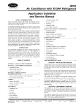
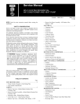
Screen Display Console
This is a sample of the WinCnc software display.
Menu Bar Pg. 14-17
Viewer Window Pg. 13
Tool Bars
Pg. 4 & 5
Command Line Pg. 6
Message Display
Window Pg. 6
Axis Window Pg. 3
Transit Speeds
Pg. 4
Jog Increments
Pg. 7
Console Transit/Jog Buttons Pg. 7 & 8
Custom Macro Buttons Pg. 10 & 11
Status Bar Pg. 3
Most machine functions are preformed from the display console buttons or from
keyboard commands. For reasons of simplicity and functionality, we will cover
the onscreen features. Once that is fully understood, covering some of the
deeper features of WinCNC controller found in the “Menu Bar” would give you a
clear understand of the potential of the Machine. But for a quick reference, page
numbers are provide for each of the program’s different components.
30
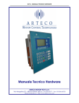
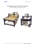
Screen Display Functions
The Axis Information Window
The Axis Window gives information about the status of your Machine.
Hardware or Software Limit Indicator
Red Arrow when limit is reached.
Left Side Arrow = Low Limit
Right Side Arrow = High Limit
Relative Mode Indicator [G92]
Green Light = Local Zero Set
Feedrate Override Slider Bar
Adjusts Feedrate manually.
Slide Up
= Increase in./min.
Slide Down = Reduce in./min.
Axis Feedrate Display
# = inches / minute
Axis Position Display
Zero Table Indicator [ Z –Axis]
Blue Light = Zero Table Set
Tool Measure on ATC only
Alternate Workspace Indicator [G55]
Blue Light = Alternate Workspace Active
X–Axis and Y–Axis only.
The Status Bar
The status bar is the label along the bottom of the WinCnc window that looks
similar to the one shown below. This bar provides the user with the status of
several features in WinCnc. Each section in the example below is labeled for
clarity.
Current File Directory
G00/G01 Mode Indicator
Current Tool Indicator
31
Current Job Line Number
G90/G91 Mode Indicator
Operations Tool Bar
The tool bar is a collection of shortcut buttons that perform specific actions. The
Toolbars in WinCnc are floating and can be positioned or docked to the user’s
preference. The image below shows both the standard and manual digitizing
toolbars both docked in the normal toolbar area.
Start Motion
Restart
Abort Motion
Pause/Continue
Open File
View History
Edit
Simulate
View
Soft Limits
Start Motion: This button will begin the command or job listed in the command
line.
Restart: Allows the operator to pick a job file and the line to start that file on.
This is useful for skipping over lines in a job file, or if you have aborted a job and
want to start back at the point you aborted from. If job is aborted, program
remembers the last line, and will return safely there.
Abort Motion: Aborts a running command or job.
Pause/Continue Motion: Pauses/Continues a running command or job.
Keyboard Shortcut: Space Bar
Open File: Opens a browse box used to open a job file.
View History: Opens the command history box, which allows operator to
execute a command used previously.
Edit: Opens the default editor specified in the WinCnc.ini file. WinCnc uses
notepad by default. The editor can be used to open job files, listed in the
command line, in the editor.
Simulate: Simulates a file to check for errors and run-time.
View: Opens a file for viewing in the viewer window.
Soft Limits: Enables/Disables Soft limit features.
32
Manual Digitize Tool Bar
If you have a digitize probe, the seven buttons on the manual digitization toolbar
are for use only with the Manual Digitize feature, and will only be visible after
showing the manual digitize toolbar under the View->toolbars section of the
menu bar.
Start a Manual
Add a Feed
Add a Rapid Move
Close Shapes
Add an Arc
Save
Undo
Start a Manual Digitized File: Starts a manual digitized file and enables the
manual digitize mode.
Add a Rapid Move: Adds a rapid move to the manual digitized file.
Add a Feed Move: Adds a feed move to the manual digitized file.
Add an Arc Point: Used to add arcs into a manual digitized file.
Close Shape: Used to close the last move in a shape without moving the probe.
Undo: Used to undo previous moves.
Save: Allows you save the manually digitized file in G-Code or DXF file format.
33
The Command Line
The Command Line is the user Input line for job file names or commands to be
executed.
The example above is showing a job named “WTEST.TAP” is ready to run. All
jobs end with the extension “.TAP”. Once a job title appears in the Command
Line, press the Enter key or the Start Motion button in the tool bar (pg. 8, 9) to
run the job from the current zero positions.
The only commands appearing in the Command Line, other than the current job,
are commands used for moving the cutting head to a specific point on the table
by inputting straight G-Code. Example: Move to position X+ 3”, Y+ 3”, Z+ 1”,
type at the command line X3Y3Z1 and press Enter. The machine will move to
this position. This is done when more accuracy is needed in locating the cutting
head over the cutting surface, than the arrow keys on the keyboard, or log
buttons, allow (for more information on keyboard commands see pg 14, 15).
Straight G-Code commands may also be entered here (a list of G-Code
commands is in Appendix I), but only one code at a time. Creating a “.TAP” file or
a “.MAC” (pg. 5) is best for running multiple code entries.
The Message Display Window
The message display window is the main output window displaying the
commands that have been executed, messages to the user, or errors that have
occurred during an operation.
34
Jog Increment Buttons
These buttons allow the operator to specify the increment of a jog move.
= 1 Inch
= 1/10 Inch
= 1/100 Inch
= 1/1000 Inch
Transit/Jog Buttons
These buttons allow the operator to initiate a manual transit or incremental jog
move from the Control PC display console. Press & hold a button for
continuous manual transit jog move on the selected Axis. Pressing the
button Momentarily will move the Axis in manual incremental jog mode only
one increment at a time. Pressing a button momentarily will move the Axis
according to the jog increment selected.
35
These actions can also be performed by using the arrow keys on your keyboard.
The Left and Right arrow keys are used to move the X-Axis in X-(left) or X+
(right) direction. The Up and Down arrow keys are used to move the Y-Axis
in Y+ (forward) or Y- (backward) direction. The “Page Up” and “Page Down”
keys are used to move the Z-Axis in Z+ (up) or Z- (down) direction. The
”Home” and “End” keys are used to move the W-Axis (Alternate Vertical
Axis) in W+ (up) or W-(down). The “Home” and “End” keys may also be used
to rotate a the R-Axis (Rotary Indexing Axis) R+ (clockwise) or R- (counter
clockwise) direction when the CNC System is equipped with a Rotary Axis. THE
“HOME” KEY COMMAND DOES NOT “HOME” ANY SYSTEM AXIS.
Axis
X- Axis
X- Axis
Y- Axis
Y- Axis
Z- Axis
Z- Axis
36
Direction
Keyboard
Console Button
Alternate Axis
Direction
Keyboard
Console Button
R- Axis
R- Axis
W- Axis
W- Axis
Transit Speeds Buttons
These buttons allow the user to specify the transit speed of the machine.
Fast
Medium
Machine w/ Stepper
Motors
800 (in/min)
100 (in/min)
Machine w/ Servo
Motors
1200 (in/min)
300 (in/min)
Slow
20 (in/min)
20 (in/min)
Transit Speeds
37
Custom Macro Buttons
The Custom Macro Buttons are custom control buttons which are shortcuts to
activate commonly used commands. Each button uses a Macro File or a .MAC
File installed in the control software. Following are some Custom Macro Buttons
that come installed with the Machine CNC System and the g-code used to
create them. Specific Macro buttons may vary with system model and options.
Home Synchronizes each Axis with WinCNC, and provides a
reference point for software limits. Software invisible limits
programmed into WinCNC to restrict the movement of any axis from
over traveling its’ workspace. When WinCNC Controller is started, the
display is set to the last known position. The G28 command must be
used to home the machine. G28 command (1) moves the Z-Axis up to
its high limit. (2) moves the X-Axis to its far left limit. (3) moves the YAxis to its forward limit. The Home Macro button uses the G28
command to home the system.
Go Home Raises any vertical axis (Z and W Axis), to machine zero
then returns the XY Axis to the Local Coordinate Zero.
ZeroZ Performs the same function as the ZeroXY macro button,
except placing a local zero on the Z axis only.
38
ZeroXY Creates a local zero at the current XY position. ZeroXY uses
the G92 command on the XY to create the Local Zeros. Although the
Machine Zero is still stored in memory, the Local Coordinate System
becomes active after using. A Machine Coordinate can still be
accessed by using the G-Code command G53 and the desired
position. Example: G53XYZ will take the machine to machine zero no
matter what local coordinate are set. Using the G53 command doesn’t
erase the Local Zeros, but uses the Machine Coordinate System
instead of the Local Coordinate System. (See page 2 - Local and
Machine Coordinate Systems)
Reset Will remove any local coordinates, tool measures, or Zero
Table boundaries that might cause WinCNC to give a boundary or
software limit error after the CNC routers table or sacrifice material
surface has been refinished, or an old tool as been replaced in a
Machine equipped with ATC (Automatic Tool Changer).
Zero Table Used with the Touchpad to create a software boundary.
This boundary is normally table top or top of the spoil /sacrifice
material. Zero Table sets a software boundary beneath the cutting
surface to prevent plunging a cutting tool too far below the work
material.
TouchTop Creates a Z local zero quickly and accurately on a cutting
material’s surface. Placing a local Z zero on the material surface is
necessary. It indicates where the cutting surface is located in the Z
plane. The procedure for using the TouchTop command is similar to
the Zero Table except the job material surface is measured instead of
the table top surface.
Calc. Quickly opens the Windows Calculator for when quick
calculations when necessary.
Menu Bar
39
The Menu Bar contains many of the main features of the WinCnc Software. It is broken down
into several generalized sections, as shown above. The following graphics display their options
and uses under each section. With a Standard Machine many of these opinions are not
available, and are not necessary to operate the machine. Some of these opinions are also
available as buttons on the WinCNC program window.
File Menu
Opens a file
Opens the editor (if a, editor opens filename is in command line)
Simulates a file running to check for errors and run time.
View a file in the viewer window.
Creates a home file at the current machine position.
For importing DXF and HPGL files.*
Exits WinCnc
*Note:The DXF and HPGL import feature of WinCNC should only be used the for simple design.
WinCNC does not compensate for tool diameter when converting these files. For design, where
intellegent tool pathing is important, use a compatible CAD/CAM program.
Configuration Menu
Starts the WinCnc.ini File Editor
Calibration Settings for D/A
40
Settings Menu
View Positions
View Home Positions
View Tool Positions
View Menu
View current Resolution settings for each axis.
View current Acceleration settings for each axis
View current Limit settings for each axis.
Vie
c rrent inp t stat s
Display Toolbars
Refreshes the screen.
Clears the message display window
Options Menu
Enable/Disable the Soft Limits Option.
Enable/Disable the Keyboard Transit/Jog
Control.
Used to Customize User Buttons.
Auto populate the command line with last
Command.
Enables/Disables the Auto run feature.
41
Units Menu
Set units of measurement to Inches.
Set units of measurement to Centimeters.
Set units of measurement to Millimeter
Millimeters.
Transit Menu
Set Transit speed to Slow
Set Transit speed to Medium
Set Transit speed to Fast
Jog Menu
Set Jog Increment to 0.001
Set Jog Increment to 0.01
Set Jog Increment to 0.1
Set Jog Increment to 1
Set Jog Increment to Custom
Help Menu
Activates the in Program help menu.
Opens the Updating Utility.
Opens the About WinCnc window.
42
About WinCnc
The About Box in the Controller software contains important information about
the specific software package. The About Box displays the security key serial
number, the software version number, the user level, the maximum number of
axis, the table size limitation, and which additional features the user has enabled.
If you do not have a feature enable that you would like or need, you can contact
Eagle Eye, Inc for an upgrade.
43
Viewer Window
The Viewer Window provides visual information about the status of the WinCnc
software and equipment. The Viewer Window also allows job previewing.
will also display a G-code file line by line as it is run by WinCnc. G0 moves and
G1 moves are distinguished by the color of the line in the Viewer Window. G0
moves are shown as a black dashed line. G1 moves are displayed as a solid
blue line. You can also re-center, and zoom in or out within the viewer.
Commands used for The Viewer Window:
To Preview a File:
With the file name in the command line select the “View” button under the “File”
menu, press Ctrl+V, or press the “View” button on the toolbar. The file will be
displayed line by line automatically when you run the file.
Viewer Window Adjusting controls:
Zoom in Incrementally – click left mouse button.
Zoom out Incrementally – click right mouse button.
Selected Zoom – hold down the left mouse button and drag box around area to
zoom in on.
Pan or re-center object – hold control and click either mouse button.
Reset Image – hold shift and click either mouse button.
44
Viewer Window Display
Job Preview
Local Zero
(Starting Point)
Machine Zero
Tool Location
(Red Dot)
45
Homing the System
Machine Zero: An absolute position located close the front left corner of the
table. The system finds its “Home” position or starting point for all Axis by
moving to its X-Low, Y-Low, and Z-High limit switches. This point is stored in
memory and all other points are created from referencing that position.
Use the Home button or type G28 then Enter at the “Command Line”,
for moving to the Machine Zero for all Axis. Use any time the system
started to synchronize WinCNC with each Axis.
Local Zeros: Axis starting positions which may be set any were within the cutting
area of the CNC System. This is normally set to the front, left corner of the job
material.
Use the ZeroXY button or use the G92, G92.1 or G92.2 commands to
set Local Zeros. (See the G-Code Command list for explanations)
Use the Go Home to return the cutting head to its’ Local Home
position for the X and Y-Axis. The Z or W-Axis will have to be reset at
this point with the Touchpad.
Local Zero / Home
Machine Zero / Home
46
Job Material
Using the Touchpad
The Touchpad is used to find the top surface height of the job material, and set
that point as local zero for the Z-Axis. This position is different on any cutting tool
and job material. Setting the material height between jobs saves time, and saves
material.
Completely stop the cutting head rotation before using the Touchpad.
Before running the Touchtop or Zero Table files, place the Touchpad on top of
the desired material surface. The Locate the cutting head tool over the
Touchpad. The Z -Axis will lower slowly until it contacts the Touchpad, then
raises up .75 inches off the material’s surface when it is complete.
Tool
Touchpad
Material Surface
Setting the material surface height manually
1. Using the Page Down key, carefully bring the tool tip down slowly to the
surface of the job material. Use the small incremental jog commands to finetune the position. Be careful do not gouge the job material.
2. At the command line, type G92Z, press the Enter key. Local Zero is set for
the Z-axis.
3. Use the Page Up key to Raise the Z-Axis cutting tool off of the job material.
47
G90 and G91 Modes
There are two different ways that WinCNC controller finds position once a start
point is established.
G90 Mode
G90 mode is called absolute mode. In G90 mode values specify positions. If the
X position is 20 and G0 X8 is specified the machine would move –12 inches in X
to X8.
In G90 mode the situation is different. The initial of the machine position will not
affect where the part runs since the first move will go to the absolute position
specified on the table. Instead of setting the machine position properly before
running a G90 program. This is the mode we recommend for the Machine CNC
router. Most G90 programs are written relative to a starting position of X0Y0 with
Z0W0 being the top of the job material. All that is then necessary to run the
program is to insure that the current Local Zero is set to match the program
before running.
Alternately Local Zeros may be set by shifting Machine Zero the desired
amount using G92.1 Using G92.1 it is not necessary to move to the job material
first.
G91 Mode
G91 mode is called relative or incremental mode. In G91 mode values specify
distances. For instance if the X position is currently 20 and G0 X8 is specified the
machine would move +8 inches in X to X28.
A G-Code program written in G91 mode may be run from any position. Since the
moves are relative, the starting position does not matter, the program will run
properly from any starting position. However to get the proper results the
machine must be set to the proper position in relation to the job material before
the piece is run.
The axis coordinate status does not have any effect on how the program runs. It
does however affect the coordinate display while the program runs.
48
Example
G90
Commands in G90 mode
G92.1X20Y20Z1
Move Local Zero 20” in XY and 1” above the table
The coordinate display shows the current position relative to the work piece.
When writing a G Code program the user must always remember to set a starting
point using the ZeroXY and set the Z or W zero at the top of the job material
using the Touchtop of ZeroZ macro buttons.
When running the program the machine is positioned to this starting point and
G92, the g-code used then the ZeroXY macro files, is used to set position to the
start position for the program. Alternately G92.1 may be used to shift Machine
Zero.
49
Keyboard Shortcut Commands
50
File Menu Shortcuts
Open
Enter(only when command line is blank), (Ctrl+0)
Edit
(Ctrl+E)
Simulate
(Ctrl+S)
View
(Ctrl+V)
Create Home
File
(Ctrl+H).
View Menu Shortcuts
Refresh View
(F5)
Clear
Messages
(Ctrl+C)
Options Menu Shortcuts
Keyboard
(Ctrl+K).
Soft Limit
(Ctrl+L)
Transit Menu Shortcuts
Slow
(F2).
Medium
(F3)
Fast
(F4)
Jog Menu Shortcuts
.001
(F6)
.01
(F7)
.1
(F8)
1
(F9)
Custom
(F10)
Help Menu Shortcuts
Help
(F1)
Tool Bar Shortcuts
ESC
Aborts the current file or command.
SPACE
Pauses or continues a paused file or command. Enter will also continue a
paused file or command.
TAB
Opens the command history box.
Ctrl+R
Opens the restart file box.
Feed Rate Override Shortcuts
Insert
Increases override rate
Delete
Decreases override rate
Ctrl+either
Resets feed rate to 100%. No override settings
Notes
51
Notes
52
Appendix I
Command Reference:
Here is a list all commands supported by WinCNC Controller.
Parameters in [Brackets] are optional.
Values:
XYZWIJ
Axis Specification
[X#] [Y#] [Z#] etc.
Axis values are specified with a decimal point. A value with no
decimal is read as an integer value. No value is equivalent to
specifying 0.
Example: XYZ is equivalent to X0Y0Z0.
F
Feed Velocity
F#
P
Stored Positions
Velocity is stored separately for Linear XY, Linear ZW. Arc’s
Rapid and Feed Velocity is stored separately for Linear
Moves. Independent velocities are stored based on the XYZW
specified in the line containing the F# command. Velocity is
specified in inches per minute.
Move to the selected stored position.
P#
H
Stored Home Positions
Move to the selected stored Home position.
H#
S
Spindle Speed
Sets the spindle speed to the given value.
S#
Example: F60 sets XY Feed Velocity to 60. G1 X F60 sets XY Feed Velocity to
60. G2 X2 F60 sets arc feed Velocity to 60. Feed Velocity changes affect all axis
in a Vgroup.
[]
Comment
Used to add comments to programs. A closing bracket is
optional.
Example: [This is a comment]
{}
Braces
Used to substitute axis or parameter values in a line of GCode. Internally defined variables as well as constant numbers
can be used within the braces. Following is a list of internally
defined variables and what they represent.
53
G Codes:
G0
G0.1
Rapid Move
G0 [X#] [Y#] [Z#] [W#]
Rapid Move with
Vertical Lift
G0.1 [X#] [Y#]
Moves to the position specified at Rapid velocity. G0 is modal.
After a G0 is executed lines with no g-code command are
executed as a G0.
First lifts all vertical heads then moves the position specified at
Rapid velocity then drops the vertical heads back to their
previous positions.
Example: X1Y1 is equivalent to G0 X1Y1 if mode is G0
G1
Feed Move
G1 [X#] [Y#] [Z#] [W#]
Moves to the position specified at Feed velocity. G1 is modal.
After a G1 is executed lines with no g-code command are
executed as a G1.
Example: X1Y1 is equivalent to G1 X1Y1 if mode is G1
Clockwise Arc
G2
G2 [X#] [Y#] [I#] [J#] [Z#]
[W#]
Counter Clockwise Arc
G3
G4
G3 [X#] [Y#] [I#] [J#] [Z#]
[W#]
Dwell
G4 X[#]
Moves to the position specified at Feed velocity. I is the X
distance to the center point. J is the Y distance to the center
point. If no XY move is specified a full circle is cut. If no I or J
is specified previous I J values are kept. Helical Interpolation is
supported in Level 2+ Only.
Moves to the position specified at Feed velocity. I is the X
distance to the center point. J is the Y distance to the center
point. If no XY move is specified a full circle is cut. If no I or J
is specified previous I J values are kept. Helical Interpolation is
supported in Level 2+ Only.
Stops movement for the time specified by the X value in
seconds. There is no limit to delay time. If no time is specified
then the machine will be stopped until the operator pushes
ENTER. Place a comment after the dwell to prompt the
operator.
Example: G4 [Ready To Start Section 2] Never use Dwell to stop the machine while changing
parts!Instead program a single part and use the TAB key at the Program prompt.This will repeat
the last part cut.
G9
Smoothing
G9 S[#]
Enables vector smoothing. S is smoothing factor, 1 being no
smoothing. Highest smoothing factor is machine dependent,
stepper machines typically use S5, and servo machines
typically use S1. Too high a factor can result in missed steps
or motor stalls. Smoothing can also be set in the WINCNC.INI
file using G09 = S#
G20
Set Unit to Inches
Converts unit of measure to inches.
G21
Set Unit to Centimeters
Converts unit of measure to centimeters.
G22
Set Unit to Millimeters
Converts unit of measure to millimeters.
G23
Return to last used unit
Returns to the last used unit of measure.
54
G28
G31
Return to machine zero
G28 [X] [Y] [Z] [W]
Stop file parsing
Moves specified Axis’s to Lo Limit for XY – Hi Limit for ZW.
Moves specified Axis’s to WINCNC.INI specs from limits.
Sets all Axis positions to 0. All Axis’ are moved if none are
specified.
Used with the M28 command to measure machine position
after touching a limit switch.
Example: L91 G1 Z-10 F20 M28 G31 M37 Z1
G43
G49
G50
G51
G53
G54
G55
G56
G57
Tool Length Offset On
G43 [Z] [W] [U] [V]
Tool Length Offset Off
Cancels tool length offsets. G49 alone turns all offsets off.
G49 [Z] [W] [U] [V]
Scaling Mode Off
Cancels the scaling mode.
Scaling Mode On
Enables the scaling factor. Scale each axis type based on
the values specified by X# Y# Z#. The object will be centered
based on the I# (X center) J# (Y) K#(Z). You can center all
axis using the C# line.
G51 [X#] [Y#] [Z#] [I#]
[J#] [K#] [C#]
Rapid Move
G53 [X#] [Y#] [Z#] [W#]
G54 Workspace
Rotational: G54 [X#] [Y#]
G55 Workspace
Rotational: G55 [X#] [Y#]
G56 Workspace
Rotational: G56 [X#] [Y#]
G57 Workspace
Rotational: G57 [X#] [Y#]
Chip Break Cycle
G73
G73 [X#] [Y#] [Z#] [R#]
[Q#] F#]
G80
End Drill Cycle
Drill Cycle
G81
Sets tool length offsets to the values set by the last M37
command. G43 alone turns all offsets on.
G81 [X#] [Y#] [Z#] [R#]
[F#]
Moves to the position specified at rapid velocity, ignoring tool
measures and local coordinates. G53 alone will lift all vertical
or type 3 axis.
Select the Z head. If G54 is commanded from G55, G56, or
G57 mode, the Z head will be moved to the current XY
position.
Select the W head. If G55 is commanded from G54, G56, or
G57 mode, the W head will be moved to the current XY
position.
Select the U head. If G56 is commanded from G54, G55, or
G57 mode, the U head will be moved to the current XY
position.
Select the V head. If G57 is commanded from G54, G55, or G56
mode, the V head will be moved to the current XY position.
Moves to XY specified at Rapid velocity.
On the first peck, moves to R retract height at Rapid velocity,
moves to Q peck depth at F Feed velocity, lifts 0.05” at Rapid
velocity to break the chip, moves to next peck depth at Feed
velocity. The cycle repeats until Z depth is reached. Then
moves back to retract height R at Rapid velocity. Without this
cycle, some materials can produce a long “stringer” which can
become a safety issue to the operator.
Used to disable the G81 Drill Cycle mode. Note: Switching to
G0 or G1 will also break out of the drill cycle mode.
Moves to XY specified at Rapid velocity.
Moves to R (clearing height) at Rapid velocity. Moves to Z
specified at Feed velocity. Moves back to R at Rapid velocity. F
allows you to set the feed rate.
55
Dwell Cycle
G82
G82 [X#] [Y#] [Z#] [R#]
[P#] F#]
Peck Drill Cycle
G83
G83 [X#] [Y#] [Z#] [R#]
[Q#] F#]
Moves to XY specified at Rapid velocity.
Moves to R (clearing height) specified at Rapid velocity.
Moves to Z specified at Feed velocity. If P is specified, bit
pauses that amount of time at the bottom of the hole, then
moves back to R at Rapid velocity. P is measured in
milliseconds (thousandths of one second). F allows you to set
the feed rate.
Moves to XY specified at Rapid velocity.
On the first peck, moves to R retract height at Rapid velocity,
moves to peck depth Q at Feed velocity, then moves back to
retract height at Rapid velocity. On each subsequent peck,
moves at Rapid velocity to within 0.05” of previous peck depth,
then moves at Feed velocity to next peck depth. Cycle
repeats until Z depth is reached. Then moves back at Rapid
velocity to retract height R. The F allows user to set the feed
rate.
G90
Absolute Mode
Can be specified with other G Codes on any line. XYZW
values from the current line forward are read as absolute
coordinates. IJ values are always relative to the current XY
position, not absolute positions, regardless of G90/G91 mode.
G91
Relative Mode
Can be specified with other G Codes on any line. XYZW
values from the current line forward are read as relative
movements from the current position.
G92
G92.1
G92.2
Set Local Coordinates
G92 [X#] [Y#] [Z#] [W#]
Shift MZ Coordinates
G92.1 [X#] [Y#] [Z#] [W#]
Shift LZ Coordinates
G92.2 [X#] [Y#] [Z#] [W#]
Used to specify a new coordinate system for running absolute
mode programs. Use G92 alone to restore the Machine
Coordinates. G92 X0 Y0 Z0 W0 sets the current position to
zero. G92 then restores the Machine Coordinates values.
Similar to G92 except that the coordinate system produced
shifts Machine Zero by the amount specified. This is useful
since a given local coordinate system can be set without
positioning the head to a certain position first. G92 X10 Y10
sets the absolute position X10 Y10 to X0 Y0 in local
coordinates. G92.1 may also be used to restore a single axis
to absolute coordinates. G92.1 X0 leaves YZW local
coordinates but sets X back to absolute coordinates.
Similar to G92.1 except that the coordinate system shift is
added to the current local coordinates instead of replacing
them. This is useful for ‘jogging’ a local position. If the Z head
has been set for running a G90 mode file but then needs to set
to cut .010” deeper G92.2Z-.01 will accomplish this with a
single command. Can be useful as a macro.
56
L Codes:
L0, L2
Ignored
Ignored commands are not executed but not flagged as errors.
L1
Spindle Speed Control
using the spin.mac
macro
Calls the spin.mac macro for spindle speed control. Spin.mac
must be a file in the WinCnc directory.
L3
L4
L10
L11
Set Home Position
L3 [X] [Y] [Z] [W]
Return To Home
L4 [X] [Y] [Z] [W]
Cut Array
L10 [R#] [C#] [X#] [Y#]
Set Axis Mapping
L11 [X] [Y] [Z] [W]
Stores current position of each axis specified. Values specified
are ignored.
Moves each axis specified to the last L3 position stored.
Values specified are ignored.
Sets up array cutting. Repeats all code following until the end
of the file or another L10 is reached. Code following L10 is run
until the end of file or another L10. Program pointer is moved
back to initial L10. The head is moved to the next column or
row specified by XY at rapid velocity. Cycle repeats until all
array points have been cut. L10 specified without RCXY
values can be used to end an array cut. Lines that follow will
not be repeated.
Allows re-mapping of axis inputs. Specify the axis’s that
should receive the input from XYZW in that order. Specify L11
alone to return to normal parsing.
Example: L11 XYWZ swaps the W and Z axis, L11 XYZW moves Z and W together.
L12
Set Axis Mapping
L12 [X] [Y] [Z] [W]
Allows re-mapping of axis inputs. Specify the axis’s that
should receive the input from ZW in that order. This command
works like L11 except that the XY inputs are skipped. Specify
L12 alone to return to normal parsing.
Example: L12 WZ swaps the W and Z axis, L12 ZZ moves Z and W together.
L13
L20
L21
L22
L23
Set Axis Mapping
L13 [X] [Y] [Z] [W]
Enable Soft Limits
L20 [X1, X2]
Disable Soft Limits
Set Lo Boundaries
L22 [X#] [Y#] [Z#] [W#]
Set Hi Boundaries
L23 [X#] [Y#] [Z#] [W#]
Allows re-mapping of axis on a pulse basis. This command
works like L11. Specify L13 alone to return to normal
mapping.
Enable Soft Limit and Boundary Checking: L20 X1 enables
Boundaries only. L20 X2 enables Soft Limits only. L20 alone
enables both.
Disable Soft Limit and Boundary Checking Soft Limits and
Boundaries are used to define a cutting area which is checked
during parsing of a file or command. This effectively keeps the
machine from moving out of a defined area. L21 disables Soft
Limit and Boundary checking.
Set Lo Boundaries to values specified. If no values are given
then all Lo Boundaries are set to Wincnc.INI defaults.
Set Hi Boundaries to values specified. If no values are given
then all Hi Boundaries are set to Wincnc.INI defaults.
57
L28
Set Position
L28 [X#] [Y#] [Z#] [W#]
Sets Machine Coordinates. Machine Coordinates specify the fixed machine
zero point for your machine. L28 is normally used only to write a custom
homing program. L28 does not move the machine, but sets the current
position to the values specified. Use G92 to set a local coordinate system for
running absolute mode programs from any table position.
L30
Knife Mode On
Enables support for the Knife Mode.
L31
Knife Mode Off
Disables support for the Knife Mode.
L32
Saw Mode On
Enables support for the Saw Mode.
L33
Saw Mode Off
Disables support for the Saw Mode.
L34
L35
L40
L50
AutoAuxOut Enable
L34 [D#]
AutoAuxOut Disable
L35[D#]
Feed Rate Override
L40 [P#]
Generate a Set
Frequency
L50
Enables an auxiliary output that will turn on during G1/G2/G3 moves, and will
turn off for all other moves. L34D# sets the dwell time in seconds used when
the channel is set to on and L35D# sets the dwell time in seconds when the
channel is set to off. When the ‘D’ parameter is used with the L34 command
the “AutoAuxOut” mode does not change. L34 parameters are set in the
WINCNC.INI file by the “Autoaux =” line.
Disables the auxiliary output that is turned on by the L34 command. L35D#
sets the dwell time in seconds when the channel is set to off. When the ‘D’
parameter is used with the L35 command the “AutoAuxOut” mode does not
change.
Allows user to set the feed rate override by command. P must
be within the bounds specified in the ini file. If not, the
command is ignored. The L40 command without a P# resets
the feed rate to the default.
Generates a set frequency using the ISA 7120 card where F#
is the number of desired pulses per second. L50 alone will
stop the output signal.
L50 [F#]
L51
Set D/A
L51 [V#] [P#] [S#]
Sets the output voltage for DA. The V parameter is used to
set the DA by voltage, the P to set the DA by a Percentage,
and the S is used to set the DA by spindle speed. ONLY 1
PARAMETER CAN BE USED.
L53
Set Vertical Head
Height
Raises all vertical heads as high as possible while keeping the
bits at equal height.
L55
Pump Velocity Mode On
Enables velocity matched pump control.
L56
Pump Purge Mode On
Sets pump to purge mode.
L57
Pump Off
Stops the pump.
L58
Pump Off with Auto
Reverse
Stops the pump, using auto reverse.
L59
L61
Set Up Pump Max
L59 [M#]
Set Laser Controller
Power
L61 [W#]
Sets the pump max to the specified M parameter.
Sets the power of the laser controller using the RS232
connection. The W parameter can be any value from 0 to 100.
Requires lasercont = setting.
58
L70
Re-Enter Last
Command
Measures the Surface
L82
L82
L82 [Z#]
L83
Measures Z Depth
L83 X[#] Y[#]
When L70 is used in a file the last used command will
automatically be re-entered on the command line after file
completion.
L82Z# measures the surface with the probe and sets the
measured point to the Z value given. L82 alone will set the
measured point to Z0.
L83 command will do a one-shot Z probe at the specified
location, and record the XYZ position values in a comma
delimited text file named scan.csv. Where X# and Y# specify
the (X,Y) coordinates to move to before doing the depth probe.
L90
One Time Absolute
L90 is used in a command to specify G90 coordinates on one
line without changing program mode to G90.
L91
One Time Relative
L91 is used in a command to specify G91 coordinates on one
line without changing program to G91.
L92
110
Cancel G92 Restore
L92
Tool Change
L110 [T#]
L111
L111.1
Test Tool Number
L111 [T#]
Test Tool Number with
Dual Tool Changers
The current G92 Local Coordinate system is saved every time
a program is started or a sub-program is called using M98.
When the program is finished the original G92 system is
restored. This is not desirable if the program is being used to
preset a system configuration for other programs. L92 causes
the normal G92 Coordinate restore to be skipped after the
program containing the L92 is finished.
Sets current tool number for machines with an automatic tool
changer. The tool number is available as {TP1} in subsequent
commands.
Run next line if tool number is equal to T#
Run next line if both tool numbers are equal to T#
L111.1 [T#]
L112
L113
Test Tool Number
L112 [T#]
Spindle Speed
Conditions
L113[L#][H#][V#]
L120
L201
Skip next line if tool number is equal to T#
Skip the next line if the V# is not greater than the L# and less
than the H#.
L120 [T#]
Sets current tool number for machines with an automatic tool
changer. The tool number is available as {TP2} in subsequent
commands.
Set 201 Signal
Command
Sets the command used with the 201 signal type.
Tool Change
L201 [Command]
L202
Set 202 Signal
Command
Sets the command used with the 202 signal type.
L202 [Command]
59
210
Selects Alternate Low
Limits
Selects axis to use alternate low limits
L210 [X] [Y] [Z] [W]
L211
Selects Alternate High
Limits
Selects axis to use alternate high limits
L211 [X] [Y] [Z] [W]
L212
L213
L214
Selects Primary Limits
L212
Dual Axis, Select Main
L213 [X] [Y] [Z] [W]
Dual Axis, Select
Secondary
Selects the Primary Limits for all axis.
Selects the main motor on a dual motor axis.
Selects the secondary motor on a dual motor axis.
L214 [X] [Y] [Z] [W]
L215
Dual Axis, Select Both
Axis
Selects both motors on a dual motor axis.
L215 [X] [Y] [Z] [W]
Laser Power Setting
Using the L249 command allows you specify the laser power.
L249 [P#]
Example: L249P50 (sets laser power to 50)
L250
Vector Laser Off
Disables vector laser cutting.
L251
Vector Laser On
Enables vector laser cutting.
L249
L251.1
L300
L301
L400
L401
Laser Dwell
L251.1 [D#]
Lock Axis
L300 [XYZW]
Unlock Axis
L301 [XYZW]
Create Home File
L400
Recall Positions
L401
Turns laser on for specified period of time.
Locks specified axis motion. Any motion commanded to a
locked axis will be ignored.
Unlocks specified axis motion.
Creates a home file at the machines current position.
Moves all axis to the positions where they were at previous to
the last file ran.
60
L500
Store Absolute
Positions
L500 [X, Y, Z..] [P H T] L#
C# N”Pos Name”
[X, Y, Z..] – axes to set positions for if none specified then all axis positions
are stored.
[P H T] – Type of Position (P)osition, (H)ome Position, (T)ool Position. Can
only use one.
L# - 0 no vertical head life, 1 include head lift.
C# - Clearance for vertical heads if L1.
N”Name” – Name for specified position. Must be less than 16 characters long.
[X, Y, Z..] – axes to set positions for if none specified then all axis positions
are stored.
Store Local Positions
L501
L501 [X, Y, Z..] [P H T] L#
C# N”Pos Name”
[P H T] – Type of Position (P)osition, (H)ome Position, (T)ool Position. Can
only use one.
L# - 0 no vertical head life, 1 include head lift. Default is L1.
C# - Clearance for vertical heads if L1.
N”Name” – Name for specified position. Must be less than 16 characters long.
L800
L801
Disable Probe
L800
Enable Probe
L801
Scan Given Rectangle
L802
L803
Uses an up, down, side to side
probe typeL802 [X# Y# I#]
Disables the probe while transiting.
Enables the probe while transiting.
Scans a given rectangle XY with an increment of I in an up,
down, and side to side style scan.
Scan Given Rectangle
Uses an up – down probe
type
Scan a given rectangle XY with an increment of I in an up
down style scan.
L803 [X# Y# I#]
61
M Codes:
Controls auxiliary outputs. Channel specified by # is turned on.
Port and bit addresses are setup in WINCNC.INI.
M11
Auxiliary Output On
M11 [C#]
Note: For use with a Drill Bank
A d# can be added to the M11 command for use with a
drillbank. The d# is the binary number of channels up to the
n# specified in the drillbank line to turn on.
Example:M11D7 would turn on the first 3 channels of a ten
channel drill bank.
M12
M13
M14
M17
M18
M17.1
M17.2
M18.1
M28
M29
M37
Auxiliary Output Off
M12 [C#]
Auxiliary Output On
M13 [C#]
Auxiliary Output Off
M14 [C#]
Pause Until Input On
M17 [C#]
Pause Until Input Off
M18 [C#]
Run Next If Input On
M17.1 [C#]
Run Next if Aux Out is On
M17.2 [C#]
Run Next If Input Off
M18.1 [C#]
Controls auxiliary outputs. Channel specified by # is turned off.
Port and bit addresses are setup in WINCNC.INI.
Same as M11, except the output is turned off without pausing
motion.
Same as M12, except the output is turned off without pausing
motion.
Wait for channel specified by # to come on. Port and bit
addresses are setup in WINCNC.INI.
Wait for channel specified by # to go off. Port and bit
addresses are setup in WINCNC.INI.
Run next command only if channel specified by # is on. Port
and bit addresses are setup in WINCNC.INI.
Run the next command only if channel specified by the # is on.
Port and bit addresses are setup in WINCNC.INI.
Run next command only if channel specified by # is off. Port
and bit addresses are setup in WINCNC.INI.
Disable Limit Abort
M28 is used to write your own home program instead of using
G28 to home the machine. CNC Controller normally aborts a
program when a limit switch is encountered. Adding M28 to a
G0 or G1 command disables the program abort and instead
stops the limited axis while allowing other axis’s to continue.
Limit Cushions are disabled while using M28 so any move
done with M28 should be done slowly to avoid machine
damage. M28 must be specified on each line separately.
Disable Limit Abort
M29 is used to write your own home program instead of using
G28 to home the machine. Adding M29 to a G0 or G1
command disables the program abort and instead stops the
current G Code line but continues on the following line. M29
must be specified on each line separately.
Measure Tool
M37 [Z#] [W#] [U#] [V#]
M37 is used to set Tool Length Offsets. The end of the tool is
first set to a known position. M37 is then specified to set the
tool length offset.
62
M37.1
Measure Tool for
Calibrating G37
M37.1 [Z#] [W#] [U#] [V#]
M37.1 is used to store a tool measure in the TM1 variable.
This command is used primarily with calibrating G37 for
automatic tool measuring.
Example: Jog the Z head to the spoilboard. Enter M37Z0 to the Z work coordinate to 0.
Once Tool Length Offsets are set, Boundaries may be used to insure that the table is not routed
by accident. Normally zero values are set to the top of the spoilboard. Use G92 to set material
thickness if programs reference zero from the top of material. This eliminates re-measuring tool
for different thickness materials. G43 and G49 are used to enable and disable offsets.
M98
M98.1
M99
Subprogram Call
M98 <filename>
Subprogram Call
M98.1 <filename>
End Subprogram
Run a subprogram. A subprogram may be any G Code file. Control is passed
back to the calling program when finished. To run a G90 mode subprogram
from any position on the table use G92X#Y#Z#W# to set the local coordinates
at the beginning of the file.
Same as M98, except line numbers in the subprogram are not counted. This
is most useful for macros that call subprograms.
Ends a subprogram.
Machine Codes:
M3
Turns Spindle On
M5
Turns Spindle Off
This command will turn on the spindle, if the Machine is
equipped with the automatic spindle feature. Use the ‘S’
command, above, to set speed of spindle in RPM.
This command will turn off the spindle, if the Machine is
equipped with the automatic spindle feature.
Change Tool
T[tool number]
Example:
T1- Changes tool One
T2- Changes tool Two,
etc.
TC
Loads Tool
TU
Unloads Tool
Enter T and the tool number to change tools on a Machine
Equipped with ATC.
Loads current tool if the active tool is unloaded. Only on Eagle
Eyes equipped with ATC.
Unloads current tool into the tool holders. Only on Machine
equipped with ATC.
63
Troubleshooting
1. The machine is cutting circles or arcs that are oblong or not true circles.
A1. Check for looseness in the axes by pushing on the different axes while
the control box is on, but make sure that the cutting head is disengaged.
Once the looseness is found, adjust the axis bearing so they are tight
against the drive rails, but not so tight the axis cannot move freely. Call
Eagle Eye tech support if you need assistance.
2. When I start the software I try to move or home the machine and I get an
“Abort Enable I” massage.
A1. Make sure that the machine is plugged in with the controller engaged
and the Emergency Stop disengaged.
A2. Make sure the 37-pin connector cable is properly connected to the
machine into the computer’s blue 37-pin connector port.
A3. Call Eagle Eye tech support, professional assistance is required.
3. I hear noise from the motors but that axis is not moving. Or moves to a
certain point and stops. But the other axis will move fine.
A1. Check gears and tracks to make sure nothing is obstructing the
movement of the machine. Or the bearings need adjustment.
A2. Other unknown cause, possible defective component in control
system, contacting Eagle Eye is recommended.
4. In WinCNC I get the message “Abort limit switch ……” appears in middle of
cut file with the hard limits have clearly not been touched.
A1.
Check Emergency Stop button and make sure it is not presses.
A2. You machine is getting electrical noise that causes the limit switches
to trigger. Call Eagle Eye tech support for assistance.
5. One axis’s motor will move but it shutters, or moves a short distances and
spins back a little then repeats this process again, or the axis moves to a
curtain point then stops.
64
A1. Check and make sure that there is nothing blocking the movement of
that axis. Check the gears and ball screw (if problem is on the Z axis) for
any debris. If you see debris, remove it. If you cannot see any debris,
turn off your control box and wait a few seconds, try moving the axis by
pushing on that axis in the direction of the problem, in the case of the Z
axis turn the ball screw with your finger. If the control box is off and the
axis in question will not move, or comes to a curtain point and stops
something is definitely blocking one of the gears of rails. Closer
investigation is recommended to make sure nothing to in the gears or
rails.
65
CONSULTING
SALES
SUPPORT
13555 Back Valley Road
Sale Creek, TN 37373
423-228-2349 ph
423-228-2346 fax
www.eagleeyecnc.com
www.youtube.com/eagleeyecnc
[email protected]