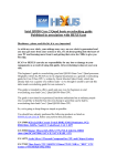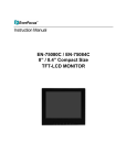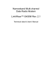
1
SERVICE MANUAL
FA9M068002
TRIUM 110
R
E
V
I
S
I
O
N
S
+:
(:
FAX:
V A: Création L. LUCE
E
R
S
I
O
N
S
05/02
Rédigé par
Vérifié par
Approuvé par
Written by
Checked by
Approuved by
L. LUCE
J. J. DEBEY
G. LEBASTARD
Mitsubishi Electric Telecom Europe S.A.
After Sales Services
Z.A. Pigeon Blanc, 35 370 St Germain du Pinel
+33 (0)2 99 75 71 00
+33 (0)2 99 75 71 47
Version A
Date: 05/02
Service Manual
Trium 110
CONTENTS
1 General description
3
1.1 Description of the kit
3
1.2 Additional Accessories
4
2 Assembly
6
2.1 Exploded diagram of M6A
6
2.2 Spare part list
6
2.3 Disassembly and Assembly Instruction
7
2.3.1 Disassembly Instruction
2.3.2 Assembly Instruction
7
7
3 Download
7
3.1 Download of Software and settings
4 Basic Adjustment
7
9
4.1 Equipment installation
9
4.2 Basic Adjustment
10
4.2.1 Power Adjustment
4.2.2 RSSI control.
10
10
5 Block Diagram
11
6 Reporting file
11
7 Repair Logigrams ( to be completed )
12
Version A
Date: 05/02
1/22
+:
Mitsubishi Electric Telecom Europe S.A.
After Sales Services
Z.A. Pigeon Blanc, 35 370 St Germain du Pinel France
(:
+33 (0)2 23 55 16 30
FAX:
+33 (0)2 99 75 71 62
Service Manual
Trium 110
8 Trouble Shooting help guide
12
9 Hardware description
14
9.1 Power management
14
9.1.1 Power Supply
9.1.2 Battery management
9.1.3 Power on/off
14
15
16
10 RF Section.
17
10.1 Frequency range.
17
10.1.1 E-GSM Frequency :
10.1.2 DCS Frequency :
17
17
10.2 Synthetiser Circuit Description.
18
10.3 RF Block Diagram.
19
10.4 Reception
19
10.4.1 Reception Block Diagram.
10.4.2 Description of Reception Block Diagram
10.5 Transmission.
20
10.5.1 Transmission Block Diagram.
10.5.2 Description of Transmission Block Diagram.
10.5.3 Power Control.
11 Personal Notes
Version A
Date: 05/02
2/22
19
20
20
20
21
22
+:
Mitsubishi Electric Telecom Europe S.A.
After Sales Services
Z.A. Pigeon Blanc, 35 370 St Germain du Pinel France
(:
+33 (0)2 23 55 16 30
FAX:
+33 (0)2 99 75 71 62
Service Manual
Trium 110
1
General description
M6A+ product is based on MARS product
1.1
Description of the kit
Commercial Name
TRIUM 110
Project Development Name
-
TRIUM 110 : Standard version
-
TRIUM110 m: For messaging, EMS
version
-
TRIUM 110 p: For play, EXEN
version
CUPID
MT 360
PICTURE
Main features:
Hand phone working with E-GSM/DCS networks
Hand phone including a WAP Browser 1.2.1 (Wireless Application Protocol )
Tri-codec Voice Encoding: Full Rate, Enhanced Full Rate and Half Rate
Integrated Hands-free
Integrated antenna (fixed in the case)
SMS (Short Message Service) with T9 (predictive text input)
Polyphonic melodies
Currency converter
Euro character managed (TBC)
Calculator
Clock/Date and Alarm
EXEN game
EMS ( Enhanced Message Sending )
Dimension and battery feature:
Weight: 110g (including battery )
Dimension: 116mm x 44.7mm x 25.2mm
Talk Time: Up to 2h09min
Standby Time: 165h
Call management:
Up to 254 number stored in SIM card (depending on the Software and the SIM card)
100 names with 3 telephone numbers each and associated icons (VCARD)
Version A
Date: 05/02
3/22
+:
Mitsubishi Electric Telecom Europe S.A.
After Sales Services
Z.A. Pigeon Blanc, 35 370 St Germain du Pinel France
(:
+33 (0)2 23 55 16 30
FAX:
+33 (0)2 99 75 71 62
Service Manual
Trium 110
4 items are included in the standard kit:
•
•
•
•
Cupid main unit
Li-Ion main battery (3.8V – 800mAh)
AC/DC Adapter for battery rapid charging
User manual
Difference with MARS & M6A*
Features
Hardware
Flash Memory
Memory
Back up battery
Mechanical
Handstrap
LED indicator
Cupid
M6A*
MARS
Flash 2Mbytes
Flash 2Mbytes
No
4 Mbytes multi-bank
None
No
2 Mbytes
EEPROM or Serial-Flash
Yes
Yes
No
Yes
No
No
Yes
* M6A: AURA, MYSTRAL, ODYSSEY
1.2
Additional Accessories
Code article
FK8A001910
FK8A001810
FK8A001710
FK8A002710
FS2F006410
FK8C000110
To be defined
FK8T000110
FK8T000310
FK8E000210
FK8E000110
To be defined
Désignation
AC/DC AU
AC/DC EU
AC/DC UK
AC/DC Chine
Battery M6A+
CLA M5
simple hand-free M5
PC cable Download professional
PC cable commercial Mars/Neptune
Headset FM radio
Standard Headset
Carrying Case
Ref Product
MA0504
MA0501
MA0502
MA0503
MA0632
MA0513
MA0638
MA0524
MA0571
MA0512
MA0509
MA0605
This is a typical list, also the “Spare Part List ”delivered by Mitsubishi is the official document .
Version A
Date: 05/02
4/22
+:
Mitsubishi Electric Telecom Europe S.A.
After Sales Services
Z.A. Pigeon Blanc, 35 370 St Germain du Pinel France
(:
+33 (0)2 23 55 16 30
FAX:
+33 (0)2 99 75 71 62
Service Manual
Trium 110
FRONT PANEL
MA 0640
COVER BATTERY
MA0604
BATTERY
MA 0632
MA0503
MA0504
MA0505
MA0502
MA0501
Simple Hand free
MA0638
Professional MA0524
Enhanced MA0571
MA0514
MA0512
To be defined
Standard MA0509
Head set
With button
To be defined
MA0513
MA0605
NECK STRAP MA0606
HAND STRAP MA0607
Version A
Date: 05/02
5/22
+:
Mitsubishi Electric Telecom Europe S.A.
After Sales Services
Z.A. Pigeon Blanc, 35 370 St Germain du Pinel France
(:
+33 (0)2 23 55 16 30
FAX:
+33 (0)2 99 75 71 62
Service Manual
Trium 110
2
Assembly
2.1
Exploded diagram of M6A
15
16
12
7
6
5
2
1
17
14
11
8
3
2.2
9
13
10
4
Spare part list
Item
1&2
3
4
5
6
7
8
9
10
11
12
13
14
15
16
17
Not Identified
Not Identified
Not Identified
Description
Window Assy M6A+
Front Panel M6 MT360
Screw PI TITE Head TPR N°02*8 ZBL
Cover Assy M6A+
Multiactors (3/1) M6A+
LCD Assy M6A+
Keypad M6a+
Micro Assy M5 MA/NE
Connector I/O M5 MA/NE
Screw PI TITE BENTZ Head TPR N°02*6
PCA test M6a+ (not available as spare part)
Motor Vibrator M5 MA/NE
Connector Battery M6A
Case M6A+
Battery M6A+
Battery Cover M6A+
Cap RF M5 MA/NE
Label Art (10 x 21) same as MA/NE
Label IMEI same as MA/NE
Reference
? following the colour
FK1W00951A
FK1B002410
? following the color
FS2F005810
FS13115410
FK1K002010
FS2E001410
FS2E001310
FK1B001510
FS2E001710
FS2F000310
? following the colour
FK1N027910
FS2E003610
FS2D003110
FA9L012210
This is a typical list, also the “Spare Part List ”delivered by Mitsubishi is the official document .
Version A
Date: 05/02
6/22
+:
Mitsubishi Electric Telecom Europe S.A.
After Sales Services
Z.A. Pigeon Blanc, 35 370 St Germain du Pinel France
(:
+33 (0)2 23 55 16 30
FAX:
+33 (0)2 99 75 71 62
Service Manual
Trium 110
2.3
Disassembly and Assembly Instruction
2.3.1 Disassembly Instruction
The procedure for mobile disassembly is described in the instruction GFZ13136904 – TRIUM 110
Disassembly (M6A+ Cupid).
2.3.2 Assembly Instruction
The procedure for mobile assembly is described in the instruction GFZ13136903 – TRIUM 110
Assembly (M6A+ Cupid).
3
Download
The data are divided in two parts: the software and the settings.
Currently the Mitsubishi software ( .bin file ) is downloaded into the Flash and the setting ( . pso file ) is
downloaded into an EEPROM or Serial Flash.
The M6A+ mobiles does not use EEPROM but a Flash Data and the setting are not in .pso extension
but in .psb (as M6A). The main consequence of this change is that the new setting file . psb MUST
BE DOWNLOADED WITH IPL TRIUM.
In conclusion, with the M6A product, the software and the setting can be downloaded in the same time
by using IPL Trium.
3.1
Download of Software and settings
The configuration to download software is :
Main unit
switched OFF
MT Tool
V103.02
or higher
To COM 1
Professional PC cable M5
MA/NE : FK8T000410
Launch MT ToolsV103.02 or higher, select the “Mobile Type M5-M6A” and then launch IPL Trium in
download/download software menu.
Version A
Date: 05/02
7/22
+:
Mitsubishi Electric Telecom Europe S.A.
After Sales Services
Z.A. Pigeon Blanc, 35 370 St Germain du Pinel France
(:
+33 (0)2 23 55 16 30
FAX:
+33 (0)2 99 75 71 62
Service Manual
Trium 110
Selection File
When IPL Trium is launched, the software or setting download is selected by choosing “Application
File”or “Personalization File”
Select the .bin file or .psb file or both, connect the PC cable to a switched off mobile, hold the power
button and click on “Start download”, the download starts when the back light blinks.
At the end of a successful download, the mobile displays “Download success ”.
Version A
Date: 05/02
8/22
+:
Mitsubishi Electric Telecom Europe S.A.
After Sales Services
Z.A. Pigeon Blanc, 35 370 St Germain du Pinel France
(:
+33 (0)2 23 55 16 30
FAX:
+33 (0)2 99 75 71 62
Service Manual
Trium 110
4
Basic Adjustment
For M6 family, test mode is not directly possible from the mobile, indeed relevant software is available
on PC only.
Thanks to the new generation of MT Tools (MT Tools 2000), we can either repair Level 2 or Level 3.
4.1
Equipment installation
RADIOCOMMUNICATION TESTER
Mobile without battery
GPIB Connection for Autotest only
(not requested for test mode)
CORDON M5 RF SMA M/SMA M
(F5CN000210)
M5 RF CABLE SMA L100
(F5CN000310)
External supply
4.5V
NSMA ADAPTATOR MALE
(F5CN000410)
M5 Interface Cable
F5CN000110
ITSU
M4 /M5 Interface Box
FT7Y009410
Serial Cable
FT7Y002110
The test mode is used to control or adjust mobile parameters.
You must have the following requirements :
•
•
•
•
•
•
•
Radio-communication tester
M5 RF cable
M5 Interface cable
M4 / M5 Interface Box
Serial Cable
Computer under Windows 95 minimum (PII 350 MHz 64 Mb recommended)
An ampermeter can be installed between the external supply and the interface box to check the
mobile consumption.
Version A
Date: 05/02
9/22
+:
Mitsubishi Electric Telecom Europe S.A.
After Sales Services
Z.A. Pigeon Blanc, 35 370 St Germain du Pinel France
(:
+33 (0)2 23 55 16 30
FAX:
+33 (0)2 99 75 71 62
Service Manual
Trium 110
4.2
Basic Adjustment
Use MT Tools 2000 1(Vers.103 Ed.02 or higher) to set all the parameters.
4.2.1 Power Adjustment
Each mobile is adjusted in the factory and the TX parameters (Power Control Level values and ramping values)
are stored in the Flash Data (IC202)
About the adjustment value of TX Power, see the following table.
E-GSM
Ch-62
PCL
5
6
7
8
9
10
11
12
13
14
15
16
17
18
19
Power Level
(dBm)
33
31
29
27
25
23
21
19
17
15
13
11
9
7
5
DCS
tolerance
Ch-698
PCL
0
1
2
3
4
5
6
7
8
9
10
11
12
13
14
15
+/-2dB
+/-3dB
+/-3dB
+/-3dB
+/-3dB
+/-3dB
+/-3dB
+/-3dB
+/-3dB
+/-3dB
+/-3dB
+/-5dB
+/-5dB
+/-5dB
+/-5dB
Power Level
(dBm)
30
28
26
24
22
20
18
16
14
12
10
8
6
4
2
0
tolerance
+/-2dB
+/-3dB
+/-3dB
+/-3dB
+/-3dB
+/-3dB
+/-3dB
+/-3dB
+/-3dB
+/-4dB
+/-4dB
+/-4dB
+/-4dB
+/-4dB
+/-5dB
+/-5dB
4.2.2 RSSI control.
Set your radiocommunication tester at a given reference and check RSSI :
REF Gene
-83.5 dBm
-60.5 dBm
RSSI
27 +/- 4
50 +/- 4
1
See Manual FA9M0640
Version A
Date: 05/02
10/22
+:
Mitsubishi Electric Telecom Europe S.A.
After Sales Services
Z.A. Pigeon Blanc, 35 370 St Germain du Pinel France
(:
+33 (0)2 23 55 16 30
FAX:
+33 (0)2 99 75 71 62
Service Manual
Trium 110
5
Block Diagram
SIM
Connector
GSM
Radio
Module
Keyboard
Radio
Interface
IC300
ONE-C
1.2
BUS
controller
Code
Flash
LED
Keyboard
JTAG/DAI
Data
Flash
I/
O
GPIO
PC cable
UART 1
RAM
Flux Control
SPI bus
External
Audio
LCD
controller
Micro
3 tones
IC
C
o
n
n
e
c
t
o
r
IPD
Charge
r
Li-Ion
Battery
Switches
&Filters
Amplifier
Speaker
LCD
Display
IPD
Intergrate Power Device IC100
LED
2.8VD
2.8 ANA
2.8V AUD
2.5VD
2.5 ANA
REG2
REG80
2.8RTC
6
Reporting file
The default and the results of the mobile repairing are saved in a data base using MT Tools and the
normalized codes in order to achieve quality reports ( see FA9M0640 & FA9M074410 ).
Version A
Date: 05/02
11/22
+:
Mitsubishi Electric Telecom Europe S.A.
After Sales Services
Z.A. Pigeon Blanc, 35 370 St Germain du Pinel France
(:
+33 (0)2 23 55 16 30
FAX:
+33 (0)2 99 75 71 62
Vibrator
Service Manual
Trium 110
7
Repair Logigrams ( to be completed )
The repair logigrams are achieved after few mobile returns to the Mitsubishi’s after sales service.
Then these logigrams are delivered in FI instructions form to the repair centers via E-mail.
8
Trouble Shooting help guide
Defects observed
Measure/Investigation
Component no good
correctives action
CHARGING PROBLEM
Charge consumption:
Start around at 125mA, displays “Charging”, fall over between 520 to 580mA with back light, then fall around 450 to 500mA.
Mobile displays “Check battery”
Check J101, soft upgrade,
change TR112
Change J103, Check J101
Visual check: connector J103 broken
J103
Mobile display “incorrect Voltage”
Mobile display “incorrect Voltage” and J103 & J101 already
changed
Mobile displays “Mitsubishi testmode”
Check J103 & J101
Check R126, TR103
TR112 & D117
Change IC300
Check the multiactor connection
multiactor
During a test call on network, audio reception defect
In a test call network; micro, receiver and speaker already
changed
Good in a test call network but noisy in a real call
Micro, multiactor
Key sound no good
Soft upgrade
Frozen LCD
A wave can be seen during the display
Incomplete display
Informations missing during the display
IC300
Change LCD or LCD
connector
Change the defected LEDs
Check J201 soldering
Change J201 if broken or
twisted
change LCD
Change J201
Same consumption
Check Battery
No charging
Incorrect Voltage
Incorrect Voltage
Mitsubishi Testmode
Mobile consumption stay at 120mA
AUDIO PROBLEM
Tone test no good
Noisy reception
Noisy reception
Noisy reception
Key sound
IC300
IC300
DISPLAY PROBLEM
Check the LEDs
Backlight
White screen
Inconsistent display
Freezing display
No display
Wrong characters
Nothing displayed in normal mode and in testmode
Character problems during the display
The display stop during the On/Off process
Wrong characters on LCD
Soft updating
Soft upgrade, change
IC300
Soft upgrade
Enter lock code
Setting upgrade
Mobile turn off when a key is pressed
Error message
Version A
Date: 05/02
12/22
+:
Mitsubishi Electric Telecom Europe S.A.
After Sales Services
Z.A. Pigeon Blanc, 35 370 St Germain du Pinel France
(:
+33 (0)2 23 55 16 30
FAX:
+33 (0)2 99 75 71 62
Service Manual
Trium 110
LOCATION UPDATE
No service EGSM & DCS
TX & RX good in test mode
Soft updating
No service EGSM & DCS
After a soft updating still no good
IC300
No training sequence
Check VREF3, if parasite exist
Change C155, check C101
No training sequence
No modulation
IC401
RX level no good
With a –83db signal check the RSSI (= 27 ±4),
RSSI good (10< <100) and the mobile lose the network
RSSI no good, RSSI > 100
RX level no good
RSSI no good, RSSI < 10
SW700
RX qual no good
IC300
Soft updating, IC300,
IC401
RX level no good
RX Qual > 2
Call stop at any time
Call drop
IC300
IC300
POWER ON PROBLEM
No power on
No power on
No power on
No power on
Switch off itself
“Checksum error” during a software download
( Keypad flashing )
Check the position of the key rubber
Check J101 (batt connector) broken, missing
Check the contact with the board
Mobile turn on if the power key is pressed continuously, and
switch off when the power key is released
Mobile turn off itself
Flash (IC200) defective
(soldering)
Replace the key rubber
J101
IC300 (soldering)
Soft updating, check J101
Normal consumption in TestMode : 20mA to 25mA
DOWNLOAD PROBLEM
Error during a software download
Retry , Change IC200,
IC300
Check SIM
Check the J301 soldering + contacts position
J301
Check SIM
Check the connecting between the SIM and the connector
Raise the SIM connector
Pb of downloading
SIM PROBLEM
BIT Error / PHASE Error
Bit error/frame error
Frequency error
Phase error
Version A
Date: 05/02
13/22
Compare RX demodulated signals (RXIN, RXIP, RXQP,
RXQN) with a good mobile, if no good change one-C
Adjust the error frequency with MT Tools (mode repair –
TCXO), still no good change IC401
Pb of modulation
+:
IC300, IC401,SW700
IC401, 13MHz,
IC300,IC600
IC401, IC600, X600
Mitsubishi Electric Telecom Europe S.A.
After Sales Services
Z.A. Pigeon Blanc, 35 370 St Germain du Pinel France
(:
+33 (0)2 23 55 16 30
FAX:
+33 (0)2 99 75 71 62
Service Manual
Trium 110
9
Hardware description
9.1
Power management
9.1.1 Power Supply
Initial conditions:
C155
REG2 =2.8V
R104
EXPS = 4.32V
C150
2.8VANA =2.81V
IC101
BBPWR = 2.49V
TR100
D122
PWRKEY = 3.3V
2.5VD = 2.5V
TR100
C159
3.6VB = 4.19V
2.8VD = 2.93V
8VAUD = 2.78V
C108
TP113
2.8RTC = 3.28V
C110
2.5RTC = 2.49V
C104
Version A
Date: 05/02
14/22
+:
2.8VANA = 2.49V
Mitsubishi Electric Telecom Europe S.A.
After Sales Services
Z.A. Pigeon Blanc, 35 370 St Germain du Pinel France
(:
+33 (0)2 23 55 16 30
FAX:
+33 (0)2 99 75 71 62
Service Manual
Trium 110
9.1.2
Battery management
9.1.2.1
Block Diagram / Description
Regarding the CUPID, the battery is Li-Ion 800 mAh, 3.8 V, whereas the external power supply is 5.7 V, 600 mA nominal.
EXPS:
AC/DC
CLA
HF kit
When an external power supply is
2
plugged, the voltage of EXPS is 5.7 V,
therefore battery does not supply
anymore the Base Band (via IPD
regulators). Indeed, the voltage from the
EXPS is always greater than the one from
battery, the diode D100 is no more
opened.
5.7 V nominal
SPI interface
I charge
IPD
charger
Nevertheless, some parts of the radio are
only supplied by the battery.
+
3.6 V nominal
IPD
regulators
Base Band
NiMH
Battery
3.6 V / 800 mAh
Regulator
Battery presence is accessible in CHGM
IPD register. The battery level information
is accessible in an A/D converter in OneC. It is also available in CHGM IPD
register, these information are given by
range only for range control.
Radio
PA
The battery temperature information (TH) is given by thresholds in IPD CHGM register. This information are used only for
charge control.
Bypass is Activated when battery is less than 3.45 V.
The regulator IC103 is to make the power supply 2.5RTC for the One C.
9.1.2.2
Charging process
The IPD charger, supplied by EXPS achieves the charge. The charge process is done by an internal algorithm controlled by
S/W.
The 1C current charge is fixed by hardware to 420 mA, so that a complete charge duration is about 130 min at room
temperature.
Charging process follows these successive phases:
1.
Pre charge:
This phase is mandatory before the rapid charge to verify that battery operation is normal (normal battery voltage and
temperature). Charge current during this phase is 52 mA (
1
8
C). If the battery voltage is higher than 3.4 Volts, the S/W
launches IPD charger in Rapid charge except if the temperature is not between 0°C and 55°C.
2.
Rapid charge:
Charge current during this phase is 420mA. If battery temperature becomes abnormal IPD charger start at low current
charge
( 1 20 C)
, while temperature comes back normal (between 0°C and +55°C) during 15 min.
Full charge detection ends Rapid charge. Full charge is detected by S/W when one out of the three evens occurs:
(−
∆V )
•
Battery voltage begins to decrease
•
Battery voltage stops to increase during 20 min
•
Rapid charge time is expired (150 min)
(∆V )
2
External Power Supply
Version A
Date: 05/02
15/22
+:
Mitsubishi Electric Telecom Europe S.A.
After Sales Services
Z.A. Pigeon Blanc, 35 370 St Germain du Pinel France
(:
+33 (0)2 23 55 16 30
FAX:
+33 (0)2 99 75 71 62
Service Manual
Trium 110
3.
Trickle mode:
This phase is necessary to complete the charge and to avoid battery auto discharge. Charge current during this phase is
1
20
C.
Trickle charge is automatically stopped after 24 hours duration.
9.1.3
Power on/off
9.1.3.1
Power on
To switch on the mobile, three possibilities exist :
With a battery :
PWRKEY
t
BBPWR
IC300
t
MUPSU
IC100 pin49
t
During these mode TESTPS and EXPS = low voltage level.
A high voltage level on MUPSU implies regulators REG 2, REG 3, REG 4, REG 5, REG 6, REG 7 are active.
- With Interface and I/O connector (Testmode M.T.S) :
EXPS
to
t
ACCPS
t
MUPSU
t
to
t0 is the time when the “mobile on” button on the interface has been pushed.
- With AC/DC Charger, Cigar Light Adapter and DeskTop Charger.
EXPS
t0
t0= connection by external power.
Version A
Date: 05/02
16/22
+:
Mitsubishi Electric Telecom Europe S.A.
After Sales Services
Z.A. Pigeon Blanc, 35 370 St Germain du Pinel France
(:
+33 (0)2 23 55 16 30
FAX:
+33 (0)2 99 75 71 62
Service Manual
Trium 110
9.1.3.2
Power off.
PWRKEY
t
3s
BBPWR
MUPSU
t
5s
10
RF Section.
10.1
Frequency range.
10.1.1
E-GSM Frequency :
124 Channels. 1≤ N ≤124 and 48 Channels. 975 ≤ N ≤1023
Receive frequency : 925.2~959.8 MHz
RX frequency = 935.0+0.2*N for (1≤ N ≤124) and 935.0+0.2*(N-1024) for ( 975 ≤ N ≤1023)
Transmit frequency : 880.2~914.8 MHz
TX frequency = 890.0+0.2*N for (1≤ N ≤124) and 890.0+0.2*(N-1024) for ( 975 ≤ N ≤1023)
E-GSM BAND
880
TX
915Mhz
925
35Mhz
RX
960 Mhz
35Mhz
45Mhz
RF-PLL E-GSM BAND
1304
TX
1285
1339Mhz
RX
1320Mhz
35Mhz
35Mhz
RX IF is 360MHz
10.1.2
DCS Frequency :
374 Channels.
512≤ N ≤885
Receive frequency : 1805.2~1879.2 MHz
RX frequency = 1805.2+0.2*(N-512).
Transmit frequency 1710.2~1784.8 MHz
TX frequency = 1710.2+0.2*(N-512).
DCS BAND
1710
TX 1785Mhz
75Mhz
1805
RX
1880Mhz
75Mhz
95Mhz
RF-PLL DCS BAND
1286
TX
75Mhz
1361Mhz
1445
1520Mhz
RX
75Mhz
RX IF is 360MHz
Version A
Date: 05/02
17/22
+:
Mitsubishi Electric Telecom Europe S.A.
After Sales Services
Z.A. Pigeon Blanc, 35 370 St Germain du Pinel France
(:
+33 (0)2 23 55 16 30
FAX:
+33 (0)2 99 75 71 62
Service Manual
Trium 110
10.2
Synthetiser Circuit Description.
IC401
CLK
SDATA
EN
IF
PLL
RF
PLL
IC600
RF
VCO
RF DUAL
BAND
TCXO
13Mhz
X600
OSW
Switching between GSM and DCS band is performed by programming the IC401 with the serial data in BBE from CPU.
The serial data lines are connected directly to the serial input pin of the RF IC (IC 401), and are used to program the 2 PLLs of
the IC.
The RF IC has two PLLs : one is variable frequency (RF PLL), and the other is fixed frequency (IF PLL).
RF-PLL : variable frequency PLL for RX and TX for both GSM and DCS bands.
Oscillation Frequency Ranges :
- For E-GSM Band / 1150 - 1185MHz
For DCS TX / 1575 - 1650MHz
For DCS RX / 1580 - 1655MHz
IF-PLL : Fixed frequency 424 MHz for IF of TX for both E-GSM and DCS bands.
Fixed frequency 360 MHz for IF of RX for both E-GSM and DCS bands.
The signal BANDSW controls the E-GSM/DCS Band switching.
BANDSW
0
1
RF BAND
E-GSM
DCS
In order to achieve the channel spacing, the reference frequency is set to 200 kHz.
Version A
Date: 05/02
18/22
+:
Mitsubishi Electric Telecom Europe S.A.
After Sales Services
Z.A. Pigeon Blanc, 35 370 St Germain du Pinel France
(:
+33 (0)2 23 55 16 30
FAX:
+33 (0)2 99 75 71 62
Service Manual
Trium 110
10.3
RF Block Diagram.
AN
Tn
GSM RX
925-960Mhz
FL400
LOW
NOISE
AMPLI
IC400
FILTER
J40
0
SW
DCS RX
1805-1880Mhz
FL402
FILTER
FL401
FL403
BS
FILTER
+
SWITCH
DEMO
RF VCO
R/
X
IC401
SW700
T/
X
TCXO13MHz
MOD
DCS TX
1710-
GSM TX
880-
Z701
POWER
AMPLI.
ATT9dB
COUPLEUR
TX
VCO
Z700
IC701
ATT8dB
IC700
LOOP
FILTER
GSM
424Mhz
DCS
424Mhz
APCCN
COMP
IC710
10.4
Reception
10.4.1
Reception Block Diagram.
ANT
GSM Supply
LNA
Mecha
FL402
-4dB
FL400
-3dB
SW
J400
FL405
SW
Filter
360Mhz
+20dB
-8dB
FL403
-5dB
FL401
-0.5dB
IC400
DCS Supply
IC600
RF
VCO
X600
TCXO
13Mhz
Version A
Date: 05/02
19/22
+:
360Mhz
OSW
RF PLL
RXIP
RXIN
IF PLL
360Mhz
DEMO
/4
IC401
Mitsubishi Electric Telecom Europe S.A.
After Sales Services
Z.A. Pigeon Blanc, 35 370 St Germain du Pinel France
(:
+33 (0)2 23 55 16 30
FAX:
+33 (0)2 99 75 71 62
RXQP
RXQN
Service Manual
Trium 110
10.4.2
Description of Reception Block Diagram
E-GSM band (925-960MHz).
Incoming RF signal from aerial is filtered and switched to the RX GSM path through SW700 . The signal is filtered by FL400 ,
before to be amplified by IC400 , and is further filtered by FL402. Then, the RF signal (925-960 MHz) is mixed with a frequency
(1150-1185 MHz) coming from the RF-PLL and controlled by the RF-VCO (IC602). For the channel 1, the output signal of the
mixer is 360 MHz (1285 MHz-925 MHz =360 MHz), and is filtered by FL405.
DSC band (1805-1880MHz).
Incoming RF signal from aerial is filtered and is switched to the RX DCS path through SW700 . The signal is filtered by FL401 ,
before to be amplified by IC400 , and is further filtered by FL403. Then, the RF signal (1805-1880 MHz) is mixed with a
frequency (1445-1520MHz)coming from the RF-PLL and controlled by the RF-VCO (IC602). For the channel 1, the output signal
of the mixer is 360 MHz (1805 MHz-1805 MHz =360 MHz), and is filtered by FL405.
For the E-GSM and DCS bands.
The single intermediate frequency is 360 MHz. Then, these frequency is filtered by FL 405.The IF is demodulated to Base Band
(IC300) I/Q phase demodulated signals. RF-IC (IC401) provides automatic gain control.
IC401 includes a quadrature demodulator using a divide by four technique for 90° phase splitter. The IF signal (360 MHz) is
demodulated to I, Q balanced signals for BBE.
10.5
10.5.1
Transmission.
Transmission Block Diagram.
ANT
IF PLL
/4
424 Mhz
X600
TCXO
13Mhz
Mecha
SW
RF VCO
J400
RF PLL
IC602
OSW
GSM SUPPLY
GSM 880-915Mhz
Z701
TXIP
Coupler
ATT 9dB
GSM
TXIN
SW
TX VCO
PA
MOD
TXOP
Z700
IC700
IC701
ATT 8dB
Coupler
SW700
TXON
DCS
IC401
DCS 1710-1785Mhz
IC710
DCS SUPLY
APCCNT
10.5.2
Description of Transmission Block Diagram.
The direct and phase shifted signals are then fed to I and Q modulators inside the IC401. I and Q data components are fed into
the IC401. The output from the two modulators is summed and fed out of pin 25. The GMSK signal leaves the modulator of
IC401.
E-GSM Band (880-915MHz).
A phase locked loop is created around the TXVCO IC700. The output is fed into IC401 and converted to 424 MHz by mixing
with RFVCO at 1304-1339 MHz. This 424 MHz signal is compared with the 424MHz signal from the modulators, and the error
signal is used to control the TXVCO. Note that the error signal on the IC700 input will have a DC component to control
frequency, and an AC component at approx 424 MHz to control phase changes. Then the signal is filtered, attenuated by a filter
allowing an impedance adaptation with the power amplifier IC701. From the PA, the output goes through coupler Z701, is
switched to the TX path and is filtered by SW700. The signal then goes up to the antenna.
Version A
Date: 05/02
20/22
+:
Mitsubishi Electric Telecom Europe S.A.
After Sales Services
Z.A. Pigeon Blanc, 35 370 St Germain du Pinel France
(:
+33 (0)2 23 55 16 30
FAX:
+33 (0)2 99 75 71 62
Service Manual
Trium 110
DCS Band (1710-1785MHz).
A phase locked loop is created around the TXVCO IC700. The output is fed into IC401 and converted to 424 MHz by mixing
with RFVCO at 1286-1361 MHz. This 424 MHz signal is compared with the 424MHz signal from the modulators, and the error
signal is used to control the TXVCO. Note that the error signal on the IC700 input will have a DC component to control
frequency, and an AC component at approx 424 MHz to control phase changes. Then the signal is filtered, attenuated by a filter
allowing an impedance adaptation with the power amplifier IC701. From the PA, the output goes through coupler Z 700, is
switched to the TX path and is filtered by SW700. The signal then goes up to the antenna.
10.5.3
Power Control.
DCS
TX3SW-DCS
From TXVCO
DCS RF OUT
(IC700)
TX3SW-GSM
From TXVCO
GSM RF OUT
(IC700)
Dual HPA (IC701)
ATT 8dB
Directional
Coupler
(Z700)
To Antenna
SW (SW700)
ATT 9dB
Directional
Coupler
(Z701)
To Antenna
SW (SW700)
GSM
VAPC for
HPA
Comparison
Error
AMP(IC710)
-
Detecting
Circuit
D700
APCCNT
TX3SW
APCCNT is the reference waveform voltage for a TX burst (provided by IC300).
TX3SW-DCS : This control signal is used to switch on/off the DCS path through the TXVCO (IC700)
H.Level : The DCS part inside the TXVCO is active.
L.Level : The DCS part inside the TXVCO is not active.
TX3SW-GSM : This control signal is used to switch on/off the GSM path through the TXVCO (IC700)
H.Level : The GSM part inside the TXVCO is active.
L.Level : The GSM part inside the TXVCO is not active.
TX3SW :This control signal is used to switch on/off the operational amplifier of the APC Loop (IC710).
H. Level : Detecting Circuit and comparison Error AMP is active.
L. Level : Detecting Circuit and comparison Error AMP is not active.
RF signal is rectified by voltage doubler Schottky barrier diodes D700. This level is compared with APCCNT. The result of the
comparison is used to vary the gain of the HPA IC701.
The APCCNT signal input from the base band circuit (IC300) contains the burst shaping information and the power level to be
set among the 15 power levels defined by the GSM, or the 16 power levels defined by the DCS specifications. It controls the
output power level by a feed-back loop (Automatic Power Control ).
E-GSM
PCL 5 → +33 dBm
PCL 19 → +5 dBm
Version A
Date: 05/02
21/22
DCS
PCL 0 → +30 dBm
PCL15 → +0 dBm
+:
Mitsubishi Electric Telecom Europe S.A.
After Sales Services
Z.A. Pigeon Blanc, 35 370 St Germain du Pinel France
(:
+33 (0)2 23 55 16 30
FAX:
+33 (0)2 99 75 71 62
Service Manual
Trium 110
11 Personal Notes
Mitsubishi Electric reserves the right to make changes to its products at any time to improve reliability
or manufacturability. Mitsubishi Electric does not assume any liability arising from the use of any
device or circuit described here in, nor does it convey any license under its patent rights or the rights
of others.
Version A
Date: 05/02
22/22
+:
Mitsubishi Electric Telecom Europe S.A.
After Sales Services
Z.A. Pigeon Blanc, 35 370 St Germain du Pinel France
(:
+33 (0)2 23 55 16 30
FAX:
+33 (0)2 99 75 71 62