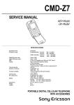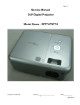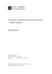
1
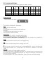
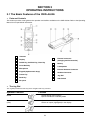
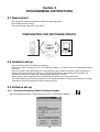
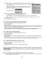
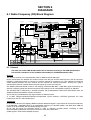
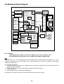
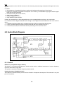
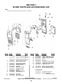
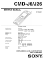
CMD-J6/J26 SERVICE MANUAL E Model ______________________________________________________________________________________________________________ SPECIFICATIONS Signalling format Frequency range GSM power class DCS power class SIM chip Display Channel spacing Number of channels Frequency stability RF output power Battery life Dimensions Weight Volume Dual-Band E-GSM 900 MHz, Transmit: 880 ~ 915 MHz Receive: 925 ~ 960 MHz DCS 1800 MHz, Transmit: 1710 ~ 1785 MHz Receive: 1805 ~ 1880 MHz Class 4 (2W) Class 1 (1W) 3V and 5V Pluggable mini SIM card High resolution full graphics display 4 Grey-scale type Resolution: 96 x 92 pixels 9 lines, proportional font 200 kHz E-GSM: 174 DCS: 374 Transmit frequency drift (synchronized) < ± 0,1 p.p.m GSM: 2W DCS : 1W Standby : 30h -150h standard battery 41h -206h extended battery Talk time : 2h15 - 6h standard battery 3h00 - 8h extended battery 123 mm x 42 mm x 15 mm³ 82 g 79 cm³ PORTABLE DIGITAL CELLULAR TELEPHONE WITH ACCESSORIES Power requirements Operating temperature Accessories operating temperature Connectors WAP (CMD-J6 only) Email Supplied accessories Optional accessories 3.7 V (nominal) -10°C to +55°C ± 0°C to +45°C External RF connector Bottom Connector (12-pin flat I/O connector) Mini plug head set jack Supported protocols by the WAP v.1.1 compliant browser: Wireless Session Protocol (WSP) Wireless Caching Model Wireless Transaction Protocol (WTP) Wireless Control Message Protocol (WCMP) Wireless Markup Language (WML) Wireless Markup Language Script (WMLS) Wireless Bitmap (WBMP) Wireless Transport Layer Security (WTLS Class1) Wireless Telephony Application Interface (WTAI) Supported by the e-mail protocols: SMTP POP 3 AC Adapter Battery (std.) QN-J6BPS Battery (extd.) QN-J6BPE HFK Main Unit QN-3HFK HFK Cradle QN-J5CH Cigar Lighter Charger QN-3CC Data Cable RS QN-3RS Data Cable USB QN-3USB Mobile Data Software QN-3DS Headset QN-3HS Travel Charger QN-3TC NOTE This device contains electrostatically sensitive components. Damage can occur to these components if the appropriate handling is not adhered to. ESD Handling precautions: A working area in which Digital Cellular Telephones may be safely handled without undue risk of damage from electrostatic discharge must be available. The area must be equipped as follows: All working surfaces must have a dissipative bench mat, safe for use with live equipment, connected via 1.2MΩ resistor to a common ground point. ! A quick release skin contact device with a flexible cord, which has a built-in safety resistor of a range between 5.2KΩ and 1.2MΩ shall be used. The flexible cord must be attached to a dissipative earth point. ! All containers and storage must be of the conductive type. ! 2 TABLE OF CONTENTS SECTION 1 Specifications (see Cover sheet) SECTION 2 General Descriptions 2.1 Multi Band . 04 2.2 Radio Frequency Power Level .. 05 2.3 Speech Codec . 05 2.4 Languages . 05 2.5 Battery Charging .. 06 2.6 Battery Safety 06 2.7 Battery Capacity . .. 06 2.8 Accessory Interface .. ... 07 SECTION 3 Operating Instructions 3.1 Basic Features .. 08 3.2 Security Codes .. 09 3.3 Icon Glossary 10 3.4 Menu Overview . 10 SECTION 4 Disassembling/Testing 4.1 Disassembly .. 11-12 4.2 Interface to GSM-Tester .. 13 4.3 Jigs and Tools 14 SECTION 5 Programming Instructions 5.1 Requirement .. 15 5.2 Hardware Set-up .. ... . 15 5.3 Software Set-up . ... 15 5.3.1 Software Download to Mobile . 15-16 5.3.2 Save Personal Data in Mobile . 16 5.3.3 Reset of Personal Data 16 5.3.4 Reset of Security Lock . 16 SECTION 6 Diagrams 6.1 Block Diagram Radio Frequency . .. 17 6.1.1 General RF Indications .. .. 17 6.2 Block Diagram Baseband 18 6.2 1 General Baseband Indications ... 18 6.3 Block Diagram Audio 19 6.3.1 General Audio Indications 19 SECTION 7 Explosion View 7.1 Spare Parts and Accessories List .. 20 3 SECTION 2 GENERAL DESCRIPTIONS 2.1 Multi-band : CMD-J6/J26 support E-GSM 900 and DCS 1800 multi-band functionality. For the use in Europe and in other countries worldwide, ETSI has specified GSM standards into two frequency bands. That is the 900-MHz and 1800-MHz band and is usually referred to as GSM900 and GSM1800 (formerly DCS1800). While the 900-MHz band has 124 channels (extended version: 175), the 1800-MHz band with its 375 channels provides a three-times higher capacity. Not only as a result of this large range of channels but also due to the low transmission power and the transmission distance, GSM1800 supports a higher quantity of RF-channels. The Dual band technology enables a network operator with spectrum at both 900MHz and 1800MHz to support the seamless use of dual band handsets across both frequencies. By supporting seamless handovers between 900MHz and 1800MHz, Dual band networks can provide major benefits in terms of capacity enhancement and revenue optimisation through the introduction of new services. The CMD-J6/J26 is a phase II, GSM 900 class 4, DCS 1800 class 1 mobile phone. The nominal maximum output power for GSM 900 is 2W, for DCS 1800 1W. It supports the extra functionality required for multi-band mobile stations: Inter-band/seamless hand-over, channel assignment, cell selection and re-selection, all between both bands within a Public Land Mobile Network. The manual and automatic PLMN selection in both bands is given. The user does not need any special action to use the multi-band functionality of the phone. Users are able to manually roam between PLMNs operating in GSM 900 and DCS 1800 bands. E-GSM With the further development of the GSM standard, an additional range of frequencies has been made available to the Global system for mobile communications. For each of the two duplex frequency ranges, one for the forward direction and one for the reverse direction, additional 10 MHz have been added to the bottom end of the bands, extending the frequency range to 50 further channels. The mobile station transmits in the 880- to 915 MHz range, and the base station transmits in the 925- to 960 MHz range. A duplex spacing of 45 MHz is used, the base station always transmits on the high side of the duplex frequency pair. The numbering for these additional channels is from 974 to 1023. This is done to avoid assigning one channel number twice within the same standard. Compared to the primary GSM system, Channel number 0 is used in the extended GSM system, since it does not make sense to reserve it at a guard band within the E-GSM bands. Now, the lowest channel, number 974 (880.0 MHz), serves as the guard band between GSM and other services on lower frequencies. DCS 1800 DCS-1800 uses the frequency ranges of 1710 to 1785 MHz in the uplink direction, and 1805 to 1880 MHz in the downlink direction. From these figures it follows that the duplex spacing is 95 MHz with 374 channels with bandwidths of 200 kHz each. The channels are numbered from 512 to 885 in order to distinguish them from the channels in the primary and extended GSM frequency bands. 4 2.2 Radio Frequency Power Levels: Between the DCS 1800 and both GSM Systems are differences regarding the power level. DCS 1800 basically needs lower power levels. If the performance of a MS for GSM system was certified of 2W (Power Class 4), then in the DCS-1800 system it is only 1W (Power Class 1). There are also reduced BTS power levels due to microcell applications, which means instead of the 40W (Power Class 4) in the GSM system DCS 1800 needs only 20W (Power Class 1). Preferences GSM 900 E-GSM DCS 1800 Frequency band uplink: downlink: MHz 890 - 915 935 - 960 MHz 880 - 915 925 - 960 MHz 1710 -1785 1805 - 1880 Radio Channels 124 174 374 max. BS-Power 40 W (46 dBm) 20W (43 dBm) max. MS-Power 2 W (33 dBm) 1W (30 dBm) 2.3 Speech Codec The CMD-J6/J26 supports the following speech codecs. • • • Full Rate (FR) Codec Half Rate (HR) Codec Enhanced Full Rate (EFR) Codec The speech codec forms the human voice into a digital signal, which is sent in the GSM network. The GSM system currently has three different speech codec standards. At first, the Full Rate (FR) Codec was introduced. With new requirements concerning speech quality and availability of radio channel resources two further standards were introduced, the Half Rate (HR) Codec and the Enhanced Full Rate (EFR) Codec. The Half Rate (HR) Codec requires only half the channel capacity of a Full Rate (FR) Channel. The Enhanced Full Rate (EFR) Codec requires the same radio channel resources as a Full Rate (FR) Codec but offers Fixed Line quality with superior vocal clarity. 2.4 Languages The CMD-J6 supports the following languages: • • • • • • • Bulgarian Croatian Czech Danish Dutch English Finnish • • • • • • • French German Greek Hungarian Italian Norwegian Polish • • • • • • • Portugese Romanian Russian Slovakian Spanish Swedish Turkish The CMD-J26 supports the following languages: Taiwan • English Hong Kong • English • Chinese Simplified • Chinese Traditional (for Taiwan) • Chinese Simplified • Chinese Traditional 5 2.5 Battery Charging There is no charging circuitry in the battery pack. The CMD-J6/J26 has complete charger function internally. The telephone can be charged only with the battery connected the phone. This situation can be sub-divided into two situations: the phone is on or off. It can be charged with the AC Adapter, Travel Charger or Cigar Lighter Charger. The battery symbol is used to indicate the charging, and to indicate when the battery is fully charged. This is done using the following sequence of icons: The uncharged segments of the battery are moving in a right to left manner until the charging stops. The sequences for each charging level is repeated until the battery is charged to that level. When the charging sequence is finished the flashing of the battery level sign stops. The phone shows the full-battery icon. 2.6 Battery Safety The battery pack contains a single Li-ion cell, a safety circuitry and, in addition, a microprocessor unit which manages RTC information by reading out the binary counter value in the microprocessor. The charging circuitry and the safety circuitry together guarantee a double fail-safe battery pack. This means that each component can be either short or open and still all the safety requirements will not be violated. The safety concept protects against: Over voltage: The charging is stopped when Battery Voltage (Vbat) reaches 4.25V- 4.3V. The charging resumes when Vbat falls below (4.025V - 4.125V). Under voltage: When the cell voltage drops below 2.242V 2.358V the cell is disconnected for discharging. Charging is still possible. Current fuse: Finally, if all protection functions are out of order due to abnormal condition, the current fuse protects the device from explosion and fire with melting. The fuse melts 10A during 1 second. 2.7 Battery Capacity Standard Battery 640mAh typical Li-ion QN-J6BPS Extended Battery 920mAh typical Li-ion QN-J6BPE The phone can be charged even during making phone calls. However, the shortest charging time will be reached when the phone is switched off. 6 2.8 Accessory interface The table explains what kind of pins the phone supplies to the different accessories. Pins GND Charge GEN Power RX TX Audio Audio I/O OUT (IN) (OUT) ACC RS232 RS232 ID RTS CTS Out IN 3 4 5 6 7 8 9 10 11 12 √ √ √ 1 2 Charger √ CLC √ √ √ HFK √ √ Data Cable RS √ √ √ √ √ √ √ √ Data Cable USB √ √ √ √ √ √ √ √ √ √ AGND Connector layout Connector view from base of phone 12 1 The connector comprises the following pins: Audio Audio In, Audio Out and Audio GND: Audio IN: Is a single ended input with a maximum sensitivity of 365 mVrms. Audio OUT: The single ended output delivers 0.8Vpp into a 1kΩ load. These two signals are referred to as AGND. RS232 Interface 5-pin interface: RX, TX, RTS(RFR), CTS and Gen I/O(DTR or DCD): This is the communication interface to the Data cable QN-3RS/USB. Pin 3 is connected to a general IO pin on the baseband digital chip. The functionality can be assigned on an accessory by accessory basis to be input, output or interrupt. Charge The Charge pin represents the positive contact for the charging funtionality. GND The Ground pin represents the digital interface and charger return current. ID This pin shows the presence of an accessory and is also an analog ID for the accessory. Accessories which provide charger functionality only do not support this pin and their presence is detected with a valid charger voltage. Power Out Power-out has a different functionality with different accessories. In the car-kit environment the ext. Vbat indicates that a phone call is accepted/in progress. This information is used by the car-kit to power up the audio section of the car-kit, mute the car stereo and keep the car-kit powered up even when the ignition is switched off. Due to the fact that the ID of the accessory is detected first, the ACC power is not current limited (protected). 7 SECTION 3 OPERATING INSTRUCTIONS 3.1 The Basic Features of the CMD-J6/J26 • Parts and Controls This section provides a brief guide to the operation and facilities available on the CMD-J6/J26. Refer to the Operating Manual for full operational information. 1 Antenna 2 Display 3 On/Off Key, Call End Key, Clear Key 4 Voice Mail Key 5 Microphone 6 Keypad (alphanumeric keys) 7 Centre Key 8 Send Key 9 Ear piece 10 External connector (Charging and Accessories) 11 Battery 12 Loudspeaker 13 External Antenna Connector 14 Headset Connector 15 Jog Dial 16 Side Switch • The Jog Dial The Jog Dial provides fast and easy menu navigation with only one hand. Operation Function Function Rotate Scrolls through menu options. Opens Phonebook in Standby Mode Press (click) Opens Menu in Standby Mode. Selects an option (highlighted) in the display. Press and Hold Dials the phone number selected. 8 • The Centre Key # Press the Centre Key in standby mode to access the WAP mode if WAP settings are configured. (CMD-J6 only) # During a call, press the Centre Key to access the Call Menu. # In Sub-menus, access/exit the help function by pressing the Centre Key • The Voicemail Key # Press and hold to access your Voicemail • The Side Switch # In standby mode, slide the switch up to activate/deactivate the manner modes. # Afterwards, it is possible to switch among the manner mode functions. All manner mode icons appear in the display; rotate the Jog Dial to select one: Silent Mode :turns the ringer and all tones to silent mode. Ringer to Single beep Vibra Alert :ringer is restricted to a discrete single beep. :Vibra Alert without the ringer. # For your convenience, sliding the side switch up in standby mode will toggle between the two last settings. # In standby mode, slide the switch down to lock/unlock your keypad (including Jog Dial). It is still possible to make emergency calls (112) as well as answer/reject an incoming call (by pressing / ) when the keypad is locked. # During a call, turn the loudspeaker on by sliding the switch up once. Turn the loudspeaker off by sliding the switch up again. # During an incoming call, stop the ringer by sliding the side switch up. # During a game, stop/start the backround sound by sliding the side switch up. 3.2 Security Codes CODE TYPE NUMBER OF DIGITS DESCRIPTION PIN Personal Identification Number 4 to 8 Controls SIM security. Supplied by the Service Provider ! PIN 2 4 to 8 Controls memory security. Supplied by the Service Provider ! 8 Used to unblock PIN and PIN 2. A PIN or PIN 2 will become blocked if the wrong PIN or PIN 2 is entered three times. When the blocked PIN or PIN 2 is unblocked, a new PIN or PIN 2 must be entered. If the wrong PUK or PUK 2 is entered 10 times, the SIM card will be unusable. Supplied by the Service Provider ! Bearing Password 4 Controls the call bar function. If the wrong password is entered three times, this service will be revoked. Supplied by the Service Provider ! Security Code 4 to 8 Controls the access to wap-and e-mail settings. The default Security Code is: 0000 Refer to Section 5 Programming Instructions PIN / PIN 2 Personal Unblocking Key (PUK / PUK 2) 9 3.3 Icon Glossary ICON Explanation ICON Explanation Network not available Missed calls Network signal strenght (strong) Incoming call barring Battery strength Outgoing call barring SMS (Envelope Icon) Incoming + Outgoing call barring Voicemail Conditional Divert Keypad locked Unconditional Divert Alarm Active call Silent Mode Call hold Vibra Alert Mute Microphone Single Beep Headset connected Ringer off Handsfree Kit connected Conversation Privacy (ciphering) not supportet Loudspeaker on 3.4 Menu Overview Press the Jog Dial from standby mode to acess the Main menu: CMD-J6 only Read message Create message Settings Local area info Browser Favourites Settings Ringer Set Sound Calendar Preferences Security Call data Call settings If not reachable If no reply If busy All calls All fax All data Cancel all Clock Calculator Games E-mail Incomming Calls Outgoing Calls Missed Calls Delete All Phonebook menu Voicemail Search 10 SECTION 4 DISASSEMBLY IMPORTANT NOTE : The IMEI number is the electronic identification of the hardware, which is stored electronically. There should be no discrepancy between the number on the sticker and the number within the set memory allowed. In case of replacing the lower cabinet it is to make sure that the IMEI Sticker mounted on the lower case (visible from the battery compartment) will be replaced to the new housing part as well. Follow the disassembly procedure in the numerical order given. CABINET UPPER MAIN BOARD ASSY 11 LCD IMPORTANT: Do not detach the shield case from the main board CABINET LOWER Re-assembly procedure : To re-assemble the unit, apply the reverse order of the above mention disassembly procedure. 12 4.2 Interface to GSM-Tester Test Set Up for CMD-J6/J26 Level 1 Testing CMD- J 6/J 26 + Battery Pack + Test SIM Card Service Test Connector RF output : SMA jack* STC-03 Part No. 3-224-391-01 RF input Connector * GSM TESTER This unit acts as a base station providing all the necessary GSM signalling requirements and provides GSM signal measuring facilities as well. * Use special RF-Adapter for connection of STC-03 to your GSM Tester ! 13 Level Test Procedure with GSM TESTER recommendation: • • Simulate GSM call processing to check the functionality of transmitting and receiving audio signals of loudspeaker and microphone. Basic GSM transmission & reception parameter testing to ensure that handsets performance compiles with standard GSM specification. 4.3 Jigs & Tools Description DATA TRANSFER CABLE DTC-04 HOOK RELEASE JIG SERVICE TEST CONNECTOR STC-03 Part No Remark 1-757-348-11 Necessary For Software Update 3-043 180 01 For Housing Opening 3-224 391-01 For Connection To GSM Measure Equipment HOOK RELEASE JIG DATA TRANSFER CABLE SERVICE TEST CONNECTOR 14 Section 5 PROGRAMMING INSTRUCTIONS 5.1 Requirement • PC (486 type or higher) with Microsoft Windows Operating System • One COM-port free for usage • The Data Transfer Cable (p/n 1-757-348-11) PREPARATION FOR SOFTWARE UPDATE DATA TRANSFER CABLE 5.2 Hardware set-up • Copy all the files to the PC (define own directory). • Connect the Data Transfer Jig to the PC COM-port (COM 1 or COM 2) and the CMD-J6/J26 external connector. • Insert a test SIM in the CMD-J6/J26; this is because during the procedure the Flash Loader will attempt to perform data control operations, which are not generally permitted by original SIMs. The test SIM is not absolutely necessary for a generally software update, although it is useful. • Attach battery pack to CMD-J6/J26; the CMD-J6/J26 is powered up from the battery pack. • The initial settings of the flash.exe program may not correspond with the normally correct settings. It is highly advisable to check the settings first (see 5.3 Software set-up). 5.3 Software set-up 5.3.1 ∗ Download Software to Mobile (Software Update) • Start the program flash.exe by double-clicking on its icon in the Windows Explorer. 15 flash 437.exe • Select file/Settings and check if the settings for the Com Portand Speed are correct. − The FlashLoader automatically detects all available Com ports on the PC. (COM 1 or COM 2) − Baud rates up to 812500bps will be supported, but standard PCs, unless it is correctly customised (i.e. with a Fast Serial Board), will not support Baud rates > 115200bps. − The default values are COM1 115200 • Click on the Load button and select an SRE file for downloading. − The CMD-J26 software is located in the xx437.SRE file. − Any other SRE file is either only needed for the program itself, or can be a personal data file. Note: If a flash.sre file appears, please mind that this is application software (do not use / modify) • Switch on the CMD-J26. • Now the program runs automatically. 5.3.2 ∗ Save User Data in Mobile (Get Data / Write Data) • • • • • Check if the settings for the Com Port and Speed are correct. Switch on the CMD-J26. Click on Get Data. Now the program runs automatically (if the application does not start after a while, press any key of the CMD-J26) After the read data is downloaded, either reload it in another mobile (reconnect a new mobile and click on Write Data) or save it on the disc using File/Save option. • When the message write user data complete appears, disconnect the Data Transfer Cable and make sure that the attached battery pack will be removed (do not switch off the terminal with the ON/OFF key). 5.3.3 ∗ Reset of User Data (Erase Data) • • • • Check if the settings for the Com Port and Speed are correct. Switch on the CMD-J26. Click on Erase Data. Now the program runs automatically, all individual settings (such as Phonebook entries and WAP settings etc.) will be deleted. • When the message erase user data complete appears, disconnect the Data Transfer Cable and make sure that the attached battery pack will be removed (do not switch off the terminal with the ON/OFF key). 5.3.4 ∗ Reset of Security Code Lock (Clear Lock) • Check if the settings for the Com Port and Speed are correct. • Switch on the CMD-J26. • Click on Clear Lock. • The individual Security Code will be reset to the default setting: 0000 ! For any of the above stated functions, follow the instructions written in the status bar (the first one from the top). Follow up the progress of the up/download process by checking the Progress bar (the second one from the top). Note: Do not forget to remove the test SIM before returning an intact mobile phone. With the SIM in the phone the customer will no longer be able to check into a radio network; so even though the phone is intact, it will be of no use to the customer. 16 SECTION 6 DIAGRAMS 6.1 Radio Frequency (RF) Block Diagram VCC_RF LDO VCC_SYNTH LDO RF_EN Rx frontend filter DCS Rx interstage filter 1st Rx mixer LNA RF Ceramic Filter 1805..1880 MHz IF SAW Filter 1805..1880 MHz IQ Demodulator IF SAW Filter 440 MHz LO RXIN BB amplifier and low pass filter 90° ∑ 0 ° LNA GSM RXIP I IF Amplifier (PGC) RXQP RXQN Q RF SAW Filter 925..960 MHz IF SAW Filter 925..960 MHz LO RX: GSM 1365..1400 MHz DCS 1365..1440 MHz AFC VCTCXO CLK13M 13 MHz 440 MHz RX LO1 (RF) PLL: - RX GSM 1365..1400 MHz DCS 1365..1440 MHz - TX GSM 1370..1440 MHz DCS 1385..1460 MHz 1 LNA Bias control 2 Transceiver 880 MHz Antenna Antenna Switch 1 GSM 880..915 MHz Pin diode switch Tx GSM VCO 880..915 MHz 5 1 1 Down Converter DCS1800 1710..1785 MHz Pin diode switch LP Filter IC 2 DET_EN DET_TX TXP_OFS_EN Analog signals AUX_DAC LO2 (IF) PLL 1 MHz step SERCK SERDA SERLE2 Sum loop I ϕ ∑ Phase detector Digital signals 1 GSM :5 DCS :3 LP Filter TX_SW_EN GSM_TX_EN GSM_VCO_EN APC_DOWN DCS_TX_EN DCS_VCO_EN TXIP 90° 0 ° TXIN TXQP GSM 195 MHz DCS 325 MHz IC 1 M N 1 SERLE1 Tx DCS VCO 1710..1785 MHz Loop Filter PA Loop Filter Total VCO Range: 880 to 975 MHz LP Filter PA Directional coupler LO2 VCO GSM TX: GSM 685..720 MHz DCS 1385..1460 MHz 3/5 Directional coupler + LPF ϕ 2 DCS 1 PLL LO2 (IF) PLL RX 880 MHz TX 975 MHz Detector and Level control N Loop Filter TX: GSM 1370..1440 MHz DCS 1385..1460 MHz TX 975 MHz APC loop 1 ϕ LO1 VCO RF Connector with mechanical switch LO1 (RF) PLL 200 kHz step N N+1 Total VCO Range: 1365 to 1460 MHz Q TXQN RF_IC_EN TXP 6.1.1 General The radio part of the CMD-J6/J26 handles the air interface according to the GSM specifications. It is the main contributor for the dualband functionality for E-GSM 900 and DCS 1800. Receiver The receiver consists of two separated RF paths for GSM and DCS 1800 each. On the transmission line between the antenna switch of the RF part and the antenna there is the RF connector including a mechanical switch to connect an external antenna for accessory use. The integrated mechanical switch switches between the helix antenna and the external RF antenna connection. As long as a plug is connected the antenna is deactivated and all RF signals go across the connector. The GMSK (Gaussian-filtered minimum shift keying) modulated 900 MHz / 1800 MHz signal received by the antenna is filtered, gained and downconverted into the baseband via an intermediate frequency of 440 MHz. The 440 MHz filter is followed by a tuneable amplifier and IQ demodulator. Behind the demodulator there are additional base band amplifiers and low pass filters. The In Phase (I) and Quadrature (Q) signal outputs are balanced each. A 13 MHz voltage-controlled-temperature-compensated crystal oscillator (VCTCXO) generates the clock frequency for the PLL and baseband part. Transmitter In the transmit direction the digitally GMSK-modulated baseband signal is upconverted to the transmit frequency in the 900 MHz / 1800 MHz band via an intermediate frequency of 195 MHz (GSM) / 325 MHz (DCS 1800) by means of an IQ modulator and the subsequenting sum loop. All RF and IQ signals are balanced signals in order to suppress crosstalk effects. According to GSM recommendations transmitter and receiver are never active at the same time. (TDMA system Time Division Multiple Access). 17 6.2 Baseband Block Diagram KEY-LED BL-I/F MCP-I/F FLASH/SRAM LCD-LED KEY-I/F LCD-I/F KEY-MATRIX FLEX-BOARD LCD IC 1 I/O CONNECTOR SLIDE-SW (REC/LOCK or Manner) JOG DIAL 1 DGND 2 3 4 5 6 CHG GEN I/O POWER OUT RX (IN) TX (OUT) 7 8 9 ACC ID RTS CTS RTC 10 AUDIO OUT 11 AUDIO IN 12 AGND SIM Interface Battery Connector KEYBOARD MODEM-I/F TIME PROCCESSING UNIT Power / CHG Management LI-ION BATTERY SIM I/F RTC / ID HFK I/F SIM Connector SIM LEVEL CTRL 3V/5V A/D CONV JOG JOG-I/F Multiactor RINGER AUDIO AMP 32kHz CLKCTRL HEADSET AUDIO & REMOTE RF-I/F IC 2 I/F *Ringer *Vibrator *LoudSpeaker HEADPHONE-JACK MIC IC 1 I/F AUDIO AMP AUDIO I/F IC 2 EAR RECEIVER MIC RF I/F A/D, D/A SIM CARD RF BLOCK TCXO 6.2.1 General The Baseband part consists of two chips, a digital chip IC 1 and an analog one IC 2. The CMD-J6/J26 external memory size is 32 Mbits Flash ROM and 4 Mbit SRAM. IC 1 The application of IC 1 is the management of the GSM baseband processes through the GSM layer 1, 2 and 3 protocols as described in the ETSI standard with a specific attention to the power consumption in both GSM dedicated and idle modes. It is a chip that implements: ! the digital baseband processes of the CMD-J6/J26 and combines a Digital Signal Processing (DSP) with its program and data memories, ! a Micro-Controller core with emulation facilities and an internal RAM memory, ! a clock squarer cell, ! several compiled ports and equivalent CMOS gates. Full support for Full-Rate, Enhanced Full-Rate and Half-Rate speech coding is given. 18 IC 2 IC 2 is the platform of the A/D-D/A converter for the interfacing and processing of baseband I/Q signals and voice signals. It includes: ! the complete set of baseband functions to perform the interface and processing of voice signals, ! interface for processing of baseband components as In Phase (I) and Quadrature (Q) signals which support single slot and multi slot mode, ! associated auxiliary RF control features, ! supply voltage regulation, ! battery charging control and ! switch ON/OFF system analysis. Further, IC 2 includes also on chip voltage reference, under voltage detection and power -on reset circuits. IC 2 interfaces with the digital baseband device through a set of digital interfaces dedicated to the main functions of IC 1: 1. A baseband serial port (BSP) and a voiceband serial port (VSP) to communicate with the DSP. 2. A micro- controller serial port (USP) to communicate with the micro contoller core of IC 1. 3. A time serial port (TSP) to communicate with the processing unit for real time control. 6.3 Audio Block Diagram IC 1 IC 2 6.3.1 General Multiactor (Loudspeaker /Ringer Vibrator) This device is a combined electrodynamic vibration exciter with an additional membrane to improve frequency response and enhance ringer level. The system is tuned to the vibration frequency around 130 Hz. Headset Connector (Headphone Jack) The headset is connected directly to the circuit to the built in microphone and earpiece. The connector is a 4-pole jack with 2 switches. 19 SECTION 7 SPARE PARTS AND ACCESSORIES LIST Note: • The parts with no reference in the exploded view are not supplied. Ref. No. Part No. Description Remark 2 2 A-3649-310-A CABINET UPPER SUB-ASSY (SILVER) A-3649-368-A CABINET UPPER SUB-ASSY (WHITE) A-3649-372-A CABINET UPPER SUB-ASSY (BLUE) 3-232-307-11 BADGE, PRINTING (SILVER) 3-235-856-01 BADGE, PRINTING (WHITE) 2 3 4 5 6 3-235-856-11 1-542-441-21 3-228-345-01 1-251-898-41 3-228-337-01 BADGE, PRINTING (BLUE) MICROPHONE (ASSEMBLY) GROMET SPEAKER RECEIVER RUBBER KEY (SILVER) 6 6 7 8 9 3-228-337-11 3-228-337-21 A-3649-308-A 1-794-665-11 1-793-605-22 RUBBER KEY (WHITE) RUBBER KEY (BLUE) LCD ASSY CONNECTOR HOUSING SIM CONNECTOR 1 1 1 10 11 12 Ref. No. Description Remark 13 14 14 14 15 1-529-799-21 X-3380-306-2 X-3381-222-1 X-3381-223-1 3-228-343-01 MULTIACTOR CABINET LOWER ASSY (SILVER) CABINET LOWER ASSY (WHITE) CABINET LOWER ASSY (BLUE) CAP, RF 16 17 17 17 18 3-228-342-01 1-756-202-11 1-756-202-21 1-756-202-31 3-929-548-01 CAP, JACK LI-ION BATTERY (PACK) (SILVER) LI-ION BATTERY (PACK) (WHITE) LI-ION BATTERY (PACK) (BLUE) SCREW (1.7X6), +PTT 19 20 20 3-224-788-01 1-754-151-21 1-754-151-41 SCREW (DIA. 1.4X4.5), PRECISION HELICAL ANTENNA (SILVER) HELICAL ANTENNA (WHITE, BLUE) ACCESSORIES ****************** 1-476-205-13 3-232-308-21 A-3622-529-A FLEX MOUNT 3-228-344-01 PLATE, JACK 1-418-426-21 ROTARY ENCORDER 9-873-708-21 Part No. Sony Corporation Digital Telecommunications Network Company 20 AC ADAPER EU (QN-3AC8) INSTRUCTION MANUAL (CHINESE, SIMPLEFIED) © 2001.8 Published by Quality Assurance Dept.