1
Motion Control Engineering, Inc.
11380 White Rock Road
Rancho Cordova, CA 95742
voice 916 463 9200
fax 916 463 9201
www.mceinc.com
Tricon Controller, Installation & Adjustment:
Magnetek HPV 600 Drive
Magnetek HPV 900 Drive
Yaskawa F7 Drive
Mitsubishi A500 Drive
Magnetek DSD 412 DC Drive
V6.2x Software
Manual # 42-02-2T00, Rev F4, October 2009
Copyright
© 2009, Motion Control Engineering. All Rights Reserved.
This document may not be reproduced, electronically or mechanically, in whole or in part, without
written permission from Motion Control Engineering.
Trademarks
All trademarks or registered product names appearing in this document are the exclusive property
of the respective owners.
Warning and Disclaimer
Although every effort has been made to make this document as complete and accurate as possible,
Motion Control Engineering and the document authors, publishers, distributors, and
representatives have neither liability nor responsibility for any loss or damage arising from
information contained in this document or from informational errors or omissions. Information
contained in this document shall not be deemed to constitute a commitment to provide service,
equipment, or software by Motion Control Engineering or the document authors, publishers,
distributors, or representatives.
Limited Warranty
Motion Control Engineering (manufacturer) warrants its products for a period of 15 months from
the date of shipment from its factory to be free from defects in workmanship and materials. Any
defect appearing more than 15 months from the date of shipment from the factory shall be
deemed to be due to ordinary wear and tear. Manufacturer, however, assumes no risk or liability
for results of the use of the products purchased from it, including, but without limiting the
generality of the forgoing: (1) The use in combination with any electrical or electronic components,
circuits, systems, assemblies or any other material or equipment (2) Unsuitability of this product
for use in any circuit, assembly or environment. Purchasers’ rights under this warranty shall
consist solely of requiring the manufacturer to repair, or in manufacturer's sole discretion, replace
free of charge, F.O.B. factory, any defective items received at said factory within the said 15
months and determined by manufacturer to be defective. The giving of or failure to give any advice
or recommendation by manufacturer shall not constitute any warranty by or impose any liability
upon the manufacturer. This warranty constitutes the sole and exclusive remedy of the purchaser
and the exclusive liability of the manufacturer, AND IN LIEU OF ANY AND ALL OTHER
WARRANTIES, EXPRESSED, IMPLIED, OR STATUTORY AS TO MERCHANTABILITY, FITNESS, FOR
PURPOSE SOLD, DESCRIPTION, QUALITY PRODUCTIVENESS OR ANY OTHER MATTER. In no event
will the manufacturer be liable for special or consequential damages or for delay in performance of
this warranty.
Products that are not manufactured by MCE (such as drives, CRTs, modems, printers, etc.) are not
covered under the above warranty terms. MCE, however, extends the same warranty terms that
the original manufacturer of such equipment provide with their product (refer to the warranty
terms for such products in their respective manual).
End User License Agreement
This End User License Agreement (“Agreement”) grants you the right to use the software contained in this product (the “Software”) subject to the following restrictions: You may not: (i) copy
the Software, except for archive purposes consistent with your standard archive procedures; (ii)
transfer the Software to a third party apart from the entire product; (iii) modify, decompile, disassemble, reverse engineer or otherwise attempt to derive the source code of the Software; (iv)
export the Software or underlying technology in contravention of applicable U.S. and foreign
export laws and regulations; and (v) use the Software other than in connection with operation of
the product.
“LICENSOR'S SUPPLIERS DO NOT MAKE OR PASS ON TO END USER OR ANY OTHER THIRD PARTY,
ANY EXPRESS, IMPLIED OR STATUTORY WARRANTY OR REPRESENTATION ON BEHALF OF SUCH
SUPPLIERS, INCLUDING BUT NOT LIMITED TO THE IMPLIED WARRANTIES OF NON-INFRINGEMENT, TITLE, MERCHANTABILITY OR FITNESS FOR A PARTICULAR PURPOSE.”
Important Precautions and Useful Information
This preface contains information that will help you understand and safely maintain MCE
equipment. We strongly recommend you review this preface and read this manual before
installing, adjusting, or maintaining Motion Control Engineering equipment. This preface discusses:
•
•
•
•
Safety and Other Symbol Meanings
Safety Precautions
Environmental Considerations
In This Guide
Safety and Other Symbol Meanings
Danger
This manual symbol is used to alert you to procedures, instructions, or situations which, if not done
properly, might result in personal injury or substantial equipment damage.
Caution
This manual symbol is used to alert you to procedures, instructions, or situations which, if not done
properly, might result in equipment damage.
Note
This manual symbol is used to alert you to instructions or other immediately helpful information.
Safety Precautions
Danger
This equipment is designed to comply with ASME A17.1, National Electrical Code, CE, and CAN/
CSA-B44.1/ASME-A17.5 and must be installed by a qualified contractor. It is the responsibility of the
contractor to make sure that the final installation complies with all local codes and is installed in a
safe manner.
This equipment is suitable for use on a circuit capable of delivering not more than 10,000 rms symmetrical amperes, 600 volts maximum. The three-phase AC power supply to the Drive Isolation
Transformer used with this equipment must originate from a fused disconnect switch or circuit
breaker sized in conformance to all applicable national, state, and local electrical codes in order to
provide the necessary motor branch circuit protection for the Drive Unit and motor. Incorrect motor
branch circuit protection will void the warranty and may create a hazardous condition.
Proper grounding is vitally important to safe and successful operation. Bring your ground wire to the
system subplate. You must choose the proper conductor size and minimize the resistance to ground
by using the shortest possible routing. See National Electrical Code Article 250-95 or the applicable
local electrical code.
Before applying power to the controller, physically check all the power resistors and other components located in the resistor cabinet and inside the controller. Components loosened during shipment may cause damage.
For proper operation of the AC Drive Unit in your controller, you must make sure that: 1) A direct
solid ground is provided in the machine room to properly ground the controller and motor. Indirect
grounds such as the building structure or a water pipe may not provide proper grounding and could
act as an antenna to radiate RFI noise, thus disturbing sensitive equipment in the building. Improper
grounding may also render any RFI filter ineffective. 2) The incoming power to the controller and the
outgoing power wires to the motor are in their respective, separate, grounded conduits.
This equipment may contain voltages as high as 1000 volts. Use extreme caution. Do not touch any
components, resistors, circuit boards, power devices, or electrical connections without ensuring that
high voltage is not present.
Environmental Considerations
•
•
•
•
•
•
•
•
Keep the machine room clean.
Controllers are generally in NEMA 1 enclosures.
Do not install the controller in a dusty area.
Do not install the controller in a carpeted area.
Keep room temperature between 32 and 104 degrees F (0 to 40 degrees C).
Prevent condensation on the equipment.
Do not install the controller in a hazardous location or where excessive amounts of
vapors or chemical fumes may be present.
Make certain that power line fluctuations are within plus or minus 10% of proper value.
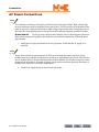
Air Conditioned Equipment Cabinets
If your control or group enclosure is equipped with an air conditioning unit, it is very important
to observe the following precautions. (Failure to do so can result in moisture damage to electrical components.)
•
•
•
•
•
Maintain the integrity of the cabinet by using sealed knockouts and sealing any holes
made during installation.
Do not run the air conditioning while the cabinet doors are open.
If you turn the air conditioner off while it is running, wait at least five minutes before
restarting it. Otherwise, the compressor may be damaged.
Observe the recommended thermostat setting (75 degrees) and follow recommended
maintenance schedules.
Make certain that the air conditioning drain tube remains clear to avoid water accumulation in the unit.
In This Manual:
This manual is the installation, adjustment, and troubleshooting guide for the Tricon car control. When viewed online as a pdf file, hyperlinks (buttons or blue text) link to related topics and
informational websites. The manual includes:
•
•
•
•
•
•
•
Contents: Table of Contents. When viewed online as a pdf file, hyperlinks in the Contents
link to the associated topic in the body of the manual.
Section 1. Tricon General Information: System description; operating modes.
Section 2. Installation.
Section 3. Startup & Drive Adjustment.
Section 4. Release to Normal Operation: Limit board adjustment and Final test descriptions.
Section 5. Tricon Configuration: How to use the Hand Held Unit to program and troubleshoot the controller. Complete with parameter definitions where appropriate.
Index: Alphabetical index to help you find information in the manual. When viewed
online as a pdf file, index entry page references are hyperlinks to the associated information in the body of the manual.
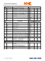
Contents
Section 1. Tricon General Information
Tricon . . . . . . . . . . . . . . . . . . . . . . . . . . . . . . . . . . . . . . . . . . . . . . . . . . . . . . . . . . . . . 1-1
Car Controller . . . . . . . . . . . . . . . . . . . . . . . . . . . . . . . . . . . . . . . . . . . . . . . . . . . . . . 1-2
Controller Circuit Boards . . . . . . . . . . . . . . . . . . . . . . . . . . . . . . . . . . . . . . . . . . . . . . . . . . . . .1-5
Cartop Station . . . . . . . . . . . . . . . . . . . . . . . . . . . . . . . . . . . . . . . . . . . . . . . . . . . . . . 1-9
Cartop Circuit Boards . . . . . . . . . . . . . . . . . . . . . . . . . . . . . . . . . . . . . . . . . . . . . . . . . . . . . . . 1-9
Cartop Junction Box . . . . . . . . . . . . . . . . . . . . . . . . . . . . . . . . . . . . . . . . . . . . . . . . . . . . . . . .1-10
Car Station . . . . . . . . . . . . . . . . . . . . . . . . . . . . . . . . . . . . . . . . . . . . . . . . . . . . . . . 1-10
Dispatcher . . . . . . . . . . . . . . . . . . . . . . . . . . . . . . . . . . . . . . . . . . . . . . . . . . . . . . . . 1-11
Dispatcher Circuit Boards . . . . . . . . . . . . . . . . . . . . . . . . . . . . . . . . . . . . . . . . . . . . . . . . . . . . 1-11
Hand Held Unit (HHU) . . . . . . . . . . . . . . . . . . . . . . . . . . . . . . . . . . . . . . . . . . . . . 1-12
HHU / Dispatcher Board Connection (Optional) . . . . . . . . . . . . . . . . . . . . . . . . . . . . . . . .1-13
Control Parameters . . . . . . . . . . . . . . . . . . . . . . . . . . . . . . . . . . . . . . . . . . . . . . . . 1-13
Operating Modes . . . . . . . . . . . . . . . . . . . . . . . . . . . . . . . . . . . . . . . . . . . . . . . . . . 1-14
Inspection Operation . . . . . . . . . . . . . . . . . . . . . . . . . . . . . . . . . . . . . . . . . . . . . . . . . . . . . . . .1-14
Controller Inspection . . . . . . . . . . . . . . . . . . . . . . . . . . . . . . . . . . . . . . . . . . . . . . . . . . . . 1-14
Car Top Inspection . . . . . . . . . . . . . . . . . . . . . . . . . . . . . . . . . . . . . . . . . . . . . . . . . . . . . . 1-14
Access Inspection. . . . . . . . . . . . . . . . . . . . . . . . . . . . . . . . . . . . . . . . . . . . . . . . . . . . . . . . 1-14
Car Switch Operation . . . . . . . . . . . . . . . . . . . . . . . . . . . . . . . . . . . . . . . . . . . . . . . . . . . . . . . . 1-15
Running the Car From the Hand Held . . . . . . . . . . . . . . . . . . . . . . . . . . . . . . . . . . . . . . 1-15
Setting Up Car Switch Operation . . . . . . . . . . . . . . . . . . . . . . . . . . . . . . . . . . . . . . . . . . . 1-15
Operation . . . . . . . . . . . . . . . . . . . . . . . . . . . . . . . . . . . . . . . . . . . . . . . . . . . . . . . . . . . . . . 1-15
Car Door Operation . . . . . . . . . . . . . . . . . . . . . . . . . . . . . . . . . . . . . . . . . . . . . . . . . . . . . . 1-16
Hall Call Operation . . . . . . . . . . . . . . . . . . . . . . . . . . . . . . . . . . . . . . . . . . . . . . . . . . . . . . 1-16
Emergency Power Operation . . . . . . . . . . . . . . . . . . . . . . . . . . . . . . . . . . . . . . . . . . . . . . . . .1-16
Operation Modes: . . . . . . . . . . . . . . . . . . . . . . . . . . . . . . . . . . . . . . . . . . . . . . . . . . . . . . . 1-16
Software Required . . . . . . . . . . . . . . . . . . . . . . . . . . . . . . . . . . . . . . . . . . . . . . . . . . . . . . . 1-16
Input Mapping . . . . . . . . . . . . . . . . . . . . . . . . . . . . . . . . . . . . . . . . . . . . . . . . . . . . . . . . . . 1-17
Car Parameters Description and Operation . . . . . . . . . . . . . . . . . . . . . . . . . . . . . . . . . . 1-18
Dispatcher Parameters Description and Operation. . . . . . . . . . . . . . . . . . . . . . . . . . . . 1-18
Code Blue Operation . . . . . . . . . . . . . . . . . . . . . . . . . . . . . . . . . . . . . . . . . . . . . . . . . . . . . . . .1-19
Recall Procedure . . . . . . . . . . . . . . . . . . . . . . . . . . . . . . . . . . . . . . . . . . . . . . . . . . . . . . . . 1-19
Car Parameters Description . . . . . . . . . . . . . . . . . . . . . . . . . . . . . . . . . . . . . . . . . . . . . . . 1-19
Dispatcher Parameters Description. . . . . . . . . . . . . . . . . . . . . . . . . . . . . . . . . . . . . . . . . 1-20
Seismic Operation . . . . . . . . . . . . . . . . . . . . . . . . . . . . . . . . . . . . . . . . . . . . . . . . . . . . . . . . . .1-21
Seismic Input and Output Definitions. . . . . . . . . . . . . . . . . . . . . . . . . . . . . . . . . . . . . . . 1-22
i
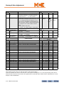
Section 2. Installation
Installation . . . . . . . . . . . . . . . . . . . . . . . . . . . . . . . . . . . . . . . . . . . . . . . . . . . . . . . . 2-1
Install Sequence . . . . . . . . . . . . . . . . . . . . . . . . . . . . . . . . . . . . . . . . . . . . . . . . . . . .2-2
Supporting Information . . . . . . . . . . . . . . . . . . . . . . . . . . . . . . . . . . . . . . . . . . . . . . . . . . . . . 2-2
Safety . . . . . . . . . . . . . . . . . . . . . . . . . . . . . . . . . . . . . . . . . . . . . . . . . . . . . . . . . . . . .2-3
Personal Safety . . . . . . . . . . . . . . . . . . . . . . . . . . . . . . . . . . . . . . . . . . . . . . . . . . . . . . . . . . . . . 2-3
Equipment Safety . . . . . . . . . . . . . . . . . . . . . . . . . . . . . . . . . . . . . . . . . . . . . . . . . . . . . . . . . . . 2-3
Installation Considerations . . . . . . . . . . . . . . . . . . . . . . . . . . . . . . . . . . . . . . . . . .2-4
Machine Room Preparation . . . . . . . . . . . . . . . . . . . . . . . . . . . . . . . . . . . . . . . . . . . . . . . . . . 2-4
Piping and Wiring . . . . . . . . . . . . . . . . . . . . . . . . . . . . . . . . . . . . . . . . . . . . . . . . . . . . . . . . . . 2-5
How Electrical Noise Occurs . . . . . . . . . . . . . . . . . . . . . . . . . . . . . . . . . . . . . . . . . . . . . . . 2-5
How to Avoid Electrical Noise Problems . . . . . . . . . . . . . . . . . . . . . . . . . . . . . . . . . . . . . 2-5
Possible EMI/RFI Interference . . . . . . . . . . . . . . . . . . . . . . . . . . . . . . . . . . . . . . . . . . . . . 2-6
Equipment Grounding . . . . . . . . . . . . . . . . . . . . . . . . . . . . . . . . . . . . . . . . . . . . . . 2-7
Wiring Connections for Properly Grounded Systems . . . . . . . . . . . . . . . . . . . . . . . . . . . . . 2-7
AC Power Connections . . . . . . . . . . . . . . . . . . . . . . . . . . . . . . . . . . . . . . . . . . . . . .2-8
Initial Power Up . . . . . . . . . . . . . . . . . . . . . . . . . . . . . . . . . . . . . . . . . . . . . . . . . . . . . . . . . . . . 2-9
Motor, Brake, and Encoder Connection . . . . . . . . . . . . . . . . . . . . . . . . . . . . . . .2-10
Motor Connection . . . . . . . . . . . . . . . . . . . . . . . . . . . . . . . . . . . . . . . . . . . . . . . . . . . . . . . . . 2-10
Insulation Breakdown Test. . . . . . . . . . . . . . . . . . . . . . . . . . . . . . . . . . . . . . . . . . . . . . . . 2-10
Motor Wiring . . . . . . . . . . . . . . . . . . . . . . . . . . . . . . . . . . . . . . . . . . . . . . . . . . . . . . . . . . . 2-10
Brake Connection . . . . . . . . . . . . . . . . . . . . . . . . . . . . . . . . . . . . . . . . . . . . . . . . . . . . . . . . . . 2-10
Brake Mechanics . . . . . . . . . . . . . . . . . . . . . . . . . . . . . . . . . . . . . . . . . . . . . . . . . . . . . . . . 2-10
Velocity Encoder Installation and Wiring . . . . . . . . . . . . . . . . . . . . . . . . . . . . . . . . . . . . . . .2-11
Encoder Mounting . . . . . . . . . . . . . . . . . . . . . . . . . . . . . . . . . . . . . . . . . . . . . . . . . . . . . . . 2-11
Encoder Isolation. . . . . . . . . . . . . . . . . . . . . . . . . . . . . . . . . . . . . . . . . . . . . . . . . . . . . . . . 2-12
Encoder Wiring . . . . . . . . . . . . . . . . . . . . . . . . . . . . . . . . . . . . . . . . . . . . . . . . . . . . . . . . . 2-12
T-Limit-2K Motor Speed/Position Sensor . . . . . . . . . . . . . . . . . . . . . . . . . . . . . . . . . . . . . 2-13
Mounting the Magnet Assembly . . . . . . . . . . . . . . . . . . . . . . . . . . . . . . . . . . . . . . . . . . . 2-13
Mounting the Speed Sensor . . . . . . . . . . . . . . . . . . . . . . . . . . . . . . . . . . . . . . . . . . . . . . . 2-14
Construction Operation . . . . . . . . . . . . . . . . . . . . . . . . . . . . . . . . . . . . . . . . . . . . 2-15
Minimal Requirements . . . . . . . . . . . . . . . . . . . . . . . . . . . . . . . . . . . . . . . . . . . . . . . . . . . . . 2-15
Jumper Requirements. . . . . . . . . . . . . . . . . . . . . . . . . . . . . . . . . . . . . . . . . . . . . . . . . . . . 2-15
Required Controller and Drive Parameter Settings . . . . . . . . . . . . . . . . . . . . . . . . . . . . . . 2-15
Controller Parameters . . . . . . . . . . . . . . . . . . . . . . . . . . . . . . . . . . . . . . . . . . . . . . . . . . . . 2-16
Drive Parameters . . . . . . . . . . . . . . . . . . . . . . . . . . . . . . . . . . . . . . . . . . . . . . . . . . . . . . . . 2-16
Using Inspection Stations to Run . . . . . . . . . . . . . . . . . . . . . . . . . . . . . . . . . . . . . . . . . . . . . 2-16
Controller . . . . . . . . . . . . . . . . . . . . . . . . . . . . . . . . . . . . . . . . . . . . . . . . . . . . . . . . . . . . . . 2-16
Car Top Inspection . . . . . . . . . . . . . . . . . . . . . . . . . . . . . . . . . . . . . . . . . . . . . . . . . . . . . . 2-16
Temporary Run Box Hookup . . . . . . . . . . . . . . . . . . . . . . . . . . . . . . . . . . . . . . . . . . . . . . . . .2-17
Running the Car . . . . . . . . . . . . . . . . . . . . . . . . . . . . . . . . . . . . . . . . . . . . . . . . . . . . . . . . . . . 2-18
Brake Basics . . . . . . . . . . . . . . . . . . . . . . . . . . . . . . . . . . . . . . . . . . . . . . . . . . . . . . . . . . . . 2-18
ii Manual # 42-02-2T00 F4, 10/6/09
Completing Installation . . . . . . . . . . . . . . . . . . . . . . . . . . . . . . . . . . . . . . . . . . . . 2-19
Low Voltage Signal Wiring . . . . . . . . . . . . . . . . . . . . . . . . . . . . . . . . . . . . . . . . . . . . . . . . . . 2-20
F Type Terminal Board . . . . . . . . . . . . . . . . . . . . . . . . . . . . . . . . . . . . . . . . . . . . . . . . . . . 2-21
O Type Terminal Board. . . . . . . . . . . . . . . . . . . . . . . . . . . . . . . . . . . . . . . . . . . . . . . . . . . 2-22
L Type Terminal Board . . . . . . . . . . . . . . . . . . . . . . . . . . . . . . . . . . . . . . . . . . . . . . . . . . . 2-23
SET-9000 Landing System . . . . . . . . . . . . . . . . . . . . . . . . . . . . . . . . . . . . . . . . . . . . . . . . . . 2-24
Hoistway Tape Installation. . . . . . . . . . . . . . . . . . . . . . . . . . . . . . . . . . . . . . . . . . . . . . . . 2-25
Interconnect Box Installation. . . . . . . . . . . . . . . . . . . . . . . . . . . . . . . . . . . . . . . . . . . . . . 2-27
Sensor Head Installation . . . . . . . . . . . . . . . . . . . . . . . . . . . . . . . . . . . . . . . . . . . . . . . . . 2-27
Magnet Installation . . . . . . . . . . . . . . . . . . . . . . . . . . . . . . . . . . . . . . . . . . . . . . . . . . . . . . . . 2-29
Leveling Magnet Installation . . . . . . . . . . . . . . . . . . . . . . . . . . . . . . . . . . . . . . . . . . . . . . 2-30
Slowdown Magnets . . . . . . . . . . . . . . . . . . . . . . . . . . . . . . . . . . . . . . . . . . . . . . . . . . . . . . 2-32
Landing System Cabling . . . . . . . . . . . . . . . . . . . . . . . . . . . . . . . . . . . . . . . . . . . . . . . . . . 2-35
Limit and Slowdown Switches . . . . . . . . . . . . . . . . . . . . . . . . . . . . . . . . . . . . . . . . . . . . . . . 2-36
Seismic Equipment . . . . . . . . . . . . . . . . . . . . . . . . . . . . . . . . . . . . . . . . . . . . . . . . . . . . . . . . 2-38
Car to Group Wiring . . . . . . . . . . . . . . . . . . . . . . . . . . . . . . . . . . . . . . . . . . . . . . 2-39
Running on Inspection Mode . . . . . . . . . . . . . . . . . . . . . . . . . . . . . . . . . . . . . . . . 2-41
Controller Power Up . . . . . . . . . . . . . . . . . . . . . . . . . . . . . . . . . . . . . . . . . . . . . . . . . . . . . . . 2-41
Drive Setup . . . . . . . . . . . . . . . . . . . . . . . . . . . . . . . . . . . . . . . . . . . . . . . . . . . . . . . . . . . . . . . 2-42
Inspection Learn . . . . . . . . . . . . . . . . . . . . . . . . . . . . . . . . . . . . . . . . . . . . . . . . . . . . . . . . . . 2-42
Non-2K Compliant Cars . . . . . . . . . . . . . . . . . . . . . . . . . . . . . . . . . . . . . . . . . . . . . . . . . . 2-42
2K Compliant Cars. . . . . . . . . . . . . . . . . . . . . . . . . . . . . . . . . . . . . . . . . . . . . . . . . . . . . . . 2-42
Brake Adjustment . . . . . . . . . . . . . . . . . . . . . . . . . . . . . . . . . . . . . . . . . . . . . . . . . . . . . . . . . 2-43
Brake Regulator Circuit. . . . . . . . . . . . . . . . . . . . . . . . . . . . . . . . . . . . . . . . . . . . . . . . . . . 2-43
Brake Circuit. . . . . . . . . . . . . . . . . . . . . . . . . . . . . . . . . . . . . . . . . . . . . . . . . . . . . . . . . . . . 2-45
iii
Section 3. Startup & Drive Adjustment
In this Section . . . . . . . . . . . . . . . . . . . . . . . . . . . . . . . . . . . . . . . . . . . . . . . . . . . . . . 3-1
Magnetek HPV 600 . . . . . . . . . . . . . . . . . . . . . . . . . . . . . . . . . . . . . . . . . . . . . . . . .3-2
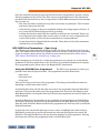
HPV 600 AC Drive Start Up, Open Loop . . . . . . . . . . . . . . . . . . . . . . . . . . . . . . . . . . . . . . . 3-2
System Overview . . . . . . . . . . . . . . . . . . . . . . . . . . . . . . . . . . . . . . . . . . . . . . . . . . . . . . . . . 3-2
Drive Programming . . . . . . . . . . . . . . . . . . . . . . . . . . . . . . . . . . . . . . . . . . . . . . . . . . . . . . . 3-2
HPV 600 Drive Parameters – Open Loop. . . . . . . . . . . . . . . . . . . . . . . . . . . . . . . . . . . . . 3-3
Parameter Settings . . . . . . . . . . . . . . . . . . . . . . . . . . . . . . . . . . . . . . . . . . . . . . . . . . . . . . . 3-4
Running the Car . . . . . . . . . . . . . . . . . . . . . . . . . . . . . . . . . . . . . . . . . . . . . . . . . . . . . . . . . . 3-6
Drive Parameter Reference, Open Loop . . . . . . . . . . . . . . . . . . . . . . . . . . . . . . . . . . . . . . 3-7
HPV 600 Drive Faults, Open Loop . . . . . . . . . . . . . . . . . . . . . . . . . . . . . . . . . . . . . . . . . 3-15
HPV 600 High Speed Adjustment — Open Loop . . . . . . . . . . . . . . . . . . . . . . . . . . . . . . . . 3-18
Car Balancing . . . . . . . . . . . . . . . . . . . . . . . . . . . . . . . . . . . . . . . . . . . . . . . . . . . . . . . . . . . 3-18
Motor Parameter Adjustments. . . . . . . . . . . . . . . . . . . . . . . . . . . . . . . . . . . . . . . . . . . . . 3-19
Speed Curve Setting and Adjustment . . . . . . . . . . . . . . . . . . . . . . . . . . . . . . . . . . . . . . . 3-20
Hoistway Learn for Normal Operation . . . . . . . . . . . . . . . . . . . . . . . . . . . . . . . . . . . . . . 3-21
HPV 600 AC Drive Start Up, Closed Loop . . . . . . . . . . . . . . . . . . . . . . . . . . . . . . . . . . . . . 3-22
System Overview . . . . . . . . . . . . . . . . . . . . . . . . . . . . . . . . . . . . . . . . . . . . . . . . . . . . . . . . 3-22
HPV 600 Drive Programming, Closed Loop. . . . . . . . . . . . . . . . . . . . . . . . . . . . . . . . . . 3-22
Drive Parameters – Closed Loop . . . . . . . . . . . . . . . . . . . . . . . . . . . . . . . . . . . . . . . . . . . 3-23
Parameter Settings . . . . . . . . . . . . . . . . . . . . . . . . . . . . . . . . . . . . . . . . . . . . . . . . . . . . . . 3-23
Running the Car . . . . . . . . . . . . . . . . . . . . . . . . . . . . . . . . . . . . . . . . . . . . . . . . . . . . . . . . . 3-26
HPV 600 Drive Parameter Reference, Closed Loop . . . . . . . . . . . . . . . . . . . . . . . . . . . 3-27
HPV 600 Drive Faults, Closed Loop . . . . . . . . . . . . . . . . . . . . . . . . . . . . . . . . . . . . . . . . 3-34
HPV 600 High Speed Adjustment — Closed Loop . . . . . . . . . . . . . . . . . . . . . . . . . . . . . . . 3-37
Car Balancing . . . . . . . . . . . . . . . . . . . . . . . . . . . . . . . . . . . . . . . . . . . . . . . . . . . . . . . . . . . 3-37
Motor Parameter Adjustments. . . . . . . . . . . . . . . . . . . . . . . . . . . . . . . . . . . . . . . . . . . . . 3-38
Speed Curve Setting and Adjustment . . . . . . . . . . . . . . . . . . . . . . . . . . . . . . . . . . . . . . . 3-38
HPV 600 Adaptive Tune . . . . . . . . . . . . . . . . . . . . . . . . . . . . . . . . . . . . . . . . . . . . . . . . . . . . 3-39
Normal Speed Learn Operation . . . . . . . . . . . . . . . . . . . . . . . . . . . . . . . . . . . . . . . . . . . . 3-40
Magnetek HPV 900 AC Vector Drive . . . . . . . . . . . . . . . . . . . . . . . . . . . . . . . . . . 3-41
HPV 900 Startup . . . . . . . . . . . . . . . . . . . . . . . . . . . . . . . . . . . . . . . . . . . . . . . . . . . . . . . . . . 3-41
System Overview . . . . . . . . . . . . . . . . . . . . . . . . . . . . . . . . . . . . . . . . . . . . . . . . . . . . . . . . 3-41
Drive Programming . . . . . . . . . . . . . . . . . . . . . . . . . . . . . . . . . . . . . . . . . . . . . . . . . . . . . . 3-41
Drive Parameters . . . . . . . . . . . . . . . . . . . . . . . . . . . . . . . . . . . . . . . . . . . . . . . . . . . . . . . . 3-42
Parameter Settings . . . . . . . . . . . . . . . . . . . . . . . . . . . . . . . . . . . . . . . . . . . . . . . . . . . . . . 3-43
Running the Car . . . . . . . . . . . . . . . . . . . . . . . . . . . . . . . . . . . . . . . . . . . . . . . . . . . . . . . . . 3-46
Drive Parameter Reference. . . . . . . . . . . . . . . . . . . . . . . . . . . . . . . . . . . . . . . . . . . . . . . . 3-46
Drive Faults . . . . . . . . . . . . . . . . . . . . . . . . . . . . . . . . . . . . . . . . . . . . . . . . . . . . . . . . . . . . 3-54
HPV 900 High Speed Adjustment . . . . . . . . . . . . . . . . . . . . . . . . . . . . . . . . . . . . . . . . . . . . 3-57
Car Balancing . . . . . . . . . . . . . . . . . . . . . . . . . . . . . . . . . . . . . . . . . . . . . . . . . . . . . . . . . . . 3-57
Motor Parameter Adjustments. . . . . . . . . . . . . . . . . . . . . . . . . . . . . . . . . . . . . . . . . . . . . 3-58
Speed Curve Setting and Adjustment . . . . . . . . . . . . . . . . . . . . . . . . . . . . . . . . . . . . . . . 3-58
HPV 900 Adaptive Tuning . . . . . . . . . . . . . . . . . . . . . . . . . . . . . . . . . . . . . . . . . . . . . . . . . . 3-60
Normal Speed Learn Operation . . . . . . . . . . . . . . . . . . . . . . . . . . . . . . . . . . . . . . . . . . . . 3-61
iv Manual # 42-02-2T00 F4, 10/6/09
Yaskawa F7 Drive . . . . . . . . . . . . . . . . . . . . . . . . . . . . . . . . . . . . . . . . . . . . . . . . . 3-62
Yaskawa Programmer . . . . . . . . . . . . . . . . . . . . . . . . . . . . . . . . . . . . . . . . . . . . . . . . . . . . . . 3-63
Digital Inputs . . . . . . . . . . . . . . . . . . . . . . . . . . . . . . . . . . . . . . . . . . . . . . . . . . . . . . . . . . . . . 3-63
Digital Outputs . . . . . . . . . . . . . . . . . . . . . . . . . . . . . . . . . . . . . . . . . . . . . . . . . . . . . . . . . . . . 3-64
Analog Outputs . . . . . . . . . . . . . . . . . . . . . . . . . . . . . . . . . . . . . . . . . . . . . . . . . . . . . . . . . . . . 3-64
Scaling Car Speed to Motor . . . . . . . . . . . . . . . . . . . . . . . . . . . . . . . . . . . . . . . . . . . . . . . . . . 3-64
Parameter: O1-03 (Display Scaling) . . . . . . . . . . . . . . . . . . . . . . . . . . . . . . . . . . . . . . . . 3-64
Maximum motor speed E1-04 (Default 60Hz) Setting . . . . . . . . . . . . . . . . . . . . . . . . . . . 3-65
Sample setup of O1-03 . . . . . . . . . . . . . . . . . . . . . . . . . . . . . . . . . . . . . . . . . . . . . . . . . . . 3-65
Speed Set Up . . . . . . . . . . . . . . . . . . . . . . . . . . . . . . . . . . . . . . . . . . . . . . . . . . . . . . . . . . . . . . 3-66
Inspection Startup (V/f mode/Open Loop/Closed Loop) . . . . . . . . . . . . . . . . . . . . . . . . . 3-67
Startup for Flux Vector Mode (Closed Loop) . . . . . . . . . . . . . . . . . . . . . . . . . . . . . . . . . 3-76
Scaling Adjustments . . . . . . . . . . . . . . . . . . . . . . . . . . . . . . . . . . . . . . . . . . . . . . . . . . . . . 3-76
Drive Faults . . . . . . . . . . . . . . . . . . . . . . . . . . . . . . . . . . . . . . . . . . . . . . . . . . . . . . . . . . . . . . 3-77
Motor Tuning (Flux Vector/Closed Loop Only) . . . . . . . . . . . . . . . . . . . . . . . . . . . . . . . . . 3-77
Normal Speed Learn Operation . . . . . . . . . . . . . . . . . . . . . . . . . . . . . . . . . . . . . . . . . . . . 3-77
Mitsubishi A500 Variable Frequency Drive . . . . . . . . . . . . . . . . . . . . . . . . . . . .3-78
A500 Startup and Adjustment . . . . . . . . . . . . . . . . . . . . . . . . . . . . . . . . . . . . . . . . . . . . . . . 3-78
Open Loop Volts/Hertz . . . . . . . . . . . . . . . . . . . . . . . . . . . . . . . . . . . . . . . . . . . . . . . . . . . 3-78
Mitsubishi A500, Magnetic Flux Vector Control . . . . . . . . . . . . . . . . . . . . . . . . . . . . . . 3-81
Normal Speed Learn Operation . . . . . . . . . . . . . . . . . . . . . . . . . . . . . . . . . . . . . . . . . . . . 3-84
Mitsubishi A500, Closed Loop Speed Control . . . . . . . . . . . . . . . . . . . . . . . . . . . . . . . . 3-85
Normal Speed Learn Operation . . . . . . . . . . . . . . . . . . . . . . . . . . . . . . . . . . . . . . . . . . . . 3-87
Magnetek DSD 412 DC Drive . . . . . . . . . . . . . . . . . . . . . . . . . . . . . . . . . . . . . . . 3-88
Hardware Modifications . . . . . . . . . . . . . . . . . . . . . . . . . . . . . . . . . . . . . . . . . . . . . . . . . . . 3-88
Drive Programming . . . . . . . . . . . . . . . . . . . . . . . . . . . . . . . . . . . . . . . . . . . . . . . . . . . . . . . . 3-88
Self Tune . . . . . . . . . . . . . . . . . . . . . . . . . . . . . . . . . . . . . . . . . . . . . . . . . . . . . . . . . . . . . . . . . 3-90
Inspection Start Up . . . . . . . . . . . . . . . . . . . . . . . . . . . . . . . . . . . . . . . . . . . . . . . . . . . . . . . . 3-91
Drive Faults . . . . . . . . . . . . . . . . . . . . . . . . . . . . . . . . . . . . . . . . . . . . . . . . . . . . . . . . . . . . . . 3-91
High Speed Adjust Magnetek DSD 412 . . . . . . . . . . . . . . . . . . . . . . . . . . . . . . . . . . . . . . . 3-92
Car Balancing . . . . . . . . . . . . . . . . . . . . . . . . . . . . . . . . . . . . . . . . . . . . . . . . . . . . . . . . . . . 3-92
Drive Parameters . . . . . . . . . . . . . . . . . . . . . . . . . . . . . . . . . . . . . . . . . . . . . . . . . . . . . . . . . . 3-93
S-Curve Pattern Adjustments . . . . . . . . . . . . . . . . . . . . . . . . . . . . . . . . . . . . . . . . . . . . . . . . 3-93
Speed Pots. . . . . . . . . . . . . . . . . . . . . . . . . . . . . . . . . . . . . . . . . . . . . . . . . . . . . . . . . . . . . . 3-93
Acceleration / Deceleration Pots . . . . . . . . . . . . . . . . . . . . . . . . . . . . . . . . . . . . . . . . . . . 3-94
S Curve Knee Pots . . . . . . . . . . . . . . . . . . . . . . . . . . . . . . . . . . . . . . . . . . . . . . . . . . . . . . . 3-94
Dead Zone Pattern Ramp . . . . . . . . . . . . . . . . . . . . . . . . . . . . . . . . . . . . . . . . . . . . . . . . . 3-94
Final S-Curve Adjustments. . . . . . . . . . . . . . . . . . . . . . . . . . . . . . . . . . . . . . . . . . . . . . . . 3-94
Normal Speed Learn Operation . . . . . . . . . . . . . . . . . . . . . . . . . . . . . . . . . . . . . . . . . . . . 3-98
v
Section 4. Release to Normal Operation
In this Section . . . . . . . . . . . . . . . . . . . . . . . . . . . . . . . . . . . . . . . . . . . . . . . . . . . . . . 4-1
Limit Board Adjustment . . . . . . . . . . . . . . . . . . . . . . . . . . . . . . . . . . . . . . . . . . . . .4-2
Limit Board (Standard) . . . . . . . . . . . . . . . . . . . . . . . . . . . . . . . . . . . . . . . . . . . . . . . . . . . . . . 4-3
Input Definitions . . . . . . . . . . . . . . . . . . . . . . . . . . . . . . . . . . . . . . . . . . . . . . . . . . . . . . . . . 4-4
Diagnostic and Mode LEDs . . . . . . . . . . . . . . . . . . . . . . . . . . . . . . . . . . . . . . . . . . . . . . . . 4-5
Operation, Inspection Setup Before High Speed . . . . . . . . . . . . . . . . . . . . . . . . . . . . . . . 4-7
Operation, Normal Setup High Speed. . . . . . . . . . . . . . . . . . . . . . . . . . . . . . . . . . . . . . . . 4-7
Operation, Normal. . . . . . . . . . . . . . . . . . . . . . . . . . . . . . . . . . . . . . . . . . . . . . . . . . . . . . . . 4-8
2K Limit/Gripper Board . . . . . . . . . . . . . . . . . . . . . . . . . . . . . . . . . . . . . . . . . . . . . . . . . . . . . 4-9
Parameter Entry. . . . . . . . . . . . . . . . . . . . . . . . . . . . . . . . . . . . . . . . . . . . . . . . . . . . . . . . . 4-13
Inspection Learn . . . . . . . . . . . . . . . . . . . . . . . . . . . . . . . . . . . . . . . . . . . . . . . . . . . . . . . . 4-14
Normal Learn . . . . . . . . . . . . . . . . . . . . . . . . . . . . . . . . . . . . . . . . . . . . . . . . . . . . . . . . . . . 4-15
Operating Examples . . . . . . . . . . . . . . . . . . . . . . . . . . . . . . . . . . . . . . . . . . . . . . . . . . . . . 4-16
Final Test . . . . . . . . . . . . . . . . . . . . . . . . . . . . . . . . . . . . . . . . . . . . . . . . . . . . . . . . .4-19
Buffer Tests . . . . . . . . . . . . . . . . . . . . . . . . . . . . . . . . . . . . . . . . . . . . . . . . . . . . . . . . . . . . . . . 4-19
Preparation. . . . . . . . . . . . . . . . . . . . . . . . . . . . . . . . . . . . . . . . . . . . . . . . . . . . . . . . . . . . . 4-19
Contract Speed Buffer Test - Car . . . . . . . . . . . . . . . . . . . . . . . . . . . . . . . . . . . . . . . . . . . 4-20
Contract Speed Buffer Test - Counterweight . . . . . . . . . . . . . . . . . . . . . . . . . . . . . . . . . 4-21
Governor Safety Test . . . . . . . . . . . . . . . . . . . . . . . . . . . . . . . . . . . . . . . . . . . . . . . . . . . . . . . 4-22
Preparation. . . . . . . . . . . . . . . . . . . . . . . . . . . . . . . . . . . . . . . . . . . . . . . . . . . . . . . . . . . . . 4-22
Governor Safety Test - Overspeed - 1025 Regulator . . . . . . . . . . . . . . . . . . . . . . . . . . . 4-22
Normal Terminal Stopping (NTS) Test . . . . . . . . . . . . . . . . . . . . . . . . . . . . . . . . . . . . . . . . 4-23
Top Floor Test Procedure . . . . . . . . . . . . . . . . . . . . . . . . . . . . . . . . . . . . . . . . . . . . . . . . . 4-23
Bottom Floor Test Procedure . . . . . . . . . . . . . . . . . . . . . . . . . . . . . . . . . . . . . . . . . . . . . . 4-23
Reset Floor Table . . . . . . . . . . . . . . . . . . . . . . . . . . . . . . . . . . . . . . . . . . . . . . . . . . . . . . . . 4-23
Emergency Terminal . . . . . . . . . . . . . . . . . . . . . . . . . . . . . . . . . . . . . . . . . . . . . . . . . . . . . . . 4-24
Magnetek HPV 600 Drive. . . . . . . . . . . . . . . . . . . . . . . . . . . . . . . . . . . . . . . . . . . . . . . . . 4-24
Magnetek HPV 900 Drive. . . . . . . . . . . . . . . . . . . . . . . . . . . . . . . . . . . . . . . . . . . . . . . . . 4-24
Mitsubishi A500 Drive . . . . . . . . . . . . . . . . . . . . . . . . . . . . . . . . . . . . . . . . . . . . . . . . . . . 4-24
Top Floor Test Procedure . . . . . . . . . . . . . . . . . . . . . . . . . . . . . . . . . . . . . . . . . . . . . . . . . 4-24
Bottom Floor Test Procedure . . . . . . . . . . . . . . . . . . . . . . . . . . . . . . . . . . . . . . . . . . . . . . 4-25
vi Manual # 42-02-2T00 F4, 10/6/09
Section 5. Tricon Configuration
In this Section . . . . . . . . . . . . . . . . . . . . . . . . . . . . . . . . . . . . . . . . . . . . . . . . . . . . . . 5-1
HHU Basics . . . . . . . . . . . . . . . . . . . . . . . . . . . . . . . . . . . . . . . . . . . . . . . . . . . . . . . .5-2
Connection . . . . . . . . . . . . . . . . . . . . . . . . . . . . . . . . . . . . . . . . . . . . . . . . . . . . . . . . . . . . . . . . 5-2
Operation . . . . . . . . . . . . . . . . . . . . . . . . . . . . . . . . . . . . . . . . . . . . . . . . . . . . . . . . . . . . . . . . . 5-3
Moving within the Current Menu . . . . . . . . . . . . . . . . . . . . . . . . . . . . . . . . . . . . . . . . . . . 5-3
Moving Between Submenus . . . . . . . . . . . . . . . . . . . . . . . . . . . . . . . . . . . . . . . . . . . . . . . . 5-3
Activating a Submenu . . . . . . . . . . . . . . . . . . . . . . . . . . . . . . . . . . . . . . . . . . . . . . . . . . . . . 5-3
Making an Entry in a Function Screen . . . . . . . . . . . . . . . . . . . . . . . . . . . . . . . . . . . . . . . 5-4
Return to Last Menu . . . . . . . . . . . . . . . . . . . . . . . . . . . . . . . . . . . . . . . . . . . . . . . . . . . . . . 5-4
Jumping . . . . . . . . . . . . . . . . . . . . . . . . . . . . . . . . . . . . . . . . . . . . . . . . . . . . . . . . . . . . . . . . 5-4
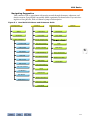
Navigating Suggestion. . . . . . . . . . . . . . . . . . . . . . . . . . . . . . . . . . . . . . . . . . . . . . . . . . . . . 5-5
Main Menus . . . . . . . . . . . . . . . . . . . . . . . . . . . . . . . . . . . . . . . . . . . . . . . . . . . . . . .5-6
Car Diagnostics . . . . . . . . . . . . . . . . . . . . . . . . . . . . . . . . . . . . . . . . . . . . . . . . . . . . . . . . . . . . 5-6
States Submenu Screen . . . . . . . . . . . . . . . . . . . . . . . . . . . . . . . . . . . . . . . . . . . . . . . . . . . . 5-7
Car Errors . . . . . . . . . . . . . . . . . . . . . . . . . . . . . . . . . . . . . . . . . . . . . . . . . . . . . . . . . . . . . . 5-19
Input & Outputs . . . . . . . . . . . . . . . . . . . . . . . . . . . . . . . . . . . . . . . . . . . . . . . . . . . . . . . . . 5-22
Car Setup Menu . . . . . . . . . . . . . . . . . . . . . . . . . . . . . . . . . . . . . . . . . . . . . . . . . . . . . . . . . . 5-38
Parameters . . . . . . . . . . . . . . . . . . . . . . . . . . . . . . . . . . . . . . . . . . . . . . . . . . . . . . . . . . . . . 5-38
Floor Table . . . . . . . . . . . . . . . . . . . . . . . . . . . . . . . . . . . . . . . . . . . . . . . . . . . . . . . . . . . . . 5-50
CE Indicator Set Up -View & Edit Screen . . . . . . . . . . . . . . . . . . . . . . . . . . . . . . . . . . . . 5-54
Position Indicators- View & Edit Screens (CTOP, CSTA, or HALL Board). . . . . . . . . 5-57
PI Board Setup - View & Edit . . . . . . . . . . . . . . . . . . . . . . . . . . . . . . . . . . . . . . . . . . . . . . 5-61
BMS Setup . . . . . . . . . . . . . . . . . . . . . . . . . . . . . . . . . . . . . . . . . . . . . . . . . . . . . . . . . . . . . 5-66
Car Lockout Setup . . . . . . . . . . . . . . . . . . . . . . . . . . . . . . . . . . . . . . . . . . . . . . . . . . . . . . . 5-68
Clock . . . . . . . . . . . . . . . . . . . . . . . . . . . . . . . . . . . . . . . . . . . . . . . . . . . . . . . . . . . . . . . . . . 5-70
Reset Errors . . . . . . . . . . . . . . . . . . . . . . . . . . . . . . . . . . . . . . . . . . . . . . . . . . . . . . . . . . . . 5-71
Reset Parameters . . . . . . . . . . . . . . . . . . . . . . . . . . . . . . . . . . . . . . . . . . . . . . . . . . . . . . . . 5-71
Reset Floor Table . . . . . . . . . . . . . . . . . . . . . . . . . . . . . . . . . . . . . . . . . . . . . . . . . . . . . . . . 5-72
Reset BMS. . . . . . . . . . . . . . . . . . . . . . . . . . . . . . . . . . . . . . . . . . . . . . . . . . . . . . . . . . . . . . 5-72
Dispatcher Setup . . . . . . . . . . . . . . . . . . . . . . . . . . . . . . . . . . . . . . . . . . . . . . . . . . . . . . . . . . 5-73
Parameters . . . . . . . . . . . . . . . . . . . . . . . . . . . . . . . . . . . . . . . . . . . . . . . . . . . . . . . . . . . . . 5-73
Floor Table . . . . . . . . . . . . . . . . . . . . . . . . . . . . . . . . . . . . . . . . . . . . . . . . . . . . . . . . . . . . . 5-81
Dispatcher Input & Outputs . . . . . . . . . . . . . . . . . . . . . . . . . . . . . . . . . . . . . . . . . . . . . . 5-82
Clock . . . . . . . . . . . . . . . . . . . . . . . . . . . . . . . . . . . . . . . . . . . . . . . . . . . . . . . . . . . . . . . . . . 5-83
BMS Setup . . . . . . . . . . . . . . . . . . . . . . . . . . . . . . . . . . . . . . . . . . . . . . . . . . . . . . . . . . . . . 5-84
Reset Dispatcher Parameters . . . . . . . . . . . . . . . . . . . . . . . . . . . . . . . . . . . . . . . . . . . . . . 5-85
Reset Dispatcher Floor Table . . . . . . . . . . . . . . . . . . . . . . . . . . . . . . . . . . . . . . . . . . . . . . 5-85
Reset Dispatcher BMS Parameters . . . . . . . . . . . . . . . . . . . . . . . . . . . . . . . . . . . . . . . . . 5-85
Network . . . . . . . . . . . . . . . . . . . . . . . . . . . . . . . . . . . . . . . . . . . . . . . . . . . . . . . . . . . . . . . . . . 5-85
Fireman Operation Setup . . . . . . . . . . . . . . . . . . . . . . . . . . . . . . . . . . . . . . . . . . 5-86
Operation . . . . . . . . . . . . . . . . . . . . . . . . . . . . . . . . . . . . . . . . . . . . . . . . . . . . . . . . . . . . . . . . 5-86
Parameters . . . . . . . . . . . . . . . . . . . . . . . . . . . . . . . . . . . . . . . . . . . . . . . . . . . . . . . . . . . . . 5-86
Code Differences . . . . . . . . . . . . . . . . . . . . . . . . . . . . . . . . . . . . . . . . . . . . . . . . . . . . . . . . 5-88
vii
viii Manual # 42-02-2T00 F4, 10/6/09
•
•
•
•
•
•
•
Tricon
Car Controller
Cartop Station
Car Station
Dispatcher
Hand Held Unit
Operating Modes
1
Tricon General Information
Tricon
The job prints are the primary document necessary to install the controller. The job prints and
manual together provide information to install, adjust, and troubleshoot the controller. Study
the job prints and read the manual before starting work. Call MCE with any questions you may
have.
Depending on the job, the Tricon system may include:
• Controller: Configured according to customer job survey.
• Car top station: Interface/interconnect/control box between car-mounted equipment and
the car controller.
• Car top junction box: Some jurisdictions require that components normally mounted
inside the Car top station be in the controller cabinet instead. In these instances, a smaller
car top junction box is used in place of the car top station.
• Car station: Optional, car operating panel to cartop interface.
• Group Dispatcher: Dispatching components may be installed in a separate cabinet or in
one of the car controller cabinets.
• Hand Held Unit: The HHU is a hand-held programming and diagnostic tool that plugs
into the Tricon serial communications stream using a simple, telephone-style plug.
Specifications:
• Performance up to 300 feet per minute
• Up to 32 single or double-openings
• Up to 6 cars in a control group
• Extensive field programmability
1-1
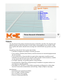
Tricon General Information
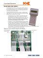
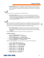
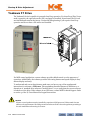
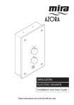
Car Controller
Tricon controllers may be ordered in ASME
A17.1-2000 or other compliance versions.
Tricon is compatible with drives including:
• Magnetek HPV 600 AC vector drive
• Magnetek HPV 900 AC vector drive
• Yaskawa F7 AC vector drive
• Mitsubishi A500 AC drive
• Magnetek DSD412 DC drive
Tricon may use open or closed loop control.
A typical Tricon controller with an AC drive
is shown to the right.
Jobs may use different cabinet sizes depending upon the number and type of boards
required, drive size, the presence or absence
of group dispatcher components, and environmental requirements.
1-2 Manual # 42-02-2T00
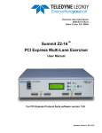
Car Controller
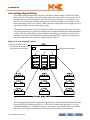
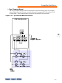
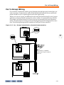
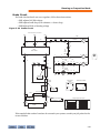
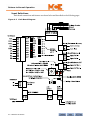
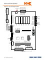
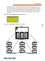
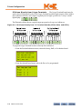
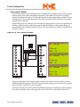
Figure 1.1
System Block Diagram
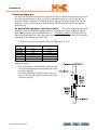
Landing System
Floating sensor head on 2-inch steel tape
3 rows of 6-inch magnetic strips
Middle row: Floor level
Right: Slow down/down, Rear door zone
Left: Slow down/up, Front door zone
Hand Held Unit (HHU):
Used to program Cartop, Controller, and Dispatcher.
Plugs into network using phone jack style connection.
Cartop Station
Inspection Operation
Landing System I/F Board
Door I/F (may alternately be in Controller)
Car call I/O
Serial link
Controller
Operating mode selection
Hall calls (Simplex or Swing)
Machine room inspection controls
Safety string
AC, DC, M/G capable
Group Dispatcher
Separate or in controller cabinet
Multiple car dispatching
Traffic mode control (lobby peak, etc.)
Hall calls
Serial link
= PW5 hub for serial communication
between controller boards
= Gateway board required for
group communication. May be
in controller or in dispatcher
1-3
1
Tricon General Information
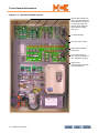
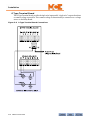
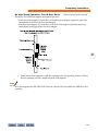
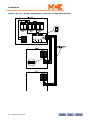
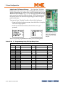
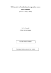
Figure 1.2
Typical Controller Layout
I/O 24 base boards use
plug-in modules like the
one indicated to perform
a variety of input and
output needs (hall/car
calls, position indicators, etc.)
5V Power Supply
Microprocessor board
PW5 communications
hub board
Limit board (may be
A17.1 2000 compliant or
non-compliant version)
Relay board
(MR Inspection controls
in area indicated)
1-4 Manual # 42-02-2T00
Car Controller
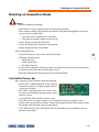
Controller Circuit Boards
The following board types may be used depending on the specific job:
• 5V, 6A Power Supply: Provides 5-volt DC power distributed through the PW5 board.
• CPU: The Central Processing Unit performs control processing. (The same board, fitted
with different software, is used in group dispatcher applications.)
• PW5: Major system components communicate through a high-speed serial link. The PW5
board provides a point-of-connection for eight communicating components. One of the
connection points is always used by the system CPU, the other seven are available for
other connections. These connections also distribute +5V power.
• I/O 24 Board: Depending upon the software installed, I/O 24 boards may be used as Car
Controller boards, Hall I/O boards, Position Indicator, Expansion, Car Call Lockout, or
Dispatch boards. In all cases, functionality can be expanded by “plugging in” from one to
three expansion boards. (Left-to-right, viewed from the front, the three expansion board
locations are A, B, and C). When used as a Car Controller, the I/O 24 board may have an
Access board plugged into its C position or all expansion positions may be empty. Please
refer to “I/O 24 Board with Terminal Boards at A, B, and C Positions” on page 1-6.
Expansion boards include:
• L Terminal board: Used for car or hall calls, provides 8 paired input/output combinations. The input services the call button and the output enables the button lamp.
• O Terminal board: Used for general purpose I/O, provides 8 independent inputs and 8
independent outputs. The common bus (power or ground) for the outputs is determined by a connection to the Relay board.
• F Terminal board: Used for general purpose I/O, provides 8 independent inputs and 8
independent outputs. Each output provides two connection points. The common bus
(power or ground) for the outputs is determined by a connection to the Relay board.
• Access board: Used when top and or bottom hoistway access is provided. Mounts on
the I/O 24 (Controller-only position) board in the C location.
• CE Driver board: Interfaces to third-party audible or visual devices. The type (heavy duty
or standard) and number of driver boards provided depends on the particular job.
• Limit board or 2K Limit/Gripper board: Limit board provides car Feet-Per-Minute setting, limits overspeed conditions, monitors speed feedback, controls hoistway learn operations. 2K Limit/Gripper performs the same functions and additionally limits unintended
motion and controls an external rope gripper. Refer to Section 4 for more information.
• PI board: I/O 24 board with position indicator software and up to three O-type Terminal
boards. Provides expandable position indicator control.
• Gateway board: When a car is part of a group, a Gateway board is provided in the controller cabinet to communicate with the group dispatcher.
• CCL board: I/O 24 board, with terminal boards as required to accommodate hard wired
car call lockout switch inputs. Please refer to “Car Lockout Setup” on page 5-68.
1-5
1
Tricon General Information
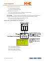
Figure 1.3
I/O 24 Board with Terminal Boards at A, B, and C Positions
You can identify the
board by the label on the
programmed chip in this
location.
Plug in for the Hand Held
Unit (HHU)
Indicates location (A) and
terminal board type (F).
Terminal board locations
are A, B, and C from left
to right.
1-6 Manual # 42-02-2T00
A
B
C
Car Controller
• RB board: Provides power bus fuses and heavy duty relays for drive, brake, and motor control. Also provides mode (Inspection/Normal) and motion control switches for operating
the elevator from the controller cabinet. One of three different RB boards is used depending upon job requirements. The 2K Relay board is described here. The others will have
“subsets” of 2K controls and indicators.
1
Relay Board switches:
•
•
•
•
Stop/Run: Enables or disables motor movement by opening/closing the safety string.
Inspection/Auto: Mode select for inspection or automatic (normal) running.
Door Disable/Normal: Disable/Enable door operation.
Gate Bypass: Select Bypass to “jumper out” the gate contacts from the safety string (A17.1/
2000 compliant boards only). Buzzer will sound when in Bypass position.
• Door Bypass: Select Bypass to “jumper out” the door contacts from the safety string
(A17.1/2000 compliant boards only). Buzzer will sound when in Bypass position.
• Buzzer volume: The volume of the buzzer for the Gate and Door Bypass switches is set
using one of three SEL BUZ jumpers. JP1 = high volume. JP2 = medium volume. JP3 =
low volume.
• The bypass switches may be enabled or disabled by setting car Parameter 125.
• Insp/Up: With the Inspection/Auto switch in the Inspection position, runs the car up the
hoistway when held down. Car will automatically stop when it reaches the Normal Limit
switch.
• Insp/Down: With the Inspection/Auto switch in the Inspection position, runs the car
down the hoistway when held down. Car will automatically when it reaches the Normal
Limit switch.
1-7
Tricon General Information
Relay Board LEDs:
•
•
•
•
•
•
•
•
•
•
•
LUNT: Up Normal Terminal - lights yellow when this switch is open.
LDNT: Down Normal Terminal - lights yellow when this switch is open.
LLCK: Lights green when door lock contacts are all closed.
LSAF: Lights green when the safety string is made up.
LGATE: Lights green when gate contacts are all closed.
LDGP: Gate/Lock Bypass - lights green when either bypass switch is enabled.
110VDC: Lights red when 110VDC power is present.
24VDC: Lights red when 24VDC power is present.
LDFZ: Lights red when the car is in a front door zone.
LDRZ: Lights red when the car is in a rear door zone.
Relay Sequence: The car is not allowed to start if the Relay Sequence input to the Controller board is OFF. The seven LEDs below are associated with the relays in the sequence. The
relays monitor various inputs. If the monitored input is active, the relay will change state,
the associated LED will light red.
• LPR1, LPR2: LEDs for Potential relays 1 and 2 respectively.
• LUR: LED for Up Run relay.
• LDR: LED for Down Run relay.
• LMSR: LED for Medium Speed relay.
• LHSR: LED for High Speed relay.
• LBKR: LED for Brake relay.
Additional circuit boards may be used, including:
•
•
•
•
•
•
EXT 1 board: Used for additional input/output capability.
BMS board: Used to interface to a modem for central monitoring.
Door board(s): Used if required for specific door operators.
HHSW board: Modem interface for monitoring applications.
SLH board: Fuse board for specific applications.
CE Fixture boards with LON interface: Used when extensive external fixtures are required.
1-8 Manual # 42-02-2T00
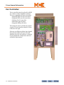
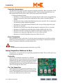
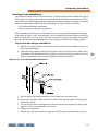
Cartop Station
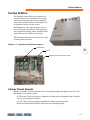
Cartop Station
The standard cartop station provides both an
interface between the controller and car equipment like leveling systems and door operators
and a cartop control station for running the car
on Inspection mode from the cartop.
The illustration to the right shows an exterior
view of a typical cartop station. The emergency
stop, inspection/normal, safety, and directional
control buttons are visible across the top.
The illustration below shows the layout of a typical cartop station interior.
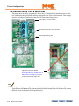
Figure 1.4
Typical Cartop Station Layout
CTOP board
1
5V PS
M30024 (landing system) board
Cartop Circuit Boards
Like the controller, the circuit boards in the cartop station might vary slightly from job to job,
depending upon customer needs.
• CTOP board: The I/O 24 board, configured with appropriate Terminal boards to handle
the car operating panel interface.
• 5V PS: A five-volt power supply to handle low voltage component needs.
• M30024: Interface board for the SET 9000 cartop landing system.
1-9
Tricon General Information
Cartop Junction Box
Some installations require that components
typically mounted in the cartop station be
located in the controller cabinet instead. In
these cases, a smaller cartop interconnect box
is used, supporting only the landing system
interface board. A typical cartop junction box
is shown to the right.
Car Station
The car station is a semi-custom addition to a
user-provided car operating panel. The car
station converts the discrete inputs of the car
operating panel into a high speed serial
stream, communicating with the car controller through a simple, twisted-strand cable.
The car station allows the bulk of the traveler cable to be reduced since it is no longer necessary
to use individual wires between the car and the controller for each car operating panel button or
lamp.
Please contact MCE Sales support if you are interested in a car station for your Tricon installation.
1-10 Manual # 42-02-2T00
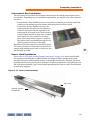
Dispatcher
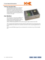
Dispatcher
The Tricon dispatcher provides centralized control of
up to six cars to efficiently
handle building traffic. The
dispatcher also controls car
parking assignment, special operating modes (i.e.,
lobby peak), and group
response during atypical
operation (i.e., operation
during fire conditions,
emergency power conditions, etc.).
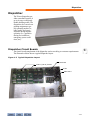
Dispatcher Circuit Boards
The circuit board complement of the dispatcher varies according to customer requirements.
The illustration below shows a typical dispatcher layout.
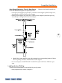
Figure 1.5
Typical Dispatcher Layout
CPU board
DHALL (I/O 24) boards
5V PS
PW5 board
1-11
1
Tricon General Information
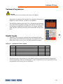
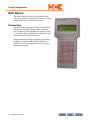
Hand Held Unit (HHU)
The Hand Held Unit is used to set up and troubleshoot the Tricon controller, cartop, car station, and dispatcher components.
The Hand Held Unit allows you to set system parameters and
view status and error information.
You plug the Hand Held Unit into a common “telephone jack”
style connector on one of the circuit boards associated with the
microprocessor you want to view or edit:
• Car Network: To view or edit the car network CPU, plug
the Hand Held Unit into any car network (controller or
cartop station) board with a phone jack (I/O 24, CE, or PI
boards). Car network I/O 24 boards can be identified by
the sticker on the square IC in the upper left corner of the
board, which will be labeled “Hall” or “CTRV”.
• Dispatcher: To view or edit the dispatching (group control)
network, plug the Hand Held Unit into any dispatcher I/O
24 board. Typically, the dispatcher is housed in a separate
cabinet from the controller cabinets of the cars it controls.
(If you have a dispatcher housed in the same cabinet with
a car controller, you can identify the dispatcher I/O 24 board by the “dHall” sticker on the
square IC in the upper left corner of the board.)
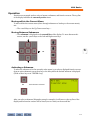
Figure 1.6
I/O 24, Controller Board for Car Network
IC with identifying
software sticker
1-12 Manual # 42-02-2T00
HHU connector
Control Parameters
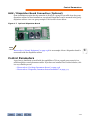
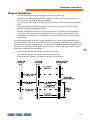
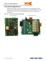
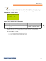
HHU / Dispatcher Board Connection (Optional)
Some installations require that the networks of all cars in a group be accessible from the group
dispatcher cabinet. In these installations, an optional Dispatcher board is mounted in the group
dispatcher cabinet. A two-car group example of this board is shown below.
Figure 1.7
Optional Dispatcher Board
Note
Please refer to “Seismic Equipment” on page 2-38 for an example of how a Dispatcher board is
connected inside the dispatcher cabinet.
Control Parameters
A good way to familiarize yourself with the capabilities of Tricon car and group controls is to
read through the control parameters tables. If you have not installed Tricon controls before, this
is a very valuable process.
• Please refer to “Car Setup, Parameters Screen” on page 5-38
• Please refer to “Dispatcher, Parameter Screen Parameters” on page 5-74
1-13
1
Tricon General Information
Operating Modes
This section describes controller operating modes, including:
•
•
•
•
•
Inspection Operation
Car Switch (Attendant) Operation
Emergency Power Operation
Code Blue Operation
Seismic Operation
Inspection Operation
Inspection priority order is:
• Top of car
• Access
• Controller
In inspection, a car operates at slow speed using up and down buttons. The car will stop as soon
as the buttons are released.
Danger
Changing parameters 76 and 85 may allow the drive to remain on after the buttons are
released. Make sure 76 and 85 are set to 0 (zero) when the car is released to normal service.
Controller Inspection
Operate the car using the controller UP or DOWN
inspection buttons. A car running in either direction will
automatically stop when it reaches the normal terminal
switch in that direction. Pressing and holding both UP
and DOWN buttons at the same time will open the doors
if the car is stopped at a door zone.
Car Top Inspection
In this mode, the car is operated by pushing the cartop
UP or DOWN and SAFETY buttons. Doors will open if
both UP and DOWN buttons are pressed for more than
two seconds while the car is in a door zone.
Access Inspection
To initiate access, the car must be on in car inspection. In access mode, the car moves when a
top/bottom access switch is moved to the up/down direction. The car moves only until the
hoistway mounted access switch for top/bottom access is opened.
• Pressing the bottom floor car call will close the doors and move the car down. The next car
call will move the car up.
• If car open and close buttons are operational, a door will only open if the car is in a door
zone.
1-14 Manual # 42-02-2T00
Operating Modes
Car Switch Operation
Tricon supports attendant mode, self-leveling operation when using standard or manual door
operation software. Standard drive software, CTRL No.1, for cars 200 fpm or less, or CTRL
No.2, for cars above 200 fpm, can be used. All I/O boards required for standard automatic
operation are required for car switch operation. Manual door software can be used with a standard car station or car switch.
Running the Car From the Hand Held
The car may be run from the hand held unit for tune up purposes:
• The door disable switch on the controller should be on.
• Entering a floor in the simplex parking floor, parameter 141, moves the car to the entered
floor.
• Parking delay time, parameter 142, should be set to 0.
• Before the car is run from the car switch, the parking floor must be set to 0
and the door disable switch must be off. If the door disable switch is on, the car
switch will latch the top and bottom floor car calls.
Setting Up Car Switch Operation
1
To use car switch operation:
• Put the car on attendant operation by setting the B2 input on the CSTA board (car station)
ON.
• The field terminal board used on the CSTA I/O board (for car calls) must be the “O” type.
This type of field terminal board does not connect the input to the output for the call
acknowledge light.
• Parameters and floor tables are set as on a standard job except:
• 133: Yes (Inspection flag. Prevents car calls from latching.)
• 139: 0 (Prevents car going out of service if delayed.)
• 141: 0 (Parking floor.)
• 142: 0 (Parking delay time.)
Operation
When the car switch is moved to the up direction, the top floor car call input will be activated.
This will start the car in motion. Moving the handle to the center position (top floor car call
input off), will allow the car to slow down and level to the next available floor.
When the car switch is moved to the down direction, the bottom floor car call input will be activated. This will start the car in motion. Moving the handle to the center position (bottom floor
car call input off), will allow the car to slow down and level to the next available floor.
A one floor run requires the call-input to be off within two seconds of the start of the car.
When running the car on door disconnect from the hand held, the car switch handle will latch
the calls. Remove the car from door disconnect operation before running the car with the
switch.
1-15
Tricon General Information
Car Door Operation
If a door operator is used, the software must be standard VVD software. Set up is as described
above. To close the door, the door close input to the CTOP board must be turned on. As is the
case for car switch operation, car direction and starting are controlled through the top and bottom floor car calls. The car door will not close without a call above or below the car.
Hall Call Operation
Hall calls may be used and will cause the attendant buzzer to sound when a hall call is registered
and the car door is not in motion. If you are providing an annunciation light panel in the car,
wire the hall call wires to the lights. The buzzer will sound for 5 seconds, then switch off for 10
seconds. This will continue until you start the car.
The car will automatically slow down for hall calls if it is traveling in the proper direction. To
stop for a hall call in the opposite direction, release the car switch to stop at the floor. When you
stop at a floor, up and down calls at the floor are cancelled. To bypass hall calls, you can wire a
bypass button to the bypass input on the CSTA board. When this input is on, the car will not
slow down for calls as you pass them.
Emergency Power Operation
Tricon provides the following types of emergency power operations. The desired operation
requires setting car and dispatcher parameters and operation of the car select inputs to the dispatcher. In the description that follows, emergency power operation is described as Phase I and
Phase 2 operation. Phase I recalls the cars to the recall floor. Phase 2 is operating the car from
the car station while on emergency power.
Operation Modes:
• 1-Automatic sequential phase 1 recall with automatic phase 2 car selection.
• 2-Automatic sequential phase 1 recall with manual phase 2 car selection.
• 3-Manual phase I recall with manual phase 2 car selection.
All the operations above allow the car selection switches to override automatic operation and
select the car manually for phase 1 recall or phase 2 operation.
The dispatcher provides pre-transfer operation when changing to and from normal power.
When the pre-transfer input is activated, all running cars will stop at the next available floor
and wait for transfer of emergency power to normal power. This input should be active at least
fifteen seconds before the emergency power is transferred to normal power. All power transfers
should allow a complete power down of the equipment before the new power source is switched
on. All cars and the dispatcher should have power provided at the same time.
Software Required
The controller provides emergency power when used with dispatcher version 6 and above software. The car requires version 6 software for MPU, CTRL (1 or 2), and CTOP boards. The dispatcher requires version 6 software for the MPU. Other car and dispatcher system boards may
be version 5 software.
1-16 Manual # 42-02-2T00
Operating Modes
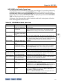
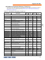
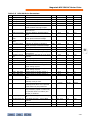
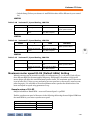
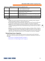
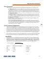
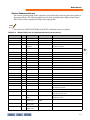
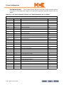
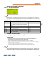
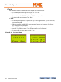
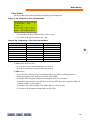
Input Mapping
When emergency power is enabled, the dispatcher will require six inputs for the lobby selection
switches and two inputs for emergency power and emergency power off. Emergency power
operation is enabled by setting dispatcher parameter 20, Emergency Power Recall Timeout
time, to a value other than zero. Assuming you want emergency power operation, you should set
a minimum of 45 seconds for this parameter. This will cause the dispatcher to provide the
inputs for emergency power as described above. The inputs used for emergency power will be
located on the DHALL board “B” location. This is the second group of 8 inputs on this board.
They were previously used for the first 8 hall calls. All hall call wires will have to be shifted to
the right by 8 locations.
The bottom floor up call will not start on the DHALL ‘CL1' location. This will continue on to the
DHALL 2 board. You may need an additional I/O board or I/O board field terminal board to
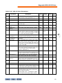
relocate all of the hall calls. Following is a list of new inputs that will be created when the emergency power option is provided. All inputs will select the function when turned on.
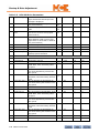
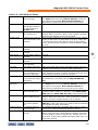
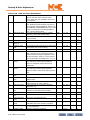
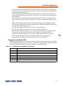
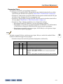
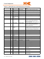
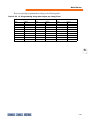
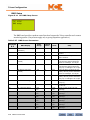
Table 1.1
Emergency Power Option Inputs
Input
Function
B1-1
Car 1 selected
B1-2
Car 2 selected
B1-3
Car 3 selected
B1-4
Car 4 selected
B1-5
Car 5 selected
B1-6
Car 6 selected
B1-7
Pre-transfer. This will stop all running cars at the next floor and wait for the
removal of this input.
B1-8
Emergency power operation.
1
1-17
Tricon General Information
Car Parameters Description and Operation
The car uses two parameters for emergency power — parameters 108 and 155. Parameter 108,
the fire recall floor, is used as the recall floor for fire service and emergency power. Parameter
155, emergency power enabled, must be set to yes when dispatcher parameter 20, emergency
power recall time, is not set to 0. This will enable emergency power operation on the car and the
dispatcher. Once parameter 155 is set to ‘yes’, the car will not operate if it cannot communicate
with the dispatcher.
Dispatcher Parameters Description and Operation
The dispatcher uses three parameters for emergency power:
• Parameter 20, emergency power recall time out.
• Parameter 21, emergency power manual operation phase 1 and phase 2.
• Parameter 22, emergency power manual phase 2 select.
Parameter 20 sets the time the dispatcher will wait before aborting a phase 1 recall if a car is
being held or cannot run. If a car is passed over, the dispatcher will try again after returning all
of the other cars. A car that has not returned can be manually selected at any time with the manual selection switch. If the manual switches have not been provided, you can force the dispatcher to try another phase 1 return sequence by putting the phase 2 car in inspection
operation. A second function of parameter 20 is to turn off emergency power operation. If the
time is set to 0, emergency power operation will be disabled and the inputs will be remapped as
described above.
Parameters 21 and 22 Limit Phase 1 and Phase 2 Operation.
• Operation Mode 1: [Auto recall / Auto phase 2 / Manual override]. Parameters 21 and 22
are set to “No”. The emergency power will operate as follows:
• All cars will sequentially return to the lobby, phase 1 operation.
• After the cars have returned or have been bypassed, the first car will return to service.
• The car select switches will allow you to select another car. Selecting another car will
start a phase 1 recall operation of the car in service.
• Operation Mode 2: [Auto recall / Manual phase 2 / Manual override]
• Parameter 21 set to “Yes” will allow you to recall all cars starting with cars that have
their manual select switch on and then all remaining cars afterwards. The manually
selected car will then be returned to service for phase 2 operation.
• Operation Mode 3: [Manual recall / Manual override]
• Parameters 22 set to “No” will allow only cars with their manual select switch on to be
selected. With the select switch on, the car will be selected to recall. When finished
with the recall operation, the car will be immediately selected for phase 2 operation. If
the first car is deselected and a different car selected, the first will be recalled. When
the first car finishes, the second will recall and go back into service. This process must
be repeated for every car if all cars are to be recalled. In this mode of operation, a car
that has its selection switch OFF will never be selected for either recall and/or normal
operation.
1-18 Manual # 42-02-2T00
Operating Modes
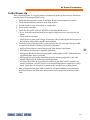
Code Blue Operation
The Code Blue feature provides a method of entering a high priority call at a floor. This feature
allows one of a specified group of cars to be called to a floor for priority service. Determining
which cars are eligible to respond is programmed at the job site using a hand held unit and may
range from one car to all cars. This operation is also known as Hospital Emergency Phase I and/
or Cardiac Arrest.
Recall Procedure
Upon activation of a Code Blue call input, the dispatcher will send the closest car available for
recall to the floor where the call was made. The dispatcher will select cars in the following order:
•
•
•
•
Cars on normal group operation
Cars on Simplex operation
Cars on Independent/Attendant (if enabled)
Cars on Fire Recall Phase I (if enabled)
Once selected, a car will flash the Code Blue Indicator, cancel all car and hall calls and proceed
non-stop to the Code Blue recall floor. Once at the floor, the corresponding door will open and
remain open for as long as the Code Blue button is activated plus the Code Blue wait time set.
(See Dispatcher Parameters Description below.)
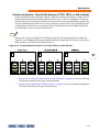
Dispatcher I/O
All Code Blue call inputs and outputs are located on the dispatcher.
They start at the next 8 call group after the last hall call and are located in order of bottom floor
to top floor, front door first, then rear door.
Car I/O
An indicator light must be connected to the Code Blue Indicator output. This
light will turn ON when the car is in Code Blue Recall operation or in Hospital Emergency operation.
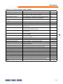
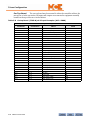
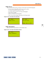
Car Parameters Description
The car group assignments table must be filled with a “Y” for every floor and door where the car
will answer Code Blue calls.
Floor Number (1 - 32)
Floor Designation
1-19
1
Tricon General Information
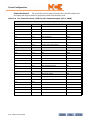
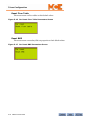
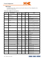
Dispatcher Parameters Description
The dispatcher floor table contains entries designated ‘CB’ for front and rear doors at every
floor. For every entry marked ‘Y’, a Code Blue call will be allocated. The first Code Blue call
defined will always be located at the first input of a hall call panel group. Hall calls and code
blue calls will never share the same hall card group panel.
Riser Number
Floor Number
Values
• Parameter ‘Code Blue: Override Fire Recall’ will enable the dispatcher to select a car for
Code Blue recall when it is on Fire Recall mode.
• Parameter ‘Code Blue: Wait Time’ will determine how long a car will sit at the Code Blue
recall floor waiting for the operator to activate the Hospital Emergency key switch. The
time is in seconds.
• Parameter ‘Code Blue: Override Independent and Attendant’ will enable the dispatcher to
select cars for Code Blue recall even when they are on Independent or Attendant service.
1-20 Manual # 42-02-2T00
Operating Modes
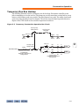
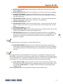
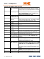
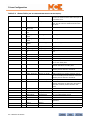
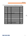
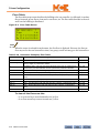
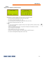
Seismic Operation
A “ring on a string” circuit is used to detect displacement of the counterweight caused by seismic activity (input CWS). The car position in the hoistway in relationship to the counterweight
is reported by a switch mounted on the car and positioned such that it is always closed when the
car is above the counterweight (input POS). The seismic switch is a manually activated switch or
an external seismic detection device (input SAS).
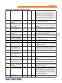
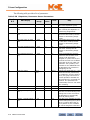
Car Setup Parameter 168 enables and disables seismic operation and also defines how the car
will operate on seismic or “earthquake” mode. If set to zero (0), seismic operation is disabled.
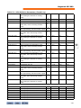
Other operating states are enabled by entering the sum of the desired Flag numbers into the
parameter. For example, to enable Flags 1, 2, and 4, you would enter a seven (7).
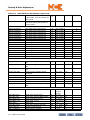
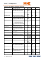
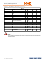
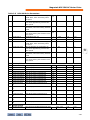
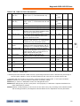
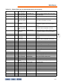
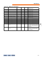
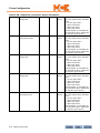
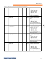
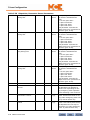
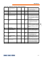
Table 1.2
Seismic Parameter 168 Settings
Flag
1
Enables
Seismic inputs and outputs on the EXT board are enabled according to ANSI A17.12000 code.
Active CWS input will cause an emergency stop after which the car will be in earthquake operation and will move to and level at the first available floor in the direction away from the counterweight and open its doors.
If CWS is off when the car is returned to a floor, it will return to Automatic service
at reduced speed. If CWS is continuously ON, the car will not return to service.
An active SAS input (alone) will cause the car to slow down and stop at the next
available floor. The car will then be returned to service at reduced speed.
A momentarily active SRE input will reset seismic operation provided both CWS and
SAS inputs are inactive.
2
When set, CWS or SAS inputs will return the car to a floor in a direction away from
the counterweight, open the doors for passenger exit, and remove the car from
service. If the CWS input is not continuously on, the following operations are
allowed at reduced speed:
Lobby Phase 1 fire recall.
Code Blue recall.
Code Blue car switch operation.
If the CWS input is ON, the car may only be run from the cartop inspection station.
4
If set, and the CWS input is continuously ON, the car will run at reduced speed in
response to a Lobby Phase 1 fire recall.
8
If set, and the CWS input is continuously ON, the car will run at reduced speed in
response to a Lobby Phase 1 fire recall only if the recall floor is above the counterweight position.
1
1-21
Tricon General Information
Seismic Input and Output Definitions
Please refer to “Seismic Equipment” on page 2-38 for additional explanation.
• CWS: Counterweight Displacement Switch input. Connected to a relay operated by the
counterweight displacement switch or to the switch directly. When triggered, the car will
make an emergency stop, then move to and level at the nearest floor in the direction away
from the counterweight. Once leveled, the car will open its doors and allow passengers to
exit. If the car is on Fire Phase 2, the doors will operate as defined for that mode.
• When in earthquake operation, the SAL (Seismic Activity Light) output will be
enabled.
• If on independent or attendant service, the BUZ (buzzer) output will be enabled until
the car is returned to a landing.
• SAS: Seismic Activity Switch input. Connected to a switch or seismic device. When triggered, a car in motion will drop all car and hall calls and proceed to the nearest landing.
Once leveled, the car will open its doors and allow passengers to exit. If the car is on Fire
Phase 2, the doors will operate as defined for that mode.
• When in earthquake operation, the SAL (Seismic Activity Light) output will be
enabled.
• If on independent or attendant service, the BUZ (buzzer) output will be enabled until
the car is returned to a landing.
• SRE: Seismic Reset input. Connected to momentary reset button. Resets earthquake operation provided SAS and CWS inputs are both OFF.
• POS: Counterweight Position Switch input. Connected to a switch mounted on the cartop
or hoistway positioned such that its contacts will be closed when the car is above the counterweight and open when the car is below the counterweight. This switch will retain its
state regardless of power status.
• SAL: Seismic Activity Light output. Connected to a warning light. Active when the car is on
earthquake operation.
• BUZ: Buzzer output. Connected to an audible signal. Active during earthquake operation if
the car is on independent or attendant operation until the car has been leveled to a floor
for five seconds.
1-22 Manual # 42-02-2T00
•
•
•
•
•
•
•
•
•
•
•
Installation
Install Sequence
Safety
Installation Considerations
Equipment Grounding
AC Power Connections
Motor and Brake Connections
Construction Operation
Completing Installation
Car to Group Wiring
Running on Inspection Mode
2
Installation
Installation
This section contains:
•
•
•
•
•
•
•
•
•
•
Install Sequence
Safety
Installation Considerations
Equipment Grounding
AC Power Connections
Motor and Brake Connections
Construction Operation
Completing Installation
Car to Group Wiring
Running on Inspection Mode
Note
If you have installed Tricon controls before, you might want to use the Tricon Quick Start Up
guide that came with the job prints.
2-1
Installation
Install Sequence
This is the installation sequence for installing and setting up Tricon controls:
•
•
•
•
•
•
•
•
•
•
•
•
•
•
•
Install and ground major system components (this section)
Connect AC power (this section)
Connect motor, brake, tach or encoder, velocity encoder, if used (this section)
Set up for Construction operation if needed (this section)
Complete installation of peripheral equipment, hoistway equipment, etc. (this section)
Complete field wiring (this section)
Controller parameter adjustments (Section 5)
Inspection start up (this section and drive information in Section 3)
Initial drive adjustments (Section 3)
Inspection speed learn operation (Section 4)
Inspection operation
Final tuning and drive adjustments (Section 3)
Normal speed learn operation (Section 4)
Final Testing (Section 4)
Release to operation
Supporting Information
The drawing package accompanying your controller provides information to make all connections and install all controller related components and is the primary guide to system
installation.
Section 5 of this manual contains parameter descriptions for all user-programmable system elements. The manual is intended to provide general knowledge of system components, system
operation, and supporting information for the controller drive (Section 3).
Please contact MCE support with any questions you have while installing and adjusting the Tricon system. If you discover errors, omissions, or incomplete information in this manual or in
the drawings package, please report them to MCE so that we can correct them.
2-2 Manual # 42-02-2T00
Safety
Safety
Keep safety in mind at all times to avoid injury or equipment damage.
Personal Safety
• Tricon controls should only be installed or maintained by qualified, licensed, elevator personnel familiar with the operation of microprocessor-based elevator controls.
• Verify that all safety devices (limits, governors, hoistway locks, car gate, etc.) are fully
functional before attempting to run the elevator. Never operate Tricon controls with any
safety device inoperative.
• The user is responsible for complying with current National Electrical Code with respect to
overall installation and for proper sizing of electrical conductors.
• The user is responsible for understanding and applying all current local, state, provincial,
and federal codes that govern controller placement, applicability, wiring protection, disconnections, over current protection, and grounding.
• Controller equipment is at line voltage when AC power is connected. Never operate Tricon
controls with covers removed from drive or brake controls.
• After AC power has been removed, internal capacitors can remain charged for up to 5 minutes. Wait at least 5 minutes after power down before touching any internal components.
• To lessen the risk of shock, all equipment must be securely grounded to earth ground with
a minimum of #8 AWG wire as outlined in the National Electrical Code. Failure to obtain
an actual earth ground may result in electrical shock to personnel.
• When using test equipment (oscilloscopes, etc.) with a power cord that electrically ties
probe common to earth ground, an isolation transformer should be used to isolate the
instrument common from earth ground.
• Stay clear of all rotating equipment while working on the controls.
Equipment Safety
• All equipment must be securely grounded to earth ground with a minimum of #8 AWG
wire as outlined in the National Electrical Code. Failure to obtain a true earth ground may
result in electrical shock and is the most common cause of electrical component failure
and noise-induced problems.
• Replace components only with main line power off. Damage to equipment or unexpected
operation of the elevator may occur if this precaution is not observed.
• Substitution of parts or unauthorized modifications should not be attempted before first
contacting Motion Control Engineering to ensure all safety features are maintained. MCE
will not be held responsible for circuit modifications made in the field unless they are
approved in writing by MCE.
• Circuit boards believed to be defective must be sent to MCE for repair and testing. Field
repair may leave the board with undetected problems.
• Care should be taken when using test leads and jumpers to avoid shorting high voltage or
ground to low voltage microprocessor circuits.
2-3
2
Installation
Installation Considerations
1. Dust, carbon, or metallic particles must not be allowed to accumulate on any part of the
control.
2. Avoid vibration and shock.
3. Avoid rapid temperature change, high humidity, high ambient temperatures.
4. Avoid caustic fumes.
5. Prevent electromagnetic interference. This may be caused by radio transmitters, high
voltage inductive spikes from unsuppressed relay coils, improper grounding, and
improper wiring practices. Note the following:
• The outer door will protect against interference only if closed. When the door is open,
do not run high wattage radios near the microprocessor.
• Noise from door operator reactors can cause a problem if mounted on the controller.
• If the CRT shows lines, spikes, or other signs of interference, check for electromagnetic
interference (noise) by checking the following:
• Proper grounding
• High voltage wiring running near the MPU board or monitor
• If seen when the door motor is operating (CX or OX are lit on the screen), add suppression around door operator circuitry.
• If seen when a relay is picking or dropping, add arc suppression around the coil.
Note
Standard arc suppressors (resistor/capacitor networks) are used on AC relays. Diode/resistor
combinations work well for DC relays. Consult MCE for proper component sizing.
Machine Room Preparation
When preparing the machine room for controller installation, consider:
• Equipment location
• Machine room environment
When choosing equipment location, consider:
• Adequate working space and a workbench or table.
• Logical arrangement, considering other equipment in the machine room and electrical
power.
• Do not install equipment in a hazardous location.
• A telephone in the machine room facilitates remote diagnostic and adjustment assistance.
• If any areas in the machine room are subject to vibration, they should be avoided or reinforced to prevent equipment damage.
• Provide adequate lighting.
• Reduce wiring by locating the isolation transformer near the controller.
2-4 Manual # 42-02-2T00
Installation Considerations
Environmental conditions are important:
• Ambient temperature should remain within 32 to 104 Fahrenheit (0 to 40 Celsius).
Temperatures outside these guidelines may be tolerated, but will shorten equipment life.
Adequate ventilation is required. Air conditioning may be necessary.
• The air in the machine room should be free of excessive dust, corrosive elements, and
excessive moisture. A NEMA 4 or NEMA 12 enclosure can help meet these requirements if
machine room conditions are inadequate. If the machine room has open or unglazed windows or other direct outside openings, place equipment cabinets far enough from them so
that severe weather does not damage the equipment.
• Very high levels of radio frequency (RF) radiation from nearby sources should be avoided.
RFI may interfere with controller components, degrading elevator performance. Using
hand-held communication devices close to the controller may also cause interference.
Interference from permanently installed radio transmitting antennas is not common.
• Power line fluctuation should not be greater than ±10%.
Piping and Wiring
Proper routing of signal and power wires is essential to microprocessor based equipment. Low
and high voltage wiring cannot be run in the same conduit, duct, or tray.
How Electrical Noise Occurs
Electrical noise may be induced when a high power conductor and a low signal level conductor
run alongside one another. As current flows through the high power wire, magnetic lines of flux
(voltage) expand outward and voltage is induced in the low level conductor.
The low level conductor, in the case of Tricon, may be a 24-volt input that really only needs to
see 12 volts to turn on. If the voltage induced from the high power conductor is large enough to
induce a 12-volt spike, the input can falsely turn on.
How to Avoid Electrical Noise Problems
Route high and low level signal wiring properly. Keep low level wiring in separate conduit from
high power wiring. If high and low power wiring must be run in the same duct, separate them by
a minimum of three to four inches. If one must cross the other, it should be at a ninety degree
angle.
Run low level wiring in shielded cable. The shield collects any induced voltage from surrounding high power wiring. The shield or “drain” must be connected to ground at one end only—
never at both ends.
2-5
2
Installation
Possible EMI/RFI Interference
Semiconductor devices that switch at high frequencies (such as variable frequency drives) produce EMI/RFI. To avoid EMI problems:
1. Run all motor leads in a separate conduit. Motor lead runs should be as short as possible. Control cabinet entry should be as close to the final termination point as possible.
2. Run main line supply leads in a separate conduit.
3. Run primary isolation transformer wiring in separate conduit from main line conductors to the transformer.
4. Run all secondary isolation transformer wiring in a separate conduit from the transformer to the drive cabinet.
5. A single-point ground should be established inside the control cabinet and a #8 AWG
ground wire run directly from each of the following devices to this single point:
• Earth Ground from running water supply, hydro-electric supplied ground, or a ground
supplied via an earthing rod to the single ground stud.
• Continuous wire from the main line disconnect to the single ground stud.
• Continuous wire from the motor frame to the single ground stud.
• Continuous wire from the isolation transformer frame to the single ground stud.
• Continuous wire from the line filter frame to the single-point ground stud.
• Jumper the “N” stud on the line filter to the line filter frame.
• Continuous wire from the load reactor frame to the single-point ground stud.
• Continuous wire from the drive frame ground stud to the single-point ground stud.
2-6 Manual # 42-02-2T00
Equipment Grounding
Equipment Grounding
A proper ground is essential to trouble free operation. Ground is defined as a direct connection
to EARTH GROUND. This type of ground is not always available from the electrical supply
panel.
The electrical conduit is not a sufficient ground for the system. Electrical ground should be
obtained and certified from the electrical contractor. If this is not available, keep the following
in mind when seeking an adequate connection to EARTH GROUND:
1. Building steel is not always earth ground. In most cases, building beams rest on concrete
beam pockets, and the earth connection is inadequate.
2. Sprinkler system water pipe is not adequate because the sprinkler system is, in most
cases, isolated from a free flowing earth water source.
If either of the two methods above are chosen for ground, and a true electrical ground is later
introduced to the system, a difference in potential can occur between the assumed ground and
the actual earth ground. This may lead to unsafe operating conditions and the possibility of
electrical shock to passengers or personnel.
3. A water pipe is an adequate ground only if the water in the pipe is connected to a continuous city water source.
Wiring Connections for Properly Grounded Systems
1. An uninterrupted ground wire of at least #8 AWG should be run from each car controller cabinet chassis or backplate to earth ground. The connection at the car controller
must be free of paint so the ground connection is made to the bare metal of the enclosure. The car controller should read less than 1-ohm to ground with the power off.
2. Ground straps, or short loops of ground wire, should be run from the controller ground
connection to the primary duct connections.
3. An uninterrupted #8 AWG ground wire should be run from the hoist motor frame to the
controller ground. The ground connection to the hoist motor must be free of paint.
4. A continuous looped ground wire should be run from each hall lantern and position fixture box to controller ground. The ground connection at each fixture should make an
electrical connection to the bare metal of the fixture box and its cover. This connection
should be free of paint.
5. An uninterrupted ground wire of minimum #14 AWG should be run from a termination
point on the cab to the controller ground.
6. An uninterrupted ground wire should be run from the cab enclosure to the ground terminal on the cab to protect passengers and personnel from electrical shock.
7. An uninterrupted ground wire should be run from each car operating panel to the
ground terminal on the cab to protect passengers and personnel from electrical shock.
8. An uninterrupted ground wire should be run from the dispatch cabinet chassis or backplate to earth ground. The connection at the dispatch cabinet must be free of paint so
the ground connection is made to the bare metal of the enclosure.
9. A continuous looped ground wire should be run from each hall push button station to
the dispatch or controller ground.
2-7
2
Installation
AC Power Connections
Note
All conductors entering or leaving the controller must be through conduit. High voltage, high
current conductors must be separated from control wires. Velocity encoder or tachometer wires
must be routed in a separate conduit from high voltage, high current wires. Incoming power to
the controller and outgoing power to the motor must be through separate, grounded conduits.
Brake Module
If your job uses a brake control module, your job drawings may show auxiliary power connections specific to the brake from an isolation transformer. Follow the drawings carefully.
1. Check the AC input specifications on your job prints. Verify that the AC supply is as
specified.
Note
Proper motor branch circuit protection in the form of a fused disconnect switch or circuit
breaker must be provided for each elevator according to applicable electrical code. Each disconnect or breaker must be clearly labeled with the elevator number. The electrical contractor must
determine the wire size for the main AC power supply and for the wiring from the disconnect or
breaker to the controller or isolation transformer.
2. Connect AC supply wiring as shown in the job prints.
2-8 Manual # 42-02-2T00
AC Power Connections
Initial Power Up
After connecting power, it is a good practice to temporarily power up the control to check functionality before connecting any field wiring.
1.
2.
3.
4.
5.
Verify that the Inspection switch on the Relay Board is in the Inspection position.
Verify that the Run/Stop switch is in the Stop position.
Visually check for loose connections or components.
Power up the controller.
Check that the 24VDC and 110VDC LEDs on the Relay Board are on.
• If not, verify all transformer and power supply voltage levels are correct per the job
prints.
• Verify all fuses are intact.
• Check phase-to-phase input voltage. If necessary, shut off main power and swap two of
the incoming feeds at the controller main terminal.
6. Check the status of the three LEDs on the top left of the I/O 24 boards. The green LED
on each board should be blinking. See below if otherwise:
• Solid red: Board has not started up properly. May indicate a bad board.
• Solid amber: Board has not completed initializing.
• Solid green: Board has started properly and is sending data to MPU. LED should starting blinking after about 15 seconds.
• Solid green with solid amber: Board has incorrect system configuration. (All other
boards will probably be indicating normal operation.)
• No LEDs: Check that the four-pin power cable from the PW5 board is properly connected. Check that 5-volt DC power is at all red and black power connections on PW5
board. Check that 110-volt power is present at IP1 and IP2 fuses on Relay Board.
7. After verifying that the green LED on each I/O 24 board is blinking or correcting the
problem if they are not, shut down the controller before continuing with field connections.
2-9
2
Installation
Motor, Brake, and Encoder Connection
Danger
Verify that power to the controller has been shut off at the main disconnect before proceeding with connections.
Motor Connection
If you are reusing an existing hoist motor, you must check it for insulation breakdown before
proceeding.
Insulation Breakdown Test
1. Disconnect all motor and brake wiring.
2. Perform an insulation test between motor and brake connection points and the body of
the motor. Use a Megohm meter to subject the insulation to the same high voltage that
would be present during elevator operation.
3. A minimum insulation resistance of 100k Ohms is required.
4. Correct any insulation problems before proceeding with installation. Insulation problems may indicate a serious problem in the equipment.
Motor Wiring
Incoming power to the controller and outgoing power wires to the motor must be through separate grounded conduits.
1. Refer to the Power section drawing in your job prints.
2. Make connections as shown. Be sure to follow any notes regarding wire sizes.
Brake Connection
1. Refer to the brake circuit drawing in your job prints to verify the configuration of the
braking circuit. (Brake control and brake adjustment resistors vary from job to job.)
2. Connect the wires from the controller to the brake as shown in the job prints. Remember
that brake wires must not be routed in the same conduit with motor power or velocity
encoder wires.
Brake Mechanics
Check basic brake characteristics at this time:
• Ensure that the brake mechanism is clean and in good condition.
• Check that the brake lining makes good contact with the machine braking surface (at least
95% of the pad must be in contact with the braking surface).
• Check that the adjustment of the brake solenoid is not preventing the brake from fully
applying when it is not energized.
• If you have the manufacturer recommended brake torque settings, check to see that the
spring adjustments are equal and are torqued to at least that setting.
2-10 Manual # 42-02-2T00
Motor, Brake, and Encoder Connection
Velocity Encoder Installation and Wiring
The velocity encoder reports hoist motor speed to the controller. The encoder must be mounted
and wired according to the drawings. When installed, the encoder must be electrically isolated
from the motor or any other ground. (Resistance between the encoder casing and the motor or
other ground should be “infinite.”)
Do not place the encoder or its wiring close to a magnetic field (the motor or brake coils). Magnetic fields can induce AC into the encoder signal. This can cause the drive to miscount, producing erratic control at lower speeds.
Note
The encoder wiring must use a separate grounded conduit. Inside the controller cabinet, if control wires must cross power wires, they must cross at right angles to reduce the possibility of
interference.
Encoder Mounting
The following illustration shows two typical encoder installations.
Figure 2.1
2
Typical Encoder Installations
Typical mounting
bracket
Hoist motor
9-pin D
Connector
Velocity
Encoder
Hoist motor shaft
Flexible coupling
Hoist motor
shaft
Isolator
bushing
Phenolic
isolator
Velocity Encoder
2-11
Installation
It is very important that the encoder does not slip, wobble, bounce, or vibrate due to poor installation of the shaft extension, coupling, or encoder mounting. It is also important that the
encoder housing be electrically insulated from the motor, machine or other grounds if the
encoder is manufactured by BEI. An insulated encoder mount has been furnished with the BEI
encoder. However, this type of mounting may not be practical for all applications, therefore, the
best method for mounting the encoder and coupling it to the motor must be determined at the
job site.
Encoder Isolation
The encoder housing must be electrically isolated from the machine (ground). To check this:
1. Measure the resistance between the encoder case and the frame of the motor.
The measured value must be “infinite” for complete isolation.
Encoder Wiring
A shielded cable with an appropriate connector at the encoder end is provided. The controller
end of the cable exposes trimmed and tinned individual conductors. The encoder cable must be
routed into the controller cabinet in a separate conduit. Connect the cable to the encoder using
the cable/connector provided.
1. Route the cable through a separate conduit to the controller cabinet.
2. Connect the controller end of the cable as shown on the Drive Interface sheet of the job
prints.
3. Verify that the encoder shield is soldered to the drain wire (wire without insulation).
Keep the cable shield connection as short as possible.
Caution
Do not coil excess Encoder cable near high voltage components — noise may be induced. If
the cable must be shortened, trim it at the controller end. Do not cut and re-splice in the
middle of the cable or shorten at the Encoder end.
2-12 Manual # 42-02-2T00
Motor, Brake, and Encoder Connection
T-Limit-2K Motor Speed/Position Sensor
For A17.1-2000, CSA B44.00 compliant controllers, a speed/position sensor mounted on the
elevator machine/motor provides independent feedback to the T-Limit-2K Limit/Gripper
board through a special cable assembly. This connection is detailed on the Limit/Rope Gripper
Board drawing in the drawings package accompanying the controller.
The speed sensor detects a magnet assembly, attached to the shaft of the motor, as the magnet
assembly passes during each motor revolution.
Mounting the Magnet Assembly
DO NOT drill any holes in the motor shaft to mount the assembly. Use hose clamps as shown in
the following illustration.
Figure 2.2
Mounting the Speed Sensor Magnet Assembly
End View
Side View
Magnet
Magnetic
Shunt
(Iron)
2
Aluminum
Base
Motor Shaft
Hose Clamp
2-13
Installation
Mounting the Speed Sensor
When mounting the speed sensor, do not over-tighten the mounting nuts. Position the face of
the sensor so there is 1/16” to 1/8” (1.6 - 3.18mm) clearance between the face of the sensor and
the magnet assembly. The speed sensor must be electrically isolated from the motor body. The
sensor is provided with the proper mounting hardware.
Figure 2.3
Speed Sensor Mounting (side view)
Sensor housing
Magnet Assy.
Motor shaft
The slot in the housing allows the
sensor to magnet distance to be
adjusted.
Figure 2.4
Speed Sensor Mounting (top view)
If the motor bolt is 1/2-inch, a
spacer (large locknut washer)
is used in the mounting hole to
keep the mounting bracket
centered. (spacer included)
Motor shaft
Mounting bracket
Various size spacers are provided
so you can center the sensor over
the magnet.
Sensor housing
2-14 Manual # 42-02-2T00
Magnet
Assy.
Construction Operation
Construction Operation
If required, it is possible to run the car during construction without all hoistway limits, door,
and gate switches in place. In this mode, the car runs at inspection speed (45 fpm). If they are in
place cartop controls may be used or the car may be run from the controller. If desired a temporary run box may be installed.
Minimal Requirements
Minimal equipment requirements are:
• The governor must be wired into the Safety string.
• If needed, a temporary controller box may be connected. Please refer to “Temporary Run
Box Hookup” on page 2-17.
• Motor, brake, and drive connected and set up
• Velocity encoder or tach if used
• Normal and Final Limit Switches installed and connected
Jumper Requirements
Temporary jumpers, as necessary, may be placed across the following connections in order to
run the car on construction inspection. PMT designates a panel mounted terminal connector
like those typically used for brake connections.
Table 2.1
Construction Mode Jumper Requirements
Bypassed Functions
Jumper Connections
Governor 110%Overspeed
GOV1 (RB, TB1-3 to GOV1A (TB1 on PMT)
N/A on non 2k models
Hoistway safety string
GOV1 (RB, TB1-3 to CG1 (RB, TB3-5)
Car Gate
CG1 (RB, TB3-5) to CG2 (RB, TB3-6)
Door Lock
TL1 (RB, TB4-2) to BL2 (RB, TB4-7)
Up Normal Terminal
UNT1 (RB, TB4-8) to UNT2 (HY-1)
Down Normal Terminal
DNT1 (HY-2) to DNT2 (HY-3)
Door Pre-Lock
PL1 (RB, TB3-7) to PL2 (TB3-8) (Factory jumpered if no door pre-locks)
Required Controller and Drive Parameter Settings
In order to operate safely in construction mode, particular controller and drive parameters
must be verified or set.
Caution
Before powering the controller to make these settings, verify that the Run/Stop switch is in
the Stop position.
2-15
2
Installation
Controller Parameters
The Hand Held Unit (HHU) is used to program controller parameters. Refer to Section 6 of this
guide if you are unfamiliar with the operating the HHU. For the settings described here, you
may plug the HHU into the jack on any of the I/O 24 boards in the controller.
• Car Setup/Parameters Menu
• Parameter 76: Time to hold the drive running after the brake output is dropped during
Inspection operation. Slow brake compensation. Start with 2.0 seconds; adjust as
needed.
• Parameter 84: Time to delay brake lift during Inspection operation. Set to compensate
for potential roll back. Machine dependent.
• Parameter 85: Time brake remains lifted after the car stops during Inspection operation. Set to 0.0 seconds.
• Parameter 106: Pattern start delay during Inspection operation. Set to 0.0 seconds.
• Parameter 125: Enable gate and lock bypass switches on RB board. Set to Yes.
• Parameter 128: Allow construction inspection with bypass switches. Set to Yes.
• Parameter 132: Inspection High Speed. Set to Yes to run at 45 FPM.
• Parameter 162: Enable Redundant Inspection Check. Set to No.
Drive Parameters
Drive parameters are set on the drive. Locate the start up instructions for your drive and feedback loop in this manual (Section 4) and set parameters accordingly. Consult the drive manufacturer’s manual to familiarize yourself with the drive.
Danger
Set the Inspection Speed parameter of the drive to 45 FPM.
Using Inspection Stations to Run
In inspection, a car operates at slow speed using up and down buttons. The car will stop as soon
as the buttons are released.
Controller
Operate the car using the controller UP or DOWN
inspection buttons. A car running in either direction will
automatically stop when it reaches the normal terminal
switch in that direction. Pressing and holding both UP
and DOWN buttons at the same time will open the doors
if the car is stopped at a door zone.
Car Top Inspection
In this mode, the car is operated by pushing the cartop
UP or DOWN and SAFETY buttons. Doors will open if
both UP and DOWN buttons are pressed for more than
two seconds while the car is in a door zone.
2-16 Manual # 42-02-2T00
Construction Operation
Temporary Run Box Hookup
The following illustration shows a temporary run box hookup. Disconnect controller power
before attempting to wire the run box. The temporary run box must have a safety button, an up
button, a down button, and a stop switch. The safety button is two-pole. The safety circuit must
open every time the safety button is released. The run box uses the same inspection direction
inputs on the CTRL board as the controller inspection circuit does.
Figure 2.5
Temporary Construction Operation Run Circuit
Car top insp.
safety button
Car Top Insp.
Stop Sw.
GOV1 Governor
GOV2
TF1
RB
TB1-3
RB
TB1-4
RB
TB1-5
UP
2
Car top insp.
safety button
Insp. up
RB
COM
RB-TB5-P24B
RB
Construction
Inspection Terminal on
Relay Board
Insp. down
DN
2
2
RB CTRL
A1
A1
3
3
CIUB
CIDB
RB
RB CTRL
A1
A1
Construction
Inspection Terminal on
Relay Board
2-17
Installation
Running the Car
1. On the controller Relay Board:
• Set the Inspection switch UP.
• Set the Stop switch DOWN.
2. Power up the controller.
3. Attempt to run the car up using the inspection up/down buttons. Hold the up button
until the car starts to move. If the motor moves in the down direction, stop the car.
Change the motor rotation setting on the drive or temporarily disconnect power and
swap two of the input phases to the motor.
4. Again run the motor. Confirm that the motor turns in the correct direction to move the
car up or down.
5. Check the speed reference on the drive. Run the car in the down direction. The speed
reference displayed on the drive should be negative. Using the inspection up button, run
the car in the up direction. The speed reference should be positive.
6. While using the inspection up/down buttons to run the car, use a hand tach to check car
speed. It should be moving at approximately the same speed as that displayed by the
drive. This should be very close to 45 FPM. Adjust drive inspection speed setting if
required.
Brake Basics
1. Ensure that the brake is picking cleanly.
2. Ensure that, when set, the brake is capable of holding 125% of rated car capacity.
3. Check that brake and motor coordination are such that the brake is dropping just when
motor rotation stops.
4. Check that the brake pick delay allows the motor to build sufficient flux to prevent roll
back when the car is starting.
2-18 Manual # 42-02-2T00
Completing Installation
Completing Installation
If the car has been operated in Construction mode, temporary jumpers may have been used to
bypass some safety string or other connections. As you are completing field wiring for the car,
be certain to remove any temporary jumpers.
The drawings package for your specific job contains all the information to complete remaining
hoistway, car, and field wiring. Hoistway limit switches and floor leveling and slowdown magnet placement specific to your job are also in the drawings package.
The remainder of this topic contains:
• A description of the I/O 24 boards and terminal boards used for low voltage field inputs
and outputs.
• Basic brake checks.
• Inspection Learn for Limit Board.
• A description of the landing system and hoistway tape/magnets used by Tricon systems.
• A description of the limit and slowdown switches used by Tricon systems.
• A description of Seismic detection equipment
Read these to familiarize yourself with the equipment but follow the specific instructions contained in your drawings package for installation purposes.
2-19
2
Installation
Low Voltage Signal Wiring
Low voltage signal wiring includes all the 24-volt inputs. These include car calls, door limits,
electric eyes, etc. The inputs on the I/O boards only need to see 12 volts or more to turn on. If
the signal wires are run along side the 240 VDC door operator wiring, a 12-volt spike is very
likely to occur. Keep low level signal wiring at least 4 inches from high power wiring to avoid
false signal firing. If this is not possible, and the low level wiring must cross the high power wiring, the two should cross at a ninety-degree angle.
Terminal boards, mounted on I/O 24 boards, are used for low voltage connections. The function of the particular I/O 24 board/Terminal board set is determined by the software installed
on that I/O 24 board. Each I/O 24 board is labeled according to its function or location. For
example, the I/O 24 board used in the car station is labeled “CSTA” while the I/O 24 used for
hall call connections in the controller cabinet is labeled “HALL.”
Figure 2.6
I/O 24 Board Layout
Software installed in this
chip determines function of
board and terminal boards.
Terminal board locations
In the wiring prints, inputs and output labeling will tell you where the terminal board to be used
is located using the I/O24 board label (i.e., CSTA), the Terminal board position (i.e., A), the
Terminal board type (i.e., F) and the connector pin number. For example: CSTA-AF 28 means
pin #28 on the F Type terminal board in the A position on the CSTA (I/O24) board.
2-20 Manual # 42-02-2T00
Completing Installation
Three Terminal boards are most commonly used for low voltage signal wiring:
• F Type Terminal Board
• O Type Terminal Board
• L Type Terminal Board
F Type Terminal Board
The F Type Terminal board provides 8 single-wire inputs and 8 two-wire (+V/GND) outputs.
The wiring prints for the job will detail how each input and output must be connected.
Figure 2.7
F Type Terminal Board Connections
2
2-21
Installation
O Type Terminal Board
The O Type Terminal board provides 8 single-wire inputs and 8 “single-wire” outputs that share
a common voltage connection. The common voltage is determined by a connection to a voltage
source on the Relay Board.
Figure 2.8
O Type Terminal Board Connections
2-22 Manual # 42-02-2T00
Completing Installation
L Type Terminal Board
The L Type Terminal board provides 8-inputs and 8-outputs working together. For example,
after an input is detected, the same connection becomes an output to drive the indicator bulb
for that input. L Type Terminal boards are used for Car and Hall Call connections.
Figure 2.9
L Type Terminal Board Connections
2
2-23
Installation
SET-9000 Landing System
The SET-9000 landing system uses solid state sensors to detect the presence of magnetic strips
placed on a length of 2-inch steel tape that runs the length of the elevator hoistway. Magnetic
strips are placed along the tape in three, distinct rows. The center row is used for “leveling”
magnets. The left hand row is used for up direction “slowdown” magnets. The right hand row is
used for down direction “slowdown” magnets.
The sensor head containing the solid state sensors is mounted on the elevator car so that it
“rides” the steel tape as the car moves, detecting and using the magnets to control floor
approach and leveling.
Installing the SET-9000 system includes:
•
•
•
•
•
Hoistway tape installation
Interconnect box installation
Sensor head installation
Magnetic strip placement
Landing system cabling
Figure 2.10
SET-9000 Landing System Components
2-24 Manual # 42-02-2T00
Completing Installation
Hoistway Tape Installation
The SET-9000 system uses 2-inch wide steel tape. The tape is hung from a bracket at the top of
the hoistway in a single, vertical run to a second bracket at the bottom of the hoistway. The bottom bracket has a tensioning spring that is adjusted to maintain tension on the tape, preventing
undue movement and possible noise from tape vibration. Tape installation includes:
• Top bracket and hanger installation
• Bottom bracket and tensioner installation
Before installing stationary tape, ensure the location you choose will have adequate clearance
from shaft-way beams, walls, counterweights, cab, and terminal limit cams. Make sure the SET9000 is not placed too close to the governor lift arm so that, when the car safeties are activated,
the sensor assembly might be damaged or the car safeties prevented from working properly.
Top Bracket and Hanger Installation
1. Run the car up the hoistway on Inspection mode until the counterweight is resting on a
fully compressed buffer.
2. Using the clips provided, attach the top bracket to the back of the elevator guide rail as
shown below. The bracket should be installed to position the steel tape as close to the car
sling as the guide shoe and hoistway equipment clearance will allow.
Figure 2.11
Top Tape Bracket Installation
3. Bolt the upper tape hanger assembly to the bracket at the chosen location.
4. Referring to the figure above, push the end of the steel tape through the bottom of the
tape hanger clamp.
5. Loop the tape as shown and again insert the end through the tape hanger clamp, allowing about 1-inch to protrude above the clamp.
6. Tighten the clamp bolts.
7. Run the car down the hoistway on Inspection. Slowly play out the steel tape as you go.
2-25
2
Installation
Bottom Bracket and Tensioner Installation
The tape should be attached in the
pit low enough so that, when the car is on the fully compressed buffer, the stick and any car
devices do not come in contact with the tape hold down assembly.
1. Using the clips provided, attach the bottom bracket to the back of the guide rail as
shown below. The bracket should be about 6-inches below the lowest floor level and
must be square to the guide rail.
Figure 2.12
Bottom Tape Bracket Installation
2. Loosen the nuts on the spring tension bolt until only two threads are showing.
3. Remove the tape hanger clamp.
4. Slowly run the car down until the buffer is fully compressed. Check that there is sufficient clearance between the car and the lower rail bracket.
5. Position the steel tape against the lower tape hanger and reinstall the clamp to hold the
tape in position. Tighten the clamp bolts ONLY LIGHTLY.
6. Cut the steel tape one foot below the clamp bottom.
7. Loop the steel tape and insert the end through the clamp so that about 1-inch protrudes
from the clamp bottom. Tighten the clamp bolts securely.
8. Adjust the spring tensioning nut to provide adequate tensioning of the tape in the hoistway. Use the second (double) nut to insure the first nut is unable to loosen.
9. During installation, the edges of the tape may be gouged. After tape installation is complete, go over the tape edges with a fine file to remove any burrs or gouges. This will
ensure quiet operation of the SET 9000 system as the car travels at contract speed.
10. After smoothing the tape edges, wipe off all excess oil and dirt from the face of the tape
so that the magnets will stick properly when they are installed later. Do not use rags that
leave lint on the tape during cleaning.
2-26 Manual # 42-02-2T00
Completing Installation
Interconnect Box Installation
The interconnect box contains the electronics that interpret the landing sensor inputs for the
car controller. Depending on your installation requirements, you may have one of two interconnect boxes.
• Cartop Station: Most installations use a cartop station containing not only the board that
connects to the landing sensor but boards performing other functions as well.
• Control Box: In some installations, there is a
requirement that the microprocessor and door
controller electronics that are normally in the
cartop station, be located in the Tricon elevator
control cabinet instead. In these cases, a smaller
interconnect box, the control box, is used in
place of the cartop station. Figure 2.1 earlier in
this section shows an installation using the control box (actual unit shown to the right).
Regardless of the interconnect box type used, mount
it in a secure location on the elevator crosshead close
enough to the landing sensor head to connect the two
with the cable provided.
Sensor Head Installation
Please refer to “SET-9000 Landing System Components” on page 2-24. Sensor head installation consists of installing the crosshead bracket, the adaptor bracket, and the sensor head
assembly. The sensor head assembly mounts to the adaptor bracket via a “floating” subassembly that allows the sensor head to move with tape or hoistway irregularities. Tape guides at each
end of the sensor assembly “grip” the hoistway tape and keep the sensors at the correct distance
from the strip magnets.
Figure 2.13
Sensor Head Assembly
Tape guide
“Floating” bracket
subassembly
2-27
2
Installation
1. Clip the crosshead bracket to the crosshead. Check that the bracket is square with the
crosshead.
2. Bolt the adaptor bracket to the crosshead bracket. Check that the adaptor bracket is
square with the crosshead bracket.
3. Slide the sensor head mounting subassembly onto the adaptor bracket.
4. Remove the screws that hold the tape guide outer end caps in place and remove the caps.
Figure 2.14
Tape Guides
Tape Guide (closed)
Tape Guide (open)
5. Position the sensor head assembly on the steel tape.
6. Replace the tape guide caps. Reinsert the
screws.
7. Bolt the sensor head assembly to the subassembly. Adjust the mounting bracket and
secure.
8. Connect the sensor head assembly to the
interconnect box using the supplied cable.
9. If needed, adjust the sensor assembly so it
does not ride hard on one side of the unistrut bracket during any part of the travel
through the hoistway.
2-28 Manual # 42-02-2T00
Completing Installation
Magnet Installation
• The floor leveling and slowdown magnetic strips are 6-inches long.
• Install all floor leveling magnets before installing one-floor-run up, high-speed up, onefloor-run down, and high-speed down magnets.
• Two speed operation requires leveling, one-floor-run up, and one-floor run down magnets
only.
• Three speed operation requires leveling, one-floor-run up, one-floor-run down, highspeed up, and high-speed down magnets.
• Selective installations (front and rear car doors) require, in addition to the appropriate
two-speed or three-speed operation magnets, front and rear door zone magnets. Door
zone magnets are placed to the left (front door zone) and right (rear door zone) of the leveling magnet.
Consistent measurement is the key to good installation. Cut a stick to the slowdown distance
required for the job, and use it to install all one-floor-run magnets. (For three-speed jobs, cut a
second stick for the high-speed magnets.) This will ensure consistent slowdown targets. Even if
the targets are installed at an incorrect distance (by up to 2 inches), the speed board (in most
cases) may be adjusted to accommodate.
• Floor leveling magnets are placed in the center of the tape.
• Up slowdown magnets are placed on the left side of the tape.
• Down slowdown magnets are placed on the right side of the tape.
2-29
2
Installation
Leveling Magnet Installation
A row guide and a level guide are provided to help with magnet installation.
• The row guide is a five-inch long
by 2-inch wide magnetic “block”
with markings indicating magnet row location on the 2-inch
tape.
• The level guide is a nine-inch
long magnetic strip used to
position the floor level magnets
vertically.
1. Bring the car to floor level.
Place the row guide across the
top of the sensor head.
2. Move the elevator down.
Place the (9-inch) level guide
strip vertically under the center of the row guide.
2-30 Manual # 42-02-2T00
Completing Installation
3. Use the row guide to locate the leveling row (typically row 2/center row, but check your
job prints to be certain). Remove the backing from a leveling magnet strip and place it
carefully in the correct row just under the level guide magnet.
2
4. Repeat these steps for each floor in the building.
2-31
Installation
Slowdown Magnets
One-floor-run up and down magnets are required on all jobs. The distance from floor level (center of the leveling magnet) to the top of a down slowdown magnet or to the bottom of an up
slowdown magnet is called the “slowdown distance.” Magnet placement instructions for your
particular job are in the job print package provided. The following descriptions are general
guidelines only.
No High Speed Operation, Front Doors ONLY
For jobs not requiring high speed
operation, slowdown distance is typically one foot of slowdown for every 50 FPM of contract
speed OR the shortest floor height divided by 2.5 — whichever is smaller. The table below provides slowdown distances for non-high speed operation. This distance may need to be adjusted
depending on the rotating equipment used.
• One-floor run speeds are typically under 200 FPM with 8' 6" floors
Speed
Slowdown Distance
50 FPM
100 FPM
125 FPM
150 FPM
175 FPM
200 FPM
1'
2'
2'
3'
3'
4'
0"
0"
6"
0"
6"
0"
Min Floor Height
2'
4'
5'
6'
7'
8'
6"
6"
6"
6"
6"
6"
Magnet placement:
• For Up Slowdowns - Measurement is from the center of the leveling magnet to the bottom edge of the
slowdown magnet.
• For Down Slowdowns - Measurement is from the
center of the leveling magnet to the top edge of the
slowdown magnet.
2-32 Manual # 42-02-2T00
Completing Installation
No High Speed Operation, Front & Rear Doors
rear doors, two additional magnets are required per floor:
When a car has both front and
• Front door zone magnet: For each floor, a front door zone magnet is placed in tape row 1,
immediately to the left of the floor level magnet.
• Rear door zone magnet: For each floor, a rear door zone magnet is placed in tape row 3,
immediately to the right of the floor level magnet.
2
1. Install a door zone magnet for each door opening in its corresponding location. If there
are two openings at a floor, install both door zone magnets.
Note
Door zone magnets are SOUTH POLE. These are only used for jobs with Front AND Rear door
openings.
2-33
Installation
High Speed Operation, Front Door ONLY
High speed operation requires four
slowdown magnets per floor, one-floor up and down magnets, plus high speed up and down
magnets. One-floor magnet slowdown distance is calculated to be the shortest floor height in
the building divided by 2.5. High speed magnet slowdown distance is equal to the top speed of
the car divided by 50.
Speed
250
275
300
325
350
375
400
FPM
FPM
FPM
FPM
FPM
FPM
FPM
High Speed Magnet Slowdown
Minimum Floor Height
5'0"
5'6"
6'0"
6'6"
7'0"
7'6"
8'0"
6'6"
7'
7'6"
8'
8'6"
9'
9'6"
The slowdown distances are based on the magnets being placed as follows:
• For Up Slowdowns - Measurement is from the center of the leveling magnet to the bottom
edge of the slowdown magnet.
• For Down Slowdowns - Measurement is from the center of the leveling magnet to the top
edge of the slowdown magnet.
2-34 Manual # 42-02-2T00
Completing Installation
High Speed Operation, Front & Rear Doors
doors, two additional magnets are required per floor:
When a car has both front and rear
• Front door zone magnet: For each floor, a front door zone magnet is placed in tape row 1,
immediately to the left of the floor level magnet.
• Rear door zone magnet: For each floor, a rear door zone magnet is placed in tape row 3,
immediately to the right of the floor level magnet.
2
1. Install a door zone magnet for each door opening in its corresponding location. If there
are two openings at a floor, install both door zone magnets.
• Door zone magnets are SOUTH POLE. Used ONLY on jobs with Front AND Rear openings.
Landing System Cabling
Wire the cartop interconnect box as described in your job prints.
• Relay outputs are dry contact, 1 amp, N.O.
2-35
Installation
Limit and Slowdown Switches
The limit and slowdown switch arrangement for your particular job is described in the job
prints.
Generally, for car speeds under 200 feet per minute (CTRL No.1 software):
• Normal Limit: The normal directional limits should be set open when the car is 1.5" before
floor level at the terminal floors.
• Final Limit: The final limits should be set to open no sooner than 6" beyond the floor.
• Top Terminal Slowdown: The slowdown switch should be set to open immediately AFTER
the US sensor comes on the top floor slowdown magnet. (This can be seen by monitoring
the US relay on the SET9000 sensor interface board. LED D3 lights.) This slowdown
switch opens U1S1 to U1S2.
• Bottom: The slowdown switch should be set to open immediately AFTER the DS sensor
comes on the bottom floor slowdown magnet. (This can be seen by monitoring the DS
relay on the SET9000 sensor interface board. LED D4 lights.) This slowdown switch opens
D1S1 to D1S2.
Generally, for car speeds over 200 feet per minute (CTRL No.2 software):
• Top Switch 1: The terminal slowdown switch that is furthest from the floor should be set to
open immediately AFTER the US sensor comes on the top floor high speed slowdown
magnet. (This can be seen by monitoring the HU relay on the SET9000 sensor interface
board. LED D3 lights.) This slowdown switch opens U2S1 to U2S2.
• Top Switch 2: The terminal slowdown switch that is closest to the floor should be set to
open immediately AFTER the US sensor comes on the top floor one floor run slowdown
magnet. (This can be seen by monitoring the HU relay on the SET9000 sensor interface
board. LED D3 lights.) This slowdown switch opens U1S1 to U1S2.
• Bottom Switch 1: The terminal slowdown switch that is furthest from the floor should be
set to open immediately AFTER the DS sensor comes on the bottom floor high speed slowdown magnet. (This can be seen by monitoring the DS relay on the SET9000 sensor interface board. LED D4 lights.) This slowdown switch opens D2S1 to D2S2.
• Bottom Switch 2: The terminal slowdown switch that is closest to the floor should be set to
open immediately AFTER the DS sensor comes on the bottom floor one floor run slowdown magnet. (This can be seen by monitoring the DS relay on the SET9000 sensor interface board. LED D4 lights.) This slowdown switch opens D1S1 to D1S2.
2-36 Manual # 42-02-2T00
Completing Installation
Figure 2.15
Hoistway Switch Opening Electrically Correlated to Magnet Positions
Final Limit
Floor level, + 6-inches
Normal Limit
Floor level, - 1.5-inches
Slow Down
High Speed Slowdown
Floor Level Magnet
One Floor Run Up Magnet
High Speed Up Magnet
CTRL No. 2 Software
High Speed
> 200 FPM ONLY
2
In-between Floor Level Magnets
High Speed Slowdown
CTRL No. 2 Software
High Speed Down Magnet High Speed
> 200 FPM ONLY
Slow Down
One Floor Run Down Magnet
Normal Limit
Floor level, + 1.5-inches
LED D2
Board power indicator
Floor Level Magnet
Final Limit
Floor level, - 6-inches
LED D3
LED D4
LANDING SYSTEM SENSOR INTERFACE BOARD
2-37
Installation
Seismic Equipment
A “ring on a string” circuit detects excessive counterweight motion caused by a seismic disturbance. When motion is detected, the car will make an emergency stop. After stopping, the car
will move to and level at the next available floor in the direction away from the counterweight.
After leveling, the car will open its doors and allow passengers to exit.
Modes of operation other than Automatic, for example Fire Phase II or attendant mode, allow
different operating options. Please refer to Seismic Operation on page 1-21. The following illustration is an example of wiring connections for seismic equipment. Your system may be different so always follow the print in the wiring diagrams specific to your job.
Figure 2.16
Seismic Device Connections
Seismic Switches
RB-GND
RB-TB5-P24
P24
GND
RSD
1N4004
CW1
CW2
14
RS
13
150 ohm 10 W
Counter weight
RS
RS will be energized normally
1
9
CWS
1
EXT1
CF
Counter Weight
Displacement
2
Seismic Switch
SAS
EXT1
CF
The reset switch is typ-
3
SRE
Seismic Reset Switch ically a momentary
POS
Counterweight position switch
switch is closed when the car is
above the counterweights
EXT1
CF
Counterweight position switch
4
EXT1
CF
SAL
9
SAL
5
contact pushbutton.
Seismic Activity Light
SALD
1N4004
SAL
23
24
EXT1
AF
EXT1
AF
2-38 Manual # 42-02-2T00
14
SAL
13
Car to Group Wiring
Car to Group Wiring
Car controllers communicate with the group dispatcher through high-speed, twisted-pair, network connections. Communication cables (white shielded wire) between the cars and the dispatcher should be run in a separate pipe from all other signal wiring.
When a car is part of a group, an additional circuit board (the Gateway board) is used. In most
applications, a Gateway board is mounted in each car cabinet. In some jurisdictions (NYCHA
for example), all Gateway boards for all cars in a group are mounted in the group dispatcher
cabinet. In both instances, drawings in the job drawing package detail the appropriate connections. The following drawings provide examples of both types of interconnection.
Figure 2.17
Car / Group Communication, Standard Implementation
2
Alternatively, a separate
twisted pair may be used for
each car.
2-39
Installation
Figure 2.18
Car / Group Communication, Alternate Configuration (NYCHA)
2-40 Manual # 42-02-2T00
Running on Inspection Mode
Running on Inspection Mode
Danger
Controller inspection warnings:
• Read Sections 1 and 2 completely before starting this procedure.
• Have someone stand by the main line disconnect during the following phases of the start
up procedure for added safety:
• First time power is applied to the controller
• First time an attempt is made to move the car
• Insure all safety circuits are functional.
• Insure all hoistway door interlocks are functional.
• Insure car gate circuitry is functional.
Prior to Applying Power:
• Verify all circuits are wired to the controller properly.
• Check the following items:
• INSP switch up
• STOP switch down
• Door Disconnect up
• Verify, with an ohmmeter, that the governor overspeed switch and any other devices that
are wired in at this time will open the safety circuit.
• Physically verify that all hoistway doors are closed and locked.
Controller Power Up
After powering up the controller, check the following:
• Power LEDs on Relay Board ON. If not, verify all
transformer and power supply voltage levels are
correct per the prints.
• SAF LED on relay board ON. If not, refer to the
job prints and check that all safety string connections are correct.
• Locks LED ON. If not, find the open door lock.
• Gate LED ON. If not, adjust the gate so it is closed when the doors are fully closed.
• Limit board relay should be energized. Temporarily jump the SF1 and SF2 contacts on the
limit board until the board can be set up properly.
• UNT, DNT LED ON. (Up normal limit, Down normal limit) If not, troubleshoot the normal directional limits.
2-41
2
Installation
• /O24 “CAR” Boards are Communicating with the MPU Board. To verify, check the status of the three (3) LEDs on the top left-hand of the
I/O24 (labeled CTRL - x) boards. To proceed, the green LED on the
boards must be blinking. If the LED indication is—
• Solid Red: The I/O24 (CTRL) board has not started up properly.
This may indicate that the I/O24 board is bad.
• Solid Amber: The I/O24 (CTRL) board has not finished initializing.
• Solid Green: The I/O24 (CTRL) board has started up properly and
is sending data to the MPU board. This should take 15 seconds. If
the light does not start blinking after 15 seconds, check the following:
- 4-pin power cables plugged into all I/O24 (CTRL) boards
- 5-volt DC power is at all red and black power connections on PW5 board
- 110-volt power at IP1 and IP2 fuses on relay board
• Solid Green / Solid Amber: Board has bad system configuration. Assuming all other
boards in system OK.
• Blinking Green: The MPU is functioning and communicating with the I/O24 (CTRL)
boards. (The LED must be blinking to continue with power up.)
Plug the Hand Held into the Hand Held Connector on the Car Network I/O24 board. Use the
Hand Held to check the following:
• All Error Conditions (except NETWORK LOSS) are resolved in the “STATES” section of
the Hand Held Unit (CAR DIAGNOSTICS/STATES). Error conditions are in capital letters. See Section 5 - Hand Held Unit for details on operation of the Hand Held and a
description of how to correct errors. All errors must be resolved to continue.
• Inspection Controls is displayed in the state machine - Inspection of the Hand Held Unit
(CAR DIAGNOSTICS/STATES/INSPECTION). This will allow you to operate the car via
the car controller inspection buttons on the car control board when necessary. Please refer
to “HHU Basics” on page 5-2.
Drive Setup
Refer to the drive setup instructions in Section 3 of this manual for the drive used on your job.
Read and follow the instructions carefully before running the car.
Inspection Learn
Before the car can be moved on inspection, a learn operation must be performed using Limit
Board controls. The Inspection Speed Learn operation allows the Limit board to learn the elevator inspection speed. Once learned, the Limit board can prevent the car from exceeding 150% of
the learned inspection speed when the car is operating in Inspection mode. Inspection Learn
may be completed before the slowdown limits are wired.
Non-2K Compliant Cars
Please refer to “Operation, Inspection Setup Before High Speed” on page 4-7.
2K Compliant Cars
2. Please refer to “Inspection Learn” on page 4-14.
2-42 Manual # 42-02-2T00
Running on Inspection Mode
Brake Adjustment
Two different brake circuits may be used with the Tricon system. One uses the Garvac brake
regulator; the other does not.
Note
Brake outputs are set at the factory using survey data. Before adjusting brake control, clean the
brake assembly and all pins and make certain that brake spring tensions are set to hold 125% of
car capacity. Check brake shoes to ensure at least 95% contact with the braking surface. If
spring tension is changed after adjustment, the adjustment procedure will have to be repeated.
Brake Regulator Circuit
For brake circuits using the Garvac brake regulator, follow these instructions.
•
•
•
•
•
•
V/I 1 adjusts Lift voltage
V/I 2 adjusts Releveling voltage
V/I 3 adjusts Hold or Running voltage
ACC 1 adjusts ramp up rate (C/W = faster)
DEC 1 adjusts ramp down rate (C/W = faster)
DEC 2, and ACC 2 are not used.
Figure 2.19
2
Brake Regulator Circuit
P11 (110 VDC)
BL
4
3
RB
BK
RB
BK
4
RB
C3
4
CTRL
C3
3
BRL
CTRL
C3
4
CTRL
C2
3
3
RB
C3
3
CTRL
C2
5
RB
C2
1
ACC DEC F
1 2 3 4
1 2 1 2 1
TB1
1
F+
SUD
14
B
B
13
B1
24
13
red
RB
BK
14
23
AC
PTB
+
yellow
2
wh/blue
DBD
2
RB
BK
B
54
AC
-
black
3
A
53
RB
BK
V/I
J1
wh/green
B r a k e c o il
RB
C2
4
RBD
250 ohms
7
GND
grey
6
RB
BK
SUD
44
Fblack
B
B
33
B
B2
44
43
34
43
wh/ora
PTB
vio
L1
J1-1 = V/I 1, Brake Lift Voltage (C/W increases voltage)
J1-2 = V/I 2, Brake Releveling Voltage (C/W increases voltage)
J1-3 = V/I 3, Brake Hold Voltage (C/W increases voltage)
ACC 1 = Ramp Up Rate (C/W = faster)
DEC 1 = Ramp Down Rate (C/W = faster)
L1F
grey
L2
L2F
From line filter F1
white
L3F
L3
Garvac
Sample resistor location map
Brake control unit
A
B
A
B
A
B
A
B
A
B
A
B
DBD
A
RBD
B
A
B
DMF
A
RMF
B
A
B
2-43
Installation
If the sample brake resistor locations do not match your system, consult your job prints for the
correct location.
1. Check that the brake coil has been properly connected to the controller.
2. Connect a meter across the F- and F+ terminals of the brake regulator. Set the meter
range high enough to measure the brake lifting voltage level for the job.
3. With no inputs on at the J1 terminal of the regulator, the V/I-4 pot will be selected (LED
on). Adjust the V/I-4 pot fully counterclockwise. The meter should read approximately
30 volts.
4. Turn the main line power OFF. TEMPORARILY jump from P11 (110VDC) on the
Relay Board to J1-1 on the driver.
5. Turn the main line power ON. Run the car on inspection and adjust V/I-1 pot until
the brake pick voltage required for the job is obtained.
6. Turn the main line power OFF. Remove the jumper between P11 and regulator J1-1.
7. Turn the main line power ON. Run the car on inspection and wait until the LED
over the V/I-3 pot lights.
8. Adjust V/I-3 until approximately 60% brake lifting voltage is obtained or the brake
holding voltage previously measured in Step 2. If the brake drops at this level, stop the
car, turn the pot clockwise 1 full turn, and attempt to run the car again.
9. Jump J1-3 to J1-2 (releveling input).
10. Adjust V1/2 to approximately 80% of brake hold voltage. This is the releveling brake
voltage and may be adjusted higher or lower for a drag brake.
11. The brake shoes should not lift completely off the drum. If they do, stop the car. Turn
the V/I-2 pot counterclockwise a couple of turns and repeat step 11. If the brake shoes
lift completely on relevel, there may be insufficient torque in the hoist motor to assure
adequate leveling control.
12. Remove the jumper between J1-3 and J1-2.
13. Turn the ACC1 pot fully clockwise. This will allow a rapid response of the brake regulator
from a lower voltage level to a higher voltage level.
14. Turn the DEC1 pot fully clockwise. This will allow rapid response of the brake regulator
from a higher voltage level to a lower voltage level. This will also help prevent excessive
arcing on the contacts of the B relay.
Note
After all drive adjustments have been made, a ramped release of the brake may be required to
control roll back. This can be seen with a voltmeter on the output of the regulator. Moving the
car on inspection with all loads and direction starts, observe the brake release as well as the
start of the car. Slowing the ACC 1 rate will release the brake when loop current is sufficient to
hold the car without roll back. Settings of the following controller parameters can be used to
delay the brake lift if required: Parameter 81 for normal operation starts; Parameter 84 for
Inspection starts; Parameter 86 for releveling starts.
2-44 Manual # 42-02-2T00
Running on Inspection Mode
Brake Circuit
For brake circuits that do not use a regulator, follow these instructions.
• RBL adjusts Lift/Pick voltage
• RBD adjusts brake drop (less resistance = slower drop)
• RBR adjusts Hold or Running voltage
Figure 2.20
Brake Circuit
From line fuses F1, F2 and F3
F1B
F2B
F3B
white
1
vio
14
24
M
M
13
23
AC1
RB
PWR
34
M
PR2
7
4
PR1
8
1
5
6
33
AC2
wh/brown
A1
M
A2
9
DE
RB
AP5
5
DE
AC3
8
DBK
brake rectifier
+
4
RB
AP5
-
5
BKR
5
1
3
6
RB
BK
RB
BK
5
8
A1
B
B
2
6
8
4
BL
B
B
3
7
BLR
2
1
BLR
3
4
Brake
Lift
4
4
3
3
1
RB
C3
CTRL
C3
CTRL
C3
RB
C3
RB
BK
3
2
RB
C2
RB
BK
black
A1
blue
A
RBR
100 ohms
180 watts
BRL
4
4
RB
C2
CTRL
C2
B
2
A2
RB wh/
AP5 blk
Brake
Relevel
3
BLR
A2
brown
B
Adjust for
hold voltage
A
RBL
100 ohms
180 watts
orange
Adjust for lift
voltage
DBD
rectifier
AC1
AC2
+
Three phase rectifier
AC1
+
AC2
AC3
250 ohms
black
A
+
Single phase
rectifier
-
B
red
CTRL
C2
-
RBD
B
180W
brown
Sample resistor box layout
Adjust to slow brake drop
(less resistance = slower)
B2
TB1
B1
TB1
RBL
BRAKE
RBR
RBD
If the sample brake resistor locations do not match your system, consult your job prints for the
correct location.
2-45
Installation
1. Check that the brake coil has been properly connected to the controller.
2. Run the car on inspection and adjust resistor RBL until the brake pick voltage required
for the job is obtained.
3. Adjust RBR until approximately 60% brake lifting voltage is obtained or the brake holding voltage from the manufacturer. Check that the brake settles from full pick but does
not touch the machine braking surface.
4. Stop the car and check that the brake drops just as motor rotation is stopping (brake
does not drop on a rotating machine).
5. Adjust resistor RBD to coordinate brake drop with motor rotation as needed. (Less
resistance will cause the brake to drop more slowly.)
Note
Settings of the following controller parameters can be used to delay brake lift if required:
Parameter 81 for normal operation starts; Parameter 84 for Inspection starts; Parameter 86 for
releveling starts.
2-46 Manual # 42-02-2T00
•
•
•
•
•
•
In this Section
Magnetek HPV 600
Magnetek HPV 900
Yaskawa F7
Mitsubishi A500
Magnetek DSD 412
3
Startup & Drive Adjustment
In this Section
This section provides startup, tuning, high-speed adjustment, and running instructions for the
Tricon controller as used with various drives:
•
•
•
•
•
Magnetek HPV 600
Magnetek HPV 900
Yaskawa F7
Mitsubishi A500
Magnetek DSD 412
Note
Complete instructions in Sections 1 and 2 before beginning procedures described in this section.
3-1
Startup & Drive Adjustment
Magnetek HPV 600
This section describes:
•
•
•
•
•
•
Start Up Procedures, Open Loop
High Speed Adjustment, Open Loop
Start Up Procedures, Closed Loop
High Speed Adjustment, Closed Loop
Adaptive Tuning
Brake Adjustment
HPV 600 AC Drive Start Up, Open Loop
To obtain optimal ride quality and performance, the drive must be tuned to the motor. Tuning
requires you to be familiar with the drive and AC motors. If you are unfamiliar with drives of
this type, please contact MCE Engineering for assistance.
Refer to the Magnetek HPV 600 Elevator Drive Technical Manual for detailed explanation of
drive features. The HPV 600 drive is fully digital with configurable inputs, outputs, and modes
of operation. This section describes configuring the HPV 600 for the Tricon controller. Due to
the complexity of drive systems, it is not possible to cover all potential problems or possibilities.
If you encounter difficulties, please contact MCE Technical Support.
Note
Use the Magnetek manual as a reference. Follow the start up and adjusting procedures from
this manual, not the procedures from the Magnetek manual.
Before the controller and drive were shipped, the entire system was tested at the factory. All
drive parameters were preset based on the information provided in the controller order form.
The drive should run on inspection operation with very little effort. If not, verify that the motor
information given to MCE was correct. If not, contact Engineering for assistance.
System Overview
The control system uses the HPV 600 internal speed curve algorithm. Adjustments to the accel
rate, jerk rates, and decel rate are done through drive parameters.
Drive Programming
The drive has been modified to meet MCE specifications. If replacement of the drive is ever
required, please contact MCE Technical Support. MCE will not accept any drive for warranty
repair without a Return Material Authorization (RMA) number issued by Technical Support.
Removing boards from the drive without authorization may void the manufacturer warranty.
3-2 Manual # 42-02-2T00
Magnetek HPV 600
Once the controller has been powered up, the drive must be programmed to operate correctly
with the equipment at the job site. The drive was pre-programmed based on the information
provided in the electrical survey, but it is important to confirm ALL parameters before attempting to run the car.
• The drive may fault on initial power up due to incorrectly set parameters. This is normal
and may be ignored at this time.
• Verify that the voltage on the motor nameplate matches the voltage input to the drive. If
not, contact MCE Technical Support before proceeding.
• Confirm that the three leads from the controller to the motor are connected. If there are
more than three motor leads, make sure the motor is wired in a ‘wye’ configuration with
correct field rotation or follow the motor manufacturer recommendations.
• Locate the test sheets shipped with the controller. These sheets list the drive parameters
calculated for your installation.
HPV 600 Drive Parameters – Open Loop
The following procedures describe adjusting the HPV 600 drive with optional open loop software. This software allows the drive to operate without an encoder. If the drive you are working
on has an encoder, please refer to the closed-loop instructions for this drive. Please refer to
“HPV 600 AC Drive Start Up, Closed Loop” on page 3-22.
Before attempting to run the drive, confirm that parameters are correctly set. Verify that the
parameters in the drive match those on the Test sheets. For detailed information on using the
drive programming unit, please refer to the Magnetek HPV 600 manual.
Using the HPV600 Drive Programmer
The HPV 600 programmer is used to program the drive and to display drive data. The programmer has three menu levels:
• Menu level
• Sub-menu level
• Entry level.
There are five keys on the front of the programmer. These keys perform different functions,
depending on which menu level is active.
At the Main Menu level, the left and right arrows move the programmer between Main Menu
selections. The up and down keys move the programmer into the various Sub-Menus at each
Main Menu selection. Pressing the Enter key will move the programmer into the Sub-Menu currently displayed.
At the Sub-Menu level, the up and down arrows display various parameters in the Sub-Menu.
Pressing the Escape key will move the programmer back to the Main Menu level. Pressing the
Enter key while at the Sub-Menu level moves the programmer into the Entry level to modify the
displayed parameter.
At the Entry level, the left and right arrows move a cursor to highlight data. When a digit is
highlighted, pressing the up arrow will increase the value and pressing the down arrow will
decrease it. Pressing the Enter key will save the value displayed on the programmer. Pressing
the Escape key will move the programmer back to the Sub-Menu level.
3-3
3
Startup & Drive Adjustment
Parameter Settings
Check the following to confirm correct settings for your application. Note that many parameters
are not listed because their default values will not need to be modified or they are not used in
this application.
Adjust A0 Menu
1. Go to the sub menu Drive A1.
2. CONTRACT CAR SPD. This is the rated contract speed of the car. Set to the speed, in
feet per minute, for which the car is rated.
3. CONTRACT MTR SPD. Set to the motor RPM that will make the car run at contract
speed. This is not the data from the motor nameplate. It programs the speed at which
the drive will run the motor when the car is at contract speed.
4. Go to the S-Curves A2 sub-menu.
5. ACCEL RATE 0. Desired acceleration rate. Set to 2.5 ft/s2.
6. DECEL RATE 0. Desired deceleration rate. Set to 4.0 ft/s2.
7. ACCEL JERK IN 0. Desired initial jerk rate. Set to 3.0 ft/s3.
8. ACCEL JERK OUT 0. Desired jerk rate when transitioning from acceleration to contract speed. Set to 3.0 ft/s3.
9. DECEL JERK IN 0. Desired jerk rate when transitioning from contract speed to deceleration. Set to 4.0 ft/s3.
10. DECEL JERK OUT 0. Desired jerk rate when transitioning from deceleration to leveling speed. Set to 4.0 ft/s3.
Remaining S-Curves A2 menu parameters are not used.
11. Access the Multistep Ref A3 sub-menu.
12. SPEED COMMAND 1. Leveling speed of the car. Set to 3.5 ft./min.
13. SPEED COMMAND 2. Approach speed of the car. Set to 12 ft./min.
14. SPEED COMMAND 3. Inspection speed of the car. Set to 45 ft./min.
15. SPEED COMMAND 4. Contract speed of the car. Set to the cars rated speed.
Remaining Multistep Ref A3 sub-menu parameters are not used.
16. Access the Power Convert A4 sub-menu.
17. INPUT L-L VOLTS parameter. Tells the drive what the input line voltage is. This value
is used by the drive to declare a low line voltage fault. Set to the nominal AC voltage at
the input to the drive.
18. Go to the Adjust A0 sub-menu Motor A5.
MOTOR ID. To obtain this value, determine the motor speed at the rated excitation frequency
without any slip using the formula: 120 * Rated Frequency/No Slip Motor RPM.
If you cannot determine the motor speed with zero slip, take the motor nameplate RPM and use
it in the formula. Round the number up to the nearest even whole number to determine motor
poles. If the motor that the drive is connected to has a synchronous (no slip) speed of 900 or
1200 RPM set this parameter to 6 POLE DFLT. If the motor has a synchronous speed of 1800
RPM set this parameter to 4 POLE DFLT.
3-4 Manual # 42-02-2T00
Magnetek HPV 600
19. RATED MTR PWR. Rated motor horsepower or kilowatts. Set to the value on the
motor nameplate.
20. RATED MTR VOLTS. Rated motor voltage. Set to the value on the motor nameplate.
21. RATED EXCIT FREQ. Frequency at which the motor is excited to obtain motor
nameplate rated RPM. Typically this is 60 Hz. Set to the motor nameplate or manufacturer data sheet value.
22. MOTOR MID VOLTS. If the motor is rated for 208 – 230 volts, set this parameter to
14 volts. If the motor is rated for 400 – 480 volts, set it to 28 volts.
23. MOTOR MID FREQ. Set to 3 hz.
24. MOTOR MIN VOLTS. If the motor is rated for 208 – 230 volts, set to 4 volts. If the
motor is rated for 400 volts, set to 9 volts. If the motor is rated for 480 volts, set to 8
volts.
25. MOTOR MIN FREQ. Set to 1hz.
26. RATED MOTOR CURR. Current required by the motor to obtain rated power at rated
speed. Set this parameter to the motor nameplate value.
27. MOTOR POLES parameter. If the synchronous speed of the motor is 900 RPM, set
this parameter to 8 poles. If the synchronous speed of the motor is 1200 RPM, set this
parameter to 6 poles. If the synchronous speed of the motor is 1800 RPM, set this
parameter to 4 poles.
Note
This value must be an even number or a Setup Fault will occur.
28. RATED MTR SPEED. Speed the motor should be turning when it is excited at its
rated frequency and producing rated power. Set to the value from the motor nameplate
or manufacturer data sheet. The final setting can be calculated by performing an adaptive tune.
Note
This value must be less than 900 RPM on 8-pole motors, 1200 RPM on 6-pole motors, and
1800 RPM on 4-pole motors or a drive set up fault will occur. Reuland motors have the synchronous speed on the motor nameplate. Setting this parameter to synchronous speed will result in
a set up fault. The correct value is approximately synchronous speed times 0.9833.
29. % NO LOAD CURR. Current required to turn the motor at rated speed with no load.
This can be determined from the motor manufacturer data sheets on new motors. If it is
not available, temporarily set it to 50%. The final setting can be calculated during
adaptive tuning.
Remaining Motor A5 sub-menu parameters remain at their default values.
3-5
3
Startup & Drive Adjustment
Configure C0 Menu
1. Access the User Switches C1 sub-menu.
2. SPEED COMMAND SRC. Set to MULTISTEP.
3. RUN COMMAND SRC. Set to EXTERNAL TB1.
4. Skip down to SPD REF RELEASE. Set to REG RELEASE.
5. CONT CONFIRM SRC. Set to EXTERNAL TB1.
Remaining User Switches C1 sub-menu parameters remain at their default values.
6. Access the Logic Inputs C2 sub-menu.
7. LOG IN 1 TB1-16. Set to DRIVE ENABLE.
8. LOG IN 2 TB1-17. Set to CONTACT CFIRM.
9. LOG IN 3 TB1-18. Set to FAULT RESET.
10. LOG IN 4 TB1-19. Set to STEP REF B0.
11. LOG IN 5 TB1-20. Set to STEP REF B1.
12. LOG IN 6 TB1-21. Set to STEP REF B2.
13. LOG IN 7 TB1-22. Set to STEP REF B3.
14. LOG IN 8 TB1-23. Set to RUN DOWN.
15. LOG IN 9 TB1-24. Set to RUN UP.
16. Access the Logic Outputs C3 sub-menu.
17. LOG OUT 1 TB1-5. Set to CLOSE CONTACT.
18. LOG OUT 2 TB1-7. Set to READY TO RUN.
19. LOG OUT 3 TB1-9. Set to SPEED REG RLS.
20. LOG OUT 4 TB1-11. Set to SPEED REG RLS.
21. RELAY COIL 1. Set to READY TO RUN.
The HPV600 drive is now configured for open loop operation.
Running the Car
1. Attempt to run the car up using the inspection up/down buttons. Hold the up button
until the car starts to move. If the motor moves in the down direction, stop the car.
Using the programmer, access the Configure C0 menu. Go to User Switches C1 and
change parameter Motor Rotation from Forward to Reverse.
2. Again run the motor. Confirm that the motor turns in the correct direction to move the
car up or down.
3. Using the programmer, access the Display D1 menu. Monitor Speed Reference. Run
the car in the down direction. The speed reference displayed on the drive should be negative. Using the inspection up button, run the car in the up direction. The speed reference should be positive.
4. While using the inspection up/down buttons to run the car, use a hand tach to check car
speed. It should be moving at approximately the same speed as that displayed by the
drive. If not, access the Adjust A0 menu, User Switches A1. Adjust Contract
Motor Spd until the car is running at the same speed displayed by Speed Reference.
3-6 Manual # 42-02-2T00
Magnetek HPV 600
Drive Parameter Reference, Open Loop
Following is a list of drive parameters with an explanation and setting for each. Refer to the previous section for initial programming. Please refer to “HPV 600 AC Drive Start Up, Open Loop”
on page 3-2.
Table 3.1
HPV 600 Drive Parameters, Open Loop
WARNING: Parameters with an asterisk (*) must be set correctly for your specific job.
Parameter
Description
Unit
Range
Field/MCE
Set
Default
Adjust A0, A1 Drive
Contract Car Spd
Contract Mtr Spd
Response
Inertia
Inner Loop Xover
Gain Reduce Mult
Gain Chng Level
Tach Rate Gain
Spd Phase Margin
Ramped Stop Time
Contact Flt Time
Brake Pick Time
Brake Hold Time
Overspeed Level
Overspeed Time
Overspeed Mult
Encoder Pulses
Spd Dev Lo Level
Spd Dev Time
Spd Dev/Hi Level
Spd Command Bias
Spd Command Mult
Pre Torque Bias
Pre Torque Mult
Elevator Contract Speed
Motor Speed at contract speed
Sensitivity of speed regulator
fpm
rpm
rad/
sec
System inertia
sec
Inner speed loop crossover frerad/
quency (with Ereg speed regulator) sec
Percent of speed regulator response %
in low gain Mode
Speed level to change to low gain
%
mode (with internal gain switch)
Helps with effects of rope resonance %
Sets phase margin of speed regula- o
tor (only with PI speed regulator)
Time to ramp torque from rated
sec
torque to zero (only with torque
ramp down stop function)
Time before a contactor fault is
sec
declared
Time before a brake pick fault is
sec
declared
Time before a brake hold fault is
sec
declared
Threshold for detection of overspeed %
fault
Time before an overspeed fault is
sec
declared
Multiplier for overspeed test
%
Encoder counts per revolution
ppr
Range around the speed reference
%
for speed deviation low logic output
Time before speed deviation low
sec
logic output is true
Level for declaring speed deviation %
alarm
Subtracts an effective voltage to
volts
actual speed command voltage
Scales analog speed command
Subtracts an effective voltage to
volts
actual pre torque command voltage
Scales pre-torque command
-
0 - 3000
50 - 3000
1.0 - 20.0
400
1130
10
*
*
10
0.25 - 50.00
0.1 - 20.0
2.0
2.0
2.0
2.0
10 - 100
100
100
0 - 100.0
100
0
0 - 30.0
45 - 90
0
80
0
80
0 - 2.50
0.20
0.20
0.10 - 5.00
0.50
2.0
0 - 5.00
1.00
0.5
0 - 5.00
0.20
0.00
100.0 - 150.0 115.0
115
0 - 9.99
1.00
1.00
100 - 150
600 - 10000
00.1 - 10.0
125
1024
10
125
1024
20
0 - 9.99
0.5
0.5
0 - 99.9
10.0
20.0
0 - 6.00
0.00
0.00
0.90 - 3.00
0 - 6.00
1.00
0.00
1.00
0.00
-10.00-10.00 1.00
3
1.0
3-7
Startup & Drive Adjustment
Table 3.1
HPV 600 Drive Parameters, Open Loop
Zero Speed Level
Zero Speed Time
Up/Dwn Threshold
Mtr Torque Limit
Regen Torq Limit
Flux Wkn Factor
Ana Out 1 Offset
Ana Out 2 Offset
Ana Out 1 Gain
Ana Out 2 Gain
Flt Reset Delay
Flt Reset / Hour
Up to SPD. Level
Mains DIP Speed
Run Delay Timer
AB Zero Spd Lev
AB Off Delay
Contactor DO Dly
TRQ Lim Msg Dly
SER2 INSP SPD
SER2 RS CRP SPD
SER2 RS CPR Time
SER2 FLT TOL
Rollback Gain
Notch Filter Frq
Notch Filt Depth
MSPD Delay 1-4
3-8 Manual # 42-02-2T00
Threshold for zero speed logic output
Time before zero speed logic output
is declared true
Threshold for detection of up or
down direction
Motoring torque limit
Regenerating torque limit
Defines torque limit at higher speeds
Subtracts an effective voltage to
actual analog output 1
Subtracts an effective voltage to
actual analog output 2
Scaling factor for analog output 1
Scaling factor for analog output 2
Time Before a fault is automatically
reset
Number of faults allowed to be automatically reset per hour
Logic output function is true when
motor speed is above user specified
speed defined by this parameter
When enabled by Main DIP Speed
(A1) parameter, speed is reduced by
this percent when a UV alarm (low
voltage) is declared
Delays drive recognition of RUN signal.
Auto Brake Function - N/A to MCE
products
N/A to MCE products
N/A to MCE products
Amount of time drive is in torque
limit before Hit Torque Limit message is displayed.
Defines serial mode 2 Inspection
(only serial mode 2)
Defines creep speed used in “rescue
mode”
Defines maximum time drive will
continue to run at rescue creep
speed (only serial mode 2)
Defines maximum time that may
elapse between valid run time messages before a serial fault is declared
(only serial mode 2)
Anti-rollback gain
Notch Filter Center Frequency
Notch filter maximum attenuation
Determines recognition time delay
for a defined multistep speed command
%
0 - 99.99
25.00
1.00
sec
0 - 9.99
0.10
0.10
%
0 - 9.99
1.00
1.00
%
%
%
%
0 - 250.0
0 - 250.0
60.0 - 100.0
-99.9 - 99.9
200.0
200.0
100.0
0.00
200.0
200.0
100
0.00
%
-99.9 - 99.9
0.00
0.00
sec
0 - 10.0
0 - 10.0
0 - 120
1.0
1.0
5
1.0
1.0
5
faults 0 - 10
3
3
%
0 - 110.00
80.00
080.00
%
5 - 99.9
25.00
25.00
sec
0.00 - 0.99
0.00
0.00
%
0.00 - 2.00
0.00
0.00
sec
sec
sec
0.00 - 9.99
0.00 - 5.00
0.50 - 10.00
0.00
0.00
0.50
0.00
0.00
0.5
ft/
min
ft/
min
ft/
min
0 - 100
30
30
0 - 100
10
10
0 - 100
180
180
sec
0.0 - 2.0
0.04
0.04
Hz
%
sec
1 - 99
5 - 60
0 - 100
0.00 - 10.0
1
20
0
0.00
1
20
0
0.00
Magnetek HPV 600
Table 3.1
HPV 600 Drive Parameters, Open Loop
A2 S-Curves
Accel Rate 0
Acceleration rate #0
ft/s2
0 - 7.99
3.00
3.50
Decel Rate 0
Deceleration rate #0
ft/s2
0 - 7.99
3.00
4.00
Accel Jerk in 0
ft/s3
0 - 8.0
8.0
5.0
ft/s3
0 - 8.0
8.0
5.0
ft/s3
0 - 8.0
8.0
5.0
ft/s3
0 - 8.0
8.0
5.0
Accel Rate 1
Rate of increase of acceleration, up
to ACCEL Rate, when increasing elevator speed
Rate of decrease of acceleration to
zero when approaching contract elevator speed
Rate of increase of deceleration, up
to Decel Rate, when decreasing elevator speed
Rate of decrease of deceleration to
zero when slowing the elevator to
leveling speed
Acceleration rate #1
ft/s2
0 - 7.99
3.00
7.99
Decel Rate 1
Deceleration rate #1
ft/s2
Accel Jerk in 1
Accel Rate 2
Rate of increase of acceleration, up
to ACCEL Rate, when increasing elevator speed
Rate of decrease of acceleration to
zero when approaching contract elevator speed
Rate of increase of deceleration, up
to Decel Rate, when decreasing elevator speed
Rate of decrease of deceleration to
zero when slowing the elevator to
leveling speed
Acceleration rate #2
Decel Rate 2
Deceleration rate #2
Accel Jerk in 2
Accel Rate 3
Rate of increase of acceleration, up
to ACCEL Rate, when increasing elevator speed
Rate of decrease of acceleration to
zero when approaching contract elevator speed
Rate of increase of deceleration, up
to Decel Rate, when decreasing elevator speed
Rate of decrease of deceleration to
zero when slowing the elevator to
leveling speed
Acceleration rate #3
Decel Rate 3
Deceleration rate #3
Accel Jerk in 3
Rate of increase of acceleration, up ft/s3
to ACCEL Rate, when increasing elevator speed
Rate of decrease of acceleration to
ft/s3
zero when approaching contract elevator speed
Accel Jerk out 0
Decel Jerk in 0
Decel Jerk out 0
Accel Jerk out 1
Decel Jerk in 1
Decel Jerk out 1
Accel Jerk out 2
Decel Jerk in 2
Decel Jerk out 2
Accel Jerk out 3
0 - 7.99
3.00
7.99
3
ft/s
0 - 8.0
8.0
0.0
ft/s3
0 - 8.0
8.0
0.0
ft/s3
0 - 8.0
8.0
0.0
ft/s3
0 - 8.0
8.0
0.0
ft/s2
0 - 7.99
3.00
7.99
2
0 - 7.99
3.00
7.99
3
ft/s
0 - 8.0
8.0
0.0
ft/s3
0 - 8.0
8.0
0.0
ft/s3
0 - 8.0
8.0
0.0
ft/s3
0 - 8.0
8.0
0.0
ft/s2
0 - 7.99
3.00
7.99
ft/s2
0 - 7.99
3.00
7.99
0 - 8.0
8.0
0.0
0 - 8.0
8.0
0.0
ft/s
3
3-9
Startup & Drive Adjustment
Table 3.1
HPV 600 Drive Parameters, Open Loop
Decel Jerk in 3
Decel Jerk out 3
Rate of increase of deceleration, up ft/s3
to Decel Rate, when decreasing elevator speed
Rate of decrease of deceleration to ft/s3
zero when slowing the elevator to
leveling speed
0 - 8.0
8.0
0.0
0 - 8.0
8.0
0.0
0
0
0
0
0
0
0
0
0
0
0
0
0
0
0
*
*
45
*
0
0
0
*
0
0
0
0
0
0
0
A3 Multistep Ref
Speed
Speed
Speed
Speed
Speed
Speed
Speed
Speed
Speed
Speed
Speed
Speed
Speed
Speed
Speed
command 1
command 2
Command 3
command 4
Command 5
command 6
Command 7
command 8
Command 9
Command 10
Command 11
Command 12
Command 13
Command 14
Command 15
Multi-Step
Multi-Step
Multi-Step
Multi-Step
Multi-Step
Multi-Step
Multi-Step
Multi-Step
Multi-Step
Multi-Step
Multi-Step
Multi-Step
Multi-Step
Multi-Step
Multi-Step
Speed
Speed
Speed
Speed
Speed
Speed
Speed
Speed
Speed
Speed
Speed
Speed
Speed
Speed
Speed
command
command
command
command
command
command
command
command
command
command
command
command
command
command
command
#1
#2
#3
#4
#5
#6
#7
#8
#9
#10
#11
#12
#13
#14
#15
ft/m
ft/m
ft/m
ft/m
ft/m
ft/m
ft/m
ft/m
ft/m
ft/m
ft/m
ft/m
ft/m
ft/m
ft/m
-3000
-3000
-3000
-3000
-3000
-3000
-3000
-3000
-3000
-3000
-3000
-3000
-3000
-3000
-3000
to
to
to
to
to
to
to
to
to
to
to
to
to
to
to
3000
3000
3000
3000
3000
3000
3000
3000
3000
3000
3000
3000
3000
3000
3000
A4 Power Convert
Id Reg Diff gain
Id Reg Prop Gain
Iq Reg Diff Gain
Iq Reg Prop Gain
PWM Frequency
UV Alarm Level
UV Fault Level
Extern Reactance
Input L-L Volts
Flux Current regulator differential
gain
Flux current regulator proportional
gain
Torque current regulator differential
gain
Torque current regulator proportional gain
Carrier frequency
Voltage level for undervoltage alarm
Voltage level for undervoltage fault
External choke reactance
Nominal line-line AC input Voltage,
RMS
-
0.80 - 1.20
1.00
1.00
-
0.20 - 0.40
0.30
0.30
-
0.80 - 1.20
1.00
1.00
-
0.20 - 0.40
0.30
0.30
kHz
%
%
%
volts
2.5 - 16.0
80 - 99
50 - 88
0 - 10
110 - 480
10.0
90
80
0
Drive dep.
10.0
90
80
0
MCE Test
*
5.0
460
60
6.8
6
1130
50
9.0
*
*
*
*
*
*
*
9.0
A5 Motor
Motor ID
Motor Identification
Rated Mtr Power
Rated Mtr Volts
Rated Excit Freq
Rated Motor Curr
Motor Poles
Rated Mtr Speed
% No Load Curr
Stator Leakage X
Rated motor output power
Rated motor terminal RMS voltage
Rated excitation frequency
Rated motor current
Motor poles
Rated motor speed at full load
Percent no load current
Stator leakage reactance
3-10 Manual # 42-02-2T00
4 PoleDFLT, 6
Pole DFLT,
MCE Test
HP
1.0 - 500
volts 190.0 - 575.0
Hz
5.0 - 400.0
amps 1.00 - 800.00
2 - 32
RPM 50.0 - 3000.0
%
10.0 - 60.0
%
0 - 20.0
-
4
12
Magnetek HPV 600
Table 3.1
HPV 600 Drive Parameters, Open Loop
Rotor Leakage X
Stator Resist
Motor Iron Loss
Motor Mech Loss
Ovld Start Level
Ovld Time Out
Flux Sat Break
Flux Sat Slope 1
Flux Sat Slope 2
Rotor leakage reactance
Stator resistance
Iron loss at rated frequency
Mechanical loss at rated frequency
Maximum continuous motor current
Time that defines motor overload
curve
Flux saturation curve slope change
point
Flux saturation curve slope for low
fluxes
Flux saturation curve slope for high
fluxes
%
%
%
%
%
sec
0 - 20.0
0 - 20.0
0 - 15.0
0 - 15.0
100 - 150
5.0 - 120.0
9.0
1.5
0.5
1.0
110
60.0
9.0
1.5
0.5
1.0
110
60.0
%
0 - 100
75
75
%
0 - 200.0
0
0
%
0 - 200.0
50
50
Analog input
Multi-step
Serial
External TB 1
Serial
Serial+extern
External TB 1
Serial
Internal
Elev spd reg
Pi speed reg
Forward
Reverse
Reg release
Brake picked
None
External TB 1
None
Analog input
Serial
Not latched
Latched
External TB 1
Serial
External TB 1
Serial
Automatic
External TB 1
Serial
Internal
Serial
Multi-step Multi-step
Configure C0
C1 User Switches
Spd Command Src
Speed Command Source
-
Run Command Src
Run Command Source
-
Hi/Lo Gain Src
High / low gain change switch source -
Speed Reg Type
Chooses speed regulator
-
Motor Rotation
Allows user to reverse direction of
motor rotation
Determines when speed reference
release is asserted
Determines if an external logic input
is used for contactor confirmation.
Determines if a pre torque command
is used and if used, determines the
source of the pre torque command
Chooses if analog pre-torque command is latched
Determines source of pre torque
latch control (if used)
Fault reset source
-
Determines external logic source to
trigger overspeed test
If drive controls mechanical brake,
determines source of brake pick
command
Determines if a logic input is used
for brake pick confirm
If drive controls mechanical brake,
determines source of brake hold
command
-
Spd Ref Release
Cont Confirm Src
Pre Torque Source
Pre Torque Latch
Ptorq Latch Clck
Fault Reset Src
Overspd Test Src
Brake Pick Src
Brake Pick CNFM
Brake Hold Src
-
-
-
-
External
TB1
External TB
Internal
Internal
Elev spd
reg
Forward
Elev spd reg
Reg
release
None
Forward or
Reverse
Reg release
External TB
None
None
Not
latched
External
tb1
External
tb1
Not latched
External
tb1
Internal
External TB
None
None
External TB 1
Internal
Internal
Serial
External TB
External TB
Internal
None
Internal
3-11
3
Startup & Drive Adjustment
Table 3.1
HPV 600 Drive Parameters, Open Loop
Ramped Stop Sel
Ramp Down En Src
Chooses between normal stop and
torque ramp down stop
Determines source that signals
torque ramp down stop (if used)
None
Ramp on stop
External TB 1
Run logic
Serial
Enable
Disable
Enable
Disable
None
Serial
Enabled
Disabled
None
None
External
tb1
External TB
Disable
Disable
Disable
Disable
None
None
Disabled
Disabled
-
Enabled
Disabled
Disabled
Disabled
-
Enabled
Disabled
Enabled
Disabled
Enabled
Enabled
Disabled
Disabled
Fault
Fault
Enabled
Enabled
-
Brk Pick Flt
Brake pick fault enable
-
Brk Hold Flt Ena
Brake hold fault enable
-
Ext Torq Cmd Src
When Speed Reg Type = External
Reg, sets source of torque command
Confirms proper analog signal polarity when set to Enable and a logic
input is programmed to Run Up and
Run Down
Addresses how S-Curve Speed Reference Generator handles a reduction in speed command before SCurve Generator has reached target
speed.
Reduces starting takeoff time by
reducing motor fluxing time
Enables Mains DIP Speed (A1)
parameter which reduces speed
when a UV alarm (low voltage) is
declared
Dynamic braking Protection fault or
alarm selection
Temporarily disables Encoder Fault
-
Dir Confirm
S-Curve Abort
Fast Flux
Main DIP Ena
DB Protection
-
-
-
Motor Ovrld Sel
Determines stopping mode when
Spd Command Src = multi-step
Motor Overload Selection
Auto Stop
Auto Stop Function enable
-
Serial Mode
Serial Protocol selection
-
SER2 FLT Mode
Defines reaction to serial communication fault while in Serial Mode 2
(Only serial mode 2)
-
Fault
Alarm
Enabled
Disabled
Immediate
Ramp to stop
Alarm
Flt Immediate
Fault at Stop
Disable
Enable
None
Mode 1
Mode 2
Mode 2 test
immediate
DRV Fast Disable
Addresses how fast drive responds
to removal of Drive Enable logic
input.
Assigns multi-step speed command
to recognition delay timer 1
-
Disable
-
None
Assigns multi-step speed command
to recognition delay timer 2
-
None
Encoder Fault
Stopping Mode
MLT-SPD to DLY1
MLT-SPD to DLY2
3-12 Manual # 42-02-2T00
-
-
Immediate Immediate
Alarm
FLT Immediate
Disable
Disable
Mode 1
None
Immediate immediate
Run
remove
rescue
Disable
Disable
Enable
None
mspd1mspd15
None
mspd1mspd15
None
None
Magnetek HPV 600
Table 3.1
HPV 600 Drive Parameters, Open Loop
MLT-SPD to DLY3
Assigns multi-step speed command
to recognition delay timer 3
-
None
MLT-SPD to DLY4
Assigns multi-step speed command
to recognition delay timer 4
-
None
None
mspd1mspd15
None
mspd1mspd15
None
DRIVE
ENABLE
RUN
DRIVE
ENABLE
CONTACT
CONFIRM
FAULT RESET
None
C2 Logic Inputs
Log In 1 TB1-16
Logic input 1
-
-
Log In 2 TB1-17
Logic input 2
-
-
Log In 3 TB1-18
Logic input 3
-
-
Log In 4 TB1-19
Log In 5 TB1-20
Logic input 4
Logic input 5
-
-
Log In 6 TB1-21
Logic input 6
-
-
Log In 7 TB1-22
Logic input 7
-
-
Log In 8 TB1-23
Logic input 8
-
-
Log In 9 TB1-24
Logic input 9
-
-
Log Out 1 tb1-9
Logic Output 1
-
-
Log Out 2 tb1-10
Logic Output 2
-
-
Log Out 3 tb1-11
Logic Output 3
-
-
Log Out 4 tb1-12
Logic Output 4
-
-
Relay Coil 1
Relay 1 Function Selection
-
-
Relay Coil 2
Relay 2 Function Selection
-
-
SPEED
REG RLS
Analog Out 1
Analog Output 1
-
-
TORQUE REF
Analog Out 2
Analog Output 2
-
-
TORQUE
REF
SPEED
FEEDBK
-
-
000000
000000
-
ENABLE
ENABLE
FAULT
RESET
UP/DN
S-Curve
Sel 0
STEP REF
B0
STEP REF
B1
STEP REF
B2
External
Fault 1
STEP REF B0
STEP REF B1
STEP REF B2
STEP REF B3
RUN DoWN
RUN UP
C3 Logic Outputs
Ready To
Run
Run Command
MTR
OVERLOAD
READY TO
RUN
FAULT
SPEED REG
RLS
NO FUNCTION
NO FUNCTION
NO FUNCTION
READY TO
RUN
SPEED REG
RLS
C4 Analog Outputs
SPEED
FEEDBK
Utility U0
U1 Password
Password
U2 Hidden Items
Enable or disable hidden parameters Enable
Disable
3-13
3
Startup & Drive Adjustment
Table 3.1
HPV 600 Drive Parameters, Open Loop
U3 Unit
Unit for parameters
English
-
-
ENGLISH
ENGLISH
-
No
No
English
deutsch
English
English
Open Loop
Closed Loop
Open Loop
Metric
U4 Overspeed Test
Allows overspeed test during inspec- tion
Yes
No
U5 Restore Defaults
Reset all parameters to default values
-
U6 Drive Info
Drive information (Drive Version,
Boot Version and Cube ID)
-
Boot Version:
Drive:
Cube ID:
U7 HEX Monitor
Hex Monitor
U8 Language Sel
Selects Language for operator text
-
U9 BASICS Operation
Selects Open-Loop or Closed-Loop
drive Operation
Danger
-
Do not change drive parameters while elevator is running. Incorrect values can cause erratic
elevator operation.
3-14 Manual # 42-02-2T00
Magnetek HPV 600
HPV 600 Drive Faults, Open Loop
If a drive fault occurs, the Fault LED on the front panel will light. To access drive faults using
the hand held programmer, go to the FAULTS F0 menu. This menu has two sub-menus,
ACTIVE FAULTS F1 and FAULT HISTORY F2. Use the arrow keys to access the desired
menu. If the drive is faulted, ACTIVE FAULTS will display the present fault. FAULT HISTORY will display faults that occurred previously.
Following is a list of detected drive faults. Listed after each fault is a description of what the
fault is and suggested corrective action.
Table 3.2
HPV 600 Drive Faults, Open Loop
Fault
AtoD Fault
Brake Alarm
Brk Hold Fault
Description
Control board ADC converter not responding.
Dynamic brake resistor
overcurrent.
Corrective Action
Cycle power to controller and see if fault clears. If not, replace
Control board.
Confirm motor data correctly entered into drive, braking resistance connected and sized correctly, car balanced correctly.
NOTE: After drive stops, this becomes a Brake IGBT Fault.
Disabled.
Brake hold state does
not match commanded
state.
Brk IGBT Fault
Brake IGBT overcurrent. Overcurrent of braking IGBT has occurred. Fault latches, but
does not shut car down until it stops to allow passengers to
exit. Confirm motor data correctly entered, braking resistance
connected and sized correctly, car balanced correctly.
Brk Pick Fault
Brake pick state does
Disabled.
not match commanded
state.
Bridge Fault
Power module detecting Overcurrent: Check proper sizing and connection of dynamic
braking resistor. Check for short in motor wiring or windings.
overcurrent or overtemperature condition. Over-temperature: Check drive cooling fan and heatsink.
Replace drive if fault cannot be corrected with above measures.
Charge Fault
DC Bus has not charged. DC Bus did not reach desired stabilized voltage level within 2
seconds. Check incoming AC power. If OK, replace drive.
Comm Fault
The programmer
Possible noise or bad programmer connector. Check connector
Invalid Checksum received four consecuon Control board and programmer. Replace Control board or
tive invalid messages.
programmer if fault cannot be corrected.
Comm Fault No
The programmer lost
Possible noise or bad programmer connector. Check connector
Drive Handshake communications with the on Control board and programmer. Replace Control board or
drive Control board.
programmer if fault cannot be corrected.
Contactor Fault
Contactor state does not Drive has turned on command to close main contactor and Conmatch commanded
tactor Confirm signal is not present for amount of time specified
state.
by “Contact Flt Time” parameter.
Cube Data Fault
The drive parameters
Check drive parameters. Cycle drive power. If fault recurs, go
are invalid.
to Utility menu, select Restore Defaults. If fault persists,
replace Control board. Note: Restore Defaults selection will
require all drive parameter be set to their correct values.
Cube ID Fault
Drive identification is
Check all drive parameters. Cycle power to drive. If fault
invalid.
recurs, go to Utility menu and select Restore Defaults. If
fault persists, replace Control board.
Note: The Restore Defaults selection will require all drive
parameters to be set to their correct values.
3-15
3
Startup & Drive Adjustment
Table 3.2
HPV 600 Drive Faults, Open Loop
Curr Reg Fault
DCU Data Fault
Dir Conflict
Drv Overload
Extrn Fault 1
Extrn Fault 2
Extrn Fault 3
Extrn Fault 4
Fan Alarm
Fuse Fault
Ground Fault
Hit Torque Limit
Mtr id Fault Mtr
Data Fault
Mtr Overload
Overcurr Fault
Overspeed Fault
Overtemp Fault
Actual current does not
match commanded current.
Check for proper incoming power. Check motor parameters and
verify proper settings. Check motor connections and motor
windings for open circuit. Check main contactor for bad contact.
If OK, bad current sensor or bad drive.
The DCU parameters are Check all drive parameters. Cycle power to drive. If fault
not set correctly.
recurs, go to Utility menu and select Restore Defaults. If
fault persists, replace Control board.
Note: The Restore Defaults selection will require all drive
parameter to be set to their correct values.
Commanded direction
Not used.
from analog input does
not match polarity of
Up/Dwn input.
Drive exceeded overCheck motor connections, main contactor contacts, and motor
load curve.
windings. Make sure brake is lifting. Verify encoder is properly
connected and that feedback matches motor speed.
External Fault 1 input is Not used.
activated.
External Fault 2 input is Not used.
activated.
External Fault 3 input is Not used.
activated.
External Fault 4 input is Not used.
activated.
Heatsink cooling fan not Check fan and connections. Clean heatsink.
operating.
The DC Bus fuse on the Check fuse. If OK, check motor connections. Check motor for
drive is open.
continuity from windings to ground. If OK, replace drive.
Sum of all phase curDisconnect motor from drive. Cycle power to drive. If problem
rents exceeded 50% of clears, possible bad motor or wiring. If problem does not clear,
rated drive amperage.
possible bad system ground or bad drive.
The measured current is Verify car balance correct. Verify motor and drive sizing. Can be
equal or greater than
delayed by increasing value of TRQ LIM MSG DLY (A1)
the torque limit setting. parameter.
Invalid motor parameCheck all drive parameters. Cycle power to drive. If fault
ters.
recurs, go to the Utility menu and select Restore Defaults. If
fault persists, replace Control board.
Note:The Restore Defaults selection will require all drive
parameter to be set to their correct values.
Motor has exceeded the Verify correct car balance. Check for dragging brake or
motor overload curve.
mechanical bind in machine or hoistway. Verify setting of OVLD
START LEVEL (A1) and OVLD TIME OUT (A1) parameters.
Check for bad motor.
Phase current exceeded Verify car balanced correctly. Verify proper motor and drive siz250% of rated current. ing. Check for bad motor or motor connection. Check for bad
main contactor contacts. Check for mechanical bind in car or
machine.
Motor speed exceeded
Check parameters OVERSPEED LEVEL (A1) and OVERSPEED
user entered parameTIME (A1). If OK, check tracking of motor to desired speed
ters.
and tune regulator for better performance.
Heatsink temperature is Drive heatsink temperature exceeded 105ºC (221ºF). Check
too high.
fans on drive; make sure airflow is adequate.
3-16 Manual # 42-02-2T00
Magnetek HPV 600
Table 3.2
HPV 600 Drive Faults, Open Loop
Overvolt Fault
PCU Data Fault
Phase Fault
Setup Fault 1
Setup Fault 3
Setup Fault 5
Setup Fault 6
Setup Fault 7
Setup Fault 8
Setup Fault 9
Stall Test Fault
Undervolt Fault
Undervolt Alarm
DC Bus voltage is too
high.
DC bus voltage exceeded 850 volts on a 460-volt drive or 425
volts on a 230-volt drive. Check braking resistance connected
and sized properly. Check for high AC line. Confirm input voltage to drive. If these check OK, possible bad braking IGBT.
Drive unit needs to be replaced.
PCU parameters not cor- Check all drive parameters. Cycle power to drive. If fault
rect.
recurs, go to the Utility menu and select Restore Defaults. If
fault persists, replace Control board.
Note: The Restore Defaults selection will require all drive
parameter to be set to their correct values.
Open motor phase.
Check motor, motor connections, motor windings, and main
contactor contacts.
Rated motor speed,
RATED EXCIT FREQ (A5), RATED MTR SPEED (A5) and
poles and frequency not MOTOR POLES (A4) do not satisfy the formula: 9.6 < {120
set correctly.
(Excit Freq)} - {(Motor Poles)(Motor Speed)} < 1222.3
Motor Poles parameter
MOTOR POLES (A4) must be set to an even number.
not set correctly.
Rated Motor Power and Check RATED MOTOR PWR (A4), RATED MTR VOLTS (A4).
Rated Motor Voltage not They must satisfy the formula: (.07184) {(Motor Pwr) /
set correctly.
(Motor Voltage)} Drive Current Rating
Multi-Step speed refer- Check SPEED COMMAND 1 through SPEED COMMAND 16
and CONTRACT CAR SPD parameters.
ence exceeds contract
speed.
Run logic inputs not cor- Check LOG IN 1 TB1-16 through LOG IN 9 TB1-24 for correctly defined.
rect setting.
DIR CONFIRM (C1)
Not used.
enabled. RUN UP, RUN
DOWN, not assigned as
logic inputs. SPD COMMAND SRC (C1) not set
to ANALOG INPUT.
Incorrect setting of
Motor parameters must satisfy the following formulas: MOTOR
motor parameters.
MIN VOLTS < MOTOR MID VOLTS < RATED MTR VOLTS
MOTOR MIN FREQ < MOTOR MID FREQ < RATED EXCIT
FREQ. Confirm settings of motor parameters.
Motor current exceeds
Confirm setting of STALL TEST LVL (A1). Confirm setting of
value of STAL TEST LVL STALL FAULT TIME (A1). Check motor, machine, and brake
for mechanical bind. Check motor parameter settings. Check
for more than time
for excessive motor current.
period specified by
STALL FAULT TIME.
DC Bus voltage low.
Voltage on DC Bus dropped below user-entered values of
parameters INPUT L-L Volts (A4) and UV FAULT LEVEL
(A4). Check braking resistance and connections. Verify proper
AC input voltage to drive. Possible disturbances on AC line.
DC Bus voltage low dur- DC bus voltage dropped below user-entered values of INPUT
ing run.
L-L Volts (A4) and UV ALARM LEVEL (A4). Check braking
resistance and connections. Verify proper AC input voltage to
drive. Possible disturbance on AC line.
3-17
3
Startup & Drive Adjustment
HPV 600 High Speed Adjustment — Open Loop
The drive should now be running on inspection speed. When commanded to run in the up
direction, the car should run up and, when commanded to run down, the car should run down.
Use a hand tach to confirm that the speed displayed on the drive programmer at the parameter
DISPLAY D0, ELEVATOR DATA D1, SPEED REFERENCE exactly matches the speed at
which the car is running.
While observing the hand tach, run the car up and down in the middle section of the hoistway.
Modify the CONTRACT MTR SPEED parameter under the ADJUST A0, MOTOR A5
menu to exactly achieve the speed displayed at SPEED REFERENCE.
Car Balancing
In order for the drive to perform properly, the car must be properly balanced. Geared cars are
typically balanced with 40 – 50% of the cars rated capacity. To confirm this:
1. From the car top, run the car on inspection to the center of the hoistway. Stop the car so
the crosshead on the counterweight is exactly adjacent to the crosshead on the car.
2. Place a chalk mark on the cables in the machine room and mark the hoist motor so that
when the car is run from the machine room you will be able to tell when the car passes
through the center of the hoistway.
3. Move the car to a convenient floor. Place 40% of the cars rated capacity in the car.
4. On inspection, run the car so it is about 10 feet above the center of the hoistway.
5. Place an Amprobe on one of the leads to the hoist motor.
6. While observing the display on the Amprobe, run the car down on inspection operation
through the center of the hoistway. Write down the amperage displayed while the car
passes by the chalk mark on the cables. The value may vary slightly, so average the value
if necessary.
7. Place the car about 10 feet below the center of the hoistway.
8. While observing the display on the Amprobe, run the car up through the center of the
hoistway. Write down the amperage displayed while the car passes by the chalk mark on
the cables. The value may vary slightly, so average the value if necessary.
9. Ignoring whether the recorded values were positive or negative, if the value recorded
while the car was running up was greater than the value running down, the car is too
heavy. Remove 100 pounds of weight from the car and repeat previous steps until the
recorded values are equal but of opposite polarity.
10. Ignoring whether the recorded values were positive or negative, if the value recorded
while the car was running down was greater than the value running up, the car is too
light. Add 100 pounds of weight to the car and repeat preceding steps until the recorded
values are equal but of opposite polarity.
11. When the values are equal but of opposite polarity, the car is balanced. Check how much
weight is in the car. It should be between 40 and 50% of the cars rated capacity. If not,
the counterweighting needs to be adjusted. If the car is too heavy, weight needs to be
added to the counterweight to get the car balanced between 40 and 50% of rated capacity. If the car is too light, weight needs to be removed from the counterweight to get it
balanced between 40 and 50% of rated capacity. Do not proceed with the adjustment process until the car is properly balanced.
3-18 Manual # 42-02-2T00
Magnetek HPV 600
Motor Parameter Adjustments
In order to perform correctly, the drive needs to be programmed for the correct motor values.
Volts/hertz ratio must be correctly set or the motor may stall with a load or at slow speed.
1. Place a full load into the car.
2. Change inspection speed parameter (SPEED COMMAND 3, A3) so it is 5% of contract speed.
3. Using the programmer, display motor frequency. This can be found under Display D0,
Power Data D2, MOTOR FREQUENCY.
4. Monitor the output frequency of the drive while running the car up on inspection. If the
frequency is not exactly 3 hertz, stop the car. If the frequency was less than 3 hertz,
increase the inspection speed. If the frequency was greater than 3 hertz, decrease the
inspection speed. Repeat until the output of the drive is exactly 3 hertz.
5. Using a hand tach, monitor the speed of the car. If the car is moving at less than the
inspection speed programmed, increase the MOTOR MID VOLTS parameter in the
Motor A5 menu. If the car is moving faster, decrease the parameter.
6. Repeat until the car is running at the speed programmed. This is the final setting for the
MOTOR MID VOLTS parameter.
7. Change inspection speed parameter (SPEED COMMAND 3, A3) so it is 1.7% of contract speed.
8. Using the programmer, display motor frequency. This can be found under Display D0,
Power Data D2, MOTOR FREQUENCY.
9. Monitor the output frequency of the drive while running the car up on inspection. If the
frequency is not exactly 1 hertz, stop the car. If the frequency was less than 1 hertz,
increase inspection speed. If the frequency was greater than 1 hertz, decrease inspection
speed.
Note
The motor may stall at this low frequency. Ignore this for now.
10. Repeat until the output of the drive is exactly 1 hertz.
11. Using a hand tach, monitor car speed. If the car is moving at less than the inspection
speed programmed, increase the MOTOR MIN VOLTS (Motor A5 menu). If the car
is moving faster, decrease the parameter.
12. Repeat until the car is running at the speed programmed. This is the final setting for
MOTOR MIN VOLTS.
13. Reset the SPEED COMMAND 3, A3 parameter to 45 feet per minute or the desired
inspection speed.
3-19
3
Startup & Drive Adjustment
Speed Curve Setting and Adjustment
The Magnetek HPV 600 drive has an internal speed curve algorithm that controls acceleration,
deceleration, and jerk rates. There are four independently selectable speed curves. This system
uses only the first.
Preliminary setting of speed curve parameters was done in the drive programming section. The
values entered at that time are designed to be somewhat aggressive to ensure that the car does
not overshoot the floors, but rather comes in slow. This will prevent the car from running into
the pit or the overhead until the final values for the speed curve are entered.
1. Place a balanced load in the car.
2. Disable the doors and place a car call two floors away from the present position of the
car (one floor away if the car speed is 200 feet per minute or less).
Note
Keep the elevator away from the terminal floors at this time.
3. While the car is running, monitor car speed with a hand tach. It should be running at
contract speed (+ 5%). If not, adjust CONTRACT MTR SPEED A1 to obtain the correct speed.
4. Observe deceleration as the car approaches the floor. The car should decelerate rapidly
and there should be two noticeable steps of speed prior to stopping at the floor. If there
are not, confirm that the tape reader is properly installed and the slowdown magnets
are placed the correct distance from the floor.
5. Change DECEL RATE 0 A2 to 3.5 ft/s2. This will yield a slower rate of deceleration and
less approach distance to the floor.
6. Again run the car and observe the approach into the floor. If the car still has too much
slow down distance, decrease DECEL RATE 0 A2 to 0.1 ft/s2 less than the present rate.
7. Repeat until the car is coming into the floor with about 3 to 6 inches of approach.
8. Modify DECEL JERK IN 0 and DECEL JERK OUT 0 to get a smooth approach into
the floor with 1 to 2 inches of sustained leveling. If there is not enough sustained leveling, the car may overshoot intermittently and cause releveling.
9. Modify the ACCEL JERK OUT 0 rate to the same value entered into the DECEL
JERK IN 0 parameter.
10. If the rated speed of the car is greater than 200 feet per minute, make a one floor run.
Observe the approach into the floor on single floor runs. If the approach is longer than
the multi-floor runs, increase the SPEED COMMAND 4 A3 parameter until the
approach on a one floor run is the same as the multi-floor run. If the approach is
quicker, decrease the SPEED COMMAND 4 A3 parameter until the approach on a
one floor run is the same as the multi-floor run.
11. The speed curve parameters have been set. Ride the car and observe acceleration, deceleration, and jerk rates. If any rate seems too sharp, make that value smaller. Note that
changing values in the deceleration profile will result in a different approach into the
floor. You may need to modify other deceleration parameters to get the desired ride.
3-20 Manual # 42-02-2T00
Magnetek HPV 600
12. Observe floor stops. Make multi-floor runs and one floor runs into a floor at the center
of the hoistway. If the car is stopping short of the floor (too high in the down and too low
in the up), increase the SPEED COMMAND 1 A3 parameter. This will result in faster
leveling speed and cause the car to travel farther before stopping.
13. If the car is stopping past the floor (too high in the up and too low in the down), decrease
the SPEED COMMAND 1 A3 parameter. This will result in slower leveling speed and
cause the car to travel a shorter distance before stopping.
Note
If you are unable to achieve consistent floor stops by modifying leveling speed, the brake may
not be adjusted properly. Confirm that all brake voltages are set correctly and that the resistance around the brake coil is connected properly. The resistance can be changed to control
brake set rate. Less resistance causes a slower drop and more resistance causes a quicker drop.
The car should now be running at contract speed with accurate floor stops and a smooth ride.
Remove all weights from the car and, staying away from the terminal floors, make one floor
runs and multi-floor runs up and down.
Add weight to the car, approximately 100 pounds at a time. Staying away from the terminal
floors, observe the one floor and multi floor runs to be sure that the car rides well under all load
conditions. Keep adding weight until the car has full load, less the weight of anyone riding the
car.
The drive is now successfully set up.
Hoistway Learn for Normal Operation
You must now perform a normal operating speed learn operation using controls on the Limit
Board. Please refer to the instructions for your Limit Board in Section 4 of this guide.
• Please refer to “Limit Board (Standard)” on page 4-3
• Please refer to “2K Limit/Gripper Board” on page 4-9
3-21
3
Startup & Drive Adjustment
HPV 600 AC Drive Start Up, Closed Loop
The Magnetek HPV 600 drive can be configured as a closed loop AC vector drive with the
optional Incremental Encoder card. In order to obtain optimal ride quality and performance,
the drive must be tuned to the motor. The tuning process requires that you be familiar with the
drive and AC motors. If you have never worked on this drive, or any other AC Vector drive,
please contact MCE for assistance.
Refer to the Magnetek HPV 600 Elevator Drive Technical Manual for detailed explanation. The
HPV 600 drive is fully digital with configurable inputs, outputs, and modes of operation. This
procedure describes configuring the HPV 600 to operate with the Tricon control. Due to the
complexity of drive systems, it is not possible to cover all potential problems or possibilities. If
you encounter any difficulties, please contact MCE Technical Support.
Note
Use the Magnetek manual as a reference, but follow the start up and adjusting procedures here.
Before the controller and drive were shipped, the entire system was tested at the factory. All
drive parameters were preset based on the information provided in the controller order form.
The drive should run on inspection operation with very little effort. If not, verify that the motor
information given to MCE was correct. If not, contact Engineering for assistance.
System Overview
The control system uses the HPV 600 internal speed curve algorithm. Adjustments to the accel
rate, jerk rates, and decel rate are made through the drive.
HPV 600 Drive Programming, Closed Loop
The drive has been modified to meet MCE specifications. If replacement of the drive is ever
required, please contact MCE Technical Support. MCE will not accept any drive warranty repair
without a Return Material Authorization (RMA) number issued by Technical Support. Removing boards from the drive without authorization may void the manufacturer warranty.
Once the controller has been powered up, the drive must be programmed to operate correctly
with the equipment on the job site. MCE has pre-programmed the drive based on the information provided in the electrical survey, but it is important to confirm ALL parameters before
attempting to run the car.
• The drive may fault on initial power up due to incorrectly set parameters. This is normal,
and may be ignored at this time.
• Verify that the voltage on the motor nameplate matches the voltage input to the drive. If
not, contact MCE Technical Support before proceeding.
• Confirm that the three leads from the controller to the motor are connected. If there are
more than three motor leads make sure that the motor is wired in a ‘wye’ configuration
with correct field rotation or follow motor manufacturer recommendations.
• Locate the test sheets shipped with the controller. These sheets list the drive parameters
calculated for your installation.
3-22 Manual # 42-02-2T00
Magnetek HPV 600
Drive Parameters – Closed Loop
The following procedures are used to adjust the HPV 600 drive with optional closed loop software. This software allows the drive to operate with encoder feedback. If the drive you are working on will not be using encoder feedback, please refer to the earlier open-loop discussion.
Please refer to “HPV 600 AC Drive Start Up, Open Loop” on page 3-2.
Before attempting to run the drive, confirm that the parameters are set correctly. Verify that
parameters in the drive match those in the Test sheets. For detailed information about the programming unit please refer to the Magnetek HPV 600 manual.
Using the HPV600 Drive Programmer
The HPV 600 programmer is used to program the drive and to display drive data. The programmer has three menu levels:
• Menu level
• Sub-menu level
• Entry level.
There are five keys on the front of the programmer. These keys perform different functions,
depending on which menu level is active.
At the Main Menu level, the left and right arrows move the programmer between Main Menu
selections. The up and down keys move the programmer into the various Sub-Menus at each
Main Menu selection. Pressing the Enter key will move the programmer into the Sub-Menu currently displayed.
At the Sub-Menu level, the up and down arrows display various parameters in the Sub-Menu.
Pressing the Escape key will move the programmer back to the Main Menu level. Pressing the
Enter key while at the Sub-Menu level moves the programmer into the Entry level to modify the
displayed parameter.
At the Entry level, the left and right arrows move a cursor to highlight data. When a digit is
highlighted, pressing the up arrow will increase the value and pressing the down arrow will
decrease it. Pressing the Enter key will save the value displayed on the programmer. Pressing
the Escape key will move the programmer back to the Sub-Menu level.
Parameter Settings
Check the following parameters to confirm they are set correctly for your application. Note that
many parameters are not listed because their default values will not need to be modified or they
are not used in this application.
Adjust A0 menu.
1. Go to sub menu Drive A1.
2. CONTRACT CAR SPD. Rated contract speed of the car. Set to the speed in feet per
minute for which the car is rated.
3. CONTRACT MTR SPD. Set to the motor RPM that will make the car run at contract
speed. This is not the data from the motor nameplate. This parameter sets the speed at
which the drive will run the motor when the car is commanded to run at contract speed.
4. Skip down to the ENCODER PULSES parameter. Set to the number of pulses per revolution (PPR) from the encoder nameplate.
3-23
3
Startup & Drive Adjustment
5.
6.
7.
8.
9.
Go to the S-Curves A2 sub-menu.
ACCEL RATE 0. Acceleration rate of speed curve function. Set to 2.5 ft/s2.
DECEL RATE 0. Deceleration rate of speed curve function. Set to 4.0 ft/s2.
ACCEL JERK IN 0. Initial jerk rate of speed curve function. Set to 3.0 ft/s3.
ACCEL JERK OUT 0. Jerk rate when transitioning from acceleration to contract
speed. Set to 3.0 ft/s3.
10. DECEL JERK IN 0. Jerk rate when transitioning from contract speed to deceleration.
Set to 4.0 ft/s3.
11. DECEL JERK OUT 0. Jerk rate when transitioning from deceleration to leveling
speed. Set to 4.0 ft/s3.
Remaining S-Curves A2 parameters are not used.
1.
2.
3.
4.
5.
Access the Multistep Ref A3 sub-menu.
SPEED COMMAND 1. Leveling speed of the car. Set to 3.5 ft./min.
SPEED COMMAND 2. Approach speed of the car. Set to 12.0 ft./min.
SPEED COMMAND 3. Inspection speed of the car. Set to 45.0 ft./min.
SPEED COMMAND 4. Contract speed of the car. If less than 200 ft./min., set to cars
rated speed. If the car is rated for a speed greater than 200 ft./min., set to 200 ft./min.
6. If the cars rated speed is greater than 200 ft./min., go to the SPEED COMMAND 8
parameter.
7. Set SPEED COMMAND 8 to contract speed.
Remaining Multistep Ref A3 sub-menu parameters are not used.
1. Access the Power Convert A4 sub-menu.
2. INPUT L-L VOLTS parameter. Input line voltage. This value is used by the drive to
declare a low line voltage fault. Set to the nominal AC voltage at the input to the drive.
3. Go to sub-menu Motor A5.
4. MOTOR ID. To obtain this value, determine the motor speed at the rated excitation
frequency without any slip. The formula is: 120 * Rated Frequency/No Slip Motor RPM.
If you cannot determine motor speed with zero slip, take the motor nameplate RPM and use it
in the formula. Round the number up to the nearest even whole number to determine motor
poles. If the motor has a synchronous (no slip) speed of 900 or 1200 RPM, set this parameter to
6 POLE DFLT. If the motor has a synchronous speed of 1800 RPM, set this parameter to 4
POLE DFLT.
5. RATED MTR PWR. Rated motor horsepower or kilowatts. Set to the value on the
motor nameplate.
6. RATED MTR VOLTS. Rated motor voltage. Set to the value from the motor nameplate.
7. RATED EXCIT FREQ. Frequency at which the motor is excited to obtain motor
nameplate rated RPM. Typically this is 60 Hz. Set to the value from the motor nameplate or the manufacturer data sheet.
3-24 Manual # 42-02-2T00
Magnetek HPV 600
8. MOTOR POLES parameter. Tells the drive how many poles the motor has. If the synchronous speed of the motor is 900 RPM, set to 8 poles. If the synchronous speed of the
motor is 1200 RPM, set to 6 poles. If the synchronous speed of the motor is 1800 RPM,
set to 4 poles.
Note
This value must be an even number or a Setup Fault will occur.
9. RATED MTR SPEED. Speed the motor should be turning when it is excited at its
rated frequency and producing rated power. Set to the value from the motor nameplate
or the manufacturers data. If this value is not available, temporarily set it for the value
calculated by: (No Slip Motor RPM) 0.98 The final setting can be calculated by the
drive during adaptive tuning.
Note
This value must be less than 900 RPM on 8 pole motors, 1200 RPM on 6 pole motors, and 1800
RPM on 4 pole motors or a drive set up fault will occur. Reuland motors have the synchronous
speed on the motor nameplate. Setting this parameter to synchronous speed will result in a set
up fault. The correct value is approximately synchronous speed times 0.9833.
10. % NO LOAD CURR. Current required to turn the motor at rated speed with no load.
This can be determined from the motor manufacturer data sheet. If it is not available,
temporarily set it to 50%. The final setting can be calculated by the drive during adaptive tuning.
Remaining Motor A5 sub-menu parameters remain at their default values.
Configure C0 Menu
1. Access the User Switches C1 sub-menu.
2. SPEED COMMAND SRC. Set to MULTISTEP.
3. RUN COMMAND SRC. Set to EXTERNAL TB1.
4. Skip down to SPD REF RELEASE. Set to REG RELEASE.
5. CONT CONFIRM SRC. Set to EXTERNAL TB1.
Remaining User Switches C1 sub-menu parameters remain at their default values.
1.
2.
3.
4.
5.
6.
7.
8.
9.
Access the Logic Inputs C2 sub-menu.
LOG IN 1 TB1-16. Set to DRIVE ENABLE.
LOG IN 2 TB1-17. Set to CONTACT CFIRM.
LOG IN 3 TB1-18. Set to FAULT RESET.
LOG IN 5 TB1-20. Set to STEP REF B1.
LOG IN 6 TB1-21. Set to STEP REF B2.
LOG IN 7 TB1-22. Set to STEP REF B3.
LOG IN 8 TB1-23. Set to RUN DOWN.
LOG IN 9 TB1-24. Set to RUN UP.
3-25
3
Startup & Drive Adjustment
10.
11.
12.
13.
14.
15.
Access the Logic Outputs C3 sub-menu.
LOG OUT 1 TB1-5. Set to CLOSE CONTACT.
LOG OUT 2 TB1-7. Set to READY TO RUN.
LOG OUT 3 TB1-9. Set to SPEED REG RLS.
LOG OUT 4 TB1-11. Set to SPEED REG RLS.
RELAY COIL 1. Set to READY TO RUN.
The HPV600 drive is now correctly configured for closed loop operation.
Running the Car
1. Attempt to run the car up using the inspection up/down buttons. Hold the up button
until the car starts to move. If the motor moves in the down direction, stop the car.
Using the programmer, access the Configure C0 menu. Go to User Switches C1 and
change parameter Motor Rotation from Forward to Reverse.
2. Again run the motor. Confirm that the motor turns in the correct direction to move the
car up or down.
3. Using the programmer, access Display D1. Monitor Speed Reference. Run the car in
the down direction. The speed reference displayed on the drive should be negative.
Using the inspection up button on the Relay board, run the car in the up direction. The
speed reference should be positive.
4. In the Display D1 menu, monitor Speed Feedback. Run the car in the down direction. The speed feedback should be negative. If not, reverse the A and A- signals from
the encoder to the drive.
5. While using the inspection up/down buttons to run the car, use a hand tach to check car
speed. It should be moving at approximately the same speed as that displayed on the
drive. If not, access Adjust A0, User Switches A1. Adjust Contract Motor Spd
until the car is running at exactly the same speed as displayed by Speed Feedback.
3-26 Manual # 42-02-2T00
Magnetek HPV 600
HPV 600 Drive Parameter Reference, Closed Loop
Following is a list of drive parameters with explanations and setting recommendations. Refer to
the previous section for initial programming. Please refer to “HPV 600 AC Drive Start Up,
Closed Loop” on page 3-22.
Table 3.3
HPV 600 Drive Parameters, Closed Loop
Parameter
Description
Unit
Range
Defaults
Field/MCE
Set
Adjust A0, A1 Drive
Contract Car Spd
Contract Mtr Spd
Response
Inertia
Inner Loop Xover
Elevator Contract Speed
Motor Speed at elevator contract speed
Sensitivity of speed regulator
System inertia
Inner speed loop crossover frequency
(with Ereg speed regulator)
Gain Reduce Mult Percent of response of speed regulator
used in low gain Mode
Gain Chng Level
Speed level to change to low gain mode
(with internal gain switch)
Tach Rate Gain
Helps with effects of rope resonance
Spd Phase Margin Sets phase margin of speed regulator
(with PI speed regulator)
Ramped Stop Time Time to ramp from rated torque to zero
(with torque ramp down stop function)
Contact Flt Time
Time before a contactor fault is declared
Brake Pick Time
Time before a brake pick fault is declared
Brake Hold Time
Time before a brake hold fault is declared
Overspeed Level
Threshold for detection of overspeed fault
Overspeed Time
Time before an overspeed fault is declared
Overspeed Mult
Multiplier for overspeed test
Encoder Pulses
Encoder counts per revolution
Spd Dev Lo Level Range around speed reference for speed
deviation low logic output
Spd Dev Time
Time before speed deviation low logic output is true
Spd Dev/Hi Level Level to declare speed deviation alarm
Spd Command
Subtracts an effective voltage to actual
Bias
speed command voltage
Spd Command
Scales analog speed command
Mult
Pre Torque Bias
Subtracts an effective voltage to actual
pre torque command voltage
Pre Torque Mult
Scales pre-torque command
Zero Speed Level Threshold for zero speed logic output
Zero Speed Time Time before zero speed logic output is
declared true
Up/Dwn Threshold Threshold for detection of up or down
direction
Mtr Torque Limit
Motoring torque limit
Regen Torq Limit
Regenerating torque limit
fpm
rpm
rad/
sec
sec
rad/sec
0 - 3000
50 - 3000
1.0 - 20.0
400
1130
10
*
*
10
0.25 - 50.00
0.1 - 20.0
2.0
2.0
2.0
2.0
%
10 - 100
100
100
%
0 - 100.0
100
0
%
o
0 - 30.0
45 - 90
0
80
0
80
sec
0 - 2.50
0.20
0.20
sec
sec
sec
%
sec
%
ppr
%
0.10 - 5.00
0 - 5.00
0 - 5.00
100.0 - 150.0
0 - 9.99
100 - 150
600 - 10000
00.1 - 10.0
0.50
1.00
0.20
115.0
1.00
125
1024
10
2.0
0.5
0.00
115
1.00
125
1024
20
sec
0 - 9.99
0.5
0.5
%
volts
0 - 99.9
0 - 6.00
10.0
0.00
20.0
0.00
-
0.90 - 3.00
1.00
1.00
volts
0 - 6.00
0.00
0.00
%
sec
-10.00-10.00 1.00
0 - 99.99
25.00
0 - 9.99
0.10
1.0
1.00
0.10
%
0 - 9.99
1.00
1.00
%
%
0 - 250.0
0 - 250.0
200.0
200.0
200.0
200.0
3
3-27
Startup & Drive Adjustment
Table 3.3
HPV 600 Drive Parameters, Closed Loop
Flux Wkn Factor
Ana Out 1 Offset
Defines the torque limit at higher speeds
Subtracts an effective voltage to actual
analog output 1
Ana Out 2 Offset
Subtracts an effective voltage to actual
analog output 2
Ana Out 1 Gain
Scaling factor for analog output 1
Ana Out 2 Gain
Scaling factor for analog output 2
Flt Reset Delay
Time Before a fault is automatically reset
Flt Reset / Hour
Number of faults that is allowed to be
automatically reset per hour
Up to SPD. Level
The logic output function is true when the
motor speed is above the user specified
speed defined by this parameter
Mains DIP Speed
When enabled by Main DIP Speed (A1)
parameter, speed reduced by this percent
when UV alarm (low voltage) declared
Run Delay Timer
Delays drive recognition of RUN signal.
AB Zero Spd Lev
Auto Brake Function - N/A to Tricon
AB Off Delay
N/A to MCE products
Contactor DO Dly N/A to MCE products
TRQ Lim Msg Dly Determines amount of time drive is in
torque limit before Hit Torque Limit message displayed.
SER2 INSP SPD
Defines serial mode 2 Inspection
(only serial mode 2)
SER2 RS CRP SPD Defines creep speed that will be used in
rescue mode
SER2 RS CPR Time Defines maximum time drive will continue
to run at rescue creep speed
(only serial mode 2)
SER2 FLT TOL
Defines maximum time that may elapse
between valid run time messages before a
serial fault is declared (only serial mode 2)
Rollback Gain
Ant-rollback gain
Notch Filter Frq
Notch Filter Center Frequency
Notch Filt Depth
Notch filter maximum attenuation
MSPD Delay 1-4
Determine recognition time delay for a
defined multistep speed command
%
%
60.0 - 100.0
-99.9 - 99.9
100.0
0.00
100
0.00
%
-99.9 - 99.9
0.00
0.00
sec
faults
0
0
0
0
1.0
1.0
5
3
1.0
1.0
5
3
%
0 - 110.00
80.00
080.00
%
5 - 99.9
25.00
25.00
sec
%
sec
sec
sec
0.00
0.00
0.00
0.00
0.50
0.00
0.00
0.00
0.00
0.50
0.00
0.00
0.00
0.00
0.5
ft/min 0 - 100
30
30
ft/min 0 - 100
10
10
ft/min 0 - 100
180
180
sec
0.0 - 2.0
0.04
0.04
Hz
%
sec
1 - 99
5 - 60
0 - 100
0.00 - 10.0
1
20
0
0.00
1
20
0
0.00
-
10.0
10.0
120
10
-
0.99
2.00
9.99
5.00
10.00
A2 S-Curves
Accel Rate 0
Acceleration rate #0
ft/s2
0 - 7.99
3.00
3.50
Decel Rate 0
Deceleration rate #0
ft/s2
0 - 7.99
3.00
4.00
Accel Jerk in 0
Rate of increase of acceleration, up to
ft/s
ACCEL Rate, when increasing elevator
speed
Rate of decrease of acceleration to zero
ft/s3
when approaching contract elevator speed
Rate of increase of deceleration, up to
ft/s3
Decel Rate, when decreasing elevator
speed
0 - 8.0
8.0
5.0
0 - 8.0
8.0
5.0
0 - 8.0
8.0
5.0
Accel Jerk out 0
Decel Jerk in 0
3-28 Manual # 42-02-2T00
3
Magnetek HPV 600
Table 3.3
HPV 600 Drive Parameters, Closed Loop
Decel Jerk out 0
ft/s3
0 - 8.0
8.0
5.0
Accel Rate 1
Rate of decrease of deceleration to zero
when slowing the elevator to leveling
speed
Acceleration rate #1
ft/s2
0 - 7.99
3.00
7.99
Decel Rate 1
Deceleration rate #1
ft/s2
Accel Jerk in 1
Accel Rate 2
Rate of increase of acceleration, up to
ACCEL Rate, when increasing elevator
speed
Rate of decrease of acceleration to zero
when approaching contract elevator speed
Rate of increase of deceleration, up to
Decel Rate, when decreasing elevator
speed
Rate of decrease of deceleration to zero
when slowing the elevator to leveling
speed
Acceleration rate #2
Decel Rate 2
Deceleration rate #2
Accel Jerk in 2
Accel Rate 3
Rate of increase of acceleration, up to
ACCEL Rate, when increasing elevator
speed
Rate of decrease of acceleration to zero
when approaching contract elevator speed
Rate of increase of deceleration, up to
Decel Rate, when decreasing elevator
speed
Rate of decrease of deceleration to zero
when slowing the elevator to leveling
speed
Acceleration rate #3
Decel Rate 3
Deceleration rate #3
Accel Jerk in 3
Rate of increase of acceleration, up to
ACCEL Rate, when increasing elevator
speed
Rate of decrease of acceleration to zero
when approaching contract elevator speed
Rate of increase of deceleration, up to
Decel Rate, when decreasing elevator
speed
Rate of decrease of deceleration to zero
when slowing the elevator to leveling
speed
Accel Jerk out 1
Decel Jerk in 1
Decel Jerk out 1
Accel Jerk out 2
Decel Jerk in 2
Decel Jerk out 2
Accel Jerk out 3
Decel Jerk in 3
Decel Jerk out 3
0 - 7.99
3.00
7.99
3
ft/s
0 - 8.0
8.0
0.0
ft/s3
0 - 8.0
8.0
0.0
ft/s3
0 - 8.0
8.0
0.0
ft/s3
0 - 8.0
8.0
0.0
ft/s2
0 - 7.99
3.00
7.99
2
ft/s
0 - 7.99
3.00
7.99
ft/s3
0 - 8.0
8.0
0.0
ft/s3
0 - 8.0
8.0
0.0
ft/s3
0 - 8.0
8.0
0.0
ft/s3
0 - 8.0
8.0
0.0
ft/s2
0 - 7.99
3.00
7.99
ft/s2
0 - 7.99
3.00
7.99
3
ft/s
0 - 8.0
8.0
0.0
ft/s3
0 - 8.0
8.0
0.0
ft/s3
0 - 8.0
8.0
0.0
ft/s3
0 - 8.0
8.0
0.0
0
0
0
0
0
0
0
*
*
45
*
0
3
A3, Multistep Ref
Speed
Speed
Speed
Speed
Speed
Speed
Speed
command 1
command 2
Command 3
command 4
Command 5
command 6
Command 7
Multi-Step
Multi-Step
Multi-Step
Multi-Step
Multi-Step
Multi-Step
Multi-Step
Speed
Speed
Speed
Speed
Speed
Speed
Speed
command
command
command
command
command
command
command
#1
#2
#3
#4
#5
#6
#7
ft/m
ft/m
ft/m
ft/m
ft/m
ft/m
ft/m
-3000
-3000
-3000
-3000
-3000
-3000
-3000
to
to
to
to
to
to
to
3000
3000
3000
3000
3000
3000
3000
4
12
0
0
3-29
Startup & Drive Adjustment
Table 3.3
Speed
Speed
Speed
10
Speed
11
Speed
12
Speed
13
Speed
14
Speed
15
HPV 600 Drive Parameters, Closed Loop
command 8 Multi-Step Speed command #8
Command 9 Multi-Step Speed command #9
Command Multi-Step Speed command #10
ft/m
ft/m
ft/m
-3000 to 3000 0
-3000 to 3000 0
-3000 to 3000 0
*
0
0
Command
Multi-Step Speed command #11
ft/m
-3000 to 3000 0
0
Command
Multi-Step Speed command #12
ft/m
-3000 to 3000 0
0
Command
Multi-Step Speed command #13
ft/m
-3000 to 3000 0
0
Command
Multi-Step Speed command #14
ft/m
-3000 to 3000 0
0
Command
Multi-Step Speed command #15
ft/m
-3000 to 3000 0
0
kHz
%
%
%
volts
0.80 - 1.20
0.20 - 0.40
0.80 - 1.20
0.20 - 0.40
2.5 - 16.0
80 - 99
50 - 88
0 - 10
110 - 480
1.00
0.30
1.00
0.30
10.0
90
80
0
Drive dep.
1.00
0.30
1.00
0.30
10.0
90
80
0
4 PoleDFLT, 6
Pole DFLT,
MCE Test
1.0 - 500
190.0 - 575.0
5.0 - 400.0
1.00 - 800.00
2 - 32
50.0 - 3000.0
10.0 - 60.0
0 - 20.0
0 - 20.0
0 - 20.0
0 - 15.0
0 - 15.0
100 - 150
5.0 - 120.0
0 - 100
0 - 200.0
0 - 200.0
MCE Test
*
5.0
460
60
6.8
6
1130
50
9.0
9.0
1.5
0.5
1.0
110
60.0
75
0
50
*
*
*
*
*
*
*
9.0
9.0
1.5
0.5
1.0
110
60.0
75
0
50
A4, Power Convert
Id Reg Diff gain
Id Reg Prop Gain
Iq Reg Diff Gain
Iq Reg Prop Gain
PWM Frequency
UV Alarm Level
UV Fault Level
Extern Reactance
Input L-L Volts
Flux Current regulator differential gain
Flux current regulator proportional gain
Torque current regulator differential gain
Torque current regulator proportional gain
Carrier frequency
Voltage level for undervoltage alarm
Voltage level for undervoltage fault
External choke reactance
Nominal line-line AC input Voltage, RMS
Motor ID
Motor Identification
-
Rated Mtr Power
Rated Mtr Volts
Rated Excit Freq
Rated Motor Curr
Motor Poles
Rated Mtr Speed
% No Load Curr
Stator Leakage X
Rotor Leakage X
Stator Resist
Motor Iron Loss
Motor Mech Loss
Ovld Start Level
Ovld Time Out
Flux Sat Break
Flux Sat Slope 1
Flux Sat Slope 2
Rated motor output power
Rated motor terminal RMS voltage
Rated excitation frequency
Rated motor current
Motor poles
Rated motor speed at full load
Percent no load current
Stator leakage reactance
Rotor leakage reactance
Stator resistance
Iron loss at rated frequency
Mechanical loss at rated frequency
Maximum continuous motor current
Time that defines motor overload curve
Flux saturation curve slope change point
Flux saturation curve slope for low fluxes
Flux saturation curve slope for high fluxes
HP
volts
Hz
amps
RPM
%
%
%
%
%
%
%
sec
%
%
%
A5, Motor
3-30 Manual # 42-02-2T00
Magnetek HPV 600
Table 3.3
HPV 600 Drive Parameters, Closed Loop
Configure C0
C1, User Switches
Spd Command Src Speed Command Source
-
Run Command Src Run Command Source
-
Hi/Lo Gain Src
High / low gain change switch source
-
Speed Reg Type
Chooses speed regulator
-
Motor Rotation
Allows user to reverse direction of motor
rotation
Spd Ref Release
Determines when speed reference release
is asserted
Cont Confirm Src Determines if an external logic input is
used for contactor confirmation.
Pre Torque Source Determines if a pre torque command is
used and if used, determines the source of
the pre torque command
Pre Torque Latch
Chooses if analog pre-torque command is
latched
Ptorq Latch Clck
Determines source of pre torque latch
control (if used)
Fault Reset Src
Fault reset source
-
Overspd Test Src
Determines external logic source to trigger
overspeed test
Brake Pick Src
If drive controls mechanical brake, determines source of brake pick command
Brake Pick CNFM
Determines if a logic input is used for
brake pick confirm
Brake Hold Src
If drive controls mechanical brake, determines source of brake hold command
Ramped Stop Sel Chooses between normal stop and torque
ramp down stop
Ramp Down En Src Determines source that signals torque
ramp down stop (if used)
-
Brk Pick Flt
Brake pick fault enable
-
Brk Hold Flt Ena
Brake hold fault enable
-
Ext Torq Cmd Src
When Speed Reg Type = External Reg,
sets source of torque command
Confirms proper analog signal polarity
when set to Enable and a logic input is
programmed to Run Up and Run Down
-
Dir Confirm
-
-
-
-
Analog input
Multi-step
Serial
External TB 1
Serial
Serial+extern
External TB 1
Serial
Internal
Elev spd reg
Pi speed reg
Forward
Reverse
Reg release
Brake picked
None
External TB 1
None
Analog input
Serial
Not latched
Latched
External TB 1
Serial
External TB 1
Serial
Automatic
External TB 1
Serial
Internal
Serial
None
External TB 1
Internal
Serial
None
Ramp on stop
External TB 1
Run logic
Serial
Enable
Disable
Enable
Disable
None
Serial
Enabled
Disabled
Multi-step
Multi-step
External
TB1
External TB
Internal
Internal
Elev spd
reg
Forward
Elev spd
reg
Forward or
Reverse
Reg release
Reg
release
None
External TB
None
None
Not
latched
External
TB1
External
TB1
Not latched
External
TB1
Internal
External TB
None
None
Internal
Internal
None
None
External
tb1
External TB
Disable
Disable
Disable
Disable
None
None
Disabled
Disabled
3
External TB
External TB
Internal
3-31
Startup & Drive Adjustment
Table 3.3
HPV 600 Drive Parameters, Closed Loop
S-Curve Abort
Fast Flux
Main DIP Ena
DB Protection
Encoder Fault
Stopping Mode
Addresses how S-Curve Speed Reference
Generator handles a reduction in speed
command before S-Curve Generator has
reached target speed.
Reduces starting takeoff time by reducing
motor fluxing time
Enables Mains DIP Speed (A1) parameter
which reduces speed when a UV alarm
(low voltage) is declared
Dynamic braking Protection fault or alarm
selection
Temporarily disables the Encoder Fault
-
Enabled
Disabled
Disabled
Disabled
-
Enabled
Disabled
Enabled
Disabled
Enabled
Enabled
Disabled
Disabled
Fault
Alarm
Enabled
Disabled
Immediate
Ramp to stop
Alarm
Flt Immediate
Fault at Stop
Disable
Enable
None
Mode 1
Mode 2
Mode 2 test
immediate
Fault
Fault
Enabled
Enabled
-
-
Motor Ovrld Sel
Determines stopping mode when
Spd Command Src = multi-step
Motor Overload Selection
Auto Stop
Auto Stop Function enable
-
Serial Mode
Serial Protocol selection
-
SER2 FLT Mode
Defines reaction to a serial communication fault while in Serial Mode 2 (Only serial
mode 2)
DRV Fast Disable
Addresses how fast drive responds to
removal of Drive Enable logic input.
Assigns multi-step speed command to rec- ognition delay timer 1
Disable
MLT-SPD to DLY2
Assigns multi-step speed command to rec- ognition delay timer 2
None
MLT-SPD to DLY3
Assigns multi-step speed command to rec- ognition delay timer 3
None
MLT-SPD to DLY4
Assigns multi-step speed command to rec- ognition delay timer 4
None
Log In 1 TB1-16
Logic input 1
-
-
Log In 2 TB1-17
Logic input 2
-
-
Log In 3 TB1-18
Logic input 3
-
-
Log In 4 TB1-19
Logic input 4
-
-
Log In 5 TB1-20
Logic input 5
-
-
MLT-SPD to DLY1
-
None
Immediate Immediate
Alarm
FLT Immediate
Disable
Disable
Mode 1
None
Immediate
Run
remove
rescue
Disable
Enable
None
mspd1mspd15
None
mspd1mspd15
None
mspd1mspd15
None
mspd1mspd15
immediate
DRIVE
ENABLE
RUN
DRIVE
ENABLE
CONTACT
CONFIRM
FAULT
RESET
STEP REF
B0
STEP REF
B1
Disable
None
None
None
None
C2, Logic Inputs
3-32 Manual # 42-02-2T00
FAULT
RESET
UP/DN
S-Curve
Sel 0
Magnetek HPV 600
Table 3.3
HPV 600 Drive Parameters, Closed Loop
Log In 6 TB1-21
Logic input 6
-
-
STEP REF
B0
STEP REF
B1
STEP REF
B2
External
Fault 1
STEP REF
B2
STEP REF
B3
RUN DoWN
Log In 7 TB1-22
Logic input 7
-
-
Log In 8 TB1-23
Logic input 8
-
-
Log In 9 TB1-24
Logic input 9
-
-
Log Out 1 tb1-9
Logic Output 1
-
-
Ready To
Run
Run Command
MTR
OVERLOAD
READY TO
RUN
FAULT
SPEED REG
RLS
NO FUNCTION
NO FUNCTION
Log Out 2 tb1-10
Logic Output 2
-
-
Log Out 3 tb1-11
Logic Output 3
-
-
Log Out 4 tb1-12
Logic Output 4
-
-
Relay Coil 1
Relay 1 Function Selection
-
-
Relay Coil 2
Relay 2 Function Selection
-
-
SPEED
REG RLS
NO FUNCTION
READY TO
RUN
SPEED REG
RLS
Analog Out 1
Analog Output 1
-
-
Analog Out 2
Analog Output 2
-
-
TORQUE
REF
SPEED
FEEDBK
TORQUE
REF
SPEED
FEEDBK
Enable
Disable
English
Metric
Yes
No
000000
ENABLE
000000
ENABLE
ENGLISH
ENGLISH
No
No
English
English
RUN UP
C3, Logic Outputs
C4, Analog Outputs
Utility U0
U1, Password
U2, Hidden Items
Password
Enable or disable hidden parameters
-
U3, Unit
Unit for parameters
-
U4, Overspeed
Test
U5, Restore Dflts
U6, Drive Info
Allows overspeed test during inspection
-
Reset all parameters to default values
Drive information (Drive Version, Boot
Version and Cube ID)
-
U7, HEX Monitor
Hex Monitor
U8, Language Sel Selects Language for operator text
-
U9, BASICS
Operation
-
Selects Open-Loop or Closed-Loop drive
Operation
Boot Version:
Drive:
Cube ID:
English
deutsch
Open Loop
Closed Loop
Open Loop
3-33
3
Startup & Drive Adjustment
HPV 600 Drive Faults, Closed Loop
If a fault occurs in the drive, the Fault LED on the front panel lights. To access drive faults using
the hand held programmer, go to the FAULTS F0 menu. This menu has two sub-menus,
ACTIVE FAULTS F1 and FAULT HISTORY F2. Use the arrow keys to access the desired
menu. If the drive is faulted, ACTIVE FAULTS will display the present fault. FAULT HISTORY will display faults that have occurred previously.
Following is a list of detected drive faults. Listed after each fault is a description of what the
fault is and suggested corrective action.
Table 3.4
HPV 600 Drive Faults, Closed Loop
Fault
AtoD Fault
Brake Alarm
Description
Analog to digital converter on control board
not responding.
Dynamic brake resistor
overcurrent.
Brk Hold Fault
Corrective Action
Cycle power to controller and see if fault clears. If not, replace
Control board.
Confirm motor data is correctly entered, braking resistance is
connected and sized correctly, and car is balanced correctly.
NOTE: After drive stops, alarm becomes a Brake IGBT Fault.
Disabled.
Brake hold state does
not match the commanded state.
Brk IGBT Fault
Brake IGBT overcurrent. Overcurrent of braking IGBT. Fault latches, but does not shut
car down until it stops to allow passengers to safely exit. Confirm motor data correctly entered into drive, braking resistance
connected and sized correctly, car balanced correctly.
Disabled.
Brk Pick Fault
Brake pick state does
not match the commanded state.
Bridge Fault
The power module is
Overcurrent: Check sizing and connection of dynamic braking
detecting an overcurresistor. Check for short in motor wiring or windings. Overrent or over-temperatemperature: Check drive cooling fan and heatsink. Replace
ture condition.
drive if fault cannot be corrected with above measures.
Charge Fault
DC Bus has not charged. DC Bus has not reached desired stabilized voltage level within 2
seconds. Check incoming AC power. If OK, replace drive.
Possible noise or bad programmer connector. Check connector
Comm Fault
The programmer
Invalid Checksum received four consecuon Control board and programmer. Replace Control board or
tive invalid messages.
programmer if fault cannot be corrected.
Comm Fault No
The programmer lost
Possible noise or bad connector for programmer. Check conDrive Handshake communications with the nector on Control board and programmer. Replace Control
drive Control board.
board or programmer if fault cannot be corrected.
Contactor Fault
Contactor state does not The drive has turned on the command to close the main conmatch the commanded tactor and the Contactor Confirm signal is not present for the
state.
amount of time specified by the Contact Flt Time parameter.
Cube Data Fault
The drive parameters
Check all drive parameters. Cycle power to the drive. If fault
are invalid.
recurs, go to the Utility menu and select Restore Defaults. If
fault persists, replace Control board.
Note: The Restore Defaults selection will require all drive
parameters to be set to their correct values.
Cube ID Fault
The drive identification is Check all drive parameters. Cycle power to the drive. If fault
invalid.
recurs, go to the Utility menu and select Restore Defaults. If
fault persists, replace Control board.
Note:The Restore Defaults selection will require all drive
parameters to be set to their correct values.
3-34 Manual # 42-02-2T00
Magnetek HPV 600
Table 3.4
HPV 600 Drive Faults, Closed Loop
Curr Reg Fault
DCU Data Fault
Dir Conflict
Drv Overload
Extrn Fault 1
Extrn Fault 2
Extrn Fault 3
Extrn Fault 4
Fan Alarm
Fuse Fault
Ground Fault
Hit Torque Limit
Mtr id Fault Mtr
Data Fault
Mtr Overload
Overcurr Fault
Overspeed Fault
Overtemp Fault
Actual current does not
match the commanded
current.
Check incoming power. Check motor parameters and verify
proper setting. Check motor connections and motor windings
for open circuit. Check main contactor for bad contact. If OK,
bad current sensor or bad drive.
The DCU parameters are Check all drive parameters. Cycle power to the drive. If fault
not set correctly.
recurs, go to the Utility menu and select Restore Defaults. If
fault persists, replace Control board.
Note: The Restore Defaults selection will require all drive
parameters to be set to their correct values.
The commanded direc- Not used.
tion from the analog
input does not match the
polarity of the Up/Dwn
input.
The drive has exceeded Check motor connections, main contactor contacts, and motor
the overload curve.
windings. Make sure the brake is lifting. Verify encoder is properly connected and feedback matches motor speed.
External Fault 1 input is Not used.
activated.
External Fault 2 input is Not used.
activated.
External Fault 3 input is Not used.
activated.
External Fault 4 input is Not used.
activated.
The heatsink cooling fan Check fan and connections. Clean heatsink.
is not operating.
The DC Bus fuse on the Check fuse. If OK, check motor connections. Check motor for
drive is open.
continuity from windings to ground. If OK, replace drive.
The sum of all phase
Disconnect motor from drive. Cycle power to drive. If problem
currents has exceeded
clears, possible bad motor or wiring. If problem does not clear,
50% of the rated amper- possible bad system ground or bad drive.
age of the drive.
The measured current is Verify car is balanced correctly. Verify motor and drive sizing.
equal or greater than
Can be delayed by increasing the value of the TRQ LIM MSG
the torque limit setting. DLY (A1) parameter.
Invalid motor parameCheck all drive parameters. Cycle power to the drive. If fault
ters.
recurs, go to the Utility menu and select Restore Defaults. If
fault persists, replace Control board.
Note:The Restore Defaults selection will require all drive
parameters to be set to their correct values.
Motor has exceeded the Verify correct balancing of car. Check for dragging brake or
motor overload curve.
mechanical bind in machine or hoistway. Verify correct setting
of OVLD START LEVEL (A1) and OVLD TIME OUT (A1)
parameters. Check for bad motor.
Phase current exceeded Verify car is balanced correctly. Verify proper motor and drive
250% of rated current. sizing. Check for possible bad motor or motor connection.
Check for bad main contactor contacts. Check for mechanical
bind in car or machine.
Motor speed exceeded
Check parameters OVERSPEED LEVEL (A1) and OVERSPEED
TIME (A1). If OK, check tracking of motor to desired speed
user entered parameand tune regulator for better performance.
ters.
The heatsink temperaDrive heatsink temperature has exceeded 105ºC (221ºF).
ture is too high.
Check fans on drive; make sure airflow is adequate.
3-35
3
Startup & Drive Adjustment
Table 3.4
HPV 600 Drive Faults, Closed Loop
Overvolt Fault
PCU Data Fault
Phase Fault
Setup Fault 1
Setup Fault 3
Setup Fault 5
Setup Fault 6
Setup Fault 7
Setup Fault 8
Setup Fault 9
Stall Test Fault
Undervolt Fault
Undervolt Alarm
The DC Bus voltage is
too high.
Voltage on the DC Bus exceeded 850 volts on a 460-volt drive
or 425 volts on a 230-volt drive. Check braking resistance connected and sized properly. Check for possible high AC line.
Confirm input voltage to drive. If everything checks OK, possible bad braking IGBT. Drive unit needs to be replaced.
PCU parameters not cor- Check all drive parameters. Cycle power to drive. If fault
rect.
recurs, go to the Utility menu and select Restore Defaults. If
fault persists, replace Control board.
Note: The Restore Defaults selection will require all drive
parameters to be set to their correct values.
Open motor phase.
Check motor, motor connections, motor windings, and main
contactor contacts.
Rated motor speed,
Parameters RATED EXCIT FREQ (A5), RATED MTR SPEED
poles and frequency not (A5) and MOTOR POLES (A4) do not satisfy the formula: 9.6
set correctly.
< {120 (Excit Freq)} - {(Motor Poles)(Motor Speed)} <
1222.3
Motor Poles parameter
MOTOR POLES (A4) must be set to an even number.
not set correctly.
The Rated Motor Power Check RATED MOTOR PWR (A4) and RATED MTR VOLTS
and Rated Motor Voltage (A4). They must satisfy the formula: (.07184) {(Motor Pwr)
parameters are not set / (Motor Voltage)} Drive Current Rating
correctly.
Multi-Step speed refer- Check SPEED COMMAND 1 through SPEED COMMAND 16
ence exceeds contract
and CONTRACT CAR SPD parameters.
speed.
Run logic inputs are not Check LOG IN 1 TB1-16 through LOG IN 9 TB1-24 for corcorrectly defined.
rect setting.
DIR CONFIRM (C1)
Not used.
enabled. RUN UP, RUN
DOWN, not assigned as
logic inputs. SPD COMMAND SRC (C1) not set
to ANALOG INPUT.
Incorrect setting of
Motor parameters must satisfy the following formulas: MOTOR
motor parameters.
MIN VOLTS < MOTOR MID VOLTS < RATED MTR VOLTS
MOTOR MIN FREQ < MOTOR MID FREQ < RATED EXCIT
FREQ. Confirm settings.
Motor current exceeds
Confirm correct setting of STALL TEST LVL (A1) and STALL
value of STALL TEST
FAULT TIME (A1). Check motor, machine, and brake for posLVL parameter for more sible mechanical bind. Check correct setting of motor paramethan the time specified ters. Check for excessive motor current.
by STALL FAULT TIME.
DC Bus voltage low.
Voltage on the DC Bus has dropped below user-entered values
for INPUT L-L Volts (A4) and UV FAULT LEVEL (A4). Check
braking resistance and connections. Verify proper AC input
voltage to drive. Possible disturbances on the AC line.
DC Bus voltage low dur- DC bus voltage has dropped below user-entered values for
ing run.
INPUT L-L Volts (A4) and UV ALARM LEVEL (A4). Check
braking resistance and connections. Verify proper AC input
voltage to drive. Possible disturbances on the AC line.
3-36 Manual # 42-02-2T00
Magnetek HPV 600
HPV 600 High Speed Adjustment — Closed Loop
The drive should be running on inspection speed at this point. When commanded to run in the
up direction, the car should run up, when commanded to run down, the car should run down.
Use a hand tach to confirm that the speed displayed on the drive programmer at DISPLAY
D0, ELEVATOR DATA D1, SPEED REFERENCE exactly matches the speed of the car.
While observing the hand tach, run the car up and down in the middle section of the hoistway.
Modify CONTRACT MTR SPEED under the ADJUST A0, MOTOR A5 menu to exactly
achieve the speed displayed at SPEED REFERENCE.
Car Balancing
In order for the drive to perform properly, the car must be properly balanced. Geared cars are
typically balanced with 40 – 50% of the cars rated capacity. To confirm this:
1. Access the car top. Run the car on inspection to the center of the hoistway. Stop the car
so the crosshead on the counterweight is exactly adjacent to the crosshead on the car.
2. Place a chalk mark on the cables in the machine room and mark the hoist motor so that
while the car is run from the machine room you will be able to tell when the car passes
through the center of the hoistway.
3. Move the car to a convenient floor. Place 40% of the cars rated capacity in the car.
4. On inspection, run the car so it is about 10 feet above the center of the hoistway.
5. Place an Amprobe on one of the leads to the hoist motor.
6. While observing the display on the Amprobe, run the car down on inspection operation
through the center of the hoistway. Write down the amperage displayed while the car
passes by the chalk mark on the cables. The value may vary slightly, so average the value
if necessary.
7. Place the car about 10 feet below the center of the hoistway.
8. While observing the display on the Amprobe, run the car up through the center of the
hoistway. Write down the amperage displayed while the car passes by the chalk mark on
the cables. The value may vary slightly, so average the value if necessary.
9. Ignoring whether the recorded values were positive or negative, if the value recorded
while the car was running up was greater than the value running down, the car is too
heavy. Remove 100 pounds of weight from the car and repeat previous steps until the
recorded values are equal but of opposite polarity.
10. Ignoring whether the recorded values were positive or negative, if the value recorded
while the car was running down was greater than the value running up, the car is too
light. Add 100 pounds of weight to the car and repeat preceding steps until the recorded
values are equal but of opposite polarity.
11. When the values are equal but of opposite polarity, the car is balanced. Check how much
weight is in the car. It should be between 40 and 50% of the cars rated capacity. If not,
the counterweighting needs to be adjusted. If the car is too heavy, weight needs to be
added to the counterweight to get the car balanced between 40 and 50% of rated capacity. If the car is too light, weight needs to be removed from the counterweight to get it
balanced between 40 and 50% of rated capacity. Do not proceed with the adjustment process until the car is properly balanced.
3-37
3
Startup & Drive Adjustment
Motor Parameter Adjustments
In order to perform correctly, the drive needs to be programmed for correct motor values and
volts/hertz ratio so the motor will not stall with a load or at slow speed. The following procedure
establishes volts/hertz ratio.
1. Place full load into the car.
2. Run the car up and down on inspection speed.
3. Using a hand tach, monitor the speed of the car. If the car is moving at less than the
inspection speed programmed at SPEED COMMAND 3 (A3), increase CONTRACT
MTR SPD (A1). If the car is moving faster than the inspection speed programmed at
SPEED COMMAND 3 (A3), decrease CONTRACT MTR SPD (A1).
4. Repeat until the car is moving at exactly the speed programmed at SPEED COMMAND 3 (A3).
Speed Curve Setting and Adjustment
The Magnetek HPV 600 drive has an internal speed curve algorithm that controls acceleration,
deceleration, and jerk rates. There are four independently selectable speed curves. This system
uses only the first.
Preliminary setting of speed curve parameters was done in the drive programming section. The
values entered at that time are designed to be somewhat aggressive to ensure that the car does
not overshoot the floors, but rather comes in slow. This will prevent the car from running into
the pit or the overhead until the final values for the speed curve are entered.
1. Place a balanced load in the car.
2. Disable the doors and place a car call two floors away from the present position of the
car (one floor away if the car speed is 200 feet per minute or less).
Note
Keep the elevator away from the terminal floors at this time.
3. While the car is running, monitor speed with a hand tach. The car should be running at
contract speed (+ 5%). If not, adjust CONTRACT MTR SPEED (A1) to obtain the correct speed.
4. Observe deceleration as the car approaches the floor. The car should decelerate rapidly
and there should be two noticeable steps of speed prior to stopping at the floor. If there
are not, confirm that the tape reader is properly installed and the slowdown magnets are
placed the correct distance from the floor.
5. Change DECEL RATE 0 (A2) to 3.5 ft/s2. This will yield a slower rate of deceleration
and less approach distance to the floor.
6. Again run the car and observe approach into the floor. If the car still has too much slow
down distance, decrease DECEL RATE 0 (A2) to 0.1 ft/s2 less than the present rate.
7. Repeat until the car is coming into the floor with about 3 to 6 inches of approach.
8. Modify the DECEL JERK IN 0 (A2) and DECEL JERK OUT 0 (A2) parameters for
a smooth approach to the floor with 1 to 2 inches of sustained leveling. If there is not
enough sustained leveling, the car may overshoot intermittently and relevel.
3-38 Manual # 42-02-2T00
Magnetek HPV 600
9. Modify the ACCEL JERK OUT 0 (A2) rate to the same value that was entered into the
DECEL JERK IN 0 (A2) parameter.
10. If the rated speed of the car is greater than 200 feet per minute, make a one floor run.
Observe the approach into the floor. If the approach is longer than the multi-floor runs,
increase the SPEED COMMAND 4 (A3) parameter until the approach on a one floor
run is the same as the multi-floor run. If the approach is quicker, decrease the SPEED
COMMAND 4 (A3) parameter until the approach on a one floor run is the same as the
multi-floor run.
11. The speed curve parameters have been set up. Ride the car and observe acceleration,
deceleration, and jerk rates. If any rate seems too sharp, make that value smaller. Note
that changing values in the deceleration profile will result in a different approach into
the floor. You may need to modify other deceleration parameters to get the desired ride.
12. Observe floor stops. Make multi-floor runs and one floor runs into a floor at the center
of the hoistway. If the car is stopping short of the floor (too high in the down and too low
in the up), increase the SPEED COMMAND 1 (A3) parameter. This will result in
faster leveling speed and cause the car to travel farther on before stopping.
13. If the car is stopping past the floor (too high in the up and too low in the down), decrease
the SPEED COMMAND 1 (A3) parameter. This will result in slower leveling speed
and cause the car to travel a shorter distance before stopping.
Note
If you are unable to achieve consistent floor stops by modifying leveling speed, the brake may
not be adjusted properly. Confirm that all brake voltages are set correctly and that the resistance around the brake coil is connected properly. The resistance can be changed to control
brake set. Less resistance causes a slower drop. More resistance causes a quicker drop.
The car should now be running at contract speed with accurate floor stops and a smooth ride.
Remove all weights from the car and, staying away from the terminal floors, make one floor
runs and multi-floor runs up and down.
Add weight to the car, approximately 100 pounds at a time. Staying away from the terminal
floors, observe one floor and multi floor runs to be sure that the car rides well under all load
conditions. Keep adding weight until the car has full load, less the weight of anyone riding the
car.
HPV 600 Adaptive Tune
If the motor is old and no data is available for it, an adaptive tune must be performed. The adaptive tune requires that the car is run at contract speed and is capable of lifting full load.
1. Select the “Default Motor” option for the Motor ID parameter. This will load default values into the motor data parameters to prepare the drive for the adaptive tune.
2. Place a balanced load in the car. Reduce the car speed to 70% of contract speed by
changing the value of SPEED COMMAND 8 (A3).
3. Run the car from top to bottom and back. While the car is running, monitor the motor
torque under Display Power Data (D2). The torque should be between + 15%. If not,
verify that the car is balanced correctly.
3-39
3
Startup & Drive Adjustment
Note
If the car does not have compensation, motor torque will vary depending on car position in the
hoistway. Verify that the motor torque is between + 15% as the car passes through the center of
the hoistway.
4. With the car running from top to bottom and back, observe EST NO LOAD CURR
found under Display Power Data (D2). Enter this estimated value into the parameter% NO LOAD CURR (A5).
5. Repeat until the value of the EST NO LOAD CURR and the% NO LOAD CURR (A5)
are equal.
6. Verify that motor torque is still + 15% and flux reference is still 100%. If not, adjust the
% NO LOAD CURR (A5) as needed.
7. Increase car speed to 100% of contract speed. With a balanced load in the car, run from
top to bottom and back.
8. While the car is running, observe EST NO LOAD CURR found under Display Power
Data (D2). Compare this value to the value found under % NO LOAD CURR found
under Adjust Motor (A5).
9. If the EST NO LOAD CURR value is 2% larger than the % NO LOAD CURR then
increase FLUX SAT SLOPE 2 by 10%. If the EST NO LOAD CURR and % NO
LOAD CURR values are within 2%, continue.
10. Repeat until EST NO LOAD CURR and % NO LOAD CURR are within 2%.
11. Place a full load in the car. Run the car at contract speed from top to bottom and back.
12. Observe EST RATED RPM found under Display Power Data (D2).
13. Enter this value into RATED MTR SPEED found under Adjust Motor (A5).
14. Remove the full load from the car and place balanced load in it. Run the car from bottom
to top and back.
15. Observe EST INERTIA found under Display Elevator Data (D1). Write down the
value for up and down.
16. Average the up and down values of EST INERTIA. Enter this value into INERTIA
found under Adjust Drive (A1).
17. Remove weights from the car. Ride the car up and down, adding 100 pounds of weight at
a time. Observe one floor, two floor, and multi floor runs to be sure that the car rides
well under all load conditions.
Normal Speed Learn Operation
You must now perform a normal speed learn operation using the controls on the Limit Board.
Please refer to the learn operation information for your particular Limit Board in Section 4 of
this guide.
• Please refer to “Limit Board (Standard)” on page 4-3
• Please refer to “2K Limit/Gripper Board” on page 4-9
3-40 Manual # 42-02-2T00
Magnetek HPV 900 AC Vector Drive
Magnetek HPV 900 AC Vector Drive
This section describes:
•
•
•
•
HPV 900 Startup
HPV 900 High Speed Adjustment
HPV 900 Adaptive Tuning
Brake Adjustment
HPV 900 Startup
The Magnetek HPV 900 is an AC Vector drive. In order to obtain optimal ride quality and performance, the drive must be tuned to the motor. The tuning process requires that you be familiar with the drive and AC motors. If you have never worked on this drive, or another AC Vector
drive, please contact Motion Control Engineering for assistance.
Refer to the Magnetek HPV 900 Vector Elevator Drive Technical Manual for detailed explanation of drive features. The HPV 900 is fully digital with configurable inputs, outputs, and modes
of operation. This procedure describes configuring the HPV 900 for the Tricon controller. Due
to the complexity of drive systems, it is not possible to cover all potential problems or possibilities. If you encounter any difficulties, please contact Engineering.
Note
Use the Magnetek manual as a reference, but follow the start up and adjusting procedures
described here.
Before the controller and drive were shipped, the entire system was tested at the factory. All
drive parameters were preset based on information provided in the controller order form. The
drive should run on inspection operation with very little effort. If not, verify that the information given to MCE was correct. If not, contact Engineering for assistance.
System Overview
The control system uses the internal speed algorithm of the Magnetek HPV 900 drive. Adjustments to the accel rate, jerk rates, and decel rates are made through the drive.
Drive Programming
The drive has been modified to meet MCE specifications. If replacement of the drive is ever
required please contact MCE Technical Support. MCE will not accept any drive for repair under
warranty without a Return Material Authorization (RMA) number issued by Technical Support. Removing boards from the drive without authorization may void the manufacturer warranty.
3-41
3
Startup & Drive Adjustment
Once the controller has been powered up, the drive must be programmed to operate correctly
with the equipment on the job site. MCE has pre-programmed the drive based on the information provided in the electrical survey, but it is important to confirm ALL parameters before
attempting to run the car.
The drive may fault on initial power up due to incorrectly set parameters. This is normal, and
may be ignored at this time.
Verify that the voltage on the motor nameplate matches the voltage input to the drive. If not,
contact MCE Technical Support before proceeding.
Confirm that the three leads from the controller to the motor are connected. If there are more
than three motor leads, make sure that the motor is wired in a ‘wye’ configuration with correct
field rotation, or follow the motor manufacturer recommendations.
Locate the test sheets shipped with the controller. These sheets list the drive parameters calculated for your installation.
Drive Parameters
Before attempting to run the drive, confirm that the parameters are set correctly. Verify that the
parameters in the drive match those on the Test sheets. For information on using the programming unit, please refer to the Magnetek HPV 900 manual.
The following parameters are the HPV900 key parameters and parameters which have been
changed from the drive default settings. Refer to the HPV 900 manual for a full parameter
description.
Using the HPV900 Drive Programmer
The drive programmer is used to program
the drive and display drive data. There are three menu levels in the drive. They are the Menu
level, the Sub-menu level, and the Entry level. There are five keys on the front of the programmer. These keys perform different functions, depending upon the active menu level.
When the programmer is at the Main Menu level, the left and right arrows move the programmer between the Main Menu selections. The up and down keys move the programmer into the
various Sub-Menus at each Main Menu selection. Pressing the Enter key will move the programmer into the Sub-Menu currently displayed on the programmer.
When the programmer is at the Sub-Menu level the up and down arrows display various parameters in the Sub-Menu. Pressing the Escape key will move the programmer back to the Main
Menu level. Pressing the Enter key while at the Sub-Menu level moves the programmer into the
Entry level to modify the displayed parameter.
At the Entry level, the left and right arrows move a cursor to highlight data. When a digit is
highlighted, pressing the up arrow will increase the value and pressing the down arrow will
decrease it. Pressing the Enter key will save the value displayed on the programmer. Pressing
the Escape key will move the programmer back to the Sub-Menu level.
3-42 Manual # 42-02-2T00
Magnetek HPV 900 AC Vector Drive
Parameter Settings
The following parameters must be checked to confirm that they are set correctly for your application. Note that many parameters are not listed because their default values will not need to be
modified or they are not used in this application.
Adjust A0 Menu
1. Go to the sub menu, Drive A1.
2. CONTRACT CAR SPD. Rated contract speed of the car. Set to the speed in feet per
minute for which the car is rated.
3. CONTRACT SPD. Set to the motor RPM that will make the car run at contract speed.
This is not the data from the motor nameplate. This parameter sets the speed at which
the drive will run the motor when the car is commanded to run at contract speed.
4. Skip down to ENCODER PULSES. Set to the number of pulses per revolution from
the encoder nameplate.
5. Go to the S-Curves A2 sub-menu. The first parameter is ACCEL RATE 0. Desired
acceleration rate of speed curve function. Set to 2.5 ft./s2.
6. DECEL RATE 0. Desired deceleration rate of speed curve function. Set to 4.0 ft./s2.
7. ACCEL JERK IN 0. Desired initial jerk rate of speed curve function. Set to 3.0 ft./s2.
8. ACCEL JERK OUT 0. Desired jerk rate when transitioning from acceleration to contract speed. Set to 3.0 ft./s2.
9. DECEL JERK IN 0. Desired jerk rate when transitioning from contract speed to deceleration. Set to 4.0 ft./s2.
10. DECEL JERK OUT 0. Desired jerk rate when transitioning from deceleration to leveling speed. Set to 4.0 ft./s2.
The remaining parameters in the S-Curves A2 sub-menu are not used.
1. Access the Multistep Ref A3 sub-menu. The first parameter is SPEED COMMAND
1. Sets the leveling speed of the car. Set to 3.5 ft./min.
2. SPEED COMMAND 2. Sets approach speed of the car. Set to 12.0 ft./min.
3. SPEED COMMAND 3. Sets inspection speed of the car. Set to 45.0 ft./min.
4. SPEED COMMAND 4. Sets contract speed of the car if the car speed is 200 ft./min. or
less. Set to the cars rated speed. If the car is rated for a speed greater than 200 ft./min.,
set to 200 ft./min.
5. If the cars rated speed is greater than 200 ft./min. go to the SPEED COMMAND 8
parameter, otherwise go to step 7.
6. Set SPEED COMMAND 8 to the contract speed of the car.
The remaining parameters in the Multistep Ref A3 sub-menu are not used.
1. Access the Power Convert A4 sub-menu.
2. Go to the INPUT L-L VOLTS parameter. This parameter tells the drive what the input
line to line voltage is. This value is used by the drive to declare a low line voltage fault.
Set to the nominal AC voltage at the input to the drive.
3-43
3
Startup & Drive Adjustment
3. Go to the Adjust A0 sub-menu Motor A5. The first parameter is MOTOR ID. To
obtain this value, determine the motor speed at the rated excitation frequency without
any slip. The formula is:
120 * Rated Frequency
No Slip Motor RPM
If you cannot determine the motor speed with zero slip, take the motor nameplate RPM and use
it in the formula. Round the number up to the nearest even whole number to determine motor
poles. If the motor that the drive is connected to has a synchronous (no slip) speed of 900 or
1200 RPM, set this parameter to 6 POLE DFLT. If the motor has a synchronous speed of 1800
RPM, set this parameter to 4 POLE DFLT.
4. RATED MTR PWR. Tells the drive rated motor horsepower or kilowatts. Set to the
value on the motor nameplate.
5. RATED MTR VOLTS. Tells the drive rated motor volts. Set to the value from the
nameplate on the motor.
6. RATED EXCIT FREQ. Tells the drive the frequency at which the motor is excited to
obtain motor nameplate rated RPM. Typically this is 60 Hz. Set to the value from the
motor nameplate or the manufacturer data sheet.
7. MOTOR POLES parameter. Tells the drive how many poles the motor has. To obtain
this value, refer to step 20 above. If the synchronous speed of the motor is 900 RPM, set
this parameter to 8 poles. If the synchronous speed of the motor is 1200 RPM, set this
parameter to 6 poles. If the synchronous speed of the motor is 1800 RPM, set this
parameter to 4 poles.
Note
This value must be an even number or a Setup Fault will occur.
8. RATED MTR SPEED. Tells the drive what speed the motor should be turning when it
is excited at its rated frequency and producing rated power. Set to the value from the
motor nameplate or the manufacturer data. If this value is not available, temporarily set
it for the value calculated by the following formula:
(No Slip Motor RPM) X.98
The final setting can be calculated by the drive by performing an adaptive tune.
Note
This value must be less than 900 RPM on 8 pole motors, 1200 RPM on 6 pole motors, and 1800
RPM on 4 pole motors or a drive set up fault will occur. Reuland motors have the synchronous
speed on the motor nameplate. Setting this parameter to synchronous speed will result in a set
up fault. The correct value is approximately synchronous speed times 0.9833.
9. % NO LOAD CURR. Tells the drive what current is required to turn the motor at rated
speed with no load. This can be determined from the motor manufacturer data sheets on
new motors. If it is not available, temporarily set it to 50%. The final setting can be
calculated by the drive during adaptive tuning.
The remaining parameters in the Motor A5 sub-menu do not need to be modified from their
default values.
3-44 Manual # 42-02-2T00
Magnetek HPV 900 AC Vector Drive
Configure C0 Menu
1. Access the User Switches C1 sub-menu.
2. SPEED COMMAND SRC. Set to MULTI-STEP.
3. RUN COMMAND SRC. Set to EXTERNAL TB1.
4. SPD REF RELEASE. Set to REG RELEASE.
5. CONT CONFIRM SRC. Set to EXTERNAL TB1.
The remaining parameters in the User Switches C1 sub-menu do not need to be modified
from their default values.
1. Access the Logic Inputs C2 sub-menu. The first parameter is LOG IN 1 TB1-16. Set
to DRIVE ENABLE.
2. LOG IN 2 TB1-17. Set to RUN.
3. LOG IN 3 TB1-18. Set to FAULT RESET.
4. LOG IN 4 TB1-19. Set to STEP REF B0.
5. LOG IN 5 TB1-20. Set to STEP REF B1.
6. LOG IN 6 TB1-21. Set to STEP REF B2.
7. LOG IN 7 TB1-22. Set to STEP REF B3.
8. LOG IN 8 TB1-23. Set to UP/DWN.
9. LOG IN 9 TB1-24. Set to CONTACT CFIRM.
10. Access the Logic Outputs C3 sub-menu. The first parameter is LOG OUT 1 TB1-5.
Set to CLOSE CONTACT.
11. LOG OUT 2 TB1-7. Set to READY TO RUN.
12. LOG OUT 3 TB1-9. Set to SPEED REG RLS.
13. LOG OUT 4 TB1-11. Set to SPEED REG RLS.
14. RELAY COIL 1. Set to READY TO RUN.
The HPV900 drive is now correctly configured.
3-45
3
Startup & Drive Adjustment
Running the Car
1. Attempt to run the car up using the inspection up/down buttons. Hold the up button
until the car starts to move. If the motor moves in the down direction, stop the car.
Using the programmer, access the Configure C0 menu. Go to User Switches C1 and
change parameter Motor Rotation from Forward to Reverse.
2. Again run the motor. Confirm that the motor turns in the correct direction to move the
car up or down.
3. Using the programmer, access the Display D1 menu. Monitor parameter Speed Reference. Run the car in the down direction. The speed reference displayed on the drive
should be negative. Using the inspection up button, run the car in the up direction. The
speed reference should be positive.
4. In the Display D1 menu, monitor the Speed Feedback parameter. Run the car in the
down direction. The speed feedback should be negative. If not, reverse the A and A- signals from the encoder to the drive.
5. While using the inspection up/down buttons to run the car, use a hand tach to check car
speed. It should be moving at approximately the same speed as that displayed on the
drive. If not, using the drive programmer, access the Adjust A0 menu. Access User
Switches A1. Adjust the Contract Motor Spd parameter until the car is running at
exactly the same speed as displayed by Speed Feedback.
Drive Parameter Reference
The following table describes drive parameters and provides a recommended setting for each.
Refer to the previous section for initial programming. Please refer to “HPV 900 Startup” on
page 3-41.
Table 3.5
No.
HPV 900 Drive Parameters
Parameter
Description
Unit
Range
MCE
Field/MCE
Defaults
Set
Adjust A0
A1
Drive
Contract Car Spd Elevator Contract Speed
Contract Mtr Spd Motor Speed at contract speed
Response
Speed regulator sensitivity
fpm
rpm
rad/
sec
Inertia
System inertia
sec
Inner Loop Xover Inner speed loop crossover frequency rad/
(with Ereg speed regulator)
sec
Gain Reduce Mult Speed regulator response in low gain %
mode
Gain Chng Level Speed level to change to low gain
%
mode (with internal gain switch)
Tach Rate Gain
Helps with rope resonance issues
%
Spd Phase Margin Sets phase margin of speed regulator o
(with PI speed regulator)
Ramped Stop
Time to ramp from rated torque to
sec
Time
zero (with torque ramp down stop
function)
Contact Flt Time Time before contactor fault is declared sec
Brake Pick Time Time before brake pick fault declared sec
3-46 Manual # 42-02-2T00
0 - 3000
50 - 3000
1.0 - 20.0
0.1
1130
10
*
*
10
0.25 - 50.00
0.1 - 20.0
2.0
2.0
2.0
2.0
10 - 100
100
100
0 - 100.0
100
0
0 - 30.0
45 - 90
0
80
0
80
0 - 2.50
0.20
0.20
0.10 - 5.00
0 - 5.00
0.50
0.00
0.80
1.0
Magnetek HPV 900 AC Vector Drive
Table 3.5
HPV 900 Drive Parameters
Brake Hold Time
Overspeed Level
Overspeed Time
Overspeed Mult
Encoder Pulses
Spd Dev Lo Level
Spd Dev Time
Spd DevHi Level
Spd Command
Bias
Spd Command
Mult
Pre Torque Bias
Time before brake hold fault declared
Overspeed fault detection threshold
Time before overspeed fault declared
Multiplier for overspeed test
Encoder counts per revolution
Range around speed reference for
speed deviation low logic output
Time before speed deviation low logic
output is true
Level for declaring speed deviation
alarm
Subtracts an effective voltage to
actual speed command voltage
Scales analog speed command
Subtracts an effective voltage to
actual pre torque command voltage
Pre Torque Mult
Scales pre-torque command
Zero Speed Level Threshold for zero speed logic output
Zero Speed Time Time before zero speed logic output is
declared true
Up/Dwn Thresh- Threshold for detection of up or down
old
direction
Mtr Torque Limit Motoring torque limit
Regen Torq Limit Regenerating torque limit
Flux Wkn Factor Defines torque limit at higher speeds
Ana 1 Out Offset Subtracts an effective voltage to
actual analog output 1
Ana 2 Out Offset Subtracts an effective voltage to
actual analog output 2
Ana 1 Out Gain
Scaling factor for analog output 1
Ana 2 Out Gain
Scaling factor for analog output 2
Flt Reset Delay
Time Before a fault is automatically
reset
Flt Reset / Hour
Number of faults allowed to be automatically reset per hour
Up to SPD. Level The logic output function is true when
motor speed is above user specified
speed defined by this parameter
Mains DIP Speed When enabled by Main DIP Speed
(A1) parameter, speed is reduced by
this percent when a UV alarm (low
voltage) is declared
Run Delay Timer Delays drive recognition of RUN signal.
AB Zero Spd Lev Auto Brake Function - N/A to MCE
products
AB Off Delay
N/A to MCE products
Contactor DO Dly N/A to MCE products
sec
%
sec
%
ppr
%
0 - 5.00
100.0 - 150.0
0 - 9.99
100 - 150
600 - 10000
00.1 - 10.0
0.00
125.0
1.00
100
1024
10
0.20
115
1.00
125
1024
20
sec
0 - 9.99
1.00
0.5
%
0 - 99.9
20.0
20.0
volts
0 - 6.00
0.00
0.00
-
0.90 - 3.00
1.00
1.00
volts
0 - 6.00
0.00
0.00
%
sec
-10.00-10.00
0 - 99.99
0 - 9.99
1.00
1.00
0.10
1.0
1.00
0.10
%
0 - 9.99
1.00
1.00
%
%
%
%
0 - 250.0
0 - 250.0
60.0 - 100.0
-99.9 - 99.9
250.0
250.0
75.0
0.00
200.0
200.0
100
0.00
%
-99.9 - 99.9
0.00
0.00
sec
0 - 10.0
0 - 10.0
0 - 120
1.0
1.0
5
1.0
1.0
5
3
3
faults 0 - 10
%
0 - 110.00
080.00
080.00
%
5 - 99.9
25.00
25.00
sec
0.00 - 0.99
0.00
0.10
%
0.00 - 2.00
0.00
0.00
sec
sec
0.00 - 9.99
0.00 - 5.00
0.00
0.00
0.00
0.00
3
3-47
Startup & Drive Adjustment
Table 3.5
HPV 900 Drive Parameters
TRQ Lim Msg Dly Determines amount of time drive is in
torque limit before Hit Torque Limit
message is displayed
SER2 INSP SPD
Defines serial mode 2 Inspection
(only serial mode 2)
SER2 RS CRP SPD Defines creep speed used in rescue
mode
SER2 RS CPR
Defines maximum time drive will conTime
tinue to run at rescue creep speed
(serial mode 2)
SER2 FLT TOL
Defines maximum time that may
elapse between valid run time messages before a serial fault is declared
(only serial mode 2)
Rollback Gain
Ant-rollback gain
Notch Filter Frq
Notch Filter Center Frequency
Notch Filt Depth Notch filter maximum attenuation
MSPD Delay 1-4 Recognition time delay for defined
multistep speed command
A2
sec
0.50 - 10.00
0.50
2.00
ft/
min
ft/
min
ft/
min
0 - 100
30
30
0 - 100
10
10
0 - 100
180
180
sec
0.0 - 2.0
0.04
0.4
Hz
%
sec
1 - 99
5 - 60
0 - 100
0.00 - 10.0
1
20
0
0.00
1
20
0
0.00
S-Curves
Accel Rate 0
Acceleration rate #0
ft/s2
0 - 7.99
3.00
3.50
Decel Rate 0
Deceleration rate #0
ft/s2
0 - 7.99
3.00
4.00
Accel Jerk in 0
ft/s3
0 - 8.0
8.0
5.0
ft/s3
0 - 8.0
8.0
5.0
ft/s3
0 - 8.0
8.0
5.0
ft/s3
0 - 8.0
8.0
5.0
Accel Rate 1
Rate of increase of acceleration, up to
ACCEL Rate, when increasing elevator speed
Rate of decrease of acceleration to
zero when approaching contract elevator speed
Rate of increase of deceleration, up to
Decel Rate, when decreasing elevator
speed
Rate of decrease of deceleration to
zero when slowing the elevator to leveling speed
Acceleration rate #1
ft/s2
0 - 7.99
3.00
7.99
Decel Rate 1
Deceleration rate #1
ft/s2
0 - 7.99
3.00
7.99
Accel Jerk in 1
ft/s3
0 - 8.0
8.0
0.0
ft/s3
0 - 8.0
8.0
0.0
ft/s3
0 - 8.0
8.0
0.0
ft/s3
0 - 8.0
8.0
0.0
Accel Rate 2
Rate of increase of acceleration, up to
ACCEL Rate, when increasing elevator speed
Rate of decrease of acceleration to
zero when approaching contract elevator speed
Rate of increase of deceleration, up to
Decel Rate, when decreasing elevator
speed
Rate of decrease of deceleration to
zero when slowing the elevator to leveling speed
Acceleration rate #2
ft/s2
0 - 7.99
3.00
7.99
Decel Rate 2
Deceleration rate #2
ft/s2
0 - 7.99
3.00
7.99
Accel Jerk out 0
Decel Jerk in 0
Decel Jerk out 0
Accel Jerk out 1
Decel Jerk in 1
Decel Jerk out 1
3-48 Manual # 42-02-2T00
Magnetek HPV 900 AC Vector Drive
Table 3.5
HPV 900 Drive Parameters
Accel Jerk in 2
Accel Rate 3
Rate of increase of acceleration, up to
ACCEL Rate, when increasing elevator speed
Rate of decrease of acceleration to
zero when approaching contract elevator speed
Rate of increase of deceleration, up to
Decel Rate, when decreasing elevator
speed
Rate of decrease of deceleration to
zero when slowing the elevator to leveling speed
Acceleration rate #3
Decel Rate 3
Deceleration rate #3
ft/s2
0 - 7.99
3.00
7.99
Accel Jerk in 3
Rate of increase of acceleration, up to
ACCEL Rate, when increasing elevator speed
Rate of decrease of acceleration to
zero when approaching contract elevator speed
Rate of increase of deceleration, up to
Decel Rate, when decreasing elevator
speed
Rate of decrease of deceleration to
zero when slowing the elevator to leveling speed
ft/s3
0 - 8.0
8.0
0.0
ft/s3
0 - 8.0
8.0
0.0
ft/s3
0 - 8.0
8.0
0.0
ft/s3
0 - 8.0
8.0
0.0
command 1
command 2
Command 3
command 4
Command 5
command 6
Command 7
command 8
Command 9
Command
Multi-Step
Multi-Step
Multi-Step
Multi-Step
Multi-Step
Multi-Step
Multi-Step
Multi-Step
Multi-Step
Multi-Step
#1
#2
#3
#4
#5
#6
#7
#8
#9
#10
ft/m
ft/m
ft/m
ft/m
ft/m
ft/m
ft/m
ft/m
ft/m
ft/m
0
0
0
0
0
0
0
0
0
0
*
4
* 12
45
*
0
0
0
*
0
0
Command
Multi-Step Speed command #11
ft/m
0
0
Command
Multi-Step Speed command #12
ft/m
0
0
Command
Multi-Step Speed command #13
ft/m
0
0
Command
Multi-Step Speed command #14
ft/m
0
0
Command
Multi-Step Speed command #15
ft/m
0
0
1.00
1.00
Accel Jerk out 2
Decel Jerk in 2
Decel Jerk out 2
Accel Jerk out 3
Decel Jerk in 3
Decel Jerk out 3
A3
0 - 8.0
8.0
0.0
ft/s3
0 - 8.0
8.0
0.0
ft/s3
0 - 8.0
8.0
0.0
ft/s3
0 - 8.0
8.0
0.0
ft/s2
0 - 7.99
3.00
7.99
3
Multistep Ref
Speed
Speed
Speed
Speed
Speed
Speed
Speed
Speed
Speed
Speed
10
Speed
11
Speed
12
Speed
13
Speed
14
Speed
15
A4
ft/s3
Speed
Speed
Speed
Speed
Speed
Speed
Speed
Speed
Speed
Speed
command
command
command
command
command
command
command
command
command
command
Power Convert
Id Reg Diff gain
Flux Current regulator differential gain -
0.80 - 1.20
3-49
Startup & Drive Adjustment
Table 3.5
HPV 900 Drive Parameters
Id Reg Prop Gain Flux current regulator proportional
gain
Iq Reg Diff Gain Torque current regulator differential
gain
Iq Reg Prop Gain Torque current regulator proportional
gain
PWM Frequency
Carrier frequency
UV Alarm Level
Voltage level for undervoltage alarm
UV Fault Level
Voltage level for undervoltage fault
Extern Reactance External choke reactance
Nominal line-line AC input voltage RMS
Input L-L Volts
A5
-
0.20 - 0.40
0.30
0.30
-
0.80 - 1.20
1.00
1.00
-
0.20 - 0.40
0.30
0.30
kHz
%
%
%
volts
2.5 - 16.0
80 - 99
50 - 88
0 - 10
110 - 480
10.0
80
80
0
Drive dep.
10.0
90
80
0
MCE Test
*
5.0
460
60
6.8
6
1130
*
9.0
9.0
1.5
0.5
1.0
110
60.0
*
*
*
*
*
*
*
9.0
9.0
1.5
0.5
1.0
110
60.0
Motor
Motor ID
Motor Identification
Rated Mtr Power
Rated Mtr Volts
Rated Excit Freq
Rated Motor Curr
Motor Poles
Rated Mtr Speed
% No Load Curr
Stator Leakage X
Rotor Leakage X
Stator Resist
Motor Iron Loss
Motor Mech Loss
Ovld Start Level
Ovld Time Out
Rated motor output power
Rated motor terminal RMS voltage
Rated excitation frequency
Rated motor current
Motor poles
Rated motor speed at full load
Percent no load current
Stator leakage reactance
Rotor leakage reactance
Stator resistance
Iron loss at rated frequency
Mechanical loss at rated frequency
Maximum continuous motor current
Time that defines motor overload
curve
Flux saturation curve slope change
point
Flux saturation curve slope for low
fluxes
Flux saturation curve slope for high
fluxes
Flux Sat Break
Flux Sat Slope 1
Flux Sat Slope 2
-
4 PoleDFLT, 6
Pole DFLT,
MCE Test
1.0 - 500
HP
volts 190.0 - 575.0
5.0 - 400.0
Hz
amps 1.00 - 800.00
2 - 32
RPM 50.0 - 3000.0
%
10.0 - 60.0
0 - 20.0
%
0 - 20.0
%
%
0 - 20.0
0 - 15.0
%
0 - 15.0
%
%
100 - 150
5.0 - 120.0
sec
%
0 - 100
75
75
%
0 - 200.0
0
0
%
0 - 200.0
50
50
Analog input
Multi-step
Serial
External TB
Serial
Serial+extern
External TB 1
Serial
Internal
Elev spd reg
Pi speed reg
Multi-step Multi-step
Configure C0
C1
User Switches
Spd Command Src
Speed Command Source
-
Run Command Src
Run Command Source
-
Hi/Lo Gain Src
High / low gain change switch source
-
Speed Reg Type
Chooses speed regulator
-
3-50 Manual # 42-02-2T00
External
TB1
External TB
Internal
Internal
Elev spd
reg
Elev spd
reg
Magnetek HPV 900 AC Vector Drive
Table 3.5
HPV 900 Drive Parameters
Motor Rotation
Allows user to reverse direction of
motor rotation
Spd Ref Release Determines when speed reference
release is asserted
Cont Confirm Src Determines if an external logic input is
used for contactor confirmation.
Pre Torque Source Determines if a pre torque command
is used and if used, determines source
of pre torque command
Pre Torque Latch Chooses if analog pre-torque command is latched
Pretorque Latch
Determines source of pre torque latch
Clock
control (if used)
Fault Reset Src
Fault reset source
-
Forward
Reg
release
None
Forward or
Reverse
Reg release
External TB
None
None
Not
latched
External
TB
External
TB
Not latched
External
TB
Internal
External TB
None
External TB
Internal
Serial
None
None
Internal
Internal
None
Ramp on stop
External TB
Run logic
Serial
Enable
Disable
Enable
Disable
None
Serial
Enabled
Disabled
None
None
External
TB
External TB
Disable
Disable
Disable
Disable
None
None
Disabled
Disable
-
Enabled
Disabled
Disabled
Disable
-
Enabled
Disabled
Enabled
Disabled
Enabled
Enable
Disabled
Disable
Fault
Alarm
Enabled
Disabled
Fault
Fault
Enabled
Enable
-
Overspd Test Src Determines external logic source to
trigger overspeed test
Brake Pick Src
If drive controls mechanical brake,
determines source of brake pick command
Brake Pick Cnfrm Determines if a logic input is used for
brake pick confirm
Brake Hold Src
If drive controls mechanical brake,
determines source of brake hold command
Ramped Stop Sel Chooses between normal stop and
torque ramp down stop
Ramp Down En Src Determines source that signals torque
ramp down stop (if used)
-
Brk Pick Flt Ena
Brake pick fault enable
-
Brk Hold Flt Ena
Brake hold fault enable
-
Ext Torq Cmd Src When Speed Reg Type = External
Reg, sets source of torque command
Dir Confirm
Confirms proper analog signal polarity
when set to Enable and a logic input is
programmed to Run Up and Run Down
S-Curve Abort
Addresses how S-Curve Speed Reference Generator handles a reduction in
speed command before S-Curve Generator has reached target speed.
Fast Flux
Reduces starting takeoff time by
reducing motor fluxing time
Main DIP Ena
Enables Mains DIP Speed (A1) parameter which reduces speed when a UV
alarm (low voltage) is declared
DB Protection
Dynamic braking protection fault or
alarm selection
Encoder Fault
Temporarily disables Encoder Fault
Forward
Reverse
Reg release
Brake picked
None
External TB
None
Analog input
Serial
Not latched
Latched
External TB
Serial
External TB
Serial
Automatic
External TB
Serial
Internal
Serial
-
-
-
-
-
-
External TB
External TB
Internal
3
3-51
Startup & Drive Adjustment
Table 3.5
HPV 900 Drive Parameters
Stopping Mode
-
Motor Ovrld Sel
Determines stopping mode when
Spd Command Src = multi-step
Motor Overload Selection
Auto Stop
Auto Stop Function enable
-
Serial Mode
Serial Protocol selection
-
-
SER2 FLT Mode
Defines reaction to a serial communi- cation fault while in Serial Mode 2
(serial mode 2)
DRV Fast Disable Addresses how fast drive responds to removal of Drive Enable logic input.
MLT-SPD to DLY1 Assigns multi-step speed command to recognition delay timer 1
C2
Immediate
Ramp to stop
Alarm
Flt Immediate
Fault at Stop
Disable
Enable
None
Mode 1
Mode 2
Mode 2 test
Immediate
Disable
None
MLT-SPD to DLY2 Assigns multi-step speed command to recognition delay timer 2
None
MLT-SPD to DLY3 Assigns multi-step speed command to recognition delay timer 3
None
MLT-SPD to DLY4 Assigns multi-step speed command to recognition delay timer 4
None
Immediate
Alarm
Immediate
Disable
Disable
Mode 1
None
Immediate
Run remove
rescue
Disable
Enable
None
mspd1mspd15
None
mspd1mspd15
None
mspd1mspd15
None
mspd1mspd15
Immediate
FLT Immediate
Disable
None
None
None
None
Logic Inputs
Log In 1 TB1-1
Terminal 1 Selection
-
-
DRIVE
ENABLE
DRIVE
ENABLE
Log In 2 TB1-2
Log In 3 TB1-3
Terminal 2 Selection
Terminal 3 Selection
-
-
RUN UP
RUN
Log In 4 TB1-4
Terminal 4 Selection
-
-
FAULT
RESET
STEP REF B0
Log In 5 TB1-5
Terminal 5 Selection
-
-
STEP REF
B0
STEP REF B1
Log In 6 TB1-6
Terminal 6 Selection
-
-
STEP REF
B1
STEP REF B2
Log In 7 TB1-7
Terminal 7 Selection
-
-
STEP REF
B2
STEP REF B3
Log In 8 TB1-8
Terminal 8 Selection
-
-
STEP REF
B3
UP/DN
Log In 9 TB1-9
Terminal 9 Selection
-
-
S-CURVE
SEL 0
CONTACT
CFIRM
3-52 Manual # 42-02-2T00
RUN DOWN FAULT
RESET
Magnetek HPV 900 AC Vector Drive
Table 3.5
C3
C4
HPV 900 Drive Parameters
Logic Outputs
Log Out 1 tb1-14 Terminal 14 Selection
-
-
SPEED DEV RUN COMLOW
MANDED
Log Out 2 tb1-15 Terminal 15 Selection
-
-
RUN COMMAND
Log Out 3 tb1-16 Terminal 16 Selection
-
-
MTR OVER- NO FUNCLOAD
TION
Log Out 4 tb1-17 Terminal 17 Selection
-
-
ENCODER
FAULT
NO FUNCTION
Relay Coil 1
Relay 1 Function Selection
-
-
FAULT
READY TO
RUN
Relay Coil 2
Relay 2 Function Selection
-
-
SPEED REG SPEED REG
RLS
RLS
-
-
SPEED CMD TORQUE REF
SPEED
FEEDBK
SPEED
FEEDBK
-
-
000000
000000
Enable or disable hidden parameters Enable
Disable
Unit for parameters
English
Metric
Allow overspeed test during inspection Yes
No
Reset all parameters to defaults
-
ENABLE
ENABLE
-
ENGLISH
ENGLISH
-
No
No
SPEED REG
RLS
Analog Outputs
Ana Out 1 tb1-33 Terminal 33 Selection
Ana Out 2 tb1-35 Terminal 35 Selection
Utility U0
U1 Password
U2
U3
U4
Password
Hidden Items
Unit
Overspeed Test
U5 Restore Dflts
Drive Info
U6
U7 HEX Monitor
Figure 3.1
3
Drive information
Drive Version:
Boot Version:
Cube ID:
Drive Type:
Hex Monitor
HPV 900 Parameter Menu Trees
Display 1
D0
Adjust
A0
Configure
C0
Utility
U0
Faults
F0
Display 2
D0
Elevator
Data D1
Drive A1
C1 User
Switches
Password
U1
Active
Faults F1
Elevator
Data D1
Power
Data D2
S-Curves
A2
Logic
Inputs C2
Hidden
Items U2
Fault
History F2
Power
Data D2
Multistep
Ref A3
Logic
Outputs C3
Units U3
Power
Convert A4
Analog
Outputs C4
Ovrspeed
Test U4
Motor A5
Restore
Dflts U5
Drive Info
U6
Hex
Monitor U7
3-53
Startup & Drive Adjustment
Drive Faults
If a fault occurs in the drive, the Fault LED on the front panel will light. To access drive faults
using the hand held programmer, go to the FAULTS F0 menu. This menu has two sub-menus,
ACTIVE FAULTS F1 and FAULT HISTORY F2. Use the arrow keys to access the desired
menu. If the drive is faulted, ACTIVE FAULTS will display the present fault. FAULT HISTORY will display faults that occurred previously.
The following is a list of detected drive faults. Listed after each fault is a description of what the
fault is, and a suggested corrective action.
Table 3.6
HPV 900 Drive Faults
Fault
AtoD Fault
Brake Alarm
Description
Control board analog to
digital converter not
responding.
Dynamic brake resistor
overcurrent.
Brk Hold Fault
Corrective Action
Cycle power to controller and see if fault clears. If not, replace
Control board.
Confirm motor data correctly entered into drive, braking resistance connected and sized correctly, and car is balanced correctly. NOTE: After drive stops this becomes Brake IGBT Fault.
Disabled.
Brake hold state does
not match commanded
state.
Brk IGBT Fault
Brake IGBT overcurrent. Overcurrent of braking IGBT has occurred. Fault latches, but
does not shut car down until it stops to allow passengers to
safely exit. Confirm motor data correctly entered, braking resistance connected and sized correctly, car balanced correctly.
Disabled.
Brk Pick Fault
Brake pick state does
not match commanded
state.
Bridge Fault
Power module is detect- Overcurrent: Check proper sizing, connection of dynamic braking overcurrent or over- ing resistor. Check for short in motor wiring or windings. Overtemperature condition. temperature: Check drive cooling fan and heatsink. Replace
drive if fault cannot be corrected with above measures.
Charge Fault
DC Bus has not charged. DC Bus has not reached desired stabilized voltage level within 2
seconds. Check incoming AC power. If OK, replace drive.
The programmer
Possible noise or bad connector for programmer. Check connecComm Fault
Invalid Checkreceived four consecutor on Control board and programmer. Replace Control board or
sum
tive invalid messages.
programmer if fault cannot be corrected.
Comm Fault No
The programmer lost
Possible noise or bad connector for programmer. Check connecDrive Handshake communications with the tor on Control board and programmer. Replace Control board or
drive Control board.
programmer if fault cannot be corrected.
Contactor Fault
Contactor state does not The drive has turned on the command to close the main contacmatch the commanded tor and the Contactor Confirm signal is not present for the
state.
amount of time specified by the Contact Flt Time parameter.
Cube Data Fault The drive parameters
Check all drive parameters. Cycle power to drive. If fault recurs,
are invalid.
go to Utility menu and select Restore Defaults. If fault persists replace Control board. Note: Restore Defaults will
require all drive parameters be set to their correct values.
Cube ID Fault
The drive identification Check all drive parameters. Cycle drive power. If fault recurs,
is invalid.
go to Utility menu and select Restore Defaults. If fault persists replace Control board. Note: Restore Defaults will
require all drive parameters be set to their correct values.
Curr Reg Fault
Actual current does not Check incoming power. Check motor parameters. Check motor
match the commanded connections, windings for open circuit. Check main contactor for
current.
bad contact. If OK, bad current sensor or bad drive.
3-54 Manual # 42-02-2T00
Magnetek HPV 900 AC Vector Drive
Table 3.6
HPV 900 Drive Faults
DCU Data Fault
Dir Conflict
Drv Overload
Encoder Fault
Extrn Fault 1
Extrn Fault 2
Extrn Fault 3
Extrn Fault 4
Fan Alarm
Fuse Fault
Ground Fault
Hit Torque Limit
Mtr id Fault Mtr
Data Fault
Mtr Overload
Overcurr Fault
Overspeed Fault
Overtemp Fault
Overvolt Fault
The DCU parameters are Check all drive parameters. Cycle power to drive. If fault recurs,
not set correctly.
go to Utility menu and select Restore Defaults. If fault persists replace Control board. Note: Restore Defaults will
require all drive parameters be set to their correct values.
Commanded direction
Not used.
from analog input does
not match polarity of
Up/Dwn input.
The drive has exceeded Check motor connections, main contactor contacts, and motor
the overload curve.
windings. Make sure brake is lifting. Verify encoder is properly
connected and feedback matches motor speed.
The drive is in a run con- Check encoder connections. If drive has been running, replace
dition and encoder is not encoder. If fault occurs on initial start up of drive, swap A and
operating.
A- connections to drive. May also be caused by high starting
current. Check for binds in machine or brake and proper balancing of car.
External Fault 1 input is Not used.
activated.
External Fault 2 input is Not used.
activated.
External Fault 3 input is Not used.
activated.
External Fault 4 input is Not used.
activated.
The heatsink cooling fan Check fan and connections, clean heatsink.
is not operating.
Drive DC Bus fuse open. Check fuse. If OK, check motor connections. Check motor for
continuity from windings to ground. If OK, replace drive.
Sum of all phase curDisconnect motor from drive. Cycle drive power. If problem
rents exceeded 50% of clears, possible bad motor or wiring. If problem does not clear,
rated drive amperage.
possible bad grounding of system or bad drive.
Measured current equal Verify car is balanced correctly. Verify motor and drive sizing.
to or greater than torque Can be delayed by increasing value of TRQ LIM MSG DLY
limit setting.
(A1).
Invalid motor parameCheck all drive parameters. Cycle drive power. If fault recurs,
ters.
go to Utility menu and select Restore Defaults. If fault persists replace Control board. Note: Restore Defaults will
require all drive parameters be set to their correct values.
Motor has exceeded the Verify correct balancing of car. Check for dragging brake or
motor overload curve.
mechanical bind in machine or hoistway. Verify OVLD START
LEVEL (A1) and OVLD TIME OUT (A1). Check for bad motor.
Phase current exceeded Verify car balanced correctly. Verify motor and drive sizing.
250% of rated current. Check for bad motor/connection. Check for bad main contactor
contacts. Check for mechanical bind in car or machine.
Motor speed exceeded
Check parameters OVERSPEED LEVEL (A1) and OVERSPEED
user entered parameTIME (A1). If OK, check tracking of motor to desired speed and
ters.
tune regulator for better performance.
The heatsink temperaDrive heatsink temperature exceeded 105ºC (221ºF). Check
fans on drive; make sure adequate airflow is present.
ture is too high.
The DC Bus voltage is
DC bus voltage exceeded 850 volts on a 460-volt drive or 425
too high.
volts on a 230-volt drive. Check braking resistance connected
and sized properly. Check for high AC line. Confirm input voltage to drive. If above OK, possible bad braking IGBT. Drive unit
needs to be replaced.
3-55
3
Startup & Drive Adjustment
Table 3.6
HPV 900 Drive Faults
PCU Data Fault
PCU parameters not cor- Check all drive parameters. Cycle power to drive. If fault recurs,
rect.
go to Utility menu and select Restore Defaults. If fault persists replace Control board. Note: Restore Defaults will
require all drive parameters be set to their correct values.
Phase Fault
Open motor phase.
Check motor, motor connections, motor windings and main contactor contacts.
Setup Fault 1
Rated motor speed,
RATED EXCIT FREQ (A5), RATED MTR SPEED (A5) and
poles and frequency not MOTOR POLES (A4) do not satisfy formula: 9.6 < {120
set correctly.
(Excit Freq)} - {(Motor Poles)(Motor Speed)} < 1222.3
Setup Fault 2
Encoder PPR and motor Check ENCODER PULSES, MOTOR POLES parameters. Must satpoles not set correctly.
isfy formula: {(Encoder Pulses) / (Motor Poles)} > 64
Setup Fault 3
Motor Poles parameter
MOTOR POLES (A4) must be set to an even number.
not set correctly.
Setup Fault 4
Encoder PPR and Motor Check ENCODER PULSES (A1) and RATED MTR SPEED
Speed parameters not
(A1). Must satisfy formula: 300,000 < (Rated Motor Speed)
set correctly.
(Encoder Pulses) < 18,000,000
Setup Fault 5
Rated Motor Power and Check RATED MOTOR PWR (A4) and RATED MTR VOLTS
Rated Motor Voltage not (A4). Must satisfy formula: (.07184) {(Motor Pwr) / (Motor
set correctly.
Voltage)} Drive Current Rating
Setup Fault 6
Multi-Step speed refer- Check SPEED COMMAND 1 through SPEED COMMAND 16
ence exceeds contract
and CONTRACT CAR SPD parameters.
speed.
Setup Fault 7
Run logic inputs are not Check LOG IN 1 TB1-16 through LOG IN 9 TB1-24 for correct
correctly defined.
setting.
Setup Fault 8
DIR CONFIRM (C1)
Not used.
enabled. RUN UP, RUN
DOWN not assigned as
logic inputs. SPD COMMAND SRC (C1) not set
to ANALOG INPUT.
Speed Dev
Desired speed differs
Actual motor speed differs from demanded speed by more than
from actual speed
specified by SPD DEV HI LEVEL (A1) or SPD DEV LO LEVEL
(A1) longer than time specified by SPD DEV TIME (A1).
Stall Test Fault
Motor current exceeds
Confirm correct settings of STALL TEST LVL (A1) and STALL
value of STAL TEST LVL FAULT TIME (A1). Check motor, machine and brake for possifor more than time
ble mechanical binds. Check for correct setting of motor paramperiod specified by
eters. Check for excessive motor current.
STALL FAULT TIME.
Tq Lim 2Hi 4cube Torque limits (based on Verify that the drive is sized correctly. Verify that the motor
programmed motor
parameters are set correctly. Verify that the MTR TORQ LIMIT
data) exceed drive
(A1) and REGEN TORQ LIMIT (A1) are set correctly.
capacity.
Undervolt Fault
DC Bus voltage low.
DC bus voltage dropped below user-entered values of INPUT LL Volts (A4) and UV FAULT LEVEL (A4). Check braking resistance and connections. Verify proper AC input voltage to drive.
Possible disturbance on AC line.
Undervolt Alarm DC Bus voltage low dur- DC bus voltage dropped below user-entered values of INPUT Ling run.
L Volts (A4) and UV ALARMLEVEL (A4). Check braking resistance and connections. Verify proper AC input voltage to drive.
Possible disturbance on AC line.
3-56 Manual # 42-02-2T00
Magnetek HPV 900 AC Vector Drive
HPV 900 High Speed Adjustment
The drive should be running on inspection speed at this point. When commanded to run in the
up direction, the car should run up, when commanded to run down, the car should run down.
Use a hand tach to confirm that the speed displayed on the drive programmer at the parameter
DISPLAY D0, ELEVATOR DATA D1, SPEED REFERENCE exactly matches the speed at
which the car is running.
While observing the hand tach, run the car up and down in the middle section of the hoistway.
Modify the CONTRACT MTR SPEED parameter under the ADJUST A0, MOTOR A5 menu
to exactly achieve the speed displayed at SPEED REFERENCE.
Car Balancing
In order for the drive to perform properly, the car must be properly balanced. Geared cars are
typically balanced with 40 – 50% of the cars rated capacity. To confirm this:
1. Access the car top. Run the car on inspection to the center of the hoistway. Stop the car
so the crosshead on the counterweight is exactly adjacent to the crosshead on the car.
2. Place a chalk mark on the cables in the machine room and mark the hoist motor so that
while the car is run from the machine room you will be able to tell when the car passes
through the center of the hoistway.
3. Move the car to a convenient floor. Place 40% of the cars rated capacity in the car.
4. On inspection, run the car so it about 10 feet above the center of the hoistway.
5. Place an Amprobe on one of the leads to the hoist motor.
6. While observing the display on the Amprobe, run the car down on inspection operation
through the center of the hoistway. Write down the amperage displayed while the car
passes by the chalk mark on the cables. The value may vary slightly, so average the value
if necessary.
7. Place the car about 10 feet below the center of the hoistway.
8. While observing the display on the Amprobe, run the car up through the center of the
hoistway. Write down the amperage displayed while the car passes by the chalk mark on
the cables. The value may vary slightly, so average the value if necessary.
9. Ignoring whether the recorded values were positive or negative, if the value recorded
while the car was running up was greater than the value running down, the car is too
heavy. Remove 100 pounds of weight from the car and repeat steps 8 through 10 until
the recorded values are equal, but of opposite polarity.
10. Ignoring whether the recorded values were positive or negative, if the value recorded
while the car was running down was greater than the value running up, the car is too
light. Add 100 pounds of weight to the car and repeat steps 7 and 8 until the recorded
values are equal, but of opposite polarity.
When the values are equal, but of opposite polarity, the car is balanced. Check how much weight
is in the car. It should be between 40 and 50% of the rated capacity. If not, the counterweighting
needs to be adjusted. If the car is too heavy, weight needs to be added to the counterweight to
get the car balanced between 40 and 50% of the rated capacity. If the car is too light, weight
needs to be removed from the counterweight to get it balanced between 40 and 50% of the rated
capacity. Do not proceed with the adjustment process until the car is properly balanced.
3-57
3
Startup & Drive Adjustment
Motor Parameter Adjustments
In order to perform correctly, the drive needs to be programmed for the correct motor values
and the correct volts/hertz ratio so the motor will not stall with a load or at slow speed. The following procedure establishes the volts/hertz ratio.
1. Place a full load into the car.
2. Run the car up and down on inspection speed.
3. Using a hand tach, monitor the speed of the car. If the car is moving at less than the
inspection speed programmed at SPEED COMMAND 3 (A3), increase the value of
CONTRACT MTR SPD (A1). If the car is moving faster than the inspection speed
programmed at SPEED COMMAND 3 (A3), decrease the value of CONTRACT
MTR SPD (A1).
4. Repeat steps 2 and 3 until the car is moving at exactly the speed programmed at SPEED
COMMAND 3 (A3).
Speed Curve Setting and Adjustment
The Magnetek HPV 900 drive has an internal speed curve algorithm that controls the acceleration, deceleration, and various jerk rates of the drive. There are four independently selectable
speed curves. This system uses only the first speed curve.
The preliminary setting of the speed curve parameters was done in the drive programming section. The values that were entered are designed to be somewhat aggressive to ensure that the
car does not overshoot the floors, but rather comes in slow. This will prevent the car from running into the pit or the overhead until the final values for the speed curve are entered.
1. Place a balanced load in the car.
2. Disable the doors and place a car call two floors away from the present position of the
car (one floor away if the car speed is 200 feet per minute or less).
Note
Keep the elevator away from the terminal floors at this time.
3. While the car is running, monitor the car speed with a hand tach. It should be running at
contract speed (+ 5%). If not, adjust the CONTRACT MTR SPEED (A1) parameter to
obtain the correct speed.
4. Observe the deceleration of the car as it approaches the floor. The car should decelerate
rapidly and there should be two noticeable steps of speed prior to stopping at the floor.
If there are not, confirm that the tape reader is properly installed and the slowdown
magnets are placed the correct distance from the floor.
5. Change the DECEL RATE 0 (A2) parameter to 3.5 ft/s2. This will yield a slower rate of
deceleration and less approach distance to the floor.
6. Again run the car and observe the approach into the floor. If the car still has too much
slow down distance decrease the DECEL RATE 0 (A2) parameter to 0.1 ft/s2 less than
the present rate.
7. Repeat until the car is coming into the floor with about 3 to 6 inches of approach.
3-58 Manual # 42-02-2T00
Magnetek HPV 900 AC Vector Drive
8. Modify the DECEL JERK IN 0 (A2) and DECEL JERK OUT 0 (A2) parameters to
get a smooth approach into the floor with 1 to 2 inches of sustained leveling. If there is
not enough sustained leveling, the car may overshoot intermittently and cause releveling.
9. Modify the ACCEL JERK OUT 0 (A2) rate to the same value that was entered into the
DECEL JERK IN 0 parameter.
10. If the rated speed of the car is greater than 200 feet per minute, make a one floor run.
Observe the approach into the floor on single floor runs. If the approach is longer than
the multi-floor runs, increase the SPEED COMMAND 4 (A3) parameter until the
approach on a one floor run is the same as the multi-floor run. If the approach is
quicker, decrease the SPEED COMMAND 4 (A3) parameter until the approach on a
one floor run is the same as the multi-floor run.
11. The speed curve parameters have been set up. Ride the car and observe the acceleration,
deceleration, and jerk rates. If any rate seems too sharp, make that value smaller. Note
that changing values in the deceleration profile will result in a different approach into
the floor. You may need to modify other deceleration parameters to get the desired ride.
12. Observe the floor stops. Make multi-floor runs and one floor runs into a floor at the center of the hoistway. If the car is stopping short of the floor (too high in the down and too
low in the up) increase the SPEED COMMAND 1 (A3) parameter. This will result in a
faster leveling speed and cause the car to travel farther before stopping.
13. If the car is stopping past the floor (too high in the up and too low in the down) decrease
the SPEED COMMAND 1 (A3) parameter. This will result in a slower leveling speed
and cause the car to travel a shorter distance before stopping.
Note
If you are unable to achieve consistent floor stops by modifying leveling speed, the brake may
not be adjusted properly. Confirm that all brake voltages are set correctly and that the resistance around the brake coil is connected properly. The resistance can be changed to control
brake set. Less resistance causes a slower drop. More resistance causes a quicker drop.
The car should now be running at contract speed with accurate floor stops and a smooth ride.
Remove all weights from the car and, staying away from the terminal floors, make one floor
runs and multi-floor runs up and down.
Add weight to the car, approximately 100 pounds at a time. Staying away from the terminal
floors, observe the one floor and multi floor runs to be sure that the car rides well under all load
conditions. Keep adding weight until the car has full load, less the weight of anyone riding the
car.
3-59
3
Startup & Drive Adjustment
HPV 900 Adaptive Tuning
If the motor is an old motor and no data is available for it, an adaptive tune must be performed.
The adaptive tune requires that the car is run at contract speed and is capable of lifting full load.
1. Select the “Default Motor” option for the Motor ID parameter. This will load default values into the motor data parameters to prepare the drive for the adaptive tune.
2. Enter the following motor data into the drive:
• Motor HP or kW from nameplate into “RATED MTR POWER.”
• Motor AC voltage from nameplate into “RATED MTR VOLTS.”
• Motor AC frequency (usually 60 cycles) into “RATED EXCIT FREQ.”
• Motor nameplate full load amps into “RATED MTR CURR.”
• The number of motor poles into “MOTOR POLES.
• Motor RPM with full load at the correct frequency into “RATED MTR SPEED.”
3. Place a balanced load into the car. Reduce the car speed to 70% of contract speed by
changing the value of SPEED COMMAND 8 (A3).
4. Run the car from top to bottom and back. While the car is running, monitor the motor
torque found under Display Power Data (D2). The torque should be between + 15%.
If not, verify that the car is balanced correctly.
Note
If the car does not have compensation, the motor torque will vary depending on car hoistway
position. Verify that the motor torque is between + 15% as the car passes through the center of
the hoistway.
5. Verify that the flux reference found under Display Power Data (D2) is 100%. If not,
reduce the car speed until it is.
6. With the car running from top to bottom and back, observe EST NO LOAD CURR
found under Display Power Data (D2). Enter this estimated value into the parameter
% NO LOAD CURR.
7. Repeat steps 5 and 6 until the value of the EST NO LOAD CURR and the % NO
LOAD CURR are equal.
8. Verify that the motor torque is still + 15% and flux reference is still 100%. If not, adjust
the % NO LOAD CURR as needed.
9. Increase the car speed to 100% of contract speed. With balanced load still in the car, run
the car from top to bottom and back.
10. While the car is running, observe EST NO LOAD CURR found under Display Power
Data (D2). Compare this value to the value found under % NO LOAD CURR found
under Adjust Motor (A5).
11. If the EST NO LOAD CURR value is 2% larger than the % NO LOAD CURR then
increase FLUX SAT SLOPE 2 by 10%. If the EST NO LOAD CURR and% NO
LOAD CURR values are within 2%, continue to step 12.
12. Repeat steps 9 and 10 until EST NO LOAD CURR and % NO LOAD CURR are
within 2%.
13. Place full load in the car. Run the car at contract speed from top to bottom and back.
3-60 Manual # 42-02-2T00
Magnetek HPV 900 AC Vector Drive
14. Observe EST RATED RPM found under Display Power Data (D2).
15. Enter this value into RATED MTR SPEED found under Adjust Motor (A5).
16. Remove full load from the car and place balanced load in it. Run the car from bottom to
top and back.
17. Observe EST INERTIA found under Display Elevator Data (D1). Write down the
value for up and down.
18. Average the up and down values of EST INERTIA. Enter this value into INERTIA
found under Adjust Drive (A1).
19. Remove weights from the car. Ride the car up and down, adding 100 pounds of weight at
a time. Observe one floor, two floor and multi floor runs to be sure that the car rides well
under all load conditions.
Normal Speed Learn Operation
You must now perform a normal operating speed learn operation using controls on the Limit
Board. Please refer to the learn operation information for your particular Limit Board in Section
4 of this guide.
• Please refer to “Limit Board (Standard)” on page 4-3
• Please refer to “2K Limit/Gripper Board” on page 4-9
3
3-61
Startup & Drive Adjustment
Yaskawa F7 Drive
The Yaskawa F7 drive is capable of open and closed loop operation. For closed loop (Flux Vector
mode) operation, the optional encoder (PG) card must be installed. If purchased, the PG card
was installed and tested at the factory. Contact MCE Engineering if you require closed loop
operation and do not have a PG option card installed.
For MCE control application, custom software provides added control over the sequence of
operations. Additionally, the software provides ride-tuning features and speed display in feet/
minute display and entry.
To understand and access these features make sure you have a copy of the supplemental
instructions for software # VSF11012. This supplement describes features in addition to, or
alterations of, standard drive software. Check monitor U1-14 to verify that the correct software
is loaded on to the drive. If the software is not VSF11012, contact MCE Technical Support. Refer
to section 3 of the F7 Users Manual for keypad instructions.
Caution
Elevator control products must be installed by experienced field personnel. This manual does not
address code requirements. The field personnel must know all the rules and regulations pertaining to
the safe installation and running of elevators.
3-62 Manual # 42-02-2T00
Yaskawa F7 Drive
Yaskawa Programmer
Caution
Read and observe all warnings listed in the F7 User Manual.
Program the F7 using the drive keypad. For a complete description of
keypad use, refer to Section 3 of the F7 Users Manual.
The following parameter description is for information and reference
only. All necessary parameter settings were made at the factory using
the information supplied in the field survey. No changes should be
made until the system is powered up and verified later in this procedure.
3
Digital Inputs
Yaskawa F7 Drive output is controlled via programmable digital
inputs, preset and checked at the factory for your application. If you
believe any of these to be in error, call MCE technical assistance.
Table 3.7
Yaskawa F7 Drive Inputs
Terminal
S3
S4
S5
S6
S7
S8
Function
Base Block, used for emergency stops
Fault Reset
Digital Speed Input-1
Digital Speed Input-2
Digital Speed Input-3
Jog Reference
Parameter
H1-01
H1-02
H1-03
H1-04
H1-05
H1-05
Setting
9
14
80
81
82
6
Directional control of the elevator is controlled via input to terminals S1 and S2, forward and
reverse respectively. These are set during the “2-wire” initialization process in parameter A1-03
(programmed at the factory prior to shipment).
3-63
Startup & Drive Adjustment
Digital Outputs
In addition to digital inputs, the Yaskawa F7 Drive has 3 isolated, programmable digital outputs
and one form C fault contact. These have been wired and programmed at the factory.
Table 3.8
Yaskawa F7 Drive Digital Outputs
Terminals
MA-MC
MB-MC
M1-M2
M3-M4
M5-M6
Function
Parameter
Fault Contact N.O.
Fault Contact N.C.
During Run 3 (ready to run output)
Not used by Controller (Default = Zero Speed)
Not used by Controller (Default=Fref Out Agree)
N/A
N/A
H2-01
H2-02
H2-03
Setting
N/A
N/A
40
1
2
Analog Outputs
The Yaskawa F7 Drive has 2 analog outputs that can be programmed to monitor a variety of
drive functions. These are not used by the Tricon controller and may be used for other monitoring purposes. See F7 Users Manual Index A-29 for a list of other output selections.
Table 3.9
Yaskawa F7 Drive Analog Outputs
Terminals
FM-AC
AM-AC
Default Function
Parameter Setting
Output Speed in FPM (0-10VDC or 【10VDC)
H4-01
2
Output Current (0-10VDC or 【10VDC)
H4-02
3
Scaling Car Speed to Motor
This procedure has been completed at the factory.
In order to program car speed settings and drive readouts, car speed is scaled to motor speed
using parameters O1-03 and E1-04 (adjusts range setting for all preset speeds). This scaling was
completed at the factory using survey information. Verify that this information matches the
specifications of the elevator.
Parameter: O1-03 (Display Scaling)
Note
Display scaling has been fixed at Feet Per Minute and may not be changed to use other units.
The following is an explanation of the scaling process, DO NOT make changes at this time.
• The first digit defines the number of decimal places.
• The next four define the speed in feet/minute at maximum motor speed (speed of motor
(elevator) at 60Hz)
3-64 Manual # 42-02-2T00
Yaskawa F7 Drive
• Default Setup (Unless your elevator is 100FPM this value will be different in your controller)
100FPM
Table 3.10
Yaskawa F7, Speed Scaling, 100 FPM
11000
1
1000
Parameter Display First Digit
Next Four
Number of Decimal
Places
100.0FPM
Display Result at a
motor speed of 60Hz
Speed of Car at Maximum Motor Speed
150FPM
Table 3.11
Yaskawa F7, Speed Scaling, 150 FPM
11500
1
1500
Parameter Display First Digit
Number of Decimal
Places
Next
Four
Speed of Car at Maximum Motor Speed
150.0FPM
Display Result at a
motor speed of 60Hz
3
200FPM
Table 3.12
Yaskawa F7, Speed Scaling, 200 FPM
12000
1
2000
Parameter Display First Digit
Number of Decimal
Places
Next
Four
Speed of Car at Maximum Motor Speed
200.0FPM
Display Result at a
motor speed of 60Hz
Maximum motor speed E1-04 (Default 60Hz) Setting
Induction motors may be wound in a variety of configurations (4, 6, or 8 poles). Each will produce different RPM for the same applied frequency. Additionally, the amount of slip in the
motor design will affect the actual maximum speed at 60Hz. The maximum speed of the motor
is set in hertz (Hz). Unless you are performing an over speed test or the motor is rated at some
other frequency, it is advisable to leave the maximum motor speed at the default value of 60
hertz and adjust car speed using parameter O1-03.
Sample setup of O1-03
Sample information: Rated RPM = 1100 and Contract Speed = 150FPM
Find the synchronous speed of the motor in the following table using the next higher RPM from
the rated RPM for your motors synchronous speed.
Synchronous (no slip) RPM
900
1200
1800
Number of Poles
8
6
4
3-65
Startup & Drive Adjustment
Since scaling is based on maximum motor speed, it is necessary to determine the speed of the
car at that speed. This can be mathematically calculated using the following formula. Using the
table above, we find that the next higher RPM from our example of 1100RPM is 1200RPM,
which would indicate that the motor is a 6 pole design.
Using 1200 as our synchronous speed, we find the setting of O1-03 with the following formula:
1
Synchronous RPM x Contract Speed
Rated RPM
= Car Speed at Synchronous RPM
2
1200RPM x 150FPM
1100RPM
= Car Speed at Synchronous RPM
3
163.6 FPM
= Car Speed at Synchronous RPM
4
11636
= O1-03 Setting
Speed Set Up
Now that scaling is set, you can set the preset speeds of the elevator.
Note
If you attempt to adjust the preset speeds before adjusting the scaling you will be limited to the
maximum default speed of 100FPM.
There are four speeds that can be set.
Table 3.13
Yaskawa F7 Speed Set Up
Parameter
Name
Rule
Range
Default Setting
D1-02
High
Must be >D1-07
0.0* ~ Max. Scale
100.0 FPM
D1-03
High Level
Must be >D1-05 & <D1-07
0.0* ~ 30.0
13.0 FPM
D1-05
Level
Must be <D1-03
0.0* ~ 15.0
2.5 FPM
D1-07
Combination
Must be >D1-03 & <D1-02
(Inspection)
Jog
Overrides all speeds
(Intermediate)
0.0* ~ Max. Scale
42.0 FPM
0.0* ~ Max. Scale
42.0 FPM
D1-17
* The actual minimum speed available in volts per hertz (V/f) mode (open loop) will be
1.5Hz of motor speed. The minimum speed (in FPM) will change with changes to scaling.
The actual minimum setting will automatically change with changes in scaling.
• Example: at the default scaling of 100 FPM, the minimum speed in V/f mode is 2.5 FPM.
• Example: at 300 FPM, the minimum speed in V/f mode is 7.5 FPM
This only affects minimum speeds in V/f mode. Zero is the minimum in Flux Vector mode
(closed loop).
3-66 Manual # 42-02-2T00
Yaskawa F7 Drive
Inspection Startup (V/f mode/Open Loop/Closed Loop)
• Before applying power to the controller, confirm that the incoming three-phase AC voltage
at the main line matches the value on the power section of the wiring diagrams.
• Confirm that the three leads from the controller to the motor are connected. If there are
more than three leads coming out of the motor, make sure that the motor is wired in a
delta configuration with correct field rotation, or follow the motor manufacturer recommendation.
• Confirm that the encoder is connected correctly. Refer to the Yaskawa F7 Users Manual for
wiring diagrams.
• Refer to the parameters table shipped with the controller or to the parameters table in this
manual section. The parameters table shipped with the controller has the specific drive
parameters programmed for your installation.
• Make sure the controller is on inspection operation. Verify that the hoistway is clear and
that the car is ready to be moved.
• Apply power to the controller.
For inspection purposes, even if your controller operates in Flux Vector mode (closed loop), initially set the drive to run in V/f mode (open loop) to check elevator mechanical characteristics.
Set drive parameter A1-02 = 0.
• Before attempting to run, confirm that the modified parameters of the drive match the
list sent with the controller by viewing the modified parameter section on the drive keypad
in comparison to settings on the list sent with the controller.
Note
If your system was programmed to Flux Vector mode at the factory, changing to V/f may alter
some preset speeds that are set to minimum speeds. These will have to be manually reprogrammed when the drive is switched back to Flux Vector mode later in this procedure.
• Verify that the line voltage in parameter E1-01 is set correctly to actual line voltage.
• Set the motors name plate full load amps in parameter E2-01.
• Using the Up/Down toggle on the Relay Board, attempt to run the car.
• If the motor moves in the opposite direction, stop the car and Reverse any two of the
hoist motor wires.
• Verify that elevator operates in the proper direction. Run elevator up and down to
check the hoistway.
Please refer to “Scaling Car Speed to Motor” on page 3-64 for V/f (Open Loop) controls.
3-67
3
Startup & Drive Adjustment
Table 3.14
Yaskawa F7 Drive Parameters
Field Adjustable Parameter cells are shaded. All other parameters should be set to the values
shown in the Field/MCE Set column.
WARNING: Parameters with an asterisk (*) must be set correctly for your motor/machine/job.
No.
Digital Operator
Display
Parameter Description
Unit
Setting
Range
MCE
Field/
Defaults MCE Set
Initialization
A1-00 Select Language Selects the language for the Digital Operator 0: English
3: Francais 6:Portuguese
1: Japanese 4: Italiano
2: Deutsch 5: Espanol
A1-01 Access Level
Sets parameters accessible by Digital Operator
0: Operation Only
1: User Level (A2 parameters must be set)
2: Advanced Level
A1-02 Control Method Selects the drive control method
0: V/F without PG 2: Open Loop Vector
1: V/F with PG
3: Flux Vector (closed loop)
* V/F Control (open loop) = 0
0-6
0
0
0-2
2
2
0-3
0
*
Flux Vector (closed loop) = 3
A1-03 Init Parameters
Sets parameters to default values (see Note 1)
0: No Initialize
2220: 2-Wire Initial
1110: User Initialize
3330: 3-Wire Initial
A1-04 Enter Password If A1-04 does not match A1-05, parameters A1-01 thru A1-03 and A2-01 thru A2-32 cannot be changed.
A1-05 Select Password
-
0 - 3330
0**
0**
0 - 9999
-
0
0 - 9999
-
0
0-4
0
0
0-3
1
1
0-3
0
0
0-2
0
0
0.0 - 10.0
0 - 100
1.5
50
1.5
50
Sequence
B1-01 Reference Source Selects the frequency reference input source. 0: Operator 2: Serial Com4: Pulse Input
1: Terminals 3: Option PCB
B1-02 Run Source
Selects the run command input source.
0: Operator 2: Serial Com
1: Terminals 3: Option PCB
B1-03 Stopping Method Selects the stopping method
0: Ramp to Stop 2: DC Injection to Stop
1: Coast to Stop 3: Coast with Timer
B1-04 Reverse Oper
Prohibition of reverse operation
0: Reverse Enabled 1: Reverse Disabled
2: Exchange Phase - change rotation direction
DC Injection Braking
B2-01 DCInj Start Freq DC Injection Braking Start Frequency (speed) Hz
B2-02 DCInj Current
DC Injection Braking Current (N/A to Flux Vec- %
tor)
B2-03 DCInj Time@Start DC Injection Braking Time at Start
* V/F Control (open loop) = 0.20
B2-04 DCInj Time@Stop DC Injection Braking Time at Stop
3-68 Manual # 42-02-2T00
sec
0.00 - 10.00 0.00
*
Flux Vector (closed loop) = 0.0
sec
0.00 - 10.00 0.50
0.50
Yaskawa F7 Drive
Field Adjustable Parameters are
shaded
Accel / Decel
C1-01 Accel Rate 1
Acceleration Rate 1
f/s2
0.01 - 8.00 3.00
*
C1-02 Decel Rate 1
Deceleration Rate 1
f/s2
0.01 - 8.00 3.00
*
C1-03 Accel Rate 2
Acceleration Rate 2
f/s2
0.01 - 8.00 3.00
3.00
C1-04 Decel Rate 2
Deceleration Rate 2
2
0.01 - 8.00 6.00
6.00
C1-05 Accel Rate 3
Acceleration Rate 3
2
f/s
0.01 - 8.00 6.00
6.00
C1-06 Decel Rate 3
Deceleration Rate 3
f/s2
0.01 - 8.00 6.00
6.00
C1-07 Accel Rate 4
Acceleration Rate 4
2
f/s
0.01 - 8.00 3.00
*
C1-08 Decel Rate 4
Deceleration Rate 4
f/s2
0.01 - 8.00 3.00
*
C1-09 Fast Stop Rate
Fast Stop Rate
2
3.00
Accel/Decel switching level
f/s
Hz
0.01 - 8.00 3.00
C1-11 Acc/Dec SW fre
0.00 - 400
0.0
0.0
ms
0.0 - 2.5
0 - 10000
0, 1
1.0
200
1
1.0
200
1
f/s
Motor-Slip Compensation
C3-01 Slip Comp Gain Slip Compensation Gain
C3-02 Slip Comp Time Primary Time Delay (N/A to Flux Vector)
C3-04 Slip Comp Regen Slip Compensation During Regen
0: Disabled 1: Enabled (N/A to Flux Vector)
Torque Compensation
C4-01 Torque Comp Gain Torque Compensation Gain (N/A to Flux Vector) C4-02 Torque Comp
Torque Compensation Primary Delay Time
ms
(N/A to Flux Vector)
Time
0.00 - 2.50 1.00
0 - 10000
200
ASR Tuning
C5-01
C5-02
C5-03
C5-04
ASR
ASR
ASR
ASR
P Gain
I Time
P Gain
I Time
1
1
2
2
ASR
ASR
ASR
ASR
Proportional Gain 1 (Flux Vector only)
Integral Time 1 (Flux Vector only)
Proportional Gain 2 (Flux Vector only)
Integral Time 2 (Flux Vector only)
3
1.00
200
(Flux Vector only)
sec
sec
0.00 -300.00 20.00
0.0 - 10.000 0.200
0.00 - 300.00 20.00
0.0 - 10.000 0.500
kHz
2.0 - 15.0
20.00
0.200
20.00
0.500
Carrier Frequency
C6-03 Carrier Freq Max Carrier frequency Upper Limit
KVA
8.0
dependent
Field Adjustable Parameters are
shaded
Preset Reference
* The upper limit is the max FPM value set by O1-03. Set this parameter before setting D1-01 thru D1-17.
D1-01
D1-02
D1-03
D1-04
D1-05
D1-06
D1-07
Reference 1
High
High Level
Reference 4
Level
Reference 6
Combination
D1-08 Reference 8
D1-17 Jog reference
Preset Reference 1 (Not used)
FPM 0.0 - *
High Speed (must be > D1-07)
FPM 0.0 - *
High Level (must be > D1-05 and < D1-07) FPM 0.0 - 30.0
Preset Reference 4 (Not used)
FPM 0.0 - *
Level Speed (must be < D1-03)
FPM 0.0 - 15.0
Preset Reference 6 (Not used)
FPM 0.0 - *
High Inspection Speed
FPM 0.0 - *
(must be > D1-03 and < D1-02)
Preset Reference 8 (Not used)
FPM 0.0 - *
Jog Reference - Medium Speed
FPM 0.0 - *
D2-01 Ref Upper Limit
D2-02 Ref Lower Limit
Frequency Reference Upper Limit
Frequency Reference Lower Limit
0.0
50.0
13.0
0.0
2.5
0.0
42.0
0.0
*
*
0.0
*
0.0
45.0
0.0
42.0
0.0
*
Reference Limits
%
%
0.0 - 110.0 100.0
0.0 - 110.0 0.0
100.0
0.0
3-69
Startup & Drive Adjustment
Jump Frequencies
(not used) set at drive defaults
V/F Pattern
Field Adjustable Parameters are
shaded
E1-01 Input Voltage
E1-02 Motor Selection
180 - 460
0, 1
230/460 *
0
0
E1-03
0-F
F
40.0 - 80.0
0.0 - 460.0
0.0 - 72.0
0.0 - 72.0
0.0 - 255.0
0.0 - 72.0
60.0
*
230/460 *
60.0
*
3.0
3.0
16.1/32.2 *
0.5
0.5
E1-04
E1-05
E1-06
E1-07
E1-08
E1-09
E1-10
Input Voltage Setting
V
Motor selection 0: Fan-Coded 1: BlowerCoded
V/F Selection
V/F Pattern Selection(N/A to Flux Vector)
0: 50Hz
1: 60Hz Saturation
2: 50Hz Saturation
3: 72Hz (60 Hz Base)
4: 50Hz Variable Torque 1
5: 50Hz Variable Torque 2
6: 60Hz Variable Torque 1
7: 60Hz Variable Torque 2
8: 50Hz High Starting Torque 1
9: 50Hz High Starting Torque 2
A: 60Hz High Starting Torque 1
B: 60Hz High Starting Torque 2
C: 90Hz (60 Hz Base)
D: 120Hz (60 Hz Base)
E: 180Hz (60 Hz Base)
F: Custom V/F
FF: Custom w/o limit
Max Frequency Maximum Output Frequency
Hz
Max Voltage
Maximum Output Voltage (Motor Voltage)
V
Base Frequency Maximum voltage output frequency
Hz
Mid Frequency A Mid Output Frequency A(N/A to Flux Vector)
Hz
Mid Voltage A
Mid Output Voltage (N/A to Flux Vector)
V
Min Frequency
Minimum Output Frequency(N/A to Flux Vector) Hz
Min Voltage
Minimum Output Voltage(N/A to Flux Vector)
V
3-70 Manual # 42-02-2T00
F
0.0 - 255.0 10.0/20.0 *
Yaskawa F7 Drive
Motor Setup
Field Adjustable Parameters are shaded
E2-01 Motor Rated FLA Set to motor nameplate full load amps. This value A
is automatically set during Auto-Tuning.
E2-02 Motor Rated Slip Motor rated slip frequency - Note: Refer to the
Hz
attached table to calculate the slip frequency.
E2-03 No-Load Current Motor No Load Current
A
0.00 1500.0
0 - 15.0
E2-04 Number of Poles Number of Motor Poles (Flux Vector only)
2 - 48
PG Option Setup (Flux Vector only)
-
Field Adjustable Parameters are shaded
F1-01 PG Pulse/Rev.
F1-02 PG Fdbk Loss Sel
(Flux Vector
only)
F1-03 PG Overspeed
Sel
Encoder pulses per revolution(Flux Vector only) Stopping method at PG line brake detection. 0: Ramp to stop 2: Fast Stop
1: Cost to stop
3: Alarm only
Stopping method at OS detection.
0: Ramp to stop 2:Fast Stop
(Flux Vector only)
1: Cost to stop
3: Alarm only
F1-04 PG Deviation Sel Stopping method at DEV fault detection.
(Flux Vector only)
0: Ramp to stop 2:Fast Stop
1: Cost to stop
3: Alarm only
F1-05 PG Rotation Sel PG rotation 0: CCW 1: CW(Flux Vector only) F1-06 PG Output Ratio PG Division Rate(Flux Vector only)
F1-07 (Flux Vector only)
Set to drive defaults.
thru
F1-13
Digital Outputs
H2-01 Term M1-M2 Sel Terminal M1-M2 Function Selection
40: During Run 3
H2-02 Term M3-M4 Sel Terminal M1-M2 Function Selection
4: Frequency Detection 1
H2-03 Term M5-M6 Sel Terminal M1-M2 Function Selection
F: Not Used
0 - 60000
0-3
1024
1
1024
1
0-3
1
1
0-3
1
1
0/1
1 - 132
0
1
0 or 1
1
See H1-01 description in F7 Drive
Manual
Digital Inputs
H1-01 Terminal S3 Sel Multi-Function Input Terminal S3 Function
Selection 9: External Base Block N.C.
H1-02 Terminal S4 Sel Multi-Function Input Terminal S4 Function
Selection14: Fault Reset
H1-03 Terminal S5 Sel Multi-Function Input Terminal S5 Function
Selection80: Multi-Step Ref 1F
H1-04 Terminal S6 Sel Multi-Function Input Terminal S6 Function
Selection81: Multi-Step Ref 2F
H1-05 Terminal S7 Sel Multi-Function Input Terminal S7 Function
Selection82: Multi-Step Ref 3F
H1-06 Terminal S8 Sel Multi-Function Input Terminal S8 Function
Selection6: Jog Ref (Inspection speed)
0 -150
Motor
*
rated FLA
kVA
*
dependent
30 - 50% *
Motor FLA
6
*
-
0 - 82
9
9
-
0 - 82
14
14
-
0 - 82
80
80
-
0 - 82
81
81
-
0 - 82
82
82
-
0 - 82
6
6
H2-01 description in F7 Drive Manual
-
0 - 40
40
40
-
0 - 40
4
4
-
0 - 40
F
F
3-71
3
Startup & Drive Adjustment
Analog Inputs
H3-01 Term A1 Lvl Set Sets the signal level of terminal A1.
0: 0 to 10VDC 1: -10 to +10VDC
H3-02 Terminal A1 Gain Sets the output level when 10V is input, as a %
percentage of max. output frequency (E1-04)
H3-03 Terminals A1
Sets the output level when 0V is input, as a %
Bias
percentage of max. output frequency (E1-04)
H3-04 Term A3 Signal Sets the signal level of terminal A3.
0: 0 to 10VDC
1: -10 to +10VDC
H3-05 Terminal A3 Sel Terminal A3 Function Selection
1F: Not Used
H3-06 Terminal A3 Gain Sets the output level when 10V is input.
%
H3-07 Terminal A3 Bias Sets the frequency reference when 0V is
input.
-
0, 1
0
0
0.0 1000.0
-100.0 +100.0
0, 1
100.0
100.0
0.0
0.0
0
0
0 - 1F
1F
1F
0.0 1000.0
-100.0 100.0
100.0
100.0
0.0
0.0
See H4-01 description in F7 Drive
Manual
Analog Outputs
H4-01 Terminal FM Sel Terminal FM Monitor Selection
1: Frequency Ref.
H4-02 Terminal FM
Sets terminal FM output level when selected %
Gain
monitor is at 100%.
H4-03 Terminal FM Bias Sets terminal FM output level when selected %
monitor is at 0%.
H4-04 Terminal AM Sel Terminal AM Monitor Selection
2: Output Freq
H4-05 Terminal AM
Sets terminal AM output voltage (in percent of
%
Gain
10Vdc) when selected monitor is at 100% out.
H4-06 Terminal AM Bias Sets terminal FM output voltage (in percent of
%
10Vdc) when selected monitor is at 0% output.
H4-07 AO Level Select Selects the signal level of terminal FM.
1
0: 0 to 10Vdc 1: -10 to +10V 2: 4 to 20mA
H4-08 AO Level Select Selects the signal level of terminal AM.
2
0: 0 to 10Vdc 1: -10 to +10V 2: 4 to 20mA
1 - 99
1
1
0.0 1000.0
-110.0 to
110.0
1 - 99
100.0
100.0
0.0
0.0
2
2
0.0 1000.0
-110.0 to
110.0
0-2
100.0
100.0
0.0
0.0
0
0
0-2
0
0
-
0-3
2
2
min
0.1 - 20.0
1.0
1.0
Momentary power loss ridethrough selection 0: Disabled
1: Ridethrough (for time set in L2-02)
2: Ridethrough while CPU has power
L2-02 PwrL RideThrough t Momentary Power Loss RideThrough Time
sec
0-2
0
0
0.0 - 25.5
2.0
2.0
L2-03 PwrL Baseblock t Momentary Pwr Loss Minimum Base Block Time
0.1 - 5.0
0.7
0.7
Motor Overload
L1-01 MOL Fault Select Motor Overload
0: Disabled
1: Fan Cooled
L1-02 MOL Time Const Motor Overload
Protection Selection - OL1
2: Blower Cooled
3: Vector Motor
Protection Time
Power Loss Ridethrough
L2-01 PwrL Selection
3-72 Manual # 42-02-2T00
sec
Yaskawa F7 Drive
Stall Prevention
L3-01 StallP Accel Sel
Stall Prevention Selection During Acceleration (N/A to Flux Vector) 0: Disabled 1: General-purpose 2: Intelligent
L3-02 StallP Accel Lvl
Stall Prevention Level During Acceleration
%
0-2
1
1
0 - 200
180
180
-
0-3
0
0
-
0-2
0
0
%
30 - 200
160
160
(N/A to Flux Vector)
L3-04 StallP Decel Sel
L3-05 StallP Run Sel
(N/A to Flux Vector)
L3-06 StallP Run Level
Stall Prevention Selection During Deceleration
0: Disabled 1: General-purpose 2: Intelligent
3: Stall Prevention with Braking Resistor
Stall Prevention Selection During Running
0: Disabled 1: Decel Time 1 2: Decel Time 2
Stall Prevention Level During Running
(N/A to Flux Vector)
Ref Detection (Flux Vector only)
L4-01 Spd Agree Level Speed Agreement Detection Level
(L4-01 = E1-04)(Flux Vector only)
L4-02 Spd Agree Width Speed Agreement Detection Width (FV only)
Set to Drive Default for V/F
Hz
0.0 - 400
0.0
60.0
Hz
0.0 - 20.0
2.0
5.0-8.0
L5-01 Num of Restarts Number of automatic restart attempts
-
0 - 10
1
1
L5-02 Restart Sel
-
0, 1
1
1
-
0-8
0
0
%
0 - 300
150
150
sec
0.0 - 10.0
0.1
0.1
Fault Restart
Automatic restart operation selection
0: No Fault Relay 1: Fault Relay Active
3
Torque Detection
L6-01 Torq Det 1 Sel
L6-02 Torq Det 1 Lvl
Torque Detection Selection 1
0: Disabled
1: OL3 at Speed Agree - Alarm
2: OL3 at Run - Alarm
3: OL3 at Speed Agree - Fault
4: OL3 at Run - Fault
5: UL3 at Speed Agree - Alarm
6: UL3 at Run - Alarm
7: UL3 at Speed Agree - Fault
8: Ul3 at Run - Fault
Torque Detection Level 1
L6-03 Torq Det 1 Time Torque Detection Time 1
Torque Limits
L7-01 Torque Limits
thru (Flux Vector only)
L7-04
Set to Factory Defaults
(Flux Vector only)
%
0 - 300
200
200
0, 1
0
0
0, 1
1
1
0, 1
1
1
Hardware Protection
L8-01 DB Resistor Prot Protection Selection for Internal DB Resistor 0: Not Provided
1: Provided
L8-05 Ph Loss In Sel
Input Phase Loss Protection
0: Disabled
1: Enabled
L8-07 Ph Loss Out Sel Output Phase Loss Protection
0: Disabled
1: Enabled
3-73
Startup & Drive Adjustment
Monitor Select
O1-01 User Monitor Sel Monitor Selection
6 = Output voltage
O1-02 Power-On Moni- Monitor Selection upon Power-up
1
tor
1: Frequency reference 2: Output Frequency
3: Output Current
4: User monitor
O1-03 Display Scaling Digital Operator Display Selection
Sets the units of Frequency References (D1-01 to
D1-17), Frequency Reference Monitors (U1-01,
U1-02, U1-05), and Modbus communication frequency reference. Units are fixed at FPM (ft/Min)
with a range of 10.0 to 999.9 FPM at max frequency.
10100 to 19999: User units
e.g. (10100 = 10.0 FPM) (19999 = 999.9 FPM)
4 - 45
1-4
6
1
6
1
10100 to
19999
11000
Set to
contract
speed
(= 100
FPM)
*
Key Selections
O2-01 Local/Remote
Key
O2-02 Oper Stop Key
O2-03 User Defaults
(see Note 1)
Local/Remote Key
0: Disabled 1: Enabled
Stop key during external terminal operation
0: Disabled 1: Enabled
User (MCE) defined default value settings
0 = No change 1= Set defaults 2 = Clear all
-
0, 1
0
0
-
0, 1
1
1
-
0-2
0
1
Field Adjustable Parameters are
shaded
S Curve Control
P1-01
P1-02
P1-03
P1-04
Jerk Change P1
Jerk Change P2
Jerk Change P3
Accel Jerk In 1
Frequency reference for S curve #1 selection
Frequency reference for S curve #2 selection
Frequency reference for S curve #3 selecting
S Curve #1 at the Start of Acceleration
f/s3
0 - 400
0 -400
0 - 400
0.01 - 30.00
P1-05 Accel Jerk Out 1 S Curve #1 at the End of Acceleration
f/s3
0.01 - 30.00 15.00
15.00
P1-06 Decel Jerk In 1
f/s3
0.01 - 30.00 5.00
*
P1-07 Decel Jerk Out 1 S Curve #1 at the End of Deceleration
f/s3
0.01 - 30.00 3.00
*
P1-08 Accel Jerk In 2
f/s3
0.01 - 30.00 15.00
15.00
P1-09 Accel Jerk Out 2 S Curve #2 at the End of Acceleration
f/s3
0.01 - 30.00 15.00
15.00
P1-10 Decel Jerk In 2
f/s3
0.01 - 30.00 2.00
*
P1-11 Decel Jerk Out 2 S Curve #2 at the End of Deceleration
f/s3
0.01 - 30.00 3.00
*
P1-12 Accel Jerk In 3
S Curve #1 at the Start of Deceleration
S Curve #2 at the Start of Acceleration
S Curve #2 at the Start of Deceleration
S Curve #3 at the Start of Acceleration
Hz
Hz
Hz
4.0
10.5
48.0
2.5
4.0
10.5
48.0
*
f/s3
0.01 - 30.00 15.00
15.00
P1-13 Accel Jerk Out 3 S Curve #3 at the End of Acceleration
f/s3
0.01 - 30.00 2.5
*
P1-14 Decel Jerk In 3
f/s3
0.01 - 30.00 6.0
*
3
S Curve #3 at the Start of Deceleration
P1-15 Decel Jerk Out 3 S Curve #3 at the End of Deceleration
f/s
0.01 - 30.00 3.5
3.5
P1-16 Accel Jerk In 4
f/s3
0.01 - 30.00 15.00
15.00
P1-17 Accel Jerk Out 4 S Curve #4 at the End of Acceleration
f/s3
0.01 - 30.00 2.5
*
P1-18 Decel Jerk In 4
f/s3
0.01 - 30.00 6.0
*
f/s3
0.01 - 30.00 15.00
15.00
S Curve #4 at the Start of Acceleration
S Curve #4 at the Start of Deceleration
P1-19 Decel Jerk Out 4 S Curve #4 at the End of Deceleration
*Set values for 200 volts. The value at 400V is twice that of 200V.
**Do not initialize the drive in the field if it is not required. Setting A1-03 =1110 and pressing enter will initialize the Drive and will set all of the drive parameters to the MCE Drive default values. Parameter A1-03 will
display 0 after Initialization.
3-74 Manual # 42-02-2T00
Yaskawa F7 Drive
Note 1:At the factory, MCE sets parameters to the values in the MCE Set column and saves those values as
defaults by setting parameter O2-03 = 1. In the field, drive parameters can be reset to MCE Set values by
setting parameter A1-03 = 1110. Field Adjustable parameters can then be re-entered.
Note 2:Yaskawa drive software has been modified for this application. Some of the parameters in this sheet
are different and are not available in the drive manuals. If a drive has been replaced in the field, all parameters should be entered manually and verified according to this parameter sheet.
Figure 3.2
Velocity Curve and S Curve Parameters
Velocity (FPM)
Velocity
Range
High Speed
D1-02
P1-17
P1-18
C1-01
Acceleration
C1-02
Deceleration
4
P1-03
(48 Hz)
Medium
D1-17
P1-13
3
3
P1-14
P1-11
High Level
D1-03
P1-02
(10.5 Hz)
P1-10
2
P1-01
(4 Hz)
Level
D1-05
1
P1-07
P1-06
Zero Speed
P1-04
P1-07
Time
Table for Selection of S-Curves
(Increasing the value (time) of an S-curve parameter causes a longer (smoother) transition)
Range
Velocity (FPM)
Start Accel
End Accel
Start Decel
End Decel
1
Less than P1-01
w P1-04
P1-05
w P1-06
w P1-07
2
Between P1-01 and P1-02
P1-08
P1-09
w P1-10
w P1-11
3
Between P1-02 and P1-03
P1-12
w P1-13
w P1-14
w P1-15
4
Greater than P1-03
P1-16
w P1-17
w P1-18
P1-19
w These are the only S-curve parameters that require field adjustment to smooth the elevator ride. All the other
parameter values are set to the MCE Drive defaults.
*Set values for 200 volts. The value at 400V is twice that of 200V.
**Do not initialize the drive in the field if it is not required. Setting A1-03 =1110 and pressing enter will
initialize the Drive and will set all of the drive parameters to the MCE Drive default values. Parameter A103 will display 0 after Initialization.
3-75
Startup & Drive Adjustment
Note
At the factory, MCE sets drive parameters to the values in the MCE Set column, and saves those
values as defaults by setting parameter O2-03 = 1. In the field, the drive parameters can be reset
to MCE Set values by setting parameter A1-03 = 1110. The Field Adjustable parameters can then
be re-entered.
Note
The Yaskawa drive software has been modified for this application. Some of the parameters in
this sheet are different and are not available in the drive manuals. If a drive has been replaced in
the field then all the drive parameters should be entered manually and should be verified
according to this parameter sheet.
Startup for Flux Vector Mode (Closed Loop)
• Enable the drive for Flux Vector Mode by setting parameter A1-02 = 3
• Remember to reset preset speed minimums back to the design settings sent with the controller.
• Attempt to run the elevator on inspection while in Flux Vector mode.
• If encoder feedback is reversed, the car will run at very low speed with high current.
Output current can be observed on Monitor U1-03. Running the car in the down direction, monitor the “Output Freq” (U1-02) and the “Encoder Speed” feedback (U1-90).
The two signals should be negative if the encoder polarity is correct. To reverse
encoder direction, reverse A and A- signals from the encoder to the drive.
If this does not resolve the problems, check these possible causes:
1.
2.
3.
4.
PPR setting in drive is incorrect. Check Parameter F1-01.
Encoder has been damaged.
Improper encoder wire routing, shielding, or connection.
Motor Data in drive is incorrect. See Motor Tuning Section.
• Run the car again and confirm that the car runs correctly in both directions.
• Using the keypad, access the “U1-90” Monitor parameter “Encoder Speed.” Run the car in
the down direction. The speed reference should be negative. Monitor parameter “Speed
Feedback.” Run the car in the down direction. The speed feedback should be negative. If
not, reverse the A and A- signals from the encoder to the drive.
Scaling Adjustments
Using the keypad, access the “U1-02” Output Freq on open loop or U1-05 Motor Speed on
closed loop. Hold a hand tach against the governor rope and run the car in either direction
while monitoring the displayed speed and the tach. If the displayed speed is slower than the
observed speed on the hand tach, access parameter O1-03 and Raise the FPM scaling. If the displayed speed is faster than the observed speed on the hand tach, access O1-03 and decrease the
scaling. The car can now be run on inspection operation.
3-76 Manual # 42-02-2T00
Yaskawa F7 Drive
Drive Faults
When a drive fault occurs, the fault message will be displayed on the keypad and the drives fault
contact will cycle. The Tricon controller will attempt to reset the fault automatically. If the fault
condition remains, the reset will stop and the drive will remain in a faulted condition.
You can view the status of the drive at the time of the current fault by looking at the Fault Trace
monitors (U2-01 to 14). You can also view the last ten fault messages in the Fault History contained in monitors (U3-01 to 20). High-speed stops will frequently cause a drive fault.
Motor Tuning (Flux Vector/Closed Loop Only)
In order for the drive to properly control the motor, it is necessary to program motor characteristics into the drive. This can be done in a couple of ways, however, for elevator applications the
simplest method is to use the drives Static Auto-Tune feature.
Note
In order for auto-tune to complete, it is necessary to force close the output contactor.
3
• Press the Menu key until the Auto-Tune menu appears.
• Press Data/Enter.
Enter the following data:
Parameter
T1-01
T1-02
T1-03
T1-04
T1-05
T1-06
T1-07
T1-08
Data
Description
1
Auto-tune no rotate
Motor rated power If motor data is in horse power multiply HP * 0.746
in Kw
Rated Voltage
Enter 90% of line voltage (Line Voltage x 0.90)
i.e. 230VAC x 0.90 = 207VAC or 208 VAC x 0.90 = 187VAC
Motor Rated Cur- Full load amperage rating of the motor.
rent
Motor Rated Fre- Generally 60Hz
quency
Number of Poles
Check the list of motor speeds in the section on scaling. Find the number of
poles for your motor speed.
Rated Motor Speed Speed of the motor in RPM at Rated Frequency. This will be the synchronous speed minus the slip percentage.
Encoder PPR
Encoder pulses per revolution
Once the above data is entered, a keypad message should appear, “press the run key to start
auto-tune.” The drive will send current to the motor; the process will take up to 1 minute. The
keypad display will advise if the tune was successful. The drive will automatically load data to
the proper parameters.
Normal Speed Learn Operation
You must now perform an normal speed learn operation using controls on the Limit Board.
Please refer to the learn operation information for your particular Limit Board in Section 4.
• Please refer to “Limit Board (Standard)” on page 4-3
• Please refer to “2K Limit/Gripper Board” on page 4-9
3-77
Startup & Drive Adjustment
Mitsubishi A500 Variable Frequency Drive
This section describes:
• A500 Startup and Adjustment
• Open Loop Volts/Hertz
• MFVC Mode (Open Loop with Slip Compensation)
• Closed Loop Speed Control
• Brake Adjustment
A500 Startup and Adjustment
This section describes adjusting the Mitsubishi A500 drive. The instructions are not intended to
replace the Mitsubishi drive manual and assume you understand how to use the drive parameter unit to access monitor modes as well as parameters.
The drive can be operated in three modes:
• Open loop volts / hertz
• MFVC mode (open loop volts / hertz with slip compensation)
• Closed loop speed control
The drive is shipped with parameters set for open loop volts / hertz mode. Each mode in turn, in
the order shown above, improves the performance of the drive. The highest performance mode,
closed loop speed control, requires an encoder feedback board in the controller cabinet and a
motor-mounted encoder.
Even if you intend to run the car in closed loop mode with encoder feedback, you must start
adjusting from the open loop volts / hertz mode and move up one mode at a time. This is
required because the motor self-tune must be done without the encoder board plugged into
the drive.
The A500 drive is shipped with a FR-DU04 parameter unit. An optional full size parameter unit
FRPU04 with the extension cable FR-CB203 is available.
Open Loop Volts/Hertz
These instructions are for open loop volts/hertz adjustment.
A500 Inspection Startup, Open Loop Volts/Hertz
After verifying all controller,
motor, and brake connections, try moving the car on controller inspection.
• If the direction of the motor is reversed, reverse any two of the hoist motor wires.
• The torque boost parameter may require some adjustment for low speed torque. If set too
high, the final leveling speed current (on automatic as well as low inspection speed) will be
very high. This should be adjusted as low as possible while still able to move full load at the
final leveling speed.
• The inspection speed may be low inspection speed parameter 5 or high inspection speed
parameter 24. To run at high inspection speed, set car parameter 132 to yes.
3-78 Manual # 42-02-2T00
Mitsubishi A500 Variable Frequency Drive
High Speed Adjustment, Open Loop Volts/Hertz
This mode of operation uses
torque boost at low speed to increase motor torque to keep the full load up and full load down
leveling speeds approximately equal. Final leveling speed (parameter 6) can be reduced only if
the motor has enough torque to level under all load conditions. If final leveling speed is too
slow, the car may stall at leveling speed or leveling current may be too high.
There is no speed regulation or load compensation in open loop volts/hertz mode. All adjustments may cause high acceleration, deceleration, and holding currents. You must check these
current levels after each adjustment to insure they are kept as low as possible.
1. Adjust acceleration time parameter 7 for comfortable acceleration while keeping the
peak current as low as possible.
2. Adjust deceleration time parameter 8 for approximately three inches of final leveling
with full load in the down direction.
3. The drive is shipped with the S curve in the linear mode, parameter 29=0. This is normally adequate for open loop mode, but you can try setting parameter 29 to a 1 (S curve
operation) and decide which you prefer.
4. To reduce the accel and decel currents, increase acceleration time and deceleration distance. The deceleration distance should be approximately 1 foot for every 50FPM of
rated contract speed. (This can be made longer if the motor will not slow down the load
properly.)
Final Stop Adjustment, Open Loop Volts/Hertz
Final stop is adjusted using
DC injection voltage parameter 12. Injection voltage is applied to the motor when the car is level
(LU and LD on). The DC voltage should not be any larger than required to stop the motor.
To check the holding current being applied to the motor:
1. Temporarily increase the DC injection time to 3 seconds and controller drive hold time
parameter 77 to 5 seconds.
2. Monitor the drive hold current at the stop of the car.
While adjusting final stop:
3. Set holding current as low as possible. There is a point at which, no matter how much
current is applied to the motor, it will not stop the load.
4. Adjust the brake to drop as quickly as possible, because it may not be possible to stop
the motor rotation with DC injection.
Note
Brake drop time can be decreased by lowering the brake holding voltage and increasing the
resistance in parallel with the brake coil. This resistor can be found on the job prints. It has a
diode in series with it and is in parallel with the brake coil.
3-79
3
Startup & Drive Adjustment
Problems Adjusting Open Loop Volts/Hertz
This mode provides adequate performance if the motor is sized correctly for the load. If you see a large speed difference when lifting the load as compared to lowering the load at high speed and leveling speed (as well as the
motor not slowing the load equally in each direction) the motor is too small for the job. If this is
the case, avoid the following mistakes:
• Do not lower the final leveling speed too low, as this will push the motor closer to a stall
condition. Increasing final leveling speed will reduce the up/down speed difference.
• If the car exhibits poor final leveling, the dead zone should be opened so that you can
adjust the stop without overshooting the floor. To open the dead zone, move the LU and
LD in the leveling stick closer together. Always adjust the car for a proper stop, then adjust
the leveling switches for a level floor stop.
• Adding torque boost will help low leveling speed regulation, but you may raise the current
to a point that will cause the drive to trip on overcurrent or even be damaged. Always monitor drive current at low speed to ensure torque boost is no higher than needed.
Mitsubishi Open Loop Volts/Hertz Parameters
The drive is shipped with the
following parameters. The parameters listed are those which have been adjusted differently
than Mitsubishi factory drive defaults.
Table 3.15
Par.
number
0
1
2
3
4
5
6
7
8
9
10
11
12
19
22
24
29
72
80
81
Mitsubishi Open Loop Drive Parameters
Parameter name
Torque boost
Maximum frequency
Minimum frequency
Base frequency
High speed
Int. speed
Int. speed
Acceleration time
Deceleration time
Thermal overload relay
DC Injection brake
operating frequency
DC Injection brake
duration
DC Injection brake
voltage
Base frequency voltage
Parameter function
Greater torque at low speed
Maximum frequency limit
Minimum frequency limit
Motor nominal operating frequency
High speed setting
Approach and low inspection speed setting
Leveling speed setting
Adjust to the motor nameplate
Adjusts the point the drive will begin to DC
inject for stopping the motor
Adjusts the amount of time the DC will be
applied
Adjusts the % of motor voltage applied at the
stop
Motor name plate voltage, must be =< mainline VAC
Current limit
Maximum current allowed (in percentage of
drive nominal current)
Int. speed
High inspection speed
Accel/Decel S curve
0 = linear 1 = S curve
PWM Frequency
Preset is 2 KHZ which will cause a lot of audible motor noise
Motor Capacity
Activates MVFC mode automatically when set
to any value
Number of motor poles Activates MVFC mode automatically when set
to any value
3-80 Manual # 42-02-2T00
Default value
6% or less
60 Hz
2.5 Hz
60 Hz
60 Hz
12 Hz
8 Hz
1.7 Sec.
2 Sec.
Motor nominal current
0.7 Hz
0.5 sec.
5%
Motor nominal voltage
160%
30 Hz
0 = (linear rate profile)
10 KHz
9999
9999
Mitsubishi A500 Variable Frequency Drive
Mitsubishi A500, Magnetic Flux Vector Control
The MFVC mode allows the drive to track speed, improving control and almost eliminating stall
conditions. In this mode, the A500 can approach the ride quality of a closed loop vector drive.
The MFVC mode of operation is automatically activated when parameters 80 and 81 are set to
any value other than “9999”. When MFVC mode is activated, the value entered for torque boost
parameter 0 is ignored. The drive will internally calculate the necessary torque boost values
required after the motor has been auto tuned. To deactivate the MFVC mode set “9999” in
parameters 80 and 81.
At this point, you should already have adjusted the car in open loop volts / hertz
mode. Depending on the motor it may not be possible to auto tune or run the drive in this
mode, see the section below explaining adjusting problems.
If an encoder board and encoder have been provided, the encoder board must be unplugged
from the drive before auto tuning is performed. Auto tuning with the card installed can cause
the auto tuning parameters to be stored incorrectly. Always remove power from the drive before
unplugging or plugging in the board.
Adjusting the Drive in MFVC Vector Mode
•
•
•
•
3
Initial conditions:
Car may be run in inspection from the controller
Car load must be balanced
The encoder board, if provided, must be unplugged from the drive before auto tuning
Always remove power from the drive before unplugging or plugging in a board
1. Move car to the lowest floor.
2. Set the drive to ‘PU’ by pressing the PU key.
3. Set the following parameters:
Table 3.16
A500 Parameters, MFVC
Parameter
0
1
2
3
4
5
6
7
8
9
10
11
13
22
29
71
Value
0%
60 Hz
0 Hz
60 Hz
60 Hz
6 Hz
2 Hz
2 Sec
2 Sec
Motor nameplate current
0.7 Hz
0.8 Sec
0 Hz
200%
1 = S curve
13
3-81
Startup & Drive Adjustment
Table 3.16
77
80
81
83
84
96
A500 Parameters, MFVC
0 (801will let you view the motor values stored and write enable)
Motor horsepower multiplied by 0.746 Some of the typical values for this parameter
7.5 HP = 5.5
10 HP = 7.5
12.5 HP = 9.3
15 HP = 11
Motor Poles = (120 * frequency) / RPM 900 RPM = 8 but use 4 to auto tune
1200 RPM = 6
1800 RPM = 4
Motor Voltage (V) =Nameplate voltage
Must be less than or equal to the input AC line voltage.
60 Hz
Auto Tuning Enable
Use “1” to tune without motion.
Use “101” to tune with motion.
Starting the Auto-tune
To start the auto-tune procedure:
1. Set parameter 96 to 101 and push the write key.
2. Push the EXT button. The display will show: 101 ---STOP EXT
3. Push the controller up inspection button.
The motor will hum intermittently and then the car will accelerate to full speed in the up direction before decelerating. Do not stop the car unless it gets too close to the top landing or moves
too fast.
4. Hold the up direction button until the display shows the 103 / completed.
This may take 10 seconds after the car has stopped moving in the up direction. When completed, the display will show: TUNE 103 COMP STF STOP PU.
Please refer to “Problems Auto Tuning In MFVC Mode ” on page 3-84 if the auto tune fails.
After a successful auto tune, more fine-tuning can be achieved by adjusting the drive gain as
explained in the following paragraph.
Car Balancing
For the drive to perform properly, the car needs to be properly balanced.
Geared cars are typically balanced with 40 – 50% of the cars rated capacity. To confirm this, the
following procedure must be followed.
1. Access the car top. Run the car on inspection to the center of the hoistway. Stop the car
so the crosshead on the counterweight is exactly adjacent the crosshead on the car.
2. Place a chalk mark on the cables in the machine room and mark the hoist motor so that
while the car is run from the machine room you will be able to tell when the car passes
through the center of the hoistway.
3. Move the car to a convenient floor. Place 40% of the car’s rated capacity in the car.
4. On inspection, run the car so it about 10 feet above the center of the hoistway.
5. Place an Amprobe on one of the leads to the hoist motor.
6. While observing the display on the Amprobe, run the car down on inspection operation
through the center of the hoistway. Write down the amperage displayed while the car
passes by the chalk mark on the cables. The value may vary slightly, so average the value
if necessary.
7. Place the car about 10 feet below the center of the hoistway.
3-82 Manual # 42-02-2T00
Mitsubishi A500 Variable Frequency Drive
8. While observing the display on the Amprobe, run the car up through the center of the
hoistway. Write down the amperage displayed while the car passes by the chalk mark on
the cables. The value may vary slightly, so average the value if necessary.
9. Ignoring whether the recorded values were positive or negative, if the value recorded
while the car was running up was greater than the value running down, the car is too
heavy. Remove 100 pounds of weight from the car and repeat steps 8 through 10 until
the recorded values are equal, but have opposite polarity.
10. Ignoring whether the recorded values were positive or negative, if the value recorded
while the car was running down was greater than the value running up, the car is too
light. Add 100 pounds of weight from the car and repeat steps 7 and 8 until the recorded
values are equal, but have opposite polarity.
When the values are equal, but have opposite polarity, the car is balanced. Check how much
weight is in the car. It should be between 40 and 50% of rated capacity. If not, the counterweighting needs to be adjusted. If the car is too heavy, weight needs to be added to the counterweight to get the car balanced between 40 and 50% of rated capacity. If the car is too light,
weight needs to be removed from the counterweight to get it balanced between 40 and 50% of
rated capacity. Do not proceed with the adjustment process until the car is properly balanced.
High Speed Adjustment and Gain Adjustment
The drive has slip compensation
to allow it to compensate for motor slip at high speed as well as leveling speed. The drive will
regulate high speed if you set high-speed parameter 4 to less than 60 HZ. Setting parameter 4 to
55HZ will give the drive some headroom to regulate the speed of the car at high speed. Running
the car with full load, the drive should regulate the high speed and final-leveling speed quite
closely after you have adjusted the gain as described below. If you need more than 60HZ at high
speed, raise parameters 1 and 3 (they are the limits for the drive).
1. The drive normally requires S curve parameter 29 to be set to a 1, as the control may be
bumpy with sharp changes to the pattern profile.
2. Parameter 89 defines the gain of the vector control, which acts like any typical closed
loop gain control. To change parameter 89, disable write protect by setting parameter 77
to 801.
Parameter 89 is factory-set to 100%. Increasing the gain will increase the speed control
precision and decreasing it will make the car more stable.
To find the optimal gain for the installation do the following:
3. Put full load in the car.
4. Observe car speeds and slowdown times in the up and down directions. If they are significantly different, additional gain will reduce the difference. If the car oscillates or
overshoots significantly, the gain is set too high.
5. If no gain setting seems to improve the car up and down symmetry, verify counterweight
balance. Also verify the slowdown distances. Remember that the TRICON controller initiates slowdown when it ENTERS the slowdown magnet.
3-83
3
Startup & Drive Adjustment
6. Adjust the PWM frequency (parameter 72) to a value as low as possible without generating too much audible noise. The value will change from job to job. Values as low as 4500
Hz are attainable. Reducing the PWM frequency also reduces the heat generated in the
drive and radio frequency interference.
7. Run the car with no load and verify that it still runs smoothly and evenly in up and down
directions.
Problems Auto Tuning In MFVC Mode
and retry.
If the auto tune fails, verify all parameters
• If the dynamic auto tune fails, you can try the auto tune in the static mode. The static mode
uses a “1” in parameter 96. Follow the procedure for auto tuning.
• If any error occurred, the car will stop and the display will show the error. An example of
this is: TUNE 9 ERROR STF STOP PU Error 9, Inverter trip.
• Check value of parameter 80, it should be set to the kilowatts capacity of the motor.
Example: 7 horsepower motor = 7 x 0.746 = 5.22 KW
If the drive does not auto tune correctly and parameters 80 and 81 are not set back to 9999, the
drive will still be in advanced MFVC mode using Mitsubishi motor constants. This is OK as long
as peak current does not exceed twice the motor nameplate rated current. If the peak currents
are greater than twice the motor nameplate, take the drive out of the MFVC mode (Parameter
80 and 81 set to 9999) and manually adjust the torque boost.
Monitoring Peak Current
Check the peak output current of the drive with full load.
Run the car in both directions and monitor peak current using the FR-PU04 parameter unit.
1. Press the “help” key twice from the main menu until “monitor” appears, then press
“read”.
2. Scroll down using the arrow button to “PEAK I” and press “read”. The peak current will
be displayed from the last run the car made.
As long as the peak current does not exceed twice the motor nameplate current when the car is
run up and down, drive setup is good. If it exceeds twice the motor nameplate current, try auto
tuning again. If this fails, take the drive out of MFVC mode (Parameter 80 and 81 set to 9999)
and manually adjust the torque boost.
Normal Speed Learn Operation
You must now perform a normal speed learn operation using controls on the Limit Board.
Please refer to the learn operation information for your particular Limit Board in Section 4 of
this guide.
• Please refer to “Limit Board (Standard)” on page 4-3
• Please refer to “2K Limit/Gripper Board” on page 4-9
3-84 Manual # 42-02-2T00
Mitsubishi A500 Variable Frequency Drive
Mitsubishi A500, Closed Loop Speed Control
Closed loop speed control requires an encoder feedback board and a encoder mounted on the
motor. The encoder is typically 5-volt, 1024 count per revolution. Closed loop operation has
three performance modes, selected through the value set in parameter 370. You must start with
mode 0, verifying the operation before moving to mode 1, or 2.
To access any of the “300” parameters, the encoder board must be installed. Always remove
power from the drive before unplugging or plugging in the encoder board.
Closed Loop Speed Control, 370 Set to a 0 Overview
Set all of the parameters shown in the table for closed loop operation. (Please refer to “A500 Parameters Closed
Loop Speed Control” on page 3-86.) The following parameters are recognized when the encoder
board is installed. These parameters must be set properly for the drive to work in this mode:
144, 359, 369, 367, 368.
Parameter 370 set to a 0 requires the encoder direction, (parameter 359) be set properly for
speed regulation from the encoder. To determine if this parameter is set properly, or the
encoder is working, do the following.
1. Run the car at slow inspection speed with an empty car.
2. View the drive display, monitoring the frequency.
3. If the encoder is working, the frequency will be higher in the down direction, as well
fluctuating to regulate the car speed.
4. If the encoder is rotating backwards, you will move at the same frequency in the up and
the down direction.
5. If the encoder is not working or is misconnected, you will have the same condition as
rotating backwards.
6. To reverse the encoder direction, change parameter 359 from a 0 to a 1 or from a 1 to a 0.
You can monitor the motor RPM at the drive to insure the encoder is working.
Closed loop speed control, 370 set to a 1 or 2
Only if you have made the drive
perform in all of the previous modes are you ready to run in the higher performance modes, 1 or
2. If you observe unusual drive operation in this mode, refer to the section below. If a “1 or a 2 is
selected for parameter 370, the A500 drive will be in closed loop vector mode and must be
properly tuned with a constant torque motor selected for the motor type (parameter = 71) and
must be auto tuned with motion (parameter 96 = 101). If auto tuning is not performed properly, the drive will not operate in the vector mode. Remember that the encoder board must not
be installed when you perform an auto tune.
If a “1 or a 2" is selected for parameter 370, parameter 22 now becomes the torque limit of the
motor, not the drive. This torque limit has a range of 0-300% and should be set to 250%.
If a “1 or a 2" is selected for parameter 370, the drive will ignore parameter 367 and try to follow
the encoder feedback as closely as possible. This may be a problem during acceleration and
deceleration where the inertia of the car can cause the drive to over and under shoot the desired
speed. In a effort to correct itself, excessive output can lead to a bumpy ride. Setting parameter
370 to a 2 allows access to gain parameters 372 and 373. They can be used to smooth the ride.
See the explanation of the parameters below.
3-85
3
Startup & Drive Adjustment
Gain Parameters Adjustment
When parameter 370 is in mode 2, gain parameters
are used to smooth the ride of the car. Parameter 372 is the proportional speed loop gain. Its
starting point is 150%. You need to have this high enough to handle the loads, but not so high
that the car is unstable. Parameter 373 is the integral gain of the speed loop. A lower number
will increase the time the drive will take to respond to a speed variation. Its starting point is 5%.
S Curve Adjustments
When the encoder board is installed, S curve rounding can be
adjusted by doing the following:
1.
2.
3.
4.
The accel and decel ramp time set in parameter 7 and 8 function normally.
Rounding can be adjusted when you have set parameter 29 to a 4.
The accel rounding is parameter 380. The decel rounding is parameter 381.
Each rounding parameter is normally set to 50%.
Unusual Operation in Mode 1 or 2
When the drive is run in mode 1 or 2, and you
encounter unusual performance, high current with no motor speed, unusual motor noise not
present in mode 0, see the section below on clearing all of the parameters to factory setting.
Clearing the Drive Parameters to Factory Default
If the drive performs
unusually in mode 1 or 2 of closed loop operation, you will have to clear the drive to the factory
default values. You should clear all of the parameters with the encoder board installed.
1.
2.
3.
4.
From the PU mode, push help 2 times.
Move the cursor with the arrow keys to #4 (Pr Clear), then push read.
Move to #2 (clear all), then push read.
Push write. The display should say clear all parameters.
You will have to change all factory default parameters values to the ones shown in the table for
open loop operation. It is best to start by running the car in the open loop mode as you have
done to ensure you have entered all of the parameters properly. The auto tune without the
encoder board installed will have to be redone, as well as the “300” parameters to run with the
encoder and the higher performance modes.
Table 3.17
Par.
number
A500 Parameters Closed Loop Speed Control
Parameter name
29
Accel/ Decel Profile
144
Motor Poles
359
Encoder rotation
367
Speed feedback range
368
369
Feed back Gain
Encoder Pulses/ rev
3-86 Manual # 42-02-2T00
Parameter function
0 = Linear Accel/decel ramp
1 = S shaped Accel/decel ramp A
2 = S shaped Accel/decel ramp B
4 = S shaped Accel/decel Ratio
Motor Poles = (120 * frequency) / RPM 900 RPM = 8 but use 4 to
auto tune 1200 RPM = 6 1800 RPM = 4
Looking at the motor shaft if forward rotation, (UP direction) is
clockwise set to 0, otherwise set to 1
This parameter is used in mode 0, and not in mode 1 or 2.
(Sync Speed-Full load speed) * (# of poles) 120
Example (1800 RPM -1750) X (4 poles) =1.67HZ 120
Suggested setting = 1
Typically 1024 (check your encoder)
Mitsubishi A500 Variable Frequency Drive
Table 3.17
A500 Parameters Closed Loop Speed Control
370
Control Mode
372
Speed Control P gain
373
Speed Control I gain
380
381
S shaped Accel%
S shaped Decel%
0 = MFVC mode with encoder
1 = vector mode with zero speed
2 = vector mode with servo lock
Used to set the proportional gain of the speed loop. A higher setting will make the speed response faster.
Suggested setting = 150%
Used to set the integral gain of the speed loop. A lower setting will
increase restoration time at the occurrence of a speed variation.
Suggested setting = 5%
Only valid when Parameter 29 = 4 Suggested setting = 50%
Only valid when Parameter 29 = 4 Suggested setting = 50%
Alarms
• E.OC1 Over Current During Acceleration Alarm Drive overheating: Check cooling fan.
Increase Acceleration time (Pr. 7). Decrease Torque boost.
• Pr. 0C Output Transistor Module Damaged. Disconnect the motor from the M relay and
try the drive. If the drive trips as soon as it is enabled to run, the drive is damaged.
• E.OC2 Over Current During Constant Speed Alarm Drive overheating. Check cooling fan.
Consider using Magnetic Flux Vector Control Mode if using V/F mode. Auto tune motor to
the drive.
• E.OC3 Over Current During Decel or Stop Alarm A) Drive overheating. Check cooling fan.
B) Increase Decel time (Pr 8) C) Check brake unit FR-BU(H) transistor or brake resistor if
applicable. D) Output transistor module damaged. Disconnect the motor from the M relay
and try the drive. If the drive trips as soon as it is enabled to run, the drive is damaged.
Normal Speed Learn Operation
You must now perform a normal speed learn operation using controls on the Limit Board.
Please refer to the learn operation information for your particular Limit Board in Section 4 of
this guide.
• Please refer to “Limit Board (Standard)” on page 4-3
• Please refer to “2K Limit/Gripper Board” on page 4-9
3-87
3
Startup & Drive Adjustment
Magnetek DSD 412 DC Drive
Magnetek Drive installation instructions can be found in the separate manufacturers manual Magnetek Technical Manual CS 0274 - enclosed with the project shipment.
The drive has been modified to meet MCE specifications. The Magnetek Technical Manual
shipped with the elevator control may be used with the exceptions listed below. The exceptions
listed below supersede those in the standard manual.
Hardware Modifications
Typically, the only hardware modification may be the occasional use of a motor field transformer. You received a motor field transformer if it was dictated by the project specification
data.
Drive Programming
Once the controller is powered up, the drive must be programmed to interface correctly with the
equipment on the job site. MCE has pre-programmed the drive based on the information provided in the survey but it is important to confirm settings before attempting to run the car.
The drive may fault on initial power up due to incorrect parameters. This is normal, and should
be ignored at this time.
1. To use the keypad, press the up arrow. The display should change to a “0.” Press the up
arrow again, and it should change to a “1.” Press the DATA/FCTN key and the value programmed into parameter one will be displayed.
2. Parameter #1, Current Limit, should be set to 275. If it is not, press the up or down
arrow until 275 is reached. Press enter to save this value.
Note
Saved values are only held in the drive volatile RAM at this time. Powering down the drive or
pressing the reset button will cause this data to be lost. For the data to become permanent, it
must be saved to the drive non-volatile RAM. If you wish to save any value at this time, follow
the procedure in Step 20 below or refer to the Quick Start Up and Reference Guide which was
shipped with the controller.
3. Access parameter #3. Enter the motor nameplate rated armature current in amps. Press
enter to save.
4. Access parameter #7. Enter the motor nameplate rated armature voltage in volts. Press
enter to save.
5. Access parameter #9. Enter the nominal AC input voltage to the drive found on terminals L1, L2, and L3. Press enter to save.
6. Access parameter #10. Enter the pulses per revolution (PPR) of the motor encoder. This
data can usually be found on the sticker attached to the encoder. Press enter to save.
7. Access parameter #11. Enter the motor nameplate RPM. Press enter to save.
8. Access parameter #16. This parameter is the gearless ratio of the encoder. If the encoder
is mounted to the motor shaft, set this value to 1.000.
3-88 Manual # 42-02-2T00
Magnetek DSD 412 DC Drive
9. Access parameter #17. Enter the contract speed of the car in feet per minute (FPM).
Press enter to save.
10. Access parameter #49. Enter the running field current in amps. If field weakening is not
used, enter the full field current in amps. Press enter to save.
11. Access parameter #50. Enter the full field current in amps. This may or may not be the
value on the motor nameplate (the fields may have been re-wired). If you are unsure,
check the survey data to see what the field current was with the old controller. Press
enter to save.
12. Access parameter #52. Enter the full field voltage in volts. Press enter to save.
13. Access parameter #53. Enter the standing field current in amps. This value is typically
half of the full field value from parameter 50. Press enter to save.
14. Access parameter #56. If the motor uses field weakening, enter a value of 90. If field
weakening is not used, enter a value of 130. Press enter to save.
15. Access parameter #57. If the motor uses field weakening, enter a value of 70. If field
weakening is not used, enter a value of 130. Press enter to save.
16. Access parameter #82. Enter a value of 1.0. Press enter to save.
17. Access parameter #87. Enter a value of 1.0. Press enter to save.
18. Access parameter #97. Enter a value of 1.0. Press enter to save.
19. Access parameter #98. Enter a value of 1.0. Press enter to save.
20. The programmed values must now be saved to the drive non-volatile RAM. Access
parameter 994. Press the DATA/FCTN key. The display will read “rESt.” Press the up
arrow. The display will change to “SAVE.”
21. On the upper, right hand side of the drive you will find a small slide switch. This switch
is the NVRAM Protect switch, S3. Flip this switch to the up position. The red LED “NV
RAM NOT PROTECTED” will illuminate.
22. Press the “ENTER” key on the drive. The display should now read “994.”
23. Flip the NVRAM Protect switch back to the down position. The values are now saved.
3-89
3
Startup & Drive Adjustment
Self Tune
The Magnetek DSD 412 digital DC drive has a self tuning feature that dynamically calculates the
armature resistance and inductance. This includes the choke and filter used in series with the
armature. It also measures the motor field resistance and inductance.
The self tune procedure will learn the motor and store the values in parameters 613, 614, and
615. The following assumes you have read the drive manual and understand how to use the
parameter unit.
Note
Motor fields must be at full field current during self tune. Display parameter #612 must be the
same as parameter #50. Check by running on inspection. Motor field fault will result if parameter #612 is less than parameter #50 during self tune.
1.
2.
3.
4.
Go to parameter #997.
Put the write enable switch up (the red LED will be on).
Press the Function / Data Key.
Connect the temporary jumper from L1B (the Bottom of the 1st controller fuse) to DE33
contact. This will lift the M relay.
5. Press the enter key to begin the self tune test.
6. The M relay will pick and drop until the display says Pass or Fault.
7. Put the write enable switch down (LED off).
8. Press the Function / Display key (977).
9. Use the down arrow key to access the 613 parameter, use the function data key to view
the value stored. The value stored in 613 (armature resistance) should be recorded and
then loaded in parameter 4. The value stored in 614 (armature inductance) should be
recorded and then loaded in parameter 6. The value stored in 615 (Field LR) should be
recorded and then loaded in parameter 51.
10. On the upper right-hand side of the drive you will find a small slide switch. This switch
is the NVRAM Protect switch, S3. Flip this switch to the up position. The red LED “NV
RAM NOT PROTECTED” will illuminate.
11. Press the “ENTER” key on the drive. The display should now read “994.” Flip the
NVRAM Protect switch back to the down position. The values are saved.
After the self tune is successful, the calculated values are stored in the following parameters:
• #613 Measured Motor Resistance
• #614 Measured Motor Inductance
• #615 Measured Field L/R time constant
These values should then be transferred and stored to the proper locations.
• #613 value transferred to Function #4 Arm Ohms
• #614 value transferred to Function #5 Arm L
• #615 value transferred to Function #51 Field L/R
3-90 Manual # 42-02-2T00
Magnetek DSD 412 DC Drive
Inspection Start Up
1. If the car does not run up at a controlled speed when pressing the Up button, take the
actions listed in this chart.
IF THIS HAPPENS
Car runs up very fast until drive trips.
DO THIS
Swap wires TB1-4 (B) and TB1-5 (B-)
Car runs down very fast until drive trips. Turn off main line power and wait 60 seconds. Swap motor field
connections, F1 & F2.
Car runs down at a controlled speed.
Turn off main line power and wait 60 seconds. Swap motor field
connections, F1 & F2. Swap wires TB1-4 (B) and TB1-5 (B-)
2. While running the car on inspection, vary the inspection pot and observe the car to
make sure car speed varies.
3. Connect the red meter lead to the TB1-68 drive terminal. Connect the black meter lead
to the TB1-63 drive terminal. As the car runs, adjust the inspection pot until 0.7 volts
appears on the meter. If the car is running down, the polarity will be negative. If the car
is running up, the polarity will be positive.
4. Hand tach the car. It should be running at 10% of contract speed. If not, modify drive
parameter 11 (Motor RPM) to achieve the correct speed.
Drive Faults
Drive faults will be indicated on the display as an “F” followed by a 2- or 3-digit number. For
example: F 910 indicates a blown fuse.
There are two (2) error logs within the drive.
• Parameter #800 contains a list of the last 16 faults that occurred. This list is constantly
updated, with the newest error overwriting the oldest. The list is stored on NVRAM and is
never cleared. Errors on this list could be from the first time the drive was powered up. It
is a continuous list, constantly updated.
• Parameter #0 also contains a list of the last 16 faults that occurred. This list is also constantly updated, with the newest error overwriting the oldest However, this list can be
cleared.
To view or clear this error list, do the following;
• Use the arrow keys to scroll to Parameter #0.
• Press DATA/FCTN key.
• The first entry is “ALL.”
• Press ENT to clear all the errors in the list.
• Use arrow keys to scroll past the “ALL” entry to view the error list.
• The first error after “ALL,” is the latest error.
• Press the ENT key to clear that particular error.
• The end of the list will be indicated by “END.”
For a more complete description of Parameters #800 & #0, refer to the Magnetek Technical
Manual.
3-91
3
Startup & Drive Adjustment
High Speed Adjust Magnetek DSD 412
Car Balancing
In order for the drive to perform properly and be set up correctly, the car needs to be properly
balanced. Geared cars are typically balanced with 40 – 50% of the cars rated capacity. To confirm this, the following procedure must be followed.
1. Access the car top. Run the car on inspection to the center of the hoistway. Stop the car
so the crosshead on the counterweight is exactly adjacent the crosshead on the car.
2. Place a chalk mark on the cables in the machine room and mark the hoist motor so that
while the car is run from the machine room you will be able to tell when the car passes
through the center of the hoistway
3. Move the car to a convenient floor. Place 40% of the car rated capacity in the car.
4. On inspection, run the car so it about 10 feet above the center of the hoistway.
5. Place an Amprobe on one of the leads to the hoist motor armature.
6. While observing the display on the Amprobe, run the car down on inspection operation
through the center of the hoistway. Write down the amperage displayed while the car
passes by the chalk mark on the cables. The value may vary slightly, so average the value
if necessary.
7. Place the car about 10 feet below the center of the hoistway.
8. While observing the display on the Amprobe, run the car up through the center of the
hoistway. Write down the amperage displayed while the car passes by the chalk mark on
the cables. The value may vary slightly, so average the value if necessary.
9. Ignoring whether the recorded values were positive or negative, if the value recorded
while the car was running up was greater than the value running down, the car is too
heavy. Remove 100 pounds of weight from the car and repeat steps 8 through 10 until
the recorded values are equal, but have opposite polarity.
10. Ignoring whether the recorded values were positive or negative, if the value recorded
while the car was running down was greater than the value running up, the car is too
light. Add 100 pounds of weight from the car and repeat steps 7 and 8 until the recorded
values are equal, but have opposite polarity.
When the values are equal, but have opposite polarity, the car is balanced. Check how much
weight is in the car. It should be between 40 and 50% of the rated capacity. If not, the counterweight needs to be adjusted. If the car is too heavy, weight needs to be added to the counterweight to get the car balanced between 40 and 50% of the rated capacity. If the car is too light,
weight needs to be removed from the counterweight to get it balanced between 40 and 50% of
the rated capacity. Do not proceed with the adjustment process until the car is properly balanced.
3-92 Manual # 42-02-2T00
Magnetek DSD 412 DC Drive
Drive Parameters
There are four (4) primary parameters used in high speed adjustment of the DSD 412 drive.
• 40 (Response): This parameter adjusts how closely the drive tracks the speed pattern.
Typical values are from 5 to 8. The higher the number, the closer the tracking. Too high a
number will cause vibration in the car, mostly noticed at slowdown, because the drive is
trying to regulate speed too closely. Too small a number may cause to car to overshoot the
floor due to poor tracking.
• 41 (System Inertia): This parameter is the inertia of the elevator system. It is the time
(in seconds) it takes to accelerate the motor to base speed. Typical values are from 0.5 to
2.5. Too large a number may cause vibration and too small a number will cause the speed
regulator to become sluggish.
• 42 (Stability) : This parameter adjusts the amount of speed regulator damping. This
value is usually left at the default of 1.0.
• 8 (Current Regulator Crossover) : Adjusts the bandwidth of the current regulator.
This value is typically left at the default of 500. Too small a number will cause vibration in
the car, usually at full speed or going into or out of full speed. Too large a number will
cause the motor to become sluggish.
3
S-Curve Pattern Adjustments
The Tricon control generates an “S” shape speed pattern. The output provides a step-less 010VDC bipolar speed reference to the speed reference input of the DSD 412 drive. The drive is
configured to use this voltage and polarity to run 0 to contract speed in a forward or reverse
direction. The S curve and speed pots have been set at the factory. Only minor adjustment will
be required. The accel rate has been set to a slow rate (full counterclockwise). The decel rate has
been set to a fast rate (full clockwise). These settings will help with your first high speed runs.
The speed board output can be measured at terminals TB1-3 (common) and TB2-9 (Ref). When
the car is run in the up direction, the Ref terminal will be positive with respect to common.
Speed Pots
The speed board has five adjustable speed output voltages. These pots have a limited output.
See the table below. Clockwise rotation will increase voltage. The pot setting can be measured
with the car stopped by measuring each of the speed input terminals (TB1-1 – TB1-HI) to the
board common (TB1-3). Adjust the corresponding pot for the desired voltage (speed). The voltage required for a given speed can be precisely calculated using the following formula.
Reference Voltage =
Desired Speed x 10
Contract Speed FPM
Speed Pot
Adjustable% of full speed
Voltage output
SP1
0-15%
0-1.5VDC
SP2
0-25%
0-2.5VDC
SP3-SP5
0-100%
0-10.0VDC
HI
Fixed
10.0VDC
3-93
Startup & Drive Adjustment
The system control uses the following speeds:
Speed
Function
Normal Setting
SP1
Leveling
4-8FPM (.25VDC)
SP2
Approach / Inspection
20-30FPM (1.0VDC)
SP4
One floor run or contract speed 200FPM or less (5.0 or 10VDC)
HI
Multi floor run / contract speed >200FPM (10VDC)
Acceleration / Deceleration Pots
The speed board has two acceleration rates and three deceleration rates available. Tricon uses
accel 1 and decel1. The range for the accel1 and decel1 is 10 seconds with the potentiometer fully
counterclockwise (slow accel and slow decel) to one second with the potentiometer fully clockwise (fast accel and fast decel).
S Curve Knee Pots
The S shape of the output is controlled by Knee pots P1-P4. When the pots are turned full
counter-clockwise, the curve will be very smooth. When the pots are turned full clockwise, the
curve will be very sharp. These adjustments will have more effect when acceleration or deceleration rates are slow and will have less effect when the rates are fast.
Pot
Function
P1
Accel start
P2
Accel end
P3
Decel start
P4
Decel end
Dead Zone Pattern Ramp
The R54 potentiometer allows the speed reference output to be ramped to 0 when the car enters
the dead zone (level). When the car becomes level, the up down signal will be dropped. The
speed reference will be ramped to zero at a rate determined by the R54 setting. With R54 full
clockwise, the reference will ramp for 10 milliseconds. With R54 full counterclockwise, the reference will ramp for 0.5 seconds. Normally the pot should be set full clockwise (fastest ramp).
Final S-Curve Adjustments
S curve and speed pots have been set at the factory to the speeds shown above. Only minor
adjustment is required. The accel rate has been set to a slow rate (full counterclockwise). The
decel rate has been set to a fast rate (full clockwise). These setting will help with your first highspeed runs, preventing overshooting floors. Adjust the accel, decel, and knee pots for a comfortable rate. After the multi floor run has been adjusted, you can adjust one floor runs. Raise or
lower one floor run speed to achieve the same finial leveling distance as multi floor runs.
A dual trace storage oscilloscope should be used to shape the S Curve output. Insure the scope
has a floating ground (ground pin on the scope power cord must not be connected to earth
ground). The output common (TB1-3) is not connected to ground. You can monitor the speed
reference and car speed at the drive analog outputs.
3-94 Manual # 42-02-2T00
Magnetek DSD 412 DC Drive
Table 3.18
P#
DSD 412 Drive Parameters
Parameter
1
Current Limit
2
3
User Self-Tune
Rated Arm Amp
4
Armature Ohms
6
Armature Inductance
Rated Arm V
(Note 1)
I Reg Crossover
7
8
Description
Total armature circuit resistance, not includ- Ohm
ing brush drop.
Value of motor armature circuit inductance. MHNY
0.001 5.0
0.001-1.0
Rated motor name plate armature voltage.
Volts
150 - 550 240
RAD
100 1000
V
150 - 525 230
PPR
600 4096
19,999
50 - 2000 1150
21
32
Accel Rate
Field Sense
40
Response
11
12
14
15
16
Default
0 - 300
17
10
Range
Sets drive current limit as a percentage of
%
rated armature amps (parameter 3).
Selects self tune variables measured values. Motor rated current.
Amp
Current regulator bandwidth. Response will
increase as this number increases. At higher
values, motor current will fluctuate. At lower
value, motor will become sluggish.
Nominal AC Volt- Nominal AC voltage applied to SCR drive
age (Note 1)
measured at drive terminals L1, L2 & L3.
Encoder Pulses/
Encoder pulses per revolution from encoder
Rev.(Note 4)
nameplate.
Motor RPM
Motor nameplate RPM. Usually motor nameplate value but may require higher or lower
value to run at correct speed. For direct coupled encoder on geared application, also sets
encoder shaft RPM.
Overspeed %
UP/DN overspeed trip point. Drive will trip on
fault if motor speed exceeds this value. This
is a percentage of Motor Speed (RPM)
entered in parameter 11.
V Sense %
Minimum armature voltage above which tach
loss and reverse tach loss are operative. Percentage of rated armature voltage (param 7)
Tach Sense %
Sets percentage of per unit tach feedback
below which a tach loss will be declared.
Gearless Ratio
Encoder wheel to motor sheave ratio for
(Note 4)
gearless jobs. Geared applications, set to 1
because encoder is mounted on motor shaft.
Rated Ft/Min
Rated car speed in feet per minute.
9
Unit
RPM
250
ON, OFF OFF
10 - 1250 50
Field/
MCE
275
0.1
OFF
*
______
0.450
0.01
.0043
500
*
_____
500
*
_____
*
_____
*
______
%
0 - 150
110
110
%
0 - 100
25
25
%
0 -100
5
5
-
1 - 19
1
1
FPM
5 - 2000
400
Maximum acceleration rate in ft/sec2
Ft/sec2 2-10
Percentage of full motor field required to per- %
30 - 90
mit SCR drive to release speed regulator and
pick LPR relay which picks loop contactor.
Tracking delay between drive commanded
RAD
1 - 15
speed and actual motor speed. Sets bandwidth of speed regulator.
Tracking delay (sec) = 1/Response. Higher
values result in less delay, tighter control.
4.2
45
_____
*
_____
4.2
45
6.0
6.0
3-95
3
Startup & Drive Adjustment
Table 3.18
DSD 412 Drive Parameters
41
System Inertia
42
Stability
49
Weak Field AMP
50
Full Field AMP
51
52
Field L/R
Rated Field VDC
(Note 3)
Standing Field
AMP
Field Response
Motor Field VAC
53
54
55
56
Field Strength
Speed
57
Field Weaken
Speed
58
Field Strengthen
Rate
Field Weaken
Rate
UP/DN Bit Pick
59
63
80
81
82
83
84
85
86
87
Sets system inertia in terms of time to accelerate to contract motor speed at rated
torque. Acts as a gain multiplier internal to
drive software.
Regulator damping for smoother transitions. Modifies speed regulator response to
correct system inertia mismatch. Adjust only
after INERTIA and RESPONSE are set. If ride
quality is reduced by increasing STABILTY
value, check system inertia.
Sets motor field current value in weaken
condition (sets motor weaken field).
Hoist motor nameplate field current (sets
motor full field).
Motor field time constant.
Rated motor field voltage.
Sets standing motor field current (motor field
current when car is not running).
Sets motor field regulator response.
Motor field input AC voltage at AC1 and AC2
(TB4). Must be set to a measured value if
external boosted voltage is applied to terminals AC1 and AC2. If set to 0, drive selects
value of parameter 9 (voltage at L1, L2, L3).
Speed (as percentage of parameter 11 Motor Speed) at which speed regulator
begins to strengthen motor field during
deceleration.
Speed (as percentage of parameter 11 Motor Speed) at which speed regulator
begins to weaken motor field during acceleration.
Rate at which motor field reaches rated field.
Sets rate at which motor field reaches
weaken value.
Sets threshold at which drive will turn on a
bit for detection of motor rotation.
Overspeed Test
Used to activate an overspeed multiplier
(parameter 81).
Overspeed Multi- Speed reference multiplied by this value when
parameter 80 (Overspeed Test) activated.
plier
Reference Mult
Multiplies speed command
Motor O.L. Time Shapes motor overload time-out curve.
Out
Motor Overload
Sets motor overload trip level.
Level
Current Decay
Sets decay time of armature current at a
Ramp
predictable rate upon clamping regulator.
LPR Decay time
Allows relay LPR to remain picked until armature current decays.
Pretorque Mult
Multiplies pretorque command.
3-96 Manual # 42-02-2T00
SEC
0.1 - 9.9
2.0
2
-
0.2 - 9.9
1
2
AMP
0.2 - 48
5.0
AMP
0.2 - 48
6
SEC
V
0.1 - 10
50 - 525
0.80
240
I
0.2 - 48
2.5
RAD
V
1 - 10
50 - 525
5
0
*
_____
*
_____
0.270
*
_____
*
_____
5
*
0
_____
%
10 - 200
130
90
%
10 - 200
130
70
SEC
.01 - 10
2
2
SEC
.01 - 10
2
2
%
.01 - 1
.01
.01
-
ON - OFF OFF
OFF
-
1 - 1.5
1.0
1.0
Sec
0.9-2.0
0 - 500
1.0
90
1.0
90
-
0-2
1
1
Sec
.001 - 2.5 0.2
0.2
Sec
.001 - 2.5 0.3
0.3
-
0.9-2.0
1.0
1.0
Magnetek DSD 412 DC Drive
Table 3.18
DSD 412 Drive Parameters
95
Analog output 0
(TB1-45)
Set to 0 to assign Speed Reference to Analog V
output 0 (0 to +/- 10V between TB1-44).
96
Analog output 1
(TB1-46)
Set to 0 to assign Speed Feedback to Analog v
output 1 (0 to +/- 10V between TB1-46 and
TB1-80).
97
98
99
Test Point 0 Mult
Test point 1 Mult
Spd_Err_Hyst
100
Spd_Err_Lim
104
1 Serial Gain Sw
105
Gain Switch
Speed
107
Tach Rate Gain
108
Gain Reduce
110
Multistep Enable
150164
170173
174177
Preset Speed S
Curve
Accel/Decel S
Curve
Jerk S Curve
Sets multiplier for Analog output 0 (TB1-45).
Sets multiplier for Analog output 1 (TB1-46).
Sets amount of time speed command will be
allowed to vary from speed feedback before
drive trips on a speed error fault
Sets amount speed command will be allowed
to vary from speed feedback before drive
trips on a speed error fault
Determines source of gain Reduce function at
parameter 108. If set to 0, it is determined
by parameter 105, Gain Switch speed
Point on speed reference curve at which gain
switches to value set by parameter 108. 0 =
Zero speed, 1.0 = 100% of contract speed.
Helps rope response in gearless elevators.
Should not be adjusted from its default (0.0)
unless required, then in increments of 0.1.
Higher values cause jittery ride.
Multiplier applied to parameter 40 Response when in “low gain” mode.
Allows enabling drive internal S-curve functions
Used with internal S-Curve functions
Used for Acc/Dec when internal S-Curve is
used
Percent Jerk of S-Curve
V
V
sec
0 = Spd
Ref
1 = Trace
Bf
0 = Spd
Fbk
1 = Trace
Bf
0 - 10
0 - 10
0.2-5.0
0
0
0
0
.7
.7
.8
1.0
1.0
.8
%
10 -100
30.0
30.0
-
ON, OFF
OFF
OFF
-
0.1 - 1.0
1.0
1.0
%
0 - 30.0
0.0
0.0
-
0.1 - 1.0
.1
1.0
-
OFF
OFF
FPM
0 =Off,
1=ON
0-1000
0.0
0.0
Sec
0-25.0
5.0
5.0
%
0-100
30.0
30.0
3
*Motor / machine / job dependent.
**Actual speed value entered in FPM. However, speed range maximum value is described as percentage of
contract speed. Speeds in excess of defined maximum will cause drive to generate fault #450.
***Encoder PPR (P10) must be set correctly. Incorrect value will cause under- or over-speed condition.
Note 1:Parameter 9 is equal to isolation transformer secondary voltage.
Note 2:Only * entries in “Field/MCE” column are changed after drive
Note 3:When Filling P(52) job entry verify that 1.25<P(9)/P(52)<3. Otherwise a separate transformer for
motor field supply is needed.
Note 4:Installer: Verify parameter 10 and 16 for correct values. They vary according to the installed encoder
and mounting procedure (see MagneTek manual CS0601 for an explanation of these parameters.
3-97
Startup & Drive Adjustment
Normal Speed Learn Operation
You must now perform a normal operating speed learn operation using controls on the Limit
Board. Please refer to learn operation information specific to your Limit Board in Section 4 of
this guide.
• Please refer to “Limit Board (Standard)” on page 4-3
• Please refer to “2K Limit/Gripper Board” on page 4-9
3-98 Manual # 42-02-2T00
• In this Section
• Limit Board Adjustment
• Final Test
4
Release to Normal Operation
In this Section
Before the car can be released to inspection or normal operation, speed and position related
parameters need to be adjusted on the controller Limit board, hoistway learn operations must
be completed, and code-mandated testing must be completed and approved. This section
describes:
• Limit Board Adjustment
• Final Test
4-1
Release to Normal Operation
Limit Board Adjustment
Depending upon whether or not the controller must meet A17.1-2000/CSA B44.00 requirements, one of two limit boards may be used. Please refer to “Limit Board (Standard)” on page 43 for systems not required to meet A17.1-2000/CSA B44.00 requirements. Please refer to “2K
Limit/Gripper Board” on page 4-9 for systems required to meet A17.1-2000/CSA B44.00
requirements.
Figure 4.1
Limit and 2K Limit/Gripper Boards
Limit Board, Standard
4-2 Manual # 42-02-2T00
2K Limit/Gripper Board
Limit Board Adjustment
Limit Board (Standard)
The limit board monitors the signal from a DC tachometer or an encoder to control car speed
under various operating conditions. The board monitors direction, speed, and status by interpreting hoistway switch input states. Please refer to “Limit Board Diagram” on page 4-4 for a
more detailed view of the wiring, switches, and LEDs described here.
There are two, parallel rows of LEDs on the Limit board. Input states are displayed by the left
row of LEDs, D1-D9. The right row, D10-D17, displays board fault codes or status.
Adjusting the Limit board requires the car be run to the terminal landings while in a learn
mode. (Please refer to “Operation, Inspection Setup Before High Speed” on page 4-7. Please
refer to “Operation, Normal Setup High Speed” on page 4-7.)
Note
If any car speed or slowdown adjustments are made after the limits are learned, the Limit board
learn process must be repeated.
• The limit board must learn the speed of the car on Inspection to provide inspection speed
protection.
• The car should be fully adjusted in high speed without going to the terminal landings.
• The hoistway limits must be set to open at the same distance from the terminal landing as
the selector (magnet) slowdowns.
The board will open the safety circuit output, stopping the car, if any of the following conditions
are detected:
• The car runs at 150% of the learned inspection speed after the inspection speed has been
learned. This is used for inspection operation before the limit board speed feedback has
been scaled at high speed. Please refer to “Operation, Inspection Setup Before High
Speed” on page 4-7.
• The car runs at 10% above contract speed or one-floor-run speed. This allows detection of
an overspeed of the one-floor-run, learned speed as well as high speed multi-floor-run
overspeeds.
• The car exceeds 30% of contract speed in the opposite direction from the intended direction.
• Direction slowdown inputs operate without any tach feedback. This allows a tach loss to be
detected.
• The car is moved on inspection or with doors open at a speed greater than 125 FPM.
4-3
4
Release to Normal Operation
Input Definitions
Limit board connections and features are shown below and described on the following pages.
Figure 4.2
Limit Board Diagram
4-4 Manual # 42-02-2T00
Limit Board Adjustment
• USL: (Up slow down) This input is the last up slowdown to open prior to reaching the top
landing. The hoistway switch must be adjusted to open at the same time the normal selector slowdown magnet comes on.
• HUSL: Up High Speed Slow Down). This input is the first up slowdown to open prior to
reaching the top landing. This slowdown is used only on cars with contract speeds greater
than 200FPM.
• DSL: (Down slow down) This input is the last down slowdown prior to reaching the bottom landing. This input should be on when the car is above it and the DN (down) input is
on.
• HDSL: (Down High Speed Slow Down). This slowdown is present on higher speed cars
and is further away from the bottom landing than DSL. This input should be on when the
car is above it and the DN input is on.
• UP: This input indicates that the car is to move in the up direction.
• DN: This input indicates that the car is to move in the down direction.
• MS: This input indicates that the car is to move at medium speed, one floor run speed if
HS is used, or contract speed if contract speed is equal to or less than 200FPM
• HS: This input indicates that the car is to move at high speed, multi floor run speed.
• DZBP: (Door Zone Bypass) This input indicates that the door locks are being
bypassed.When this input is on, car speed should not exceed 100 FPM.
Diagnostic and Mode LEDs
LEDs D10 through D16 have two functions. When the Limit board is in learn mode, these LEDs
provide feedback as learn progress is made. In normal mode, each LED has a numeric value and
the sum of lighted LED values is the numeric indicator of a particular fault.
Table 4.1
Limit Board Learn Mode LED Meanings
LED
Meaning
LED 10
Learn up limits
LED 11
Learn down limits
LED 12
Learn tach reverse
LED 13
Learn slowdown setup fault
LED 14
Learn slowdown missing fault
LED 15
Learn pulse tach
LED 16
Learn speed clamp
4-5
4
Release to Normal Operation
In normal mode, the sum of the value of lighted LEDs indicates a fault. For example, if LEDs 10
(1) and 12 (4) were lighted in the illustration below, their sum would be 5. 5 indicates an Overspeed at HDSL fault.
Figure 4.3
Table 4.2
Limit Board Fault LED Meanings
Limit Board Fault Indications
LED Sum
Fault
0
No LEDs lighted. No fault.
1
Overspeed up fault.
2
Overspeed down fault.
3
Overspeed at HUSL (high speed up slowdown switch).
4
Overspeed at USL (up slowdown switch).
5
Overspeed at HDSL (high speed down slowdown switch).
6
Overspeed at DSL (down slowdown switch).
7
Direction Failure.
8
Inspection Failure Up.
9
Inspection Failure Down.
10
Stall Failure Up.
11
Stall Failure Down.
12
No demand failure up.
13
No demand failure down.
14
Bypass locks failure.
• Momentarily pressing switch S3 displays a counter showing the number of times the fault
has occurred.
• Holding switch S3 for seven seconds clears the fault counter.
• Momentarily pressing switch S1 resets the Limit board.
4-6 Manual # 42-02-2T00
Limit Board Adjustment
Operation, Inspection Setup Before High Speed
Before the car can be moved on inspection, a Learn operation must be performed using the
Limit board. The Inspection Speed Learn operation allows the Limit board to learn the elevator
inspection speed. Once learned, the Limit board can prevent the car from exceeding 150% of the
learned inspection speed when the car is operating in Inspection mode. The inspection learn
can be completed before the slowdown limits are wired.
To learn inspection speed,
1. Press and hold the S3 and S1 switches. Release switch S1 before releasing switch S3.
LED D25 will blink rapidly (four times per second). Diagnostic LEDs D10 and D11 will
be on.
2. Move the car on inspection in the up direction for five seconds. When the car is stopped
the D10 LED will go off.
3. Move the car on inspection in the down direction for five seconds. When the car is
stopped, the D11 LED will go off. D25 will now be on continuously, indicating the learn
was successful.
Operation, Normal Setup High Speed
4
Note
The Limit board must have all of the proper inputs for direction, speed, and slowdowns. The
hoistway limits must be set to open at the same distance from the terminal landing as the selector (magnet) slowdowns.
The board will sense a normal learn mode when the board is in the learn mode and the UP input
goes on. Either the USL or HUSL input will be on. If after UP input is on, and HS or MS are not
on, then the board enters inspection set up mode as outlined in the inspection setup. When the
car enters set up mode, LEDs D10 and D11 are illuminated.
1. To place the limit board on the learn mode, press and hold the S3 and S1 switches.
Release switch S1 before releasing switch S3. LED D25 will blink rapidly (four times per
second). Diagnostic LEDs D10 and D11 will be on.
2. After normal learn mode is entered, it is necessary to run the car from the bottom landing to the top landing. If two slowdown limits are present (USL and HUSL, then, after
the top landing is reached, it is necessary to move the car one floor down from the top
and then run the car up to the top again. After this is completed, LED D10 should turn
off.
3. Next, the car should be run to the bottom. If two slowdown limits are present (DSL and
HDSL), the car should be moved up one floor and run to the bottom again. After this
operation is complete, LED D11 should go out and the board will enter normal operation.
4. When the normal learn trip is performed. It also determines if the slowdowns are placed
in the proper position. The slowdown should open within 200 milliseconds of the HS or
MS relay going off. If it does not, a learn fault will be displayed on the diagnostic LEDs,
D10 - D17. Please refer to “Limit Board Learn Mode LED Meanings” on page 4-5. The
fault will be displayed if the slowdown is not positioned properly.
4-7
Release to Normal Operation
Operation, Normal
After the normal set up has been completed, the limit board goes into normal operation.
• D25 will be on continuously.
• In normal operation, speed is checked as it reaches the limits. If the speed at a limit is
excessive, the safety will open to prevent the car from going beyond the floor.
• The Limit board checks if the car is going too fast beyond contract speed.
• The Limit board checks if the car is moving in the proper direction. If the car is told to go
in one direction and its speed exceeds 20% of contract speed in the opposite direction for
greater than 1/2 second, it will also cause a trip. After the board trips it will automatically
reset after the car has halted for more than 2 seconds.
• Tachometer disconnected faults will be detected if a run has begun, detected speed
remains 0, and a slowdown is broken.
• A trip will occur when the UP and DN inputs are both off, indicating that the car is not in
motion, but the Limit board detects an active speed signal. The safety will open.
• A trip will occur if the speed of the car on inspection is greater than 125 FPM.
• A trip will occur if DZBP is on and the car exceeds 125 FPM.
4-8 Manual # 42-02-2T00
Limit Board Adjustment
2K Limit/Gripper Board
The 2K Limit/Gripper board is used if the controller is A17.1-2000/CSA B44.00 compliant.
Through an input from a quadrature speed/position sensor on the elevator motor and 16 discrete inputs from hoistway switches and monitoring relays, the board monitors car speed,
direction, position, and status. Refer to the drawings package for connection information.
The board incorporates both speed limiting and rope gripper control functions. The board
opens three safety contacts (SAF 1A/1B, SAF 2A/2B, SAF 3A/3B) if a limit or a rope gripper
fault is detected. If the detected fault is a rope gripper fault, rope gripper contacts GOUT 1A/1B
and GOUT 2A/2B are also opened.
Board monitoring inputs are:
• Motor Shaft Speed and Position: A speed/position monitoring sensor is installed on the
elevator motor. Please refer to “T-Limit-2K Motor Speed/Position Sensor” on page 2-13.
The cable connecting the sensor to the limit board incorporates single-ended to differential signal conversion circuitry for improved immunity to electrical noise.
• USL: Up Slow Down. Input from the last up slowdown to open before the car reaches the
top landing.
• HUSL: Up High Speed Slow Down. Input from the first up slowdown to open before the
car reaches the top landing.
• HDSL: Down High Speed Slow Down. Input from the first down slowdown to open before
the car reaches the bottom landing.
• DSL: Down Slow Down. Input from the last down slowdown to open before the car reaches
the bottom landing.
Note
The terminal hoistway slowdown switches must be set to open at the same time the normal
selector slowdown magnet comes on. The high-speed slowdowns, HUSL and HDSL, are used
for contract speeds greater than 200 FPM.
• DZBP: Door Zone Bypass. Input indicates that the door locks are being bypassed. When
this input is on, car speed should not exceed 125 FPM (after the high speed learn trip has
been performed).
• UP: Indicates that the car is to move in the up direction.
• DN: Indicates that the car is to move in the down direction.
• MS: Indicates that the car is to move at medium speed, one floor run speed if HS is used,
or contract speed if the car contract speed is equal to or less than 200 FPM.
• HS: Indicates that the car is to move at high speed, multi-floor run speed.
• GMON2: Not currently used.
• GMON1: Monitors the rope gripper relay. If the input drops off while the rope gripper output is on, or if the input turns on when the board is not detecting a fault condition, the
rope gripper will trip and a gripper relay contact failure fault will be annunciated.
• GMON: There is no external connection to this input. It is used internally to monitor the
gripper relays during the gripper relay sequence test.
4-9
4
Release to Normal Operation
• GOV: Monitors the 110% overspeed governor switch in the safety circuit/string. May be
selected as the source of the rope gripper overspeed fault. This input automatically resets
when the detected condition clears.
• GATE: Monitors the gate switch to determine if the car door is open. One of the inputs
used to determine unintended movement conditions for the rope gripper.
• LOCK: Monitors the door locks to determine if the hall door is open. One of the inputs
used to determine unintended movement conditions for the rope gripper.
• DZ: Monitors the cars remaining in the door zone. One of the inputs used to determine
unintended movement conditions for the rope gripper.
Switches S1, S2, and S3:
• S1: Used with S2 to set parameters or, during normal operation, displays or resets trip
counter• Press momentarily to display the limit and rope gripper trip count on LEDs DS17
through DS242 (Fault, Parameter, Learn LEDs in the board illustration following).
8
16
32 64
DS24
DS20
4
DS23
DS19
2
DS22
DS18
1
DS21
DS17
Sum of lighted LEDs = Count
128
1+4=5
• Press and hold S1 for 5 seconds to clear the trip counter. (If a fault code had been displayed, it will also be cleared.)
• S2: Resets the safety for a limit fault; enters parameter setting mode. Used with S1 to
change parameter values. (Use S3 to exit parameter setting mode.)
Parameter Indication
Parameter
DS25
DS24
DS23
Blinking
Off
Off
1: Car speed in FPM
Blinking
Off
On
2: Limit section overspeed in FPM
Blinking
On
Off
3: Rope gripper overspeed in FPM
Blinking
On
On
4: Flags
DS17 On: rope gripper enabled.
DS18 On: rope gripper overspeed trip from overspeed parameter
enabled
DS19 On: rope gripper overspeed from governor input enabled
• Press S2 momentarily and release to reset the safety for a limit fault. If five consecutive
limit trips have occurred during a short interval, limit trips will stop automatically resetting. In this event, pressing S2 momentarily also resets the limit trip counter and reenables limit section automatic resets.
4-10 Manual # 42-02-2T00
Limit Board Adjustment
• Press and hold S2 for 5 seconds to enter parameter mode. DS25 will blink rapidly, 16
times per second. Parameter 1 (car speed FPM) value will be displayed on LEDs DS17
through DS22.
10
DS22
DS21
DS20
DS19
DS18
DS17
Sum of lighted LEDs = Value of parameter
20 40 80 160 320
20 + 320 = 340
• Press S1 to change the displayed parameter.
• Press S2 to move to the next parameter.
• Press S3 to exit parameter mode.
• S3: Resets rope gripper. Enters/Exits Learn mode. (If board is in Parameter mode, exits
Parameter mode.) In Learn mode, DS25 will blink (8 times per second) and DS17, 18, and
22 will be on steadily. Please refer to “Inspection Learn” on page 4-14.
4-11
4
Release to Normal Operation
2K Limit/Gripper Board
GMON 2
+110V OUT
GOUT 2B
GOUT 1A
1
+110
GOUT 2A
Refer to Rope Gripper
Drawing for Connections
Relay Board
GOUT 1B
Quad Sensor
Motor Shaft Speed
& Position Sensor
Figure 4.4
GOUT 1
SAF 3B
Relay Board
GOUT 3
SAF 3A
Drive
GOUT 4
SAF 2B
Relay Board
LOUT 1
SAF 2A
LOUT 2
SAF 1B
LOUT 3
SAF 1A
K6
K5
K4
K2
K3
K1
LIMIT 1
LIMIT 3
LIMIT 2
LIMMON 1
ROPE
GRIPPER
RESET
TAC HV
GND
B-
GATE
GOV
GMON
GMON 1
GMON 2
HS
MS
DN
UP
DZBP
DSL
HDSL
+5V
GND
DZ
MPU 2
LOCK
VPPB
+5
GND
PGDB
PGCB
PGMB
1
HUSL
PW5
Board
MPU 1
1
USL
Input
Common
S1
GND
CANGND
CAN+
From Relay Board
4-12 Manual # 42-02-2T00
GOV
GATE
LOCK
DZ
GMON 1
1
HS
MS
DN
UP
DZBP
DSL
HDSL
USL
HUSL
Input Indicators
SW1 SAFETY
RESET
S3
DS25
DS24
DS23
DS22
DS21
DS20
A+
DS19
A-
DS18
B+
DS17
Wht/Brn
Wht/Blue
Blue
Green
Wht/Grn
LIMMON 2
VPPA
+5
GND
PGDA
PGCA
PGMA
Brown
GRIP 1
Shield
GRIP 2
GRIP 3
LOUT 4
S2
RS485
Adaptor
T-QAB
GOUT 2
Relay Board
Relay to
Relays page
for connection
Limit Board Adjustment
Parameter Entry
In parameter entry mode, you can change settings for:
• Parameter 1: Car speed in FPM - Determines the speed which the board will use as high
speed during the Normal Learn operation. Please refer to “Normal Learn” on page 4-15.
• Parameter 2: Limit section overspeed in FPM - Sets the speed at which the board will open
the safety circuit, bringing the car to an emergency stop.
• Parameter 3: Rope Gripper overspeed in FPM - Sets the speed at which the board will set
the rope gripper. Please refer to “Limit Functionality” on page 4-16.
• Parameter 4: Flags - Displays and allows you to change three settings:
• Rope gripper enabled. If LED DS17 is on, the rope gripper is enabled.
• Rope gripper overspeed from overspeed parameter: If LED DS18 is on, the Parameter
2: Limit section overspeed in FPM value will be used to trip the rope gripper.
• Rope gripper overspeed from governor input: If LED DS19 is on, the governor input
will be used to trip the rope gripper.
Note
The limit overspeed, DS18 on, and the governor input, DS19 on, can both be enabled. Either
condition would then trigger the rope gripper.
• Parameter entry mode and active parameter displayed are indicated by:
Parameter Indication
DS25
Blinking
Blinking
Blinking
Blinking
DS24
Off
Off
On
On
DS23
Off
On
Off
On
Parameter
1: Car speed in FPM
2: Limit section overspeed in FPM
3: Rope gripper overspeed in FPM
4: Flags
DS17 On: rope gripper enabled.
DS18 On: rope gripper overspeed from overspeed parameter
enabled
DS19 On: rope gripper overspeed from governor input enabled
4-13
4
Release to Normal Operation
Entering Parameters
1. Press and hold S2 for 5 seconds to enter parameter mode.
DS25 will blink rapidly, 16 times per second. Parameter 1 (car speed FPM) value will be displayed on LEDs DS17 through DS22.
2. Press S2 (repeatedly) to move to the desired parameter. (See indications table above.)
3. Press S1 (repeatedly) to change the displayed value (DS17 - DS22, see examples).
Speed in FPM
20 40 80 160 320
DS22
DS21
DS20
DS19
DS17
DS22
DS21
DS20
DS19
DS18
DS17
10
DS18
Flags enabled
Sum of lighted LEDs = Value of parameter
On = Function enabled
20 + 320 = 340
4. Press S3 to exit parameter mode.
When the limit board is in parameter mode, the limit section is disabled and the safety circuit is
opened. Parameter mode times out after 5 minutes if no buttons are pressed. After time out,
return to normal operation is indicated by LED DS25 which will stop blinking and light steadily.
Inspection Learn
Before the car can be moved on Inspection, you must perform an inspection learn operation so
the limit board can learn and limit inspection speed to 150% of the learn inspection speed value.
(The Inspection Learn may be completed before the slowdown limits are wired.)
1. Press and hold switch S3 for 5 seconds.
The board will enter learn mode. LED DS25 will blink rapidly (8 times per second). Diagnostic
LEDs DS17, 18, and 22 will light steadily.
2. Move the car on Inspection in the up direction for 5 seconds.
When the car is stopped, LED DS17 will go off and the Insp Mode LED DS24 will light.
3. Move the car on inspection in the down direction for 5 seconds.
When the car is stopped, the DS18, 22, and 24 LEDs will go off and DS25 will light steadily. The
inspection learn process is complete.
4-14 Manual # 42-02-2T00
Limit Board Adjustment
Normal Learn
The normal learn procedure varies slightly depending upon the revision of software installed on
MPU 2 of the Limit/Gripper board. Please refer to “2K Limit/Gripper Board” on page 4-12 for
processor location. Check the revision level of the software on MPU 2. It will be either V2.xx or
V3.xx. Perform the learn procedure accordingly.
Note
Before a normal learn can be performed, all proper inputs for direction, speed, and slowdowns
must be connected to the limit/gripper board. Hoistway limits must be set to open at the same
distance from the terminal landing as the selector (magnet) slowdowns come on.
The board will sense a normal learn mode when the limit/gripper board is in learn mode, the
UP input goes on, and either the HS or MS input is on. If the UP input is on but HS or MS are
not on, the board will default to Inspection learn mode.
1. Press and hold switch S3 for 5 seconds to enter learn mode.
The board will enter learn mode. LED DS25 will blink rapidly (8 times per second). Diagnostic
LEDs DS17, 18, and 22 will light steadily.
2. Start the learn process at the bottom floor. Run the car at high speed to the top floor.
If the car has V3.xx MPU 2 software, or is low speed (Parameter 107 set to No) and has only one
up slowdown, USL, the DS17 LED will turn off as the car approaches the top floor. If this is the
case, skip to step 4.
3. If the car is high speed (Parameter 107 set to Yes) and has V2.xx MPU 2 software and
two up slowdowns, USL and HUSL, then, after the top landing is reached, you must
move the car one floor down from the top and then run to the top again. At this point,
the DS17 LED will go off.
4. Run the car to the bottom floor. If the car has V3.xx MPU 2 software, or is low speed
(Parameter 107 set to No) and has only one down slowdown, DSL, the DS18 LED will
turn off as the car approaches the bottom floor. If this is true, the learn trip is complete
and the DS25 LED will light steadily. If this is a high speed car with V2.xx MPU 2 software, proceed to the next step.
5. If two down slowdown limits are present, DSL and HDSL, move the car up one floor and
run to the bottom again. After this, LED DS25 will light steadily, the learn trip is complete, and the board will revert to normal operation.
Note
When a normal learn is performed, it also determines if the slowdowns are properly placed. The
slowdown should open within 200 milliseconds of the HS or MS relay going off. If it does not, a
learn fault will be displayed on diagnostic LEDs DS17 - DS23. Please refer to “Fault Operation”
on page 4-18.
Caution
If any car speed or slowdown adjustments are made after the limits are learned, the learn
trip must be repeated.
4-15
4
Release to Normal Operation
Operating Examples
Operating examples include:
•
•
•
•
Limit Functionality
Rope Gripper Functionality
Normal Operation
Fault Operation
Limit Functionality
The limit/rope gripper board will open the safety circuit output,
stopping the car if any of the following conditions are detected:
• The car runs at 150% of the learned inspection speed (inspection learn must have been
completed). Used for inspection operation before the limit board speed feedback has been
scaled at high speed. Please refer to “Inspection Learn” on page 4-14.
• The car runs at a speed above the limit overspeed parameter value.
• The car exceeds 75% of the learned inspection speed or 62 FPM in the opposite of the
intended direction of travel. (Normal learn must have been completed.)
• Direction slowdown inputs operate without any tachometer/encoder feedback. (Tachometer loss will be detected.)
• Car is moved on inspection or with the doors open at a speed greater than 125 FPM.
• A limit/rope gripper board relay malfunction is detected.
Rope Gripper Functionality
The rope gripper provides overspeed and unintended
movement protection. Rope gripper parameters are adjusted as described in this section. Please
refer to “Parameter Entry” on page 4-13. The rope gripper will open the safety circuit and rope
gripper contacts if any of the following conditions are detected:
• Car runs at a speed above the rope gripper overspeed parameter value. (This speed is
detected from the limit board encoder input.) The following flags need to be enabled:
• DS17 On- Rope gripper enabled
• DS18 On- Rope gripper overspeed from overspeed parameter
• Alternately, or along with DS18, Flag DS19- Rope gripper overspeed from governor
input may also be enabled.
• Car moves away from a floor, out of the door zone, with doors and gate open.
• Relay sequencing test fails: Each time the car comes to a halt, the board sequentially (oneat-a-time) tests three relays for the gripper and monitors the result. (Relays are tested
individually to prevent the gripper from applying and opening the safety circuit.)
• The gripper output and gripper relay states do not correspond.
4-16 Manual # 42-02-2T00
Limit Board Adjustment
Normal Operation
After normal learn is complete, the limit/gripper board enters normal operation. DS25 is on continuously. In normal operation, the board checks and responds to
the following:
• Car speed at limit switches. If excessive, the safety will open to prevent the car from going
beyond the floor.
• Car speed above contract speed.
• Car direction. If the car is commanded to move in one direction and its speed exceeds 62
FPM in the other direction for greater than 1 second, the safety circuit will open. In this
event, the board will automatically reset after the car has halted for longer than 2 seconds.
• If a run has begun and speed remains at zero but a slowdown is broken, the safety circuit
will open and a tach failure fault will be detected.
• UP and DN inputs are both off, indicating that the car is not in motion, and the limit board
senses speed. Safety will be opened.
• Car speed on inspection exceeds 125 FPM.
• DZBP (Door Zone Bypass) is on and car speed exceeds 125 FPM.
• Relay sequencing test fails: Each time the car comes to a halt, the board sequentially (oneat-a-time) tests three relays for the gripper and monitors the result. (Relays are tested
individually to prevent the gripper from applying and opening the safety circuit.)
4-17
4
Release to Normal Operation
Fault Operation
The last-detected fault is displayed on LEDs DS17 through DS21 as a
binary value. The values of each lighted LED are summed to determine the active fault.
DS19
DS20
2
4
8
DS22
DS18
1
DS21
DS17
Sum of lighted LEDs = Fault ID #
16
32
1 + 4 = 5, Overspeed at HDSL
• When a fault occurs, LED DS25 will blink slowly (once per second).
Table 4.3
2K Limit/Gripper Fault Identification Table
ID
0
1
2
3
4
5
6
7
8
9
10
11
12
13
14
15
16
17
18
19
Fault
(No lights) No fault
Overspeed up
Overspeed down
Overspeed at HUSL (MPU 2 V2.xx)/Overspeed at terminal up (MPU 2 V3.xx)
Overspeed at USL (MPU 2 V2.xx)/Overspeed in DZ up* (MPU 2 V3.xx)
Overspeed at HDSL (MPU 2 V2.xx)/Overspeed at terminal down (MPU 2 V3.xx)
Overspeed at DSL (MPU 2 V2.xx)/Overspeed in DZ down* (MPU 2 V3.xx)
Direction Failure
Inspection Failure Up
Inspection Failure Down
Stall Failure Up
Stall Failure Down
No Demand Failure Up
No Demand Failure Down
Bypass Locks Failure
Limit Relay Contact Failure
Gripper Unintended Movement
Gripper Governor Overspeed
Gripper Limit Overspeed
Gripper Relay Contact Failure
* DZ up is the door zone of the top landing. DZ down is the door zone of the bottom landing.
• Press S1 momentarily to display a count of the total number of faults that have occurred
since the last time faults were cleared.
• Press S1 for 7 seconds to reset the fault counter.
Reset Limit Section Safety
• Press S2 momentarily
Rope Gripper Reset
• Press S3 momentarily
4-18 Manual # 42-02-2T00
Final Test
Final Test
Final testing must be successfully completed before the car may be released for passenger operation.
Buffer Tests
Buffer tests allow the car and the counterweight to overtravel the terminals and strike the buffers at contract speed.
Preparation
Danger
Only qualified elevator personal, skilled in final adjustments and safety testing should perform the following test. The buffer tests require critical circuits to be bypassed. Ensure people do not ride on cars while performing tests. The car can be stopped at any time.
Before performing the test, complete all adjustments on the elevator.
• Check the operation of the hoistway terminal slowdown switches. Ensure the switches
open at the same distance from the terminal floor as the position system (magnets) slow
down.
• Check the door locks and all other hoistway and car switches for proper operation.
Buffer tests require the car to over travel the terminal landing. Check the following items while
operating the car at inspection speed, prior to high speed testing.
• Check the over travel distance before striking the buffers.
• Check that, when the car and counterweight buffers are fully compressed, the following
items have clearance, and will not be damaged.
• Positioning system will not bottom on the tape support hitch or hit structural members.
• Check the hoist rope and compensation ropes or chains to insure they are of a proper
length to overtravel without causing damage.
• Check all rope guards (car and counterweight) to ensure they are tight and will prevent
the cables from jumping off the sheave.
• Ensure that the car and the counterweight have proper overhead clearance when the
buffers are fully compressed.
4-19
4
Release to Normal Operation
Contract Speed Buffer Test - Car
Before performing test, ensure you read and complete Limit adjustments carefully, and have
checked hoistway over travel clearances.
Danger
If the car has a counterweight safety, ensure that the safety will not apply by tying down the
safety actuating arm prior to performing this test. Failure to prevent the safety from applying may result in the safety applying while the buffer is compressed.
Begin the test with:
• Fully loaded car at the top floor (with one floor added to the floor table).
• The car should be level at the top floor.
• The car should be on door disable.
• The hand held must be displaying a position one floor above the actual top floor.
1. Connect a jumper on the down direction high speed (D2S1 to D2S2) and low speed
(D1S1 to D1S2) slowdown.
2. Jump the Limit board safety contacts J5-1 to J5-2 and J6-1 to J6-2.
3. Using the simplex parking parameter, send the car to floor 1. The car will not slow down
at the bottom floor and will impact the car buffer at contract speed.
4. Remove the slowdown and Limit board jumpers.
5. Remove any tiedown that may have been put on the safety.
Danger
Before moving the car, ensure that the car and compensation ropes are in proper sheave
grooves. Move the car on inspection up off the buffer. Check for buffer return, the car or
counterweight being racked, and damage to the equipment.
4-20 Manual # 42-02-2T00
Final Test
Contract Speed Buffer Test - Counterweight
Before performing test, ensure you read and complete Limit adjustments carefully, and have
checked hoistway over travel clearances.
Danger
Before performing this test, ensure that the safety will not apply by tying down the safety
actuating arm. Failure to prevent the safety from applying may result in the safety applying
while the buffer is compressed.
Begin the test with:
• Empty car at the bottom floor (with one floor added to the floor table).
1. Connect a jumper on the down direction high speed (U2S1 to U2S2) and low speed
(U1S1 to U1S2) slowdown.
2. Jump the Limit board safety contacts J5-1 to J5-2 and J6-1 to J6-2.
3. Using the simplex parking floor parameter, send the car to the top floor. The counterweight will not slow down at the bottom floor and will impact the buffer at contract
speed.
4. Remove the slowdown and Limit board jumpers.
5. Remove any tiedown that may have been placed on the safety.
Danger
Before moving the car, ensure that the car and compensation ropes are in proper sheave
grooves. Move the car on inspection to lift the counterweight up off the buffer. Check for
buffer return, the car or counterweight being racked, and damage to the equipment.
4-21
4
Release to Normal Operation
Governor Safety Test
Preparation
Danger
Only qualified elevator personal, skilled in final adjustment and safety testing should perform the following test. Safety tests have the potential to damage equipment.
• Over speed tests must be done as far as possible from the terminal landings.
• Over speeding will prevent the car from slowing down at the floor the car is run to.
• The car may not set the governor at the overspeed setting, and you must be prepared to
stop the car before the car gets to the terminal landing at a speed greater than contract
speed.
• Insure that the car is readjusted to run at normal speed after completing an overspeed test.
Danger
If the car has a counterweight safety, ensure that the safety will not apply by tying down the
safety actuating arm prior to performing this test. Failure to prevent the safety from applying may result in the safety applying while the buffer is compressed.
Governor Safety Test - Overspeed - 1025 Regulator
Before performing this test, ensure you read and complete Limit adjustments carefully.
Before the test:
• Measure and record the raw tach voltage at regulator terminal 1 + 2.
• Measure and record car speed on inspection and high speed. (This is done to allow you to
re-scale the car speed on inspection after overspeeding the car.)
• Place a full load in the car.
• The car should be level at the top floor.
• The car should be on door disable.
• Be prepared to stop the car if the safety fails to apply.
1. Move the regulator trip disable header jumper to the disable position (center pin
jumped to “D” pin left side).
2. Send the car down, two floors from the bottom, monitoring the car speed and position.
3. As the car is running, turn the contract speed pot clockwise until the car is at the desired
tripping speed.
4. The car may not set the governor at the overspeed setting. If not, you must stop the
car before the car gets to the terminal landing at a speed greater than contract speed.
5. Re-scale the car speed on inspection before moving the car.
6. Remove any tiedown that may have been placed on the safety.
4-22 Manual # 42-02-2T00
Final Test
Problems Overspeeding - 1025 Regulator
The following are some of the problems that may prevent you from getting up to the governor tripping speed.
• The contract speed pot will only increase the car speed until the raw tach voltage is
150VDC. If the over speed is not achieved before this tach voltage, you will not be able to
increase the speed. If this is the case, you can insert a 100 K OHM resistor in series with
one wire off the raw tach. After doing this, scale the car speed on inspection before moving
the car at high speed.
• The regulator has a limited voltage output. The output voltage GF1 + GF2 is 1.4 times the
AC from the transformer secondary. You may have to increase the transformer tap to a
higher voltage.
Normal Terminal Stopping (NTS) Test
This procedure will test operation of the Normal Terminal Stopping (NTS) system.
1. Remove the car from service.
2. Turn the Door Disconnect switch OFF at the controller. (This allows the car to answer
car calls without responding to hall calls. All newly registered car calls will be answered
with normal operation.)
3. Add one floor to the Floor Table. Please refer to “Floor Table” on page 5-50.
Top Floor Test Procedure
1. Access the Parking Floor parameter (#141) in the Setup/Parameters menu.
2. Set to the newly entered value for the top floor.
Step 2 commands the car to run to a floor beyond its limit of travel. When the car passes the
slowdown switch in the hoistway it will immediately start to slow down and will level and stop
at the terminal floor.
Bottom Floor Test Procedure
With the car at the top floor and an additional floor in the floor table, the controller will believe
the car is one floor higher than it actually is.
1. Access the Parking Floor parameter (#141) in the Setup/Parameters menu.
2. Set to 01.
Step 2 commands the car to run to a floor beyond its limit of travel. When the car passes the
slowdown switch in the hoistway, it will immediately start to slow down and will level and stop
at the terminal floor.
Reset Floor Table
After testing both the top and bottom floors, change the Floor Table back to the correct number
of floors. Please refer to “Floor Table” on page 5-50.
4-23
4
Release to Normal Operation
Emergency Terminal
This procedure will test the operation of the Emergency Terminal Stopping (ETS) system. This
system is present only on cars that have rated speeds of 150 feet per minute or greater. It is
designed to remove power from the hoist motor and brake before the car strikes the buffer if it
has failed to slow down at a terminal floor as intended.
Magnetek HPV 600 Drive
1. Refer to the job prints (wiring diagrams). Locate the sheet that shows the speed reference signal to the drive.
2. For drives using one-floor-run logic (typically 200 feet per minute or greater), place a
jumper from terminal TB1-14 to terminal TB1-22 on the drive.
3. For drives not using one-floor-run logic (typically under 200 feet per minute), place a
jumper from terminal TB1-14 to terminal TB1-21 on the drive.
The drive jumper will create a failure of the speed control system that will cause the drive not to
initiate a slowdown at any floor.
Magnetek HPV 900 Drive
1. Refer to the job prints (wiring diagrams). Locate the sheet that shows the speed reference signal to the drive.
2. For drives using one-floor-run logic (typically 200 feet per minute or greater), place a
jumper from terminal TB1-55 to terminal TB1-7 on the drive.
3. For drives not using one-floor-run logic (typically under 200 feet per minute), place a
jumper from terminal TB1-55 to terminal TB1-6 on the drive.
The drive jumper will create a failure of the speed control system that will cause the drive not to
initiate a slowdown at any floor.
Mitsubishi A500 Drive
1. Refer to the job prints (wiring diagrams). Locate the sheet that shows the drive interface.
2. Place a jumper from terminal SD to terminal RH on the drive.
The drive jumper will create a failure of the speed control system that will cause the drive not to
initiate a slowdown at any floor.
Top Floor Test Procedure
Danger
If the car has a counterweight safety, ensure that the safety will not apply by tying down the
safety actuating arm prior to performing this test. Failure to prevent the safety from applying may result in the safety applying while the buffer is compressed.
1. Access the Parking Floor parameter (#141) in the Setup/Parameters menu.
2. Change this parameter to the top floor.
Step 2 commands the car to run to the top floor. When the car reaches the top terminal floor, it
will not slow down. The ETS system will trip, stopping the car.
3. After completing the test, remove the drive jumper and any tiedown that may have been
placed on a safety.
4-24 Manual # 42-02-2T00
Final Test
Bottom Floor Test Procedure
Danger
If the car has a counterweight safety, ensure that the safety will not apply by tying down the
safety actuating arm prior to performing this test. Failure to prevent the safety from applying may result in the safety applying while the buffer is compressed.
1. Access the Parking Floor parameter (#141) in the Setup/Parameters menu.
2. Change this parameter to the bottom floor.
Step 2 commands the car to run to the bottom floor. When the car reaches the bottom terminal
floor, it will not slow down. The ETS system will trip, stopping the car.
3. After completing the test, remove the drive jumper and any tiedown that may have been
placed on a safety.
4
4-25
Release to Normal Operation
4-26 Manual # 42-02-2T00
•
•
•
•
•
•
•
In this Section
Overview
Car Diagnostics
Car Setup
Dispatcher Setup
Network
Fireman Operation
5
Tricon Configuration
In this Section
To configure or diagnose the Tricon control or the dispatcher, you use the Hand Held Unit
(HHU). This section explains how to connect and use the HHU to view system status or errors,
to examine the state of Tricon inputs and outputs, and to configure the Tricon control and dispatcher to suit your building:
•
•
•
•
•
•
HHU Basics
Car Diagnostics
Car Setup
Dispatcher Setup
Network
Fireman Operation
5-1
Tricon Configuration
HHU Basics
The Hand Held Unit is used to set up and troubleshoot the controller. It provides user access to system
parameters, status, and error information.
Connection
The Hand Held Unit plugs into any I/O 24 board in
the elevator controller using a simple “telephone
jack” connector. If the installation includes a cartop
or car station, the Hand Held Unit may also be connected to boards in these enclosures.
If the installation includes a dispatcher controlling
multiple cars, the Hand Held Unit provides dispatcher access when plugged into an I/O 24 in the
dispatcher enclosure.
5-2 Manual # 42-02-2T00
HHU Basics
Operation
Functions are arranged under a series of menus, submenus, and function screens. The top line
of the display indicates the currently active menu.
Moving within the Current Menu
To move within the current menu (down through submenus or back up to the current menu),
use:
• The 2 and 8 keys or the Up/Down arrow keys —
Moving Between Submenus
• The submenu is displayed on the second line of the display. To move between submenus, use the 4 and 6 keys or the Left and Right arrow keys.
5
OR
Activating a Submenu
To select the submenu to be the currently active menu (or to select a displayed function screen
from an active submenu), press the # key or the 8 key while the desired submenu is displayed.
(Think of the # key as an <ENTER> key.)
OR
with submenu selected
After you select a submenu (Dispatcher setup for example), it will move to the top line of the
display and its function screens will be listed (one-at-a-time) on the second line.
5-3
Tricon Configuration
Making an Entry in a Function Screen
With the desired function displayed, press the
key.
Return to Last Menu
Press the (star) key
. (Think of this as the <ESCAPE> key.)
Jumping
To jump through a long list quickly, you can “jump” four topics at-a-time:
• Press the
to jump up.
• Press the
to jump down.
5-4 Manual # 42-02-2T00
HHU Basics
Navigating Suggestion
Take a minute or two to experiment with moving around through the menus, submenus, and
function screens. You will pick it up quickly. Menu organization is shown below. If you are viewing this on-line (pdf) file, click on a menu to jump to its description.
Figure 5.1
Hand Held Unit Menus and Submenus Guide
Car Diagnostics
Car Setup
Dispatcher Setup
States
Parameters
Parameters
Car Errors
Floor Table
Floor Table
Inputs & Outputs
Group Assignments
Control Card
Car Soft Lockouts
Clock
Cartop Card
Position Indicator
BMS Setup
Car Station
Hall Card
PI Board Setup
CE Indicator Setup
Network
5
Reset Parameters
Reset Floor Table
Hall 2 Card
BMS Setup
Reset BMS
Hall 3 Card
Car Lockout Setup
Car Call Lockouts
Clock
Car Station 2
Reset Errors
Ext1 Board
Reset Parameters
Ext Board A17.1
Reset Floor Table
Reset BMS
5-5
Tricon Configuration
Main Menus
Main menu titles tell you what functions they address:
•
•
•
•
Car Diagnostics: View controller status, errors, and input/output activity.
Car Setup: Configure parameters and assign inputs and outputs.
Dispatcher Setup: Configure dispatcher parameters and assign inputs and outputs.
Network: View serial communications status. Useful when working with MCE support to
diagnose communications issues.
Car Diagnostics
Under the Car Diagnostics menu are:
• States: Allows you to access and display the current status of several controller functions.
• Car Errors: The Car Errors screen displays the last fifty errors that have occurred on the
controller. Error 1 is the most recent; Error 50 is the oldest.
• Inputs & Outputs: Allows you to select particular I/O 24 boards and view the activity on
their inputs and outputs.
5-6 Manual # 42-02-2T00
Main Menus
States Submenu Screen
The current operating mode of the controller can be deduced by observing the current status of
the state machines. The following table lists each state, potential status display (State Name/
HHU Label), and an explanation (Help) where appropriate.
Note
If a status is in CAPITAL LETTERS on the HHU, it indicates an error condition.
Table 5.1
States Table (Car V 6.282 and HHU Version 6.262 03/07)
ID Name
1 Master
2 Inspection
3 Services 1
State
State Name
HHU Label
Initialize
Help
0
Init
System initialization
1
Normal
2
State 2
State 2
3
Loss of Communications
NETWORK LOSS
Loss of communication with any node (card)
in control network
4
Invalid Parameters
INVALID PAR
Invalid Parameter(s)
5
State 5
State 5
6
State 6
State 6
0
Init
1
Top of car
TOC Insp on
Top of car inspection
2
In car
In car insp
In car inspection
3
Access
Access
Access inspection
4
Controller
Insp control
Inspection set from the controller switch
5
TOC input failure
TOC FAILURE
TOC inspection inputs do not agree.
6
In car input failure
IN CAR FAIL
In car inspection inputs do not agree.
7
Access failure
ACCESS FAIL
Access inspection inputs do not agree.
8
Control failure
CONTROL FAIL
Controller inspection inputs do not agree.
0
Init
1
Normal
Automatic
2
Fire
Fire
System is in fire service
3
Inspection
Inspection
System is in inspection
4
Doors disabled
Door disable
Car doors are prevented from opening from
the controller switch
5
State 5
State 5
6
Code Blue
Code Blue
Code Blue (cardiac arrest) hospital service
from priority hall riser
7
Hospital emergency
Hosp Emerg
Operation of car by staff under hospital
emergency rules
8
Control board
comm. loss
CTRL BRD COMM
LOSS
Cannot communicate with CTRL board
9
Car top board
comm. loss
CAR TOP COMM
Cannot communicate with CAR TOP board
10
Car station board CSTA COMM LOSS Lost contact with the car station board.
comm. loss
5
5-7
Tricon Configuration
Table 5.1
4 Fire 1
5 Services 2
States Table (Car V 6.282 and HHU Version 6.262 03/07)
11
Car MG switch
Car MG sw.
The car MG switch has been operated. The
car will not restart and the doors will open if
in the door zone.
12
Lobby MG switch
Lobby MG sw.
The MG switch at the lobby has been operated. The car will not restart and will close
the doors.
13
Canada board
comm loss
CAN COMM LOSS
Lost contact with EXT 1 board
14
Hall board comm. HALL COMM LOSS
Error
Lost contact with HALL board
15
Gate bypass
switch
Gate Bypass Sw
Gate bypass switch activated
16
Locks bypass
switch
Locks Bypass Sw
Locks bypass switch activated
17
Gate/locks
bypass
G/Locks Bypass
Gate/locks bypassed
18
Weight overload
Weight Overload
Weight Overload
19
Weight bypass
Weight Bypass
Weight Bypass
20
Stop switch mon- STOP SW MON
itor
0
Init
1
No fire operation
2
Lobby recall
Lobby Recall
Phase 1 lobby recall
3
Smoke detectors
Smoke recall
Lobby recall due to smoke detector activation on non lobby floor
4
Lobby smk. det.
SmokeAlt Rec
Phase 1 alternate recall due to smoke
detector activation on lobby floor
5
Lobby rec MR det Lob Rec & MR
Phase 1 lobby recall and machine room/low
hoistway smoke detector activated.
6
Machine Room
Mach. Room
Machine room smoke detector activated
7
Smoke & MR det
Smoke rec & MR
Lobby recall due to smoke detector activation on non-lobby floor & machine room/low
hoistway smoke detector activated.
8
Lower hoistway
Low hoistway
Hoistway smoke det. below recall floor
9
Lob smk MR det
SmokeAlt&MR
Phase 1 alternate recall due to smoke
detector activation on lobby floor & machine
room/low hoistway smoke detector activated.
0
Init
1
Normal
Group oper.
2
Simplex
Simplex
Simplex operation
3
Independent
Independent
Car is in independent service
4
State 4
State 4
5
Dispatcher loss
No dispatcher
6
State 6
State 6
7
State 7
State 7
5-8 Manual # 42-02-2T00
Car stopped due to stop switch monitor
error.
Car has lost communications with the group
dispatcher
Main Menus
Table 5.1
States Table (Car V 6.282 and HHU Version 6.262 03/07)
6 Services 3
7 Motion Control
8 Direction
0
Init
1
Normal
2
State 2
State 2
3
State 3
State 3
4
Lobby Recall
Lobby Recall
5
State 5
State 5
6
Attendant
Attendant
Car is in attendant service.
7
State 7
State 7
State 7
8
State 8
State 8
State 8
0
Init
1
Normal
2
Position lost
Lost Posit’n
Loss of car position. Car will search for terminal landing
3
Between floors
wait
Between fl W
Car is between floors and in a waiting state
4
Between floors
Between Flrs
5
Drive failure
DRIVE FAIL
6
Car out of service OUT OF SERV
The car cannot respond to calls
7
Low oil
LOW OIL
The car tried to run up and it could not
(Applies only to hydraulic elevators).
8
State 8
STATE 8
9
Overload/
rescuvator
OVERL/RESC
The overload popped, or, in hydros, the rescuvator is feeding the car power.
10
LU sensor failure
LU FAILURE
The LU sensor is stuck on
11
LD sensor failure
LD FAILURE
The LD sensor is stuck on
12
DZ sensor failure DZ FAILURE
The DZ sensor is stuck on
0
Init
1
No direction
No direction
Car has no direction preference
2
No direction CC
preference
CC Pref.
Car has closed doors and no direction preference
3
Up direction
Up
Car has an up direction preference
4
Up Direction go
Up go
Car is committed to start in up direction
5
Up start
Up start
Car is starting up
6
Up run
Running up
Car is running up
7
Up slowdown up
Up sldn up
Car is moving up in slowdown for an up call
8
Up slowdown
none
Up sldn none
Car is moving up in slowdown with no direction preference
9
Up slowdown
down
Up sldn dn
Car is moving up in slowdown with a down
direction preference
10
Down direction
Down
Car has a down direction preference
11
Down direction
go
Down go
Car is committed to travel down
12
Down start
Down start
Car is starting in down direction
13
Down run
Running down
Car is moving down
14
Down slowdown
down
Dn sldn down
Car is moving down in slowdown with a
down direction preference
Lobby Recall
Drive failure
5
5-9
Tricon Configuration
Table 5.1
9 Doors
10 Door
States Table (Car V 6.282 and HHU Version 6.262 03/07)
15
Down slowdown
none
Dn sldn none
Car is moving down in slowdown with no
direction preference
16
Down slowdown
up
Dn sldn up
Car is moving down in slowdown with an up
direction preference
17
Stopping
Stopping
Car is stopping with no direction preference
18
Up stopping
Up stopping
Car is stopping with an up direction preference
19
Down stopping
Dn stopping
Car is stopping with a down direction preference
20
Up Run 1
Up Run 1
21
Down Run 1
Down Run 1
22
State 22
State 22
23
State 23
State 23
0
Init
1
Allow doors to
open
Allow open
Doors can open if desired
2
Close doors
Close
Doors should close, the car is ready to leave
the floor.
3
Lock doors
Locked
Doors are locked
4
Slowdown
Slowdown
The car is in slowdown, update lanterns.
5
Locked error
LOCKED ERROR
Doors are unlocked when they should be
locked
6
State 6
STATE 6
7
State 7
STATE 7
8
State 8
State 8
9
State 9
State 9
0
Init
1
No door
No door
Car has no door (on this side)
2
Stopped
Stopped
Door is neither opening nor closing
3
Stopped by
safety edge
Stopped, SE
Closing stopped by SE activation
4
DOB opening
Opening DOB
Door is opening due to door open button
activation
5
SE opening
Opening SE
Door is opening due to safe edge activation
6
EE opening
Opening EE
Door is opening due to electric eye activation
7
Car call opening
Opening CC
Door is opening due to answering a car call
at floor
8
Hall call opening
Opening HC
Door is opening due to answering a hall call
at floor
9
Car and hall calls Opening C&H
opening
Door is opening due to answering both a car
and hall call at floor
10
Opening
Opening
Door is opening
11
Opening by hall
door
Opening HDoor
Opening doors due to the hall door being
open (swing doors)
12
Reclosing
Reclosing
Door is closing following a re-open door
sequence
5-10 Manual # 42-02-2T00
Main Menus
Table 5.1
States Table (Car V 6.282 and HHU Version 6.262 03/07)
13
Opened by door
open button
14
Opened by Safety Opened, SE
edge
Door is opened due to safe edge activation
15
Opened by electric eye
Opened, EE
Door is opened due to electric eye activation
16
Opened by a car
call
Opened, CC
Door is opened due to a car call at present
floor
17
Opened by a hall Opened, HC
call
Door is opened due to a hall call at present
floor
18
Opened by both a Opened, CC & HC
car and hall call
Door is opened due to both a car and hall at
present floor
19
Opened
Door is opened (Door open limit is off)
20
Opened by a hall Opened HDoor
door
Door is opened due to the manual hall door
being opened (swing door only)
21
Opened error
OPENED ERROR
Doors failed to open fully (timeout)
22
Closing
Closing
Door is closing
23
Reopening
Reopening
Door is reopening after being in closing
state
24
Closed
Closed
Door is closed (door closed limit is made)
25
Locking
Locking
Doors are locking
26
Locked
Locked
Door lock is made
27
Closing error
CANNOT CLOSE
Door failed to close (timeout)
28
Locking error
CANNOT LOCK
Door failed to lock (timeout)
29
Locked error
UNLOCKED
Lost gate or lock while car was moving
30
Opening error
OPENING ERR
Door failed to open (timeout)
31
State 31
State 31
32
State 32
State 32
33
State 33
State 33
34
State 34
State 34
11 Door Operator 0
Opened, DOB
Opened
Door is opened due to door open button
activation
5
Init
1
No door
No door
No door programmed on this riser
2
Stopped open
Stopped open
Door is fully open and power removed
3
Stop closed
Stopped closed
Door is fully closed and power removed
4
Stopped ajar
Stopped ajar
Door is stopped neither fully opened nor
closed and power is removed
5
Opening
Opening
Door is opening
6
Opened
Opened
Door is fully opened
7
Closing
Closing
Door is closing
8
Closed
Closed
Door is fully closed (door close limit is “on”)
9
Locking
Locking
Door is locking (closing waiting for gates
and locks)
10
Drop cam
Drop cam
Drop retiring cam
11
Locked
Locked
Door is locked (locks and gates are made)
12
Closing error
CLOSE ERROR
Doors did not fully close [Door close limit
did not open in (Par 17)]
13
Opening error
OPEN ERROR
Door did not fully open
5-11
Tricon Configuration
Table 5.1
States Table (Car V 6.282 and HHU Version 6.262 03/07)
12 Drive Control
14
Locking GL error
15
Locking lock error LOCK ERROR
Lock did not make during door closing
16
Locking gate
error
GATE ERROR
Gate did not make during door closing
17
Lost gate error
LOST GL ERR
Gate opened while car was moving
18
Lost locks error
LOST LockERR
Looks opened while car was moving
19
Lost CL error
LOST CL ERR
Lost CL input (”off”) while car was moving
20
Lost GL input
LOST GL ERR
while doors were
closed
Lost GL input (“off”) while car was moving
21
Cam drop error
CAM DROP ERR
The cam did not drop in the time allotted.
22
Gate jumped
GATE JUMPED
The gate contact is made although the
doors are opened, doors cannot close
because it is presumed that the gate contact is jumpered out.
23
Locks jumped
LOCKS JUMPED
The lock contacts are made although the
doors are opened, doors cannot close
because it is presumed that the lock contacts are jumpered out.
24
Gate and locks
jumped
G & L JUMPED
The gate and lock contacts are made
although the doors are opened, doors cannot close because it is presumed that the
gate and lock contacts are jumpered out.
25
State 25
STATE 25
0
Init
1
Disabled
Disabled
Drive is disabled
2
Stopped
Stopped
Drive is stopped
3
Stopped, not yet
leveled
Stop relevel
Drive is stopped but not level at floor
4
Up relevel start
Up relevel
Drive start for relevel up (not used)
5
Releveling up
RelevelingUp
Drive is releveling up
6
Dn relevel start
Dn relevel start
Drive start for relevel down (not used)
7
Releveling down
RevelingDn
Drive is releveling down
8
Up run start
Up run start
Up run start
9
Up run first
Up run 1
Just started, waiting to leave door zone
10
Running up
Run up
Drive is running up
11
Down run start
DownRunStart
Down run start
12
Down run first
Down Run 1
Just started, waiting to leave door zone
13
Running down
Run down
Drive is running down
14
Up slowdown
start
Up sldn start
Drive is beginning slowdown in up direction
(not used)
15
Slowdown up
Slowing up
Drive is in slowdown in up direction
16
Dn slowdown
start
Dn sldn start
Drive is beginning slowdown in down direction (not used)
17
Slowdown down
Slowing down
Drive is in slowdown in down direction
18
Up leveling in
outer door zone
Up ODZ level
Drive is in up leveling within outer door
zone (not used)
5-12 Manual # 42-02-2T00
GL INPUT OFF
GL input did not make (“off”) during door
closing
Main Menus
Table 5.1
13 Drive
States Table (Car V 6.282 and HHU Version 6.262 03/07)
19
Up leveling in
inner door zone
UpIDZlevel
Drive is in up leveling within inner door
zone
20
Down leveling in
outer door zone
DownODZ level
Drive is in down leveling within outer door
zone (not used)
21
Down leveling in
inner door zone
DownIDZlevel
Drive is in down leveling within inner door
zone
22
Up slowdown
caused by speed
limit
UpLimit sldn
Slowdown in up direction due to limit slowdown while car position is correct
23
Up good limit
slowdown
UpGoodLimSld
Drive slowed down in up direction due to
simultaneous position and limit slowdown
inputs
24
Down slowdown
caused by speed
limit
DnLimit Sldn
Slow down in down direction due to limit
slowdown while car position is correct
25
Down good limit
slowdown
DnGoodLimSld
Drive slowed down in down direction due to
simultaneous position and limit slowdown
inputs
26
Stopping
Stopping
Drive is stopping
27
Up limit slowdown error
UP LIMIT ERR
Up limit slowdown while car position is
incorrect
28
Down limit slowdown error
DN LIMIT ERR
Slowdown in down direction due to limit
slowdown while car position is incorrect
0
Init
1
Disabled
Disabled
Drive is disabled
2
Sleep
Sleep
Drive is stopped and waiting
3
MG start
MG start
Start the MG
4
State 4
State 4
5
Stopped
Stopped
Drive is stopped
6
Field build
Field build
Build up (increase) motor field prior to running drive
7
Ready
Ready to Run
Fields are built up and drive is ready to run
8
Stopping up
Stopping up
Drive is stopping in up direction
9
Stopping down
Stopping Dn
Drive is stopping in down direction
10
Start up relevel
StartUpRelev
Start up for relevel (hydro only)
11
Releveling up
Relevel up
Releveling
12
Start down
relevel
StartDnRelev
Start down for relevel (not used)
13
Releveling down
Relevel down
Releveling down
14
Start up pump
Start up P
15
Start up
Start up
Start for up run
16
Start down
Down start
Start for down run
17
Run up
Running up
Running up
18
Run down
Running down
Running down
19
Start up slow
pump
Strt Up s p
20
Start up slow
Start UpSldn
Start up slowdown
21
Start down slow
Start DnSldn
Start down slowdown
5
5-13
Tricon Configuration
Table 5.1
States Table (Car V 6.282 and HHU Version 6.262 03/07)
14 Pump / MG
Contr
15 Positioning
22
Up slowdown
Up slowdown
Drive in up slowdown
23
Down slowdown
Down slowdown
Drive in down slowdown
24
Up run fast
Run up fast
Car is running up at high speed.
25
Up run fast 2
Run up f2
Running up at fast speed, waiting for the
adjustable time delay to start the slowdown
26
Dn run fast
Run down fast
Car is running down at high speed.
27
Dn run fast 2
Run dn f2
Running down at fast speed, waiting for the
adjustable time delay to start the slowdown
28
Up run 2
Run up2
Running up, waiting for slowdown delay to
start the slowdown
29
Down run 2
Run dn2
Running down, waiting for slowdown delay
to start the slowdown
30
Up run start
Fast up start
31
Dn run start
Fast dn start
0
Init
1
Stopped
Stopped
Stopped
2
Start
Start
Start for wye delta sequence
3
Running
Running
Run state for wye delta sequence
4
State 4
State 4
5
Run hold
Hold
6
State 6
State 6
7
State 7
State 7
0
Init
1
Leveled
Leveled
The car is leveled at the floor
2
Above level
Above level
The car is in the leveling zone, above the
leveled position.
3
Above
Above
The car is above the position, not yet at
slowdown distance from the floor above.
4
Above, slowdown vane
Abve, sld1a
The car is moving up, above the current
position, in the slowdown vane for the next
floor up.
5
Above, slowdown Above, sldn
The car is moving up, above the current
position, in the slowdown zone for the floor
above, out of the slowdown vane.
6
Above, slowdown 2
Above, sld2
The car is moving up, above the current
position, in the low speed slowdown zone
for the floor above.
7
Below level
Below level
The car is in the leveling zone, below the
leveled position.
8
Below
Below
The car is below the position, not yet at
slowdown distance from the floor below.
9
Below, slowdown Below, sld1a
vane
The car is moving down, below the current
position, in the slowdown vane for the next
floor down.
10
Below, slowdown Below, sldn
The car is moving down, below the current
position, in the slowdown zone for the floor
below, out of the slowdown vane.
5-14 Manual # 42-02-2T00
Prevents rapid start and stop of wye delta
sequence
Initialization
Main Menus
Table 5.1
States Table (Car V 6.282 and HHU Version 6.262 03/07)
16 Nudging
17 Fire 2
18 Emerg Power
11
Below, slowdown Below, sld2
2
The car is moving down, below the current
position, in the low speed slowdown zone
for the floor below.
12
Leveled error
The car suddenly lost both LU and LD at the
same time.
13
No leveling inputs NO LEV. INP
0
Init
1
Off
2
Timing
Timing
Nudging time is running
3
Ready
Ready
Nudging timer has expired but there is no
demand for the car
4
On
On
Nudging is active
5
State 5
State 5
0
Init
1
Off
2
Indep. recall
Indep recall
Phase 1 recall while car is on Independent
service
3
Attendant recall
Att recall
Phase 1 recall while car is on Attendant service
4
Recall
Recall
Car is in Phase 1 recall
5
Recalled
Recalled
Car has completed Phase 1 recall
6
Phase II
Phase II
Car is in Phase II fire operation
7
Car to hold glitch Hold wait
filter
Waiting for either fire door hold input (“on”)
or timer expiration after in car fire input
goes “off”
8
Hold
Hold
Phase II fire door hold service
9
Soft hold
Soft hold
Car is away from recall floor, doors are
open, in car fire input is “off” and timer for
fire door hold has expired.
10
Start recall
Start recall
Transition stage from Phase II to Phase I
fire recall
11
State 11
State 11
12
State 12
State 12
13
State 13
State 13
0
Init
1
Off
Line pwr
2
Normal
Em pwr
Car is operating in normal state (selected
car)
3
Stopping
Stopping
Car is stopping at first available floor
4
State 4
State 4
5
Stopped
Stopped
Car is stopped
6
Recalling
Recalling
Car is recalling to designated floor on emergency power
7
Recalled
Recalled
Car is recalled to designated floor
LEVEL ERR
No leveling inputs have been detected.
Nudging is off
5-15
5
Tricon Configuration
Table 5.1
19 Seismic
20 Relays
21 Brake
22 Field
States Table (Car V 6.282 and HHU Version 6.262 03/07)
0
Off
1
Stop at next floor Stop next flr
2
Halt
Halt
3
Bring at next
floor
Bring next flr
4
Done
Done
5
Seismic
Seismic
Run at reduced speed on seismic operation
0
Init
1
Stopped
Stopped
Relays are de-energized
2
Up
Up
Relays are energized for up run
3
Down
Down
Relays are energized for down run
4
Stopping up
Stopping up
Relays are energized for up slowdown
5
Stopping down
Stopping dn
Relays are energized for down slowdown
6
Wait
Wait
Delay prior to energizing relays
7
Pick error
PICK ERROR
The relays did not pick, the relays proving
circuit did not open when the drive went
into 'run'.
8
Drop error
DROP ERROR
The relays did not drop. The relays proving
circuit did not close when all relays where
dropped.
9
State 9
State 9
0
Init
1
Off
Off
Brake relay is dropped
2
Lift wait
Wait for Lift
Delay on brake energization
3
Lifting
Lifting
Brake lifting
4
Lifted
Lifted
Brake is considered lifted after time out of
lifting state
5
Drop delay
Drop delay
Delay after stop on dropping brake
6
Relevel lift delay
RelevLiftDel
Delay on picking brake (after start) during
relevels
7
Relevel lifted
Lifted Relev
Brake is considered lifted after time out of
lifting state
8
Relevel drop
delay
RelevDropDel
Delay in dropping brake during releveling
9
Dropping
Dropping
Dropping of brake sequence
10
Lift error
LIFT ERROR
11
Drop error
DROP ERROR
12
State 12
State 12
0
Init
1
Economy
Economy
Economy field
2
Forcing
Forcing
Transition from economy to full field
3
Full Field
Full Field
Full field
4
Acceleration
Acceleration
Field from start of run until transition to run
field
5
Run
Run field
Running field
6
Wait
Wait
Time after a stop that the fields remain at
full field setting
5-16 Manual # 42-02-2T00
Off
Seismic switch on & displacement switch off
Main Menus
Table 5.1
States Table (Car V 6.282 and HHU Version 6.262 03/07)
23 Pattern
24 Drive Error
7
State 7
STATE 7
8
State 8
State 8
0
init
1
Off
Off
Pattern is off (zero speed)
2
Start delay
Start delay
Delay after run start for pattern start
3
Leveling
Leveling
Pattern set for leveling speed
4
Approach
Approach
Pattern set for approach speed
5
Medium speed
Medium speed
Pattern set for medium speed
6
High speed
High speed
Pattern set for high speed
7
Inspection speed Insp speed
Pattern set for inspection speed
8
Restart speed
Restart
The car restarted from between floors.
9
State 9
State 9
0
No error
1
Up slowdown
timeout
UP SLDN T.O.
2
Down slowdown
timeout
DN SLDN T.O.
3
Relays pick error
PICK ERROR
4
Relays drop error DROP ERROR
5
Brake pick error
BRK PICK ERR
6
Brake drop error
BRK DROP ERR
7
Overload error
OVERLOAD
8
Low oil error
LOW OIL
9
Low oil sensor
activated
LOW OIL SW.
10
State 10
STATE 10
11
Drive fault
tripped
DRIVE FAULT
12
Drive fault
detected
FLT DETECTD
13
Fault resetting
FLT RESETNG
14
Fault resetting off FLT RES WAIT
15
Too many drive
faults
TOO MANY FLTS
16
Up relevel timeout
UP RELEV T.O.
17
Down relevel tim- DN REVEL. TO
eout
18
Up run timeout
UP RUN T.O.
19
Down run timeout
DN RUN T.O.
20
Up slowdown
timeout
UP SLDN T.O.
21
Down slowdown
timeout
DN SLDN T.O.
22
Up normal termi- UP NORM TERM
nal
5
5-17
Tricon Configuration
Table 5.1
States Table (Car V 6.282 and HHU Version 6.262 03/07)
25 Drive Control
Error
23
Down normal ter- DN NORM TERM
minal
0
No error
1
Safety line open
SAFETY LINE
2
Drive cannot run
up
CANNOT RUN UP
3
Drive cannot run
down
CANNOT RUN DN
4
Drive cannot run
DRIVE FAILURE
5
Rope gripper
activated
ROPE GRIPPER
6
Door failure
DOOR FAILURE
7
Relevel oscillation RELEVEL OSC.
8
State 8
5-18 Manual # 42-02-2T00
STATE 8
Main Menus
Car Errors
This screen shows the last 50 errors that occurred on the controller. The first error listed (Error
number 1) is the last error that occurred on the controller. As a new error occurs, the oldest
error drops off the list (if there are over 50 errors). Following is a list of possible errors. Note
that errors may occur in any order. Order is dictated by error and time. Errors that occur only
on NYCHA controllers are marked with an asterisk (*).
Table 5.2
Car Errors Display Table (v6.282)
ERROR NAME
HELP
PARAMETER
Between Floors *
Car stopped in between floors
Floor
Bottom Final Limit Operated *
Bottom final limit operated
Floor
Brake Drop Error
Brake proving contact did not close when controller
dropped the brake.
Floor
Brake Lift Error
Brake proving contact did not open when controller lifted Floor
the brake.
Cannot Close Door
Door operator cannot fully close the door
Floor
Cannot Close Rear Door
Cannot close rear door
Floor
Cannot Drop Cam
The cam did not drop at the indicated floor
Floor
Cannot Lock (Gate)
The door operator cannot lock the door because the gate Floor
contact does not close.
Cannot Lock (GL)
The door operator cannot lock the door because the GL input is Floor
off.
Cannot Lock (Lock)
The door operator cannot lock the door because the lock contacts do not close.
Cannot Lock Rear (Gate)
The door operator cannot lock the rear door because the Floor
gate contact does not close
Cannot Lock Rear (GL)
The door operator cannot lock the rear door because the GL
input is off
Floor
Cannot Lock Rear (Lock)
The door operator cannot lock the rear door because the lock
contacts do not close
Floor
Cannot Open Door
The car was unable to open the front door
Floor
Cannot Open or Close Door
Door cannot open or close
Floor
Cannot Open Rear Door
Cannot open the rear door
Floor
Car Call Ack Indicators Fuse *
Car call acknowledge indicators fuse is open
Floor
Car Call Buttons Fuse *
Car call buttons fuse is open
Floor
Car Set to Fire Ph. 1 *
Car was set to fire phase 1
Floor
Car Set to Fire Ph. 2 *
Car was set to fire phase 2
Floor
Car Set to Independent Service
Car was set to independent service
Floor
Car Set to Inspection
Car was set to inspection
Floor
Car Stop Switch Is Open *
The car stop switch is open
Floor
5
Floor
Close Limit Opened While Running Close limit opened while running
Floor
Comp Sheave Switch Operated *
Comp. Sheave switch operated
Floor
Controller Stop Switch Is Open *
Controller stop switch is open
Floor
Door Overload Tripped *
Door Overload Tripped
Floor
Down Leveling Timeout
Timed out while leveling in the down direction
Floor
Down Limit Slowdown
Slowdown initiated by limits in the down direction
Floor
Down Normal Terminal
Down normal terminal stopped the car
Floor
Down Releveling Timeout
Timed out while re-leveling in the down direction
Floor
5-19
Tricon Configuration
Table 5.2
Car Errors Display Table (v6.282)
Down Run Timeout
Down run timeout
Floor
Down Slowdown Timeout
Down slowdown timeout
Floor
Drive Fault
The drive faulted
Floor
Emerg. Power
Car entered emergency power operation
Floor
Error Log Cleared
The error log has been cleared
No parameter
Escape Hatch Open *
Escape hatch open
Floor
Gate and Locks Jumped
The gate and lock contacts are made although the doors Floor
are opened, doors cannot close because it is presumed
that the gate and lock contacts are jumped-out.
Gate Jumped
The gate contact is made although the doors are opened, Floor
doors cannot close because it is presumed that the gate
contact is jumped-out.
Gate Opened While Running
Gate contact opened while the car was running
Floor
Governor Operated *
Governor operated
Floor
Hall Ack Indicators Fuse Car *
Hall ack. lights fuse on the car local hall board is open.
Floor
Hall Ack Indicators Fuse Disp *
Hall acknowledgement indicators fuse on the dispatcher
is open
Floor
Hall Call Buttons Fuse Car *
Hall buttons fuse on the car local hall board is open
Floor
Hall Call Buttons Fuse Disp *
Hall buttons fuse on the dispatcher is open
Floor
Invalid IDZ Magnet
The car is lost or the zone magnet for this floor is not
Floor
here or there should be no zone magnet at this floor and
one is installed
Invalid Rear IDZ Magnet
The car is lost or the rear zone magnet for this floor is
Floor
not here or there should be no rear zone magnet at this
floor and one is installed
Lobby Fuse Car *
Lobby button fuse on the car local hall board is open
Floor
Lobby Fuse Disp *
Lobby up button fuse on the dispatcher is open
Floor
Locks Jumped
The lock contacts are made although the doors are
Floor
opened; doors cannot close because it is presumed that
the lock contacts are jumped-out
Locks Opened While Running
Lock contacts opened while car was moving
Floor
Lost GL While Running
GL input lost while running
Floor
Low Oil
Low oil level (hydraulic)
Floor
MG Switch Operated
The car has been stopped by either the in-car MG switch Floor
or the lobby MG switch
Missing Down Slowdown Vane
A down slowdown vane is missing below floor given
Floor
Missing Up Slowdown Vane
An up slowdown vane is missing above floor given
Floor
Motor Field Fault *
Motor field fault
Floor
No Communications With
No communication with a remote board
Card name
No Dispatcher Com
The car lost communication with the dispatcher
Floor
No Floors Defined
No floors defined
No parameter
Oil Buffer Switch *
Oil buffer switch
Floor
Overload Tripped
Car weight limit exceeded
Floor
Overspeed
The car overspeed, the governor 110% speed switch,
opened
Floor
Pit Stop Switch Operated *
Pit stop switch operated
Floor
Plank Switch Operated *
Plank switch operated
Floor
5-20 Manual # 42-02-2T00
Main Menus
Table 5.2
Car Errors Display Table (v6.282)
Position Reset
Position was reset
Floor
Possible counterweight derailment Seismic operation - possible counterweight derailment
No parameter
Primary Lock Lost *
The (swing doors) primary locks opened while the car
was moving or while the car was halted
Floor
Primary Rear Lock Lost *
The (swing doors) rear primary locks opened while the
car was moving or while the car was halted
Floor
Rear Close Limit Opened While
Running
Rear close limit opened while running
Floor
Relays Drop Error
Relays failed to operate properly, they did not drop
Floor
Relays Pick Error
Relays failed to operate properly, they did not pick
Floor
Relevel Oscillation
The car tried too many times to relevel at a floor from
both directions
Floor
Reset
A hardware reset has occurred, indicating that the car
controller power has been cycled
No parameter
Rope Gripper Tripped
The rope gripper was tripped due to uncontrolled move- Floor
ment of the car
Safety Edge Obstruction *
Safety edge input remains on 30 seconds after the car
went on nudging
Floor
Safety Edge Rear Obstruction *
Safety edge rear input remains on 30 seconds after the
car went on nudging
Floor
Safety Line Open
The safety line opened
Floor
Safety Line Open in Flight
The safety line opened while the car was moving
Floor
Seismic switch activated
Seismic operation - seismic switch active
No parameter
Timed Out of Service
Car was unable to respond within designated time and is Floor
now out of service
TOC Stop Switch Operated *
Car top stop switch operated
5
Floor
Too Many Consecutive Drive Faults The drive incurred too many consecutive faults
Floor
Top Final Limit Operated *
Top final limit operated
Floor
Up Leveling Timeout
Timed out while leveling in the up direction
Floor
Up Limit Slowdown
Slowdown initiated by limits in the up direction
Floor
Up Normal Terminal
Up normal terminal stopped the car
Floor
Up Releveling Timeout
Timed out while re-leveling in the up direction
Floor
Up Run Timeout
Up run timeout
Floor
Up Slowdown Timeout
Up slowdown timeout
Floor
Up/Down Slowdowns at the Same
Time
Up and Down slowdowns opened at the same time
No parameter
5-21
Tricon Configuration
Input & Outputs
Field inputs and outputs are physically connected to pluggable-connectors on I/O 24 circuit
boards inside the Tricon control cabinet. The I/O tables in this section are ANSI A17.1 2000
examples. The actual input/output configuration for your job may be different. Please refer to
the document/drawings package accompanying a job for I/O tables specific to that job.
• Controller Board
• Car Top Board
• Car Station Board
• Hall Board
• Dispatcher Hall Board
• Dispatcher EP Hall Board
• Extension 1 Board
Note
When used as Hall, Car Station, or Dispatcher Hall boards, multiple I/O 24 boards may be
employed (typically, but not always, stacked one-above-the-other). When this is the case, the
first board has only the base label (i.e., Hall); the second is labeled and numbered “2;” the third
is labeled and numbered “3.”
The following table lists the software label that will appear on the I/O 24 board upper left corner IC and its name as displayed by the HHU.
Table 5.3
Software Label to HHU Display
BOARDS - LABEL ON CHIP
CTRL
EXT1
Hall
Hall(2 - n)
CTOP
CSTA
CSTA2
PI
CCL
HHU
Control Card
Ext1 Board (or Ext Board A17.1)
Hall Card
Hall Card(2 - n)
Car top Card
Car Station
Car Station 2
Position Board
Car Call Lock Board
Dispatcher
Dhall
Dhall2
5-22 Manual # 42-02-2T00
HHU
Group Hall Calls
Group Hall Calls 2
Main Menus
The hand held unit allows real time observation of all I/O 24 board inputs and outputs. If the
hand held screen below a selected I/O board is blank, the board is not available or is not communicating. If the board is operating properly, all 24 inputs and 24 outputs will be displayed at
once— inputs to the left, outputs to the right. When an input is turned ON (voltage at the pin), it
will display a I. An input turned OFF (no voltage at the pin) will display a period (.). The example display below is for a Car Station board. Active outputs display an O; inactive outputs a
period (.).
Figure 5.2
Input/Output Activity Display Example
Figure 5.3
Input/Output to Connector Correlation
5
5-23
Tricon Configuration
Controller Board
The controller board is always located in the controller cabinet and
has inputs and outputs related to equipment found in the machine room.
Table 5.4
Car Controller Board (CTRL-N) v6.2 Input Examples (A17.1 2000)
Car Controller Board Inputs
Terminals
Connectors
Name
Label
AF-1
A1-1
Controller inspection switch
COINS
AF-2
A1-2
Controller inspection up button
CUIB
AF-3
A1-3
Controller inspection down button
CIDB
AF-4
A1-4
Doors disable switch
DD
AF-5
A1-5
Relay sequence
RSEQ
AF-6
A1-6
Drive fault
DRF
AF-7
A1-7
Overloads
OVL
AF-8
A1-8
Primary locks (swing door)
PRL
BF-1
B1-1
Safety line
SAF
BF-2
B1-2
Gate
GATE
BF-3
B1-3
Locks
LOCKS
BF-4
B1-4
Gate & Locks
GL
BF-5
B1-5
Up normal terminal
UNT
BF-6
B1-6
Up slowdown limit
USL
BF-7
B1-7
Down normal terminal
DNT
BF-8
B1-8
Down slowdown limit
DSL
CF-1
C1-1
Brake drop switch
BDS
CF-2
C1-2
Up high speed limit
HUSL
CF-3
C1-3
Controller inspection switch 2
COINS2
CF-4
C1-4
CF-5
C1-5
CF-6
C1-6
Down high speed limit
HDSL
CF-7
C1-7
CF-8
C1-8
5-24 Manual # 42-02-2T00
Main Menus
Table 5.5
Car Controller Board (CTRL-N) v6.2 Output Examples (A17.1 2000)
Car Controller Board Outputs
Terminals
AF-25,
AF-17,
AF-27,
AF-19,
AF-29,
AF-21,
AF-31,
AF-23,
AF26
AF-18
AF-28
AF20
AF30
AF-22
AF-32
AF-24
Connectors
A3-1
A2-1
A3-3
A2-3
A3-5
A2-5
A3-7
A2-7
to
to
to
to
to
to
to
to
A3-2
A2-2
A3-4
A2-4
A3-6
A2-6
A3-8
A2-8
Name
Label
Run up
Run down
Brake
High speed
Medium speed
Door bypass
Access top lock bypass
Access bottom lock bypass
UP
DN
BK
HS
MS
DBYP
ATLB
ABLB
BF-25, BF-26
B3-1 to B3-2
Door open
DO
BF-17, BF-18
B2-1 to B2-2
Rear door open
RDO
BF27, BF-28
B3-3 to B3-4
Door close
DC
BF-19, BF-20
B2-3 to B2-4
Rear door close
RDC
BF-29, BF-30
B3-5 to B3-6
NUDG
BF-21, BF-22
B2-5 to B2-6
RNUG
BF-31, BF-32
B3-7 to B3-8
Door Nudging/Freight doors
Fire command
Rear door nudging/Freight
doors fire car command
Door cam
BF-23, BF-24
B2-7 to B2-8
Drive reset
DRES
CF-25, CF26
C3-1 to C3-2
Pump or MG start
STRT
CF-17, CF-18
C2-1 to C2-2
Pump or MG run
RUN
CF-27, CF-28
C3-3 to C3-4
Brake lift
BL
CF-19, CF20
C2-3 to C2-4
Brake relevel
BRL
CF-29, CF30
C3-5 to C3-6
Full field
FF
CF-21, CF-22
C2-5 to C2-6
Drive pattern enable
PE
CF-31, CF-32
C3-7 to C3-8
Approach speed
AS
CF-23, CF-24
C2-7 to C2-8
Leveling speed
LS
5
CAM
5-25
Tricon Configuration
Car Top Board
The car top board may be mounted in either the controller cabinet, the
cartop box or in the car station. Its inputs and outputs are connected to equipment normally
located on the top of the car or in the cabinet.
Table 5.6
Cartop Board (CTOP-N) v6.2 Input Examples (A17.1 2000)
CarTop Board Inputs
Terminals
Connectors
Name
Label
AF-1
AF-2
AF-3
AF-4
AF-5
AF-6
AF-7
AF-8
A1-1
A1-2
A1-3
A1-4
A1-5
A1-6
A1-7
A1-8
Top of car inspection switch
Top of car up inspection button
Top of car down inspection button
Access and in-car inspection 2
Attendant
Cam dropped contact
Half load switch
Access Gate Monitor
TINS
TIUB
TIDB
CIN2
ATT
CDC
HLSW
AGM
BF-1
BF-2
BF-3
BF-4
BF-5
BF-6
BF-7
BF-8
B1-1
B1-2
B1-3
B1-4
B1-5
B1-6
B1-7
B1-8
Open limit
Close limit
Safety edge
Electric eye
Simplex switch
Hospital emergency switch
Rear open limit
Rear close limit
DOL
DCL
SE
EE
SPLX
HEM
RDOL
RDCL
CO-1
CO-2
CO-3
CO-4
CO-5
CO-6
CO-7
CO-8
C1-1
C1-2
C1-3
C1-4
C1-5
C1-6
C1-7
C1-8
Leveling up
Leveling down
Rear inner door zone
Inner door zone
Up step
Down step
Rear safety edge
Rear electric eye
LU
LD
RIDZ
IDZ
US
DS
RSE
REE
5-26 Manual # 42-02-2T00
Main Menus
Table 5.7
Cartop Board (CTOP-N) v6.2 Output Examples (A17.1 2000)
CarTop Board Outputs
Terminals
AF-25,
AF-17,
AF-27,
AF-19,
AF-29,
AF-21,
AF-31,
AF-23,
Connectors
Name
Label
AF26
AF-18
AF-28
AF20
AF30
AF-22
AF-32
AF-24
A3-1
A2-1
A3-3
A2-3
A3-5
A2-5
A3-7
A2-7
to
to
to
to
to
to
to
to
A3-2
A2-2
A3-4
A2-4
A3-6
A2-6
A3-8
A2-8
Car lantern up
Car lantern down
Up direction arrow
Down direction arrow
Access inspection gate bypass rear
Rear door car lantern up
Rear door car lantern down
Access inspection gate bypass front
CLU
CLD
UDA
DDA
AGBR
RCLU
RCLD
AGBP
BF-25, BF-26
BF-17, BF-18
BF27, BF-28
BF-19, BF-20
BF-29, BF-30
BF-21, BF-22
BF-31, BF-32
BF-23, BF-24
B3-1
B2-1
B3-3
B2-3
B3-5
B2-5
B3-7
B2-7
to
to
to
to
to
to
to
to
B3-2
B2-2
B3-4
B2-4
B3-6
B2-6
B3-8
B2-8
Door open
Rear door open
Door close
Rear door close
Door nudging
Rear door nudging
Door cam
Code blue/Hosp emerg ind
DO
RDO
DC
RDC
NUDG
RNUD
CAM
CBCI
CO-26
CO-18
CO-28
CO-20
CO-30
CO-22
CO-32
CO-24
C3-1
C2-1
C3-3
C2-3
C3-5
C2-5
C3-7
C2-7
to
to
to
to
to
to
to
to
C3-2
C2-2
C3-4
C2-4
C3-6
C2-6
C3-8
C2-8
Position
Position
Position
Position
Position
Position
Position
Position
PI1
PI2
PI3
PI4
PI5
PI6
PI7
PI8
indicator
indicator
indicator
indicator
indicator
indicator
indicator
indicator
1
2
3
4
5
6
7
8
5
5-27
Tricon Configuration
Car Station Board
The car station board can be located either in the controller cabinet
or in the car. All its inputs and outputs are connected to equipment generally located in the car
station.
Table 5.8
Car Station Board (CSTA-N) v6.2 Input Examples (A17.1 2000)
Car Station Board Inputs
Terminals
Connectors
Name
Label
AF-1
A1-1
In-car inspection switch
CINS
AF-2
A1-2
Access inspection switch
AINS
AF-3
A1-3
Fire car switch
FCAR
AF-4
A1-4
Fire hold switch
FHLD
AF-5
A1-5
Calls reset button
RES
AF-6
A1-6
Independent switch
IND
AF-7
A1-7
Door open button
DOB
AF-8
A1-8
Door close button
DCB
BO-1
B1-1
Handicap chime enable / Attendant hall bypass
HEN
BO-2
B1-2
Top of car insp 2
TIN2
BO-3
B1-3
Attendant up button/front door hold
ATTU
BO-4
B1-4
Attendant down button/rear door hold
ATTD
BO-5
B1-5
Car MG switch
CMG
BO-6
B1-6
Rear door open button
RDOB
BO-7
B1-7
Rear door close button
RDCB
BO-8
B1-8
Stop switch monitor
SSM
CL-1
C1-1
Car call button for floor 1
CC1
CL-2
C1-2
Car call button for floor 2
CC2
CL-3
C1-3
Car call button for floor 3
CC3
CL-4
C1-4
Car call button for floor 4
CC4
CL-5
C1-5
Car call button for floor 5
CC5
CL-6
C1-6
Car call button for floor 6
CC6
CL-7
C1-7
Car call button for floor 7
CC7
CL-8
C1-8
Car call button for floor 8
CC8
5-28 Manual # 42-02-2T00
Main Menus
Table 5.9
Car Station Board (CSTA-N) v6.2 Output Examples (A17.1 2000)
Car Station Board Outputs
Terminals
AF-25,
AF-17,
AF-27,
AF-19,
AF-29,
AF-21,
AF-31,
AF-23,
AF26
AF-18
AF-28
AF20
AF30
AF-22
AF-32
AF-24
Connectors
Name
Label
A3-1
A2-1
A3-3
A2-3
A3-5
A2-5
A3-7
A2-7
to
to
to
to
to
to
to
to
A3-2
A2-2
A3-4
A2-4
A3-6
A2-6
A3-8
A2-8
Fire lock bypass
Stop switch fire bypass 2
Stop switch fire bypass
Buzzer (fire, attendant, handicap, etc.)
Fire light
Passing chime
Attendant up light
Attendant down light
FBP
SBY2
SBYP
BUZ
FLT
PCH
AUL
ADL
BO-26
BO-18
BO-28
BO-20
BO-30
BO-22
BO-32
BO-24
B3-1
B2-1
B3-3
B2-3
B3-5
B2-5
B3-7
B2-7
to
to
to
to
to
to
to
to
B3-2
B2-2
B3-4
B2-4
B3-6
B2-6
B3-8
B2-8
Position
Position
Position
Position
Position
Position
Position
Position
indicator
indicator
indicator
indicator
indicator
indicator
indicator
indicator
PI1
PI2
PI3
PI4
PI5
PI6
PI7
PI8
CL-1
CL-2
CL-3
CL-4
CL-5
CL-6
CL-7
CL-8
C3-1
C2-1
C3-3
C2-3
C3-5
C2-5
C3-7
C2-7
to
to
to
to
to
to
to
to
C3-2
C2-2
C3-4
C2-4
C3-6
C2-6
C3-8
C2-8
Car
Car
Car
Car
Car
Car
Car
Car
ack.
ack.
ack.
ack.
ack.
ack.
ack.
ack.
call
call
call
call
call
call
call
call
1
2
3
4
5
6
7
8
Light
Light
Light
Light
Light
Light
Light
Light
floor
floor
floor
floor
floor
floor
floor
floor
1
2
3
4
5
6
7
8
5
CCA1
CCA2
CCA3
CCA4
CCA5
CCA6
CCA7
CCA8
5-29
Tricon Configuration
Hall Board
Table 5.10
Hall Board (HALL-N) v6.2 Input Examples (A17.1 2000)
HALL-N
Terminals
Connectors
Name
Label
AO-1
AO-2
AO-3
AO-4
AO-5
AO-6
AO-7
AO-8
A1-1
A1-2
A1-3
A1-4
A1-5
A1-6
A1-7
A1-8
Fire recall switch
Fire smoke detectors bypass switch
Smoke detectors
Lobby smoke detector(s)
Lobby recall switch / EP pre transfer
Lobby MG Stop switch
Machine Room smoke detector
Lower hoistway smoke detector
FIRE
FBYP
SMOK
LSMK
LREC
LMG
MSMK
LHSM
BL-1
BL-2
BL-3
BL-4
BL-5
BL-6
BL-7
BL-8
B1-1
B1-2
B1-3
B1-4
B1-5
B1-6
B1-7
B1-8
Hall
Hall
Hall
Hall
Hall
Hall
Hall
Hall
Call
Call
Call
Call
Call
Call
Call
Call
button
button
button
button
button
button
button
button
1
2
3
4
5
6
7
8
HCB1
HCB2
HCB3
HCB4
HCB5
HCB6
HCB7
HCB8
CL-1
CL-2
CL-3
CL-4
CL-5
CL-6
CL-7
CL-8
C1-1
C1-2
C1-3
C1-4
C1-5
C1-6
C1-7
C1-8
Hall
Hall
Hall
Hall
Hall
Hall
Hall
Hall
call
call
call
call
call
call
call
call
button
button
button
button
button
button
button
button
9
10
11
12
13
14
15
16
HCB9
HCB10
HCB11
HCB12
HCB13
HCB14
HCB15
HCB16
5-30 Manual # 42-02-2T00
Main Menus
Table 5.11
Hall Board (HALL-N) v6.2 Output Examples (A17.1 2000)
HALL-N Board Outputs
Terminals
Connectors
Name
Label
AO-26
AO-18
AO-28
AO-20
AO-30
AO-22
AO-32
AO-24
A3-1
A2-1
A3-3
A2-3
A3-5
A2-5
A3-7
A2-7
to
to
to
to
to
to
to
to
A3-2
A2-2
A3-4
A2-4
A3-6
A2-6
A3-8
A2-8
Position
Position
Position
Position
Position
Position
Position
Position
indicator
indicator
indicator
indicator
indicator
indicator
indicator
indicator
1
2
3
4
5
6
7 or Up direction arrow
8 or Down direction arrow
BL-1
BL-2
BL-3
BL-4
BL-5
BL-6
BL-7
BL-8
B3-1
B2-1
B3-3
B2-3
B3-5
B2-5
B3-7
B2-7
to
to
to
to
to
to
to
to
B3-2
B2-2
B3-4
B2-4
B3-6
B2-6
B3-8
B2-8
Hall
Hall
Hall
Hall
Hall
Hall
Hall
Hall
call
call
call
call
call
call
call
call
acknowledge light 1
acknowledge light 2
acknowledge light 3
acknowledge light 4
acknowledge, light 5
acknowledge light 6
acknowledge light 7
acknowledge light 8
HCA1
HCA2
HCA3
HCA4
HCA5
HCA6
HCA7
HCA8
CL-1
CL-2
CL-3
CL-4
CL-5
CL-6
CL-7
CL-8
C3-1
C2-1
C3-3
C2-3
C3-5
C2-5
C3-7
C2-7
to
to
to
to
to
to
to
to
C3-2
C2-2
C3-4
C2-4
C3-6
C2-6
C3-8
C2-8
Hall
Hall
Hall
Hall
Hall
Hall
Hall
Hall
call
call
call
call
call
call
call
call
acknowledge
acknowledge
acknowledge
acknowledge
acknowledge
acknowledge
acknowledge
acknowledge
HCA9
HCA10
HCA11
HCA12
HCA13
HCA14
HCA15
HCA16
light
light
light
light
light
light
light
light
9
10
11
12
13
14
15
16
HP1
HP2
HP3
HP4
HP5
HP6
HP7U
HP8D
5
5-31
Tricon Configuration
Dispatcher Hall Board
Table 5.12
Dispatcher Hall Board (DHALL-N) v6.2 Input Examples
DHALL Board Inputs
Terminals
Connectors
Name
Label
AO-1
AO-2
AO-3
AO-4
AO-5
AO-6
AO-7
AO-8
A1-1
A1-2
A1-3
A1-4
A1-5
A1-6
A1-7
A1-8
Fire recall switch
Fire smoke detectors bypass switch
Smoke detectors
Lobby smoke detector(s)
Machine room smoke detectors
Low hoistway smoke detectors
Remote fire switch, ON position
Remote fire switch, OFF position
FIRE
FBYP
SMOK
LSMK
FMRS
FLHS
FRON
FROF
BL-1
BL-2
BL-3
BL-4
BL-5
BL-6
BL-7
BL-8
B1-1
B1-2
B1-3
B1-4
B1-5
B1-6
B1-7
B1-8
Hall
Hall
Hall
Hall
Hall
Hall
Hall
Hall
Call
Call
Call
Call
Call
Call
Call
Call
1
2
3
4
5
6
7
8
HC1
HC2
HC3
HC4
HC5
HC6
HC7
HC8
CL-1
CL-2
CL-3
CL-4
CL-5
CL-6
CL-7
CL-8
C1-1
C1-2
C1-3
C1-4
C1-5
C1-6
C1-7
C1-8
Hall
Hall
Hall
Hall
Hall
Hall
Hall
Hall
call
call
call
call
call
call
call
call
9
10
11
12
13
14
15
16
HC9
HC10
HC11
HC12
HC13
HC14
HC15
HC16
5-32 Manual # 42-02-2T00
Main Menus
Table 5.13
Dispatcher Hall Board (DHALL-N) v6.2 Output Examples
DHALL Board Outputs
Terminals
Connectors
Name
Label
AO-26
AO-18
AO-28
AO-20
AO-30
AO-22
AO-32
AO-24
A3-1
A2-1
A3-3
A2-3
A3-5
A2-5
A3-7
A2-7
to
to
to
to
to
to
to
to
A3-2
A2-2
A3-4
A2-4
A3-6
A2-6
A3-8
A2-8
Fire recall switch ON indicator
Fire OFF switch ON indicator
FONI
FOFI
BL-1
BL-2
BL-3
BL-4
BL-5
BL-6
BL-7
BL-8
B3-1
B2-1
B3-3
B2-3
B3-5
B2-5
B3-7
B2-7
to
to
to
to
to
to
to
to
B3-2
B2-2
B3-4
B2-4
B3-6
B2-6
B3-8
B2-8
Hall
Hall
Hall
Hall
Hall
Hall
Hall
Hall
call
call
call
call
call
call
call
call
ack,
ack,
ack,
ack,
ack,
ack,
ack,
ack,
light
light
light
light
light
light
light
light
1
2
3
4
5
6
7
8
HCA1
HCA2
HCA3
HCA4
HCA5
HCA6
HCA7
HCA8
CL-1
CL-2
CL-3
CL-4
CL-5
CL-6
CL-7
CL-8
C3-1
C2-1
C3-3
C2-3
C3-5
C2-5
C3-7
C2-7
to
to
to
to
to
to
to
to
C3-2
C2-2
C3-4
C2-4
C3-6
C2-6
C3-8
C2-8
Hall
Hall
Hall
Hall
Hall
Hall
Hall
Hall
call
call
call
call
call
call
call
call
ack.
ack.
ack.
ack.
ack.
ack.
ack.
ack.
light
light
light
light
light
light
light
light
9
10
11
12
13
14
15
16
HCA9
HCA10
HCA11
HCA12
HCA13
HCA14
HCA15
HCA16
5
5-33
Tricon Configuration
Dispatcher EP Hall Board
Table 5.14
Dispatcher EP Hall Board (DHALL-N) v6.2 Input Examples (A17.1 2000)
DHALL Board Inputs
Terminals Connectors
Name
Label
AO-1
AO-2
AO-3
AO-4
AO-5
AO-6
AO-7
AO-8
A1-1
A1-2
A1-3
A1-4
A1-5
A1-6
A1-7
A1-8
Fire recall switch
Fire smoke detectors bypass switch
Smoke detectors
Lobby smoke detector(s)
Machine room smoke detectors
Low hoistway smoke detectors
Remote fire switch, ON position
Remote fire switch, OFF position
FIRE
FBYP
SMOK
LSMK
FMRS
FLHS
FRON
FROF
BL-1
BL-2
BL-3
BL-4
BL-5
BL-6
BL-7
BL-8
B1-1
B1-2
B1-3
B1-4
B1-5
B1-6
B1-7
B1-8
Emergency
Emergency
Emergency
Emergency
Emergency
Emergency
Emergency
Emergency
EP1
EP2
EP3
EP4
EP5
EP6
PRE
EP
CL-1
CL-2
CL-3
CL-4
CL-5
CL-6
CL-7
CL-8
C1-1
C1-2
C1-3
C1-4
C1-5
C1-6
C1-7
C1-8
Hall
Hall
Hall
Hall
Hall
Hall
Hall
Hall
5-34 Manual # 42-02-2T00
call
call
call
call
call
call
call
call
1
2
3
4
5
6
7
8
Power
Power
Power
Power
Power
Power
Power
Power
Select 1
Select 2
Select 3
Select 4
Select 5
Select 6
pre-transfer
ON
HC1
HC2
HC3
HC4
HC5
HC6
HC7
HC8
Main Menus
Table 5.15
Dispatcher EP Hall Board (DHALL-N) v6.2 Output Examples (A17.1 2000)
DHALL Board Outputs
Terminals
Connectors
AO-26
AO-18
AO-28
AO-20
AO-30
AO-22
AO-32
AO-24
A3-1
A2-1
A3-3
A2-3
A3-5
A2-5
A3-7
A2-7
to
to
to
to
to
to
to
to
A3-2
A2-2
A3-4
A2-4
A3-6
A2-6
A3-8
A2-8
BL-1
BL-2
BL-3
BL-4
BL-5
BL-6
BL-7
BL-8
B3-1
B2-1
B3-3
B2-3
B3-5
B2-5
B3-7
B2-7
to
to
to
to
to
to
to
to
B3-2
B2-2
B3-4
B2-4
B3-6
B2-6
B3-8
B2-8
CL-1
CL-2
CL-3
CL-4
CL-5
CL-6
CL-7
CL-8
C3-1
C2-1
C3-3
C2-3
C3-5
C2-5
C3-7
C2-7
to
to
to
to
to
to
to
to
C3-2
C2-2
C3-4
C2-4
C3-6
C2-6
C3-8
C2-8
Name
Fire recall switch ON indicator
Fire OFF switch ON indicator
Label
FONI
FOFI
5
Hall
Hall
Hall
Hall
Hall
Hall
Hall
Hall
call
call
call
call
call
call
call
call
ack.
ack.
ack.
ack.
ack.
ack.
ack.
ack.
light
light
light
light
light
light
light
light
1
2
3
4
5
6
7
8
HCA1
HCA2
HCA3
HCA4
HCA5
HCA6
HCA7
HCA8
5-35
Tricon Configuration
Extension Board (EXT1-N)
Table 5.16
Extension Board (EXT1-N) v6.2 Input Examples (A17.1 2000)
Extension Board Inputs
Terminals
Connectors
Name
Label
AL-1
AL-2
AL-3
AL-4
AL-5
AL-6
AL-7
AL-8
A1-1
A1-2
A1-3
A1-4
A1-5
A1-6
A1-7
A1-8
Locks bypass switch
Gate bypass switch
Governor 110% overspeed switch
Fire remote switch ON
Fire remote switch OFF
LBS
GBS
GOV1
FRON
FROF
Gate bypass monitor
Lock bypass monitor
GBM
LBM
BL-1
BL-2
BL-3
BL-4
BL-5
BL-6
BL-7
BL-8
B1-1
B1-2
B1-3
B1-4
B1-5
B1-6
B1-7
B1-8
Access
Access
Access
Access
Access
Access
Access
Access
ATUL
ATUS
ATDS
ABUL
ABUS
ABDS
ATM
ABM
CL-1
CL-2
CL-3
CL-4
CL-5
CL-6
CL-7
CL-8
C1-1
C1-2
C1-3
C1-4
C1-5
C1-6
C1-7
C1-8
Displacement switch
Seismic switch
Seismic reset switch
Counterweight position switch
CWS
SAS
SRE
POS
Peelle door open contact (X15/16)
DOL
5-36 Manual # 42-02-2T00
top zone limit
top zone up button
top zone down button
bottom zone limit
bottom zone up button
bottom zone down button
top monitor
bottom monitor
Main Menus
Table 5.17
Extension Board (EXT1-N) Output Examples (A17.1 2000)
Extension Board Outputs
Terminals
AF-25,
AF-17,
AF-27,
AF-19,
AF-29,
AF-21,
AF-31,
AF-23,
Connectors
Name
Label
AF26
AF-18
AF-28
AF20
AF30
AF-22
AF-32
AF-24
A3-1
A2-1
A3-3
A2-3
A3-5
A2-5
A3-7
A2-7
to
to
to
to
to
to
to
to
A3-2
A2-2
A3-4
A2-4
A3-6
A2-6
A3-8
A2-8
Door locks bypass enable
Car gate bypass enable
Rope gripper reset 1
Rope gripper reset 2
Out of service indicator
Fire recall switch ON indicator
Fire OFF switch ON indicator
Seismic indicator
DLB
GBY
RGR1
RGR2
OSV
FONI
FOFI
SAL
BF-25, BF-26
BF-17, BF-18
BF27, BF-28
BF-19, BF-20
BF-29, BF-30
BF-21, BF-22
BF-31, BF-32
BF-23, BF-24
B3-1
B2-1
B3-3
B2-3
B3-5
B2-5
B3-7
B2-7
to
to
to
to
to
to
to
to
B3-2
B2-2
B3-4
B2-4
B3-6
B2-6
B3-8
B2-8
Peelle
Peelle
Peelle
Peelle
Peelle
FP1
FDL
FP2
FHD
OFF
CO-26
CO-18
CO-28
CO-20
CO-30
CO-22
CO-32
CO-24
C3-1
C2-1
C3-3
C2-3
C3-5
C2-5
C3-7
C2-7
to
to
to
to
to
to
to
to
C3-2
C2-2
C3-4
C2-4
C3-6
C2-6
C3-8
C2-8
Peelle D03-D05, inspection
INS
Peelle, D06-D08, auto-close disable
ACH
Peelle D06-D07, auto close
ACO
Peelle D01-D012, hall PB cutout
FHB
Peelle D060-D070, inspection rear, C line
RINS
Peelle D060-D050, Auto-close Disable rear, C line RACH
Peelle D060-D080, Auto-close rear, C line
RACO
Peelle D010-D022, hall PB cutout rear, C line
RFHB
X11,
X12,
X13,
X14,
X18,
Fire 1
Designated landing
Fire 2
Fire hold
Fire car OFF
5
5-37
Tricon Configuration
Car Setup Menu
The Car Setup menu includes:
•
•
•
•
•
•
•
•
•
•
•
Parameters
Floor Table
Group Assignments
Car Soft Lockouts
Position Indicator
PI Board Setup
CE Indicator Setup
BMS Setup
Car Lockouts Setup
Clock
Reset Errors
Parameters
The following table provides a list of editable parameters, the value range across which they
may be set, the factory default value, and a supporting description.
Table 5.18
Version
6.2
Car Setup, Parameters Screen
Hand Held Display
Value
Range
1
Door: Nudging mode
0 = disabled
1 - 5 (see manual)
2
Door: Time after clos0 - 255 20
ing start to begin nudging
Front Door: Minimum
0 - 25.5 2
reopen time
Front Door: Car call
0 -25.5 1
minimum time if EE, SE,
or DCB detected
3
4
0-5
Default
Value
0
Units
enum
sec
sec
sec
5
Front Door: Car call max 0 - 25.5 5
time if no EE, SE or DOB
sec
6
Front Door: Hall call
minimum time
1 - 25.5 2
sec
7
Front Door: Hall and car 0 - 25.5 6
call door maximum time
sec
5-38 Manual # 42-02-2T00
Help
0=No nudging
1= Buzzer only
2= Buzz + Electric Eye bypass
3= Buzz + EE bypass +Safe Edge stops door
4= Buzz + EE bypass +low pressure close
5= Buzz + EE bypass +low pressure close +
SE stops
Selects nudging mode, Off, keep closing,
stop doors but not reopen, or reopen
(buzzer only).
If the car has a direction and the doors cannot close, the door will begin nudging after
this time expires
After reopening, door will remain open for at
least this time
Time door will remain fully open when
opened due to a car call at the floor. This
time cannot be reduced by the electric eye
or door close button.
Maximum time doors will remain open due
to a car call only (no Electric Eye, Safe Edge,
or Door Open Button).
Minimum time door will remain fully open
when opened due to hall call. Time cannot
be reduced by electric eye or door close button.
Maximum time doors will stay fully open due
to a hall or combination hall and car call.
Main Menus
Table 5.18
Car Setup, Parameters Screen
8
Front Door: Number
door failure cycles
before retry wait
9
Front Door: Wait time
0 - 255
before recycling doors
again
Front Door: Freight hold 0 - 255
time 0=feature disable
10
11
12
13
0 - 255
Front Door: Pre-open
yes/no
front door in inner door
zone
Front Door: Front hall
yes/no
doors are swing type
Front Door: Door Type
0 - 10
1=Peelle 2=Peelle w/OL
3=Courion
3
each
60
sec
0
sec
no
When this time is set to a value other than
zero, and the car is not in Attendant mode,
the attendant Up and Down buttons will
behave as Freight door hold front and rear
respectively. In Attendant mode, these
inputs will function normally. This parameter
applies to both front and rear doors.
yes/no) The front door will start to open when the
car reaches the inner door zone.
no
yes/no
0
each
no
yes/no
14
Freight door: Auto-open yes/no
on hall calls
15
16
17
(reserved)
(reserved)
Front Door op: Door
open failure timeout
0 - 255 0
0 - 255 0
0 - 25.5 14
each
each
sec
18
Front Door op: Door
close failure timeout
Front Door op: Door lock
failure timeout
Front Door op: Flag 1
Front Door op: Open
output stays On when
door opened
0 - 25.5 14
sec
0 - 25.5 3
sec
yes/no
yes/no
no
no
yes/no
yes/no
yes/no
no
yes/no
19
20
21
22
Front Door op: Door
close output turns OFF
when door closed
If the door cannot open, close, or lock, it will
retry the operation as many times as set in
this parameter and then stop. If this parameter is set to zero, doors will retry indefinitely.
Time the doors will sit idle before retrying
the last operation.
Use for swing door with manually operated
hall door.
Sets door and door operator type.
0 = standard (manual or automatic)
1 = Peelle freight doors w/o open limit
2 = Peelle freight doors with open limit
3 = Courion freight doors
When set to yes, registered hall calls will
cause the door to open if so equipped. If the
car is used unattended, set parameter to no
to avoid having the car stopped with doors
open due to a hall call registered but no passenger waiting. This parameter only applies
to the manual door CPU chip version CARM
and is intended to be used with freight
doors. Applies to both front and rear doors.
Y = freight doors open automatically.
N = door open button must be pressed.
If the door cannot open in this time, it will
reclose and try again until the retry count is
reached.
If the doors do not fully close within this
time, they will reopen and try again.
If the doors close but cannot lock within this
time, they will reopen.
Door open output will be kept always ON
while door is opening or opened. WARNING!
Some door operators could be damaged if
this flag is set.
Set this flag for door operators that do not
run with power. Example - Moline.
5-39
5
Tricon Configuration
Table 5.18
Car Setup, Parameters Screen
23
Front Door op: Door has yes/no
no Close Limit Switch
no
yes/no
24
Front Door op: Test
jumped gate and locks
while closing
Door op: Flag 3
Front Door op: Cam
drop timeout (0 = no
cam)
Front Door op. Hold
close and open after
limits opened
no
yes/no
yes/no no
0 - 25.5 0
yes/no
sec
0 - 25.5 0
sec
25
26
27
28
29
30
31
32
33
34
35
36
37
38
39
yes/no
Rdoor: Minimum reopen 0 - 25.5 0.5
time
Rdoor: Car call mini0 - 25.5 3
mum time if EE, SE or
DCB detected
Rdoor: Car call max
0 - 25.5 10
time if no EE, SE or DOB
detected
Rdoor: Hall call mini0 - 25.5 5
mum time
Rdoor: Hall and car call
door maximum time
Rdoor: Number of door
failure cycles before
retry wait
Rdoor: Wait time before
recycling doors again
Parameter 35
Rdoor: Preopen rear
door in the inner door
zone
Rdoor: Rear door hall
doors are swing type
RDoor: Door
1 = Peelle
2 = Peele with OL
3 = Courion
Parameter 39
5-40 Manual # 42-02-2T00
sec
sec
sec
sec
0 - 25.5 10
1sec
0 - 255
5
each
0 - 255
60
sec
0 -255
yes/no
0
no
each
yes/no
yes/no
no
yes/no
0 - 10
0
each
0 - 255
0
each
Set this flag if the door operator does not
have a close limit. The controller uses the
door gate contact to detect a closed door.
When set to Yes, the computer will verify
that gate and locks are open when the close
limit is made.
If the cam does not drop in this time, an
error will be generated. If the door has no
cam, set this to zero (0).
Extends operation of open & close relays
after limits have been reached. It is used on
door operators that have no hysteresis on
their limits and also to ensure that the doors
will make the gate and locks after the close
limit has been reached.
After reopening, door will remain open for at
least this time while in normal operation.
Time the door will remain fully opened due
to a car call at the floor with no Electric Eye,
Safe Edge, or Door Close Button detected.
Time cannot be reduced by electric eye or
door close button.
Maximum time doors will remain open due
to a car call only with no Electric Eye, Safe
Edge, or Door Open Button detected.
Minimum time door will remain fully opened
when opened for a hall call. Time cannot be
reduced by electric eye or door close button.
Maximum time doors will stay fully opened
due to hall or combination hall and car call.
If rear door cannot close, it will retry as
many times as set here, after which it will
stop for the time set in the retry wait time
parameter, then start the cycle again. If set
to zero, doors will keep trying indefinitely.
Time the rear doors will sit idle before retrying the last operation.
When this flag is set, the doors will start to
open when the slowing car reaches the inner
door zone.
Set to Yes if door is swing type with manually operated hall doors.
Sets door and door operator type.
0 = standard (manual or automatic)
1 = Peelle freight doors w/o open limit
2 = Peelle freight doors with open limit
3 = Courion freight doors
Main Menus
Table 5.18
Car Setup, Parameters Screen
40
Rdoor: nudging mode
0 = disabled
1 - 5 see manual
0 - 25.5 15
sec
0=No nudging
1= Buzzer only
2= Buzz + Electric Eye bypass
3= Buzz + EE bypass +SE stops door
4= Buzz + EE bypass +low pressure close
5= Buzz + EE bypass +low pressure close +
SE stops
Selects one of five nudging operating
modes.
If the car has a direction and the doors cannot close within this time, door will begin
nudging operation.
If doors cannot open within this time, they
will reclose then try again until the retry
count is reached.
Rear door close T.O. time.
41
Rdoor: Time after clos- 0 - 255 20
ing start to begin nudging
Rdoor op: Open time0 - 25.5 15
out time
0 - 25.5 3
sec
Rear door lock T.O. time.
yes/no
yes/no
no
no
yes/no
yes/no
Rdoor op: Close output yes/no
turns OFF when door
closes
Rdoor op: No close limit yes/no
no
yes/no
no
yes/no
Rdoor op: Test jumped yes/no no
gate and locks while
closing
Rdoor op: Flag 3
yes/no no
Rdoor op: cam drop tim- 0 - 25.5 0
eout (0= no cam)
yes/no
52
Rdoor op. Hold close
and open limits opened
0 - 25.5 0
sec
53
Signals: Advanced position indicator
Signals: Use last two
pos outputs as direction
arrows
Signals: Flash PI on
nudging or out of service
Signals: Pulse buzzer
when on nudging
yes/no
no
yes/no
yes/no
no
yes/no
yes/no
no
yes/no
If set to yes, car PI will flash if the door is on
nudging or the car is out of service.
yes/no
no
yes/no
Pulse buzzer when on nudging.
42
43
44
45
46
47
48
49
50
51
54
55
56
Rdoor op: Close timeout time
Rdoor op: Door lock failure timeout time
Rdoor op: Flag 1
Rdoor op: Open output
stays ON when door
opened
0-5
0
enum
each
sec
yes/no
sec
The rear door open output will be kept
always ON while the door is opening or
opened. WARNING! Some door operators
could be damaged if this flag is set.
Set this flag for door operators that do not
run with power. Example - Moline.
Set to yes if the door operator does not have
a close limit. The controller uses the door
gate contact to detect a closed door.
When set to Yes, computer will verify that
gate and locks are open when close limit is
made.
If the cam does not drop within this time, an
error will be generated. If the door has no
cam, set this to zero (0).
Extends operation of open and close relays
after limits have been reached. Used on
door operators that have no hysteresis on
their limits and also to ensure that the doors
will make the gate and locks after the close
limit has been reached.
If set to Yes, position indicator and lantern
enable signals are advanced.
Set to Yes to convert the last two hall position indicator outputs into direction arrows.
5-41
5
Tricon Configuration
Table 5.18
57
58
Car Setup, Parameters Screen
Signals: Flash and pulse 0 - 25.5 1
rate on nudging
Signals: Position indica- 0 - 255 0
tor timeout time
sec
sec
59
Signals: Lantern output 0 - 25.5 1
on/off time interval
sec
60
Signals: Passing chime
ON time interval
Signals: Buzzer also
used as passing chime
0 - 25.5 0.4
sec
yes/no
no
yes/no
yes
yes/no
20
sec
Drive: Minimum time to 0 - 25.5 0
wait before re-starting
Drive: Slowdown time- 5 - 255 20
out time
sec
66
Drive: Time it takes to
fully stop from maximum speed
sec
67
Time to abort releveling 0 - 255
if trying up/down for too
long
15
sec
68
Releveling stall timeout
time
A car level for this time
is considered level
15
sec
61
62
63
64
65
69
70
71
72
73
Passing chime will
yes/no
always operate in automatic service
Drive: Run timeout
5 - 255
time, reset at each floor
0 - 25.5 5
5 - 255
0 - 25.5 3
sec
sec
Field: Motor field weak- yes/no
ens (timed) when flag is
set
Drive: Restart in
yes/no
approach speed
yes
yes/no
yes
yes/no
Drive: Monitor LU, LD
yes/no
and DZ
Drive: Consecutive drive 0 - 255
faults count
no
yes/no
5
each
5-42 Manual # 42-02-2T00
Sets rate of PI flashing and buzzer pulse
during nudging.
Determines how long the position indicator
will remain on after the car stops with no
direction and car call priority expired.
When the lantern executes a double ding,
sets the time the lantern will stay ON and
the time it will shut OFF before the second
ding.
Passing chime ON time.
When set to Yes, pulses buzzer output
together with passing chime output. Allows
use of only one buzzer for all functions.
When set to Yes, passing chime will always
operate in automatic service.
If the car takes longer than this time to run
between two floors, it will stop and generate
an error.
Once the drive has stopped, it will not
restart until this time has elapsed.
If the car takes more than this time to slow
down at a floor, an error will be produced
and the car will stop.
Time it takes the car to fully stop if running
at top speed under ANY condition (power
loss, emergency, safety line, etc.) Prevents
the car from re-starting before it is fully
stopped.
If the car does not achieve stable leveled
condition within this time (leveled for at
least ‘leveled validation time’), abort
releveling altogether.
If the car is releveling continuously in one
direction for this time, relevel is aborted.
If this car is continuously leveled for this
time, it is considered leveled OK and the
relevel timeout timer is reset.
When set, the motor field goes into weakening after the field weaken time has elapsed.
If the car stops away from a floor, it will restart in approach speed instead of medium
speed.
When set to Yes, operation of LU, LD, and
DZ is monitored for stuck sensors.
If the drive accumulates this number of
faults and/or run timeouts, it will set to
DRIVE FAULT and will refuse to move. Can
only be reset by setting the car to inspection
or cycling power.
Main Menus
Table 5.18
Car Setup, Parameters Screen
74
Consecutive drive faults 0 - 255
time
120
sec
75
Drive: Number of drive
reset attempts before
giving up
Drive: Time to hold
drive run after brake
drops (insp)
Drive: Time to hold
drive run after brake
drops (auto)
Drive: Time to wait
before releveling (relev
debounce)
Drive: Time reset output
ON when drive resets
Drive: Time reset output
OFF when drive reset
Brake: Time to delay the
brake lift (auto)
Brake: How long brake
lift voltage is applied
5
each
76
77
78
79
80
81
82
83
84
85
86
87
88
89
90
Brake: Time Brake
remains ON after car
becomes level (auto)
Brake: Time to delay the
brake lift (insp)
Brake: Time brake
remains ON after car
stops (insp)
Brake: Time to delay the
brake lift (relevel)
Brake: Time Brake
remains ON after car
becomes level (relevel)
Brake: Brake has contact which opens when
brake lifts
Brake: Brake uses BRL
output when releveling
Brake: Flag 1
0 - 255
If this time elapses without any drive faults
or timeouts, the consecutive faults counter
is reset to zero. The consecutive faults
counter is incremented every time a fault or
timeout occurs. If too many successive
faults occur, the counter will reach the value
set in parameter 73 (consecutive faults
count) and the car will be shut down.
Determines number of times the drive will
try to reset before giving up.
0 - 25.5 0
sec
0 - 25.5 1
sec
0 - 25.5 0
sec
0 - 25.5 3.5
sec
Time to hold drive running after brake output is turned off. Applies only to inspection
operation.
Time to hold drive running after brake output is turned off. Applies only to automatic
operation.
Car will not attempt to relevel until this time
has elapsed. This prevents the rapid switching of relays if the car bounces.
Drive reset line On time.
0 - 25.5 4.0
sec
Drive reset line Off time.
0 - 25.5 0
sec
Time to delay the brake lift.
0 - 25.5 3.5
sec
0 - 25.5 0
sec
0 - 25.5 0
sec
Determines how long brake lift voltage will
be applied. It must be long enough to allow
the brake to lift fully.
Determines how long brake will hold after
car reaches full leveled position. Allows car
to fully stop motion before setting brake.
Brake lift delay in Inspection mode.
0 - 25.5 0
sec
Brake drop delay in Inspection mode.
0 - 25.5 0
sec
0 - 25.5 0
sec
yes/no
no
yes/no
yes/no
no
yes/no
Brake lift delay when releveling. Allows drive
to pre-torque before starting, preventing
rollback.
Determines how long brake will hold after
car reaches full leveled position. Allows car
to fully stop motion before setting brake.
Set to Yes if brake has a contact that opens
when brake is lifted. If brake does not have
this contact, set to NO.
Set to ‘Yes’ if a separate relevel setting is
desired. WARNING! If the controller does
not have hardware for brake relevel (BRLR
relay or electronic brake control) DO NOT
set this parameter to Yes. The brake will not
pick if this parameter is set to Yes and there
is no hardware installed.
yes/no
no
yes/no
5-43
5
Tricon Configuration
Table 5.18
91
92
93
94
95
96
97
98
99
100
101
102
103
104
105
106
107
108
109
110
Car Setup, Parameters Screen
Brake: Parameter 1
Field: Speed at which
the motor field weakens
Field: Time before dropping from full to run
field
Field: Time field is held
high after the car stops
Field: Time to reach full
motor field
Field: Relays proving
delay
0=disabled
MG: Time Wye stays ON
before run contractor
turns ON
MG: Time MG stays ON
after car stops (Automatic mode)
MG: Time MG stays ON
after car stops (Inspection mode)
MG: MG (or pump)
delay time after stop
MG: Start MG set as
soon a a direction is
established
Pattern: Time delay for
pattern start (auto)
Pattern: Time delay for
pattern start on relevel
Pattern: Speed set to
‘leveling’ when LU or LD
‘on’
Pattern: Speed set to
‘leveling’ when ODZ ‘on’
Pattern: Time delay for
pattern start on inspection
Drive: High speed
Fire: Main recall floor
Fire: Alternate recall
floor
Fire: Smoke detectors
are reset by lobby recall
switch
5-44 Manual # 42-02-2T00
0 - 255 0
0 -2000 1000
each
fpm
0 - 25.5 2.5
sec
Time to apply full field before dropping to
run field strength.
0 - 25.5 2.5
sec
0 - 25.5 0
sec
Time the field is held high after the car
stops.
Time to reach full motor field.
0 - 25.5 1
sec
0 - 25.5 3.5
sec
0 - 255
6
min
0 - 255
6
min
0 - 255
2
sec
yes/no
no
yes/no
0 - 25.5 0
sec
0 - 25.5 0
sec
yes/no
yes
yes/no
yes/no
no
yes/no
Speed at which the field weakens.
The controller will check if the relays have
dropped after the car has stopped completely and this timer expires. RSEQ input
should turn ON before this time has elapsed.
Time the start Wye contactor will stay ON
before the run contactor turns ON.
Time the MG keeps running even if the car
has no direction. A time of zero will keep the
MG running indefinitely.
Time the MG will keep running even if the
car has no direction. A time of zero will keep
the MG running indefinitely.
Time the MG (or pump) will keep running
after the car stops. Helps to avoid pump
starts when the car stops and then relevels
immediately. Do not confuse with the MG
shut down time, which is very long. The MG
hold time has a maximum time of 25 seconds.
Start the MG set as soon as direction is
established. If set to No, MG will start when
doors are closing with calls away.
Time to wait before pattern starts building.
0 - 25.5 0
sec
Time to hold the pattern after the direction
relays have picked during relevel.
When set to Yes, speed will be set to leveling speed as soon as car reaches the leveling zone.
When set to Yes, speed set to leveling speed
when reaching outer door zone.
Pattern start delay on inspection.
yes/no
1 - 32
1 - 32
no
2
3
yes/no
floor
floor
Set to high speed (YES).
Fire Phase 1 recall floor.
Fire Phase 1 alternate recall floor.
yes/no
no
yes/no
When set to Yes, smoke detectors set to
latch (parameter 117 Yes) will clear when
the lobby recall switch is operated.
Main Menus
Table 5.18
Car Setup, Parameters Screen
111
Fire: Constant pressure yes/no
on DOB to open doors
yes
yes/no
112
Fire: Constant pressure yes/no
on DCB to close doors
no
yes/no
113
Fire: Allow recall while
in att or ind operation
Fire: Recall wait time if
car on att. or ind.
yes
yes/no
114
115
116
117
118
119
120
121
yes/no
0 - 25.5 25
Fire: Close doors with
yes/no
nudging speed during
fire recall
Fire: Has remote fire
yes/no
recall switch
Fire: Lobby bypass
yes/no
switch resets ALL smoke
detector
Fire: Allow fire phase2
when recalled by MR
smoke detector
Fire: Allow Phase 2
change without open
doors
Fire: Operation flags
Fire: Open rear door
when at recall floor
sec
no
yes/no
no
yes/no
yes
yes/no
yes/no
no
yes/no
yes/no
no
yes/no
0 - 255
0
each
yes/no
no
yes/no
If set to Yes, doors will open with constant
pressure on DOB button. If released before
doors are fully open, doors will reclose.
If set to Yes, doors will close with constant
pressure on DCB button. If released before
doors are fully closed, doors will reopen.
If set to Yes, the car will auto recall while in
attendant or independent mode.
When fire recall is activated when car is in
attendant or independent, car will wait for
time set here before initiating recall. Interacts with Parameter 113.
If set to Yes, doors will close at nudging
speed during fire recall.
Set to yes to enable the input for a remote
fire switch.
Causes smoke detectors to reset, or be
reset and bypassed, when lobby switch is
set to bypass position. Bypass/reset =
A17.1, 1996. Reset = A17.1, 2000. If there
is no bypass or reset switch in the lobby
(NYC), set to No.
When set to Yes, car recalled by machine
room or hoistway smoke detector will be
allowed to initiate Fire Phase 2 operation.
When set to Yes, car can leave Fire Phase 2
or change in and out of Fire Hold without the
doors having to be fully open.
0= A17.1, 1996 or NYC RS18
1= ANSI 2000 fire code: Car fire bypass
input operation becomes fire-reset operation
as defined in this code.
2= Complete recall before reverting to normal service
4= Lobby smoke detector overrides other
smoke detectors.
8= Ignore gate and locks jumped.
16= Once the car is returned to the designated level from the alternate level using
the Phase 1 switch(es), the designated level
will remain the recall level thereafter, even
after the Phase 1 switch is returned to the
OFF position (A17.1a-2005 / B44-04U1).
32= Car goes on door nudging without a call
demand. (B44 for buildings without fire sensors under NBCC).
64= Ignore gate and locks jumped on fire
Phase 2 only.
To set multiple flags, determine and set
their combined value (i.e., 2 and 8, set to
10).
If set to Yes, open rear instead of front door
at fire Phase I recall floor. If set to no, front
door will open.
5-45
5
Tricon Configuration
Table 5.18
Car Setup, Parameters Screen
122
Fire: Open the rear door yes/no
when at alt. recall floor
no
yes/no
123
Independent: Electric
eye will reopen doors
Independent: Allow
doors to close with no
calls registered
Enable gate and locks
bypass switches
Rope gripper
0=none
1=GAL
yes/no
no
yes/no
yes/no
no
yes/no
yes/no
no
yes/no
0-2
0
each
no
yes/no
no
yes/no
no
yes/no
124
125
126
127
128
129
Insp: Open door if level yes/no
at a floor and on IN CAR
insp
Insp: Enable contr. Insp. yes/no
With bypass switches
Insp: Disable top of car yes/no
inspection switch
130
Insp: Disable in-car
inspection switch
yes/no
yes
yes/no
131
Normal: Independent
riser mode (1 to 3)
0=off
0-3
1
each
132
Inspection: High inspec- yes/no
tion speed
no
yes/no
133
Car switch: Enable car
yes/no
switch operation
Normal: Pulse buzzer
yes/no
with car call registered
Normal: Hold car last
yes/no
direction when stopping
no
yes/no
no
yes/no
no
yes/no
Normal: Disable doors
yes/no
reopening with calls at
the floor
Normal: Car has a local yes/no
hall call riser
no
yes/no
no
yes/no
134
135
136
137
5-46 Manual # 42-02-2T00
If set to Yes, open rear instead of front door
at fire Phase I alternate recall floor. If set to
no, front door will open.
If set to Yes, electric eye will reopen doors
on independent operation.
If Yes, allow doors to close when no calls
registered. If OFF, doors will not close if
there are no car calls registered.
When set to yes, gate and lock bypass
switches on RB board will be operational.
No rope gripper -> 0
GAL rope gripper -> 1
When set, the 110% overspeed input is activated. If not connected to the governor,
must be wired to +110VDC. Changing this
parameter requires a controller powerdown
afterwards.
If set to Yes, and on in-car inspection, doors
will open automatically if car is leveled at a
floor.
Allow construction Inspection with bypass
switches.
If set to Yes, controller ignores top of car
inspection input. Set to Yes if car does not
have top of car inspection switch.
If set to Yes, controller ignores IN CAR
inspection switch input, disabling in-car
inspection operation.
Independent riser behaves as follows:
0 Disabled, will not accept calls
1 Normal, will work only on SIMPLEX
2 Concurrent, will work together with group
calls
3 Automatic, car will switch to independent
riser and out of group if any calls are made
on the independent riser.
Set both APP and LEV outputs when moving,
this allows inspection speed and approach
speed to be set separately with certain
drives (Mitsubishi VVVF).
Set to yes for car switch (attendant) operation.
If set to Yes, buzzer will sound briefly when
a car call is registered.
If set to Yes, when stopping at a floor, the
car will establish direction from a hall call or
will keep the last direction. It will always
light the proper lantern.
If set to Yes, closed doors will not reopen
due to a hall call.
Set to Yes if the car has a local riser.
Main Menus
Table 5.18
138
139
140
141
142
143
144
145
146
147
Car Setup, Parameters Screen
Normal: Car is part of a yes/no
group
Normal: Out of service 0 - 255
timeout time
no
yes/no
Set to Yes if the car belongs to a group.
90
sec
Normal: Between floors
delay to start
Parking: Parking floor
0=no parking
Parking: Delay before
moving car to parking
floor
Parking: Open door once
0=no
1=front
2=rear
3=both
Parking: Hold door open
0=no
1=front
2=rear
3=both
Normal: Reverse direction without closing
doors
Normal: Car calls are
dropped on direction
reversals
Normal: Anti-nuisance
count
0 - 255
15
sec
0 - 32
0
floor
0 - 255
60
sec
If the car has calls away but cannot move
from the floor, it will be taken out of service
when this time expires. If the time is set to
zero, the car will never go out of service.
Time to wait before starting to move while
stopped between floors.
Set to desired parking floor for this car.
0=no parking
Time to wait before moving an idle car to a
parking floor.
0-3
0
each
Once parked, the car will cycle the selected
door(s) one time.
0-3
0
each
Once parked, the car will open and hold
open the selected door.
148
Disable access inspection switch.
149
150
Parameter 149
Encoder: Medium speed
look ahead distance
Encoder: High speed
look ahead distance
Encoder: Medium speed
slowdown distance
Encoder: High speed
slowdown distance
Encoder: Disable auto
reset
Emerg. Power: Enable
emergency power operation
Emerg. Power: Recall
cars on Indep. Or Attendant
151
152
153
154
155
156
5
yes/no
no
If no calls away and hall call in the opposite
direction, reverse direction without closing
doors.
Calls behind the car are dropped when the
car reaches the last call in the current direction. This is an anti-nuisance feature.
If car calls in excess of this number are registered without the electric eye verifying
passenger entries, the calls will be cancelled. 0 = feature disabled.
0 = Enable
1 = Disable
2 = Bottom rear
3 = Top rear
yes/no
no
yes/no
0 - 32
0
each
0 - 255
1
each
0 - 120
0
0
each
each
Reserved. Not currently used.
0 - 250
0
each
Reserved. Not currently used.
24-1000 48
each
Reserved. Not currently used.
0 - 72
1200
each
Reserved. Not currently used.
yes/no
no
yes/no
Reserved. Not currently used.
yes/no
no
yes/no
Set to yes if emergency power operation is
allowed for this car.
yes/no
no
yes/no
When set to Yes, Emergency Power Recall
recalls cars on Independent or Attendant
operating modes.
5-47
Tricon Configuration
Table 5.18
157
Car Setup, Parameters Screen
0 - 32
0
floor
yes/no
no
yes/no
0-3
0
each
0-3
0
each
When the car is returned to the lobby recall
floor, open and hold open the selected
door(s).
0-3
0
each
yes/no
no
yes/no
yes/no
no
yes/no
yes/no
no
yes/no
165
Normal: Non-directional yes/no
hall calls
no
yes/no
166
Fire: service from local
hall board
yes/no
no
yes/no
167
Set to yes to reset fire,
low oil, etc.
yes/no
yes
yes/no
Set car to one of the following services.
0=Normal operation
1=Independent
2=Door disconnect
3=Fire recall
When set to yes, the inputs for car top and
in-car inspection are duplicated.
When set to Yes, car call lockouts (restricted
calls) are ignored if the car is on Independent or Attendant operation.
When set to Yes, and a car has the doors
closed, it will initiate a relevel only if it drifts
beyond the door zone. This is designed to
reduce the number of relevels the car will
make when at rest for a long period.
Setting to yes makes hall calls non-directional. The car will stop for either up or
down hall calls on arriving at the floor from
either direction and will cancel both once it
stops. When this parameter is set to Yes,
there is no need to define both an up and a
down button per floor because both up and
down buttons will operate identically. To
save inputs, only one button per floor may
be set in the floor table.
When set to yes, the car will read the fire
inputs from its own hall board instead of the
group dispatcher. If the car is simplex, this
flag has no effect.
When set to yes, the car will reset its memorized fire state, position, low oil condition,
etc. After reset, the parameter will automatically reset to no.
158
159
160
161
162
163
164
Lobby return: Return
floor
Lobby return: Drop car
calls immediately
Lobby return: Open
door once
0=no
1-front
2=rear
3=both
Lobby ret: Hold doors
open
0=no
1=front
2=rear
3=both
Service: set mode
0=none (normal op)
1=IND
2=DD
3=FR
Enable redundant
inspection check
Disable lockouts on
independent and attendant
Hydro: Relevel only if
out of door zone
5-48 Manual # 42-02-2T00
Determines lobby return floor. A zero will
disable lobby return feature.
When set, activation of the lobby return
switch will immediately drop all registered
car calls.
When the car is returned to the lobby recall
floor, cycle the selected door(s) one time.
Main Menus
Table 5.18
Car Setup, Parameters Screen
168
Seismic flags. Add the
0 - 255
numbers of those conditions you want to set
and enter that number.
Example: Enable the
first two conditions by
adding 1 + 2 = 3, and
entering the value 3.
0
each
169
170
171
Parameter 169
Parameter 170
Parameter 171
0
0
0
each
each
each
0 - 255
0 - 255
0 - 255
1 = Enable seismic operation
2 = Do not allow reduced speed run with
counterweight displacement switch on.
4 = Allow fire phase 1 reduced speed run
when counterweight displacement switch
on.
8 = Allow fire phase 1 reduced speed run
when counterweight displacement switch on
but fire recall floor is above the counterweight position.
5
5-49
Tricon Configuration
Floor Table
The floor table setup screen describes the building to the car controller. As delivered, it can handle 32 front and 32 rear floors, front and or rear doors, etc. The floor table describes to the software how the building is distributed.
Figure 5.4
Floor Table Screen
Note
When the screen is selected from the menu, the first floor is displayed. However, the first car
floor may not be the cars bottom floor since, in a group, not all cars may go to the bottom floor.
Table 5.19
Parameter Examples, Floor Table
Editable Fields
Explanation
Floor Number
Floor Number (See note above)
Floor Designation Use keypad to enter a name up to five characters. The characters can be
letters, digits or punctuation marks.
I
Imaginary stop - The car will count this floor but it has no opening here.
Used mainly for blind hatches and to synchronize position indicators.
Front CC
Front - Car Calls (For local & group)
Front U
Front - Up Hall Call (Local hall calls per floor, simplex, independent riser)
Front D
Front - Down Hall Call (Local hall calls per floor, simplex, independent
riser)
Front CB
Front - Code Blue (Simplex, IR)
Rear CC
Rear - Car Call (For local & group)
Rear U
Rear - Up Hall Call (Local hall calls per floor, simplex, independent riser)
Rear D
Rear - Down Hall Call (Local hall calls per floor, simplex, independent
riser)
Rear CB
Rear - Code Blue (Simplex, IR)
To view all the floors use the:
• 2 or up arrow key to move backwards one (1) floor
• 8 or down arrow key to move forward one (1) floor
5-50 Manual # 42-02-2T00
Value
1 - 32
Yes / No
Yes / No
Yes / No
Yes / No
Yes
Yes
Yes
Yes
/
/
/
/
No
No
No
No
Yes / No
Main Menus
To edit a floor:
•
•
•
•
•
Press the # key when you are on the desired floor. You will see a blinking cursor.
Keep pressing the # key until you reach the desired field.
Press the right or left arrow keys to move between characters in a multi-character field.
Enter the value using the numbers on the keypad or the Yes / No keys.
Press the # key to accept. You will move to the next field. If you are on the last field, you
will move back to a view screen.
• Press the * key to abort change and move back to a view screen.
• To return to the Floor Table menu (must be at a view screen), use the * key.
Note
The car will reject up calls at the top floor and down calls at the bottom floor. Therefore, if you
are adding floors, add the top and the bottom floor first. Then, add all the intermediate floors.
Floor Table Special Conditions
• Empty Floors: If a floor table entry has all flags off (a No entered under each variable), that
floor becomes an empty floor. The car will not stop at this floor. It will not change the position indicator or light the lanterns. The car position indicator will skip this floor. The floor
will not exist as far as the car is concerned.
• Setting Openings (Rear Doors): All existing openings must be set in the floor table. The
setting of at least one rear opening in the floor table will activate the rear door control software. If a rear door opening is set by mistake in a car that does not have rear openings, the
rear door opening should be cleared and then the car should be reset (by switching off
power). This will disable the rear door control software.
• Setting Hall Calls: If the car is a group car with no local hall riser, no hall calls need be set
in the floor table. If the car does have a conspicuous riser (simplex riser), then the hall calls
for that riser should be set. If a hall call is not set in the floor table, its corresponding input
will not be allocated.
• Imaginary floors: An imaginary floor is a floor that has no openings and where the car
does not stop but that has a position in the position indicator. It could be described as a
chalk mark in the elevator hatch. The slowdown vanes or magnets for this floor must be
installed like any other floor but no leveling vane or magnet is needed since the car will not
stop at this floor.
• Group Considerations: All cars in a group should know a particular floor by its floor name
(1 to 8). Some cars in a group may not serve all floors, in this case, floors not served by
those cars should be designated as empty floors for them.
5-51
5
Tricon Configuration
Group Assignments -View & Edit Screen
Figure 5.5
Car Group Assignments Screen
Note
When the screen is selected from the menu, the first floor is displayed. However, the first car
floor may not be the cars bottom floor since, in a group, not all cars may go to the bottom floor.
Table 5.20
Group Dispatcher Parameters Only
Editable Fields
Floor Number
Floor Designation
Front HU
Front HD
Front CB
Rear HU
Rear HD
Rear CB
Explanation
Value
Floor Number (See note above)
1 - 32
Use keypad to enter a name up to five characters. The characters can be
letters, digits or punctuation marks.
Car has front door up hall call at this floor
Yes / No
Car has front door down hall call at this floor
Yes / No
Car has front door Code Blue at this floor (from dispatcher)
Yes / No
Car has rear door up hall call at this floor
Yes / No
Car has rear door down hall call at this floor
Yes / No
Car has rear door Code Blue at this floor (from dispatcher)
Yes / No
To view all the floors use the:
• 2 or up arrow key to move backwards one (1) floor
• 8 or down arrow key to move forward one (1) floor
To edit a floor:
• Press the # key when you are on the desired floor. You will see a blinking cursor.
• Keep pressing the # key until you reach the desired field.
• Enter the value using the numbers on the keypad or the Yes / No keys.
• Press the # key to accept. (You will move to the next field. If you are on the last field, you
will move back to a view screen.)
• Press the * key to abort change. (You will move back to a view screen.)
• To return to the Floor Table menu (must be at a view screen), use the * key.
Note
The car will reject up calls at the top floor and down calls at the bottom floor. Therefore, if you
are adding floors, add the top and the bottom floor first. Then, add all the intermediate floors.
5-52 Manual # 42-02-2T00
Main Menus
Car Soft Lockouts -View & Edit Screen
Figure 5.6
Car Soft Lockouts Screen
Note
When the screen is selected from the menu, the first floor is displayed. However, the first car
floor may not be the cars bottom floor since, in a group, not all cars may go to the bottom floor.
Table 5.21
Simplex and Group Dispatcher Parameters
Editable Fields
Explanation
Floor Number
Floor Number (See note above)
Floor Designation Use keypad to enter a name up to five characters.
The characters can be letters, digits or punctuation
marks.
Front HU
Car has front door up hall call lockouts at this floor
Front HD
Car has front door down hall call lockouts at this
floor
Front CC
Front - Car Call lockouts
Rear HU
Car has rear door up hall call lockouts at this floor
Rear HD
Car has rear door down hall call lockouts at this floor
Rear CC
Rear - Car Call lockouts
Value
1 - 32
5
Yes - Lockout / No - Nothing Out
Yes / No
Yes
Yes
Yes
Yes
/
/
/
/
No
No
No
No
To view all the floors use the:
• 2 or up arrow key to move backwards one (1) floor
• 8 or down arrow key to move forward one (1) floor
To edit a floor:
• Press the # key when you are on the desired floor. You will see a blinking cursor.
• Keep pressing the # key until you reach the desired field.
• Enter the value using the numbers on the keypad or the Yes / No keys.
• Press the # key to accept. (You will move to the next field. If you are on the last field, you
will move back to a view screen.)
• Press the * key to abort change. (You will move back to a view screen.)
• To return to the Floor Table menu (must be at a view screen), use the * key.
Note
The car will reject up calls at the top floor and down calls at the bottom floor. Therefore, if you
are adding floors, add the top and the bottom floor first. Then, add all the intermediate floors.
5-53
Tricon Configuration
CE Indicator Set Up -View & Edit Screen
This setup menu is used to program the “heavy duty” CE fixture driver board that has an Echelon (LON) networking chip and is directly connected to the Tricon serial network. This configuration is typically used when more than four CE fixtures are being driven.
Heavy Duty CE Driver Board
Connection to Tricon serial network
HHU programming jack
Light Duty CE Driver Board
Please refer to “Position IndicatorsView & Edit Screens (CTOP, CSTA, or
HALL Board)” on page 5-57 if your
system uses the CE “light duty”
Note
Each system is factory-configured according to particular job requirements before shipment.
Typically, you will not need to program position indicator outputs but will only need to connect
them as shown in the prints for the particular job.
5-54 Manual # 42-02-2T00
Main Menus
Note
When the screen is selected from the menu, the first floor is displayed. However, the first car
floor may not be the cars bottom floor since in a group, not all cars may go to the bottom floor.
Figure 5.7
CE Indicator Screen
Table 5.22
CE Indicator Set Up Parameters
Editable v
Floor Number
Indicator
Explanation
Floor Number (See note above)
Key in what is to be displayed. Use # key to start
entry.
Value
1 - 32
Use keypad to enter a name up to five
characters. The characters can be letters, digits, or punctuation marks.
The Hand Held Unit lists floors in groups of three (upper right hand corner of display). Use the
up/down arrow keys (or 2 or 8 keys) to move the cursor to the floor you want to set up.
To select a floor to view:
• 2 or up arrow key to move backwards one (1) floor
• 8 or down arrow key to move forward one (1) floor
5-55
5
Tricon Configuration
To edit the selected floor:
• Press the # key when the cursor is on the desired floor.
• Keep pressing the # key until you reach the desired field.
• Use the left and right arrow keys to move in multi-character fields.
Move to the desired entry field
Enter the desired characters
Display will right-justify and truncate
if more characters are entered than
can be displayed
• Enter the value using the numeric keypad or the Yes / No keys to scroll through other
character selections.
• Press the # key to accept. (You will move to the next field. If you are on the last field, you
will move back to a view screen.)
• Press the * key to abort change. (You will move back to a view screen.)
5-56 Manual # 42-02-2T00
Main Menus
Position Indicators- View & Edit Screens (CTOP, CSTA, or HALL Board)
O-type Terminal boards, mounted in specific locations on Cartop, Car station, or Hall (I/O 24)
boards may be used to drive position indicators directly or to control a “light duty” CE fixture
driver board. If your PI needs are limited, this may provide an economical display solution. The
Position Indicators menu allows you to set up from one to three of the O-type Terminal boards
to directly drive indicators or to set up one O-type Terminal board to drive a light duty CE fixture board that, in turn, controls the indicators.
Note
Each system is factory-configured according to particular job requirements before shipment.
Typically, you will not need to program position indicator outputs but will only need to connect
them as shown in the prints for the particular job.
Figure 5.8
Terminal Board Locations on CTOP, CSTA, or HALL Boards
5
• Please refer to “PI Driven Directly from O-type Terminals” on page 5-58 if you are driving
PI indicators directly from O-type Terminal boards.
• Please refer to “Light Duty CE Fixture Drivers” on page 5-60 if you are driving a light duty
CE driver board from an O-type Terminal board.
5-57
Tricon Configuration
PI Driven Directly from O-type Terminals
The O-type Terminal boards may be
used to drive PI displays directly. Each O-type Terminal board has eight outputs. When used to
drive indicators directly, each output is typically used to light a position in a “strip” or multilight display.
The illustration below shows a typical output progression for up to 24 indicators.
Figure 5.9
PI Driven Directly from “O” Terminal Boards (CTOP, HALL, and CSTA)
To program O-type Terminal boards to directly drive indicators:
• From the Position Indicators menu, select the Cartop, Hall, or Car Station board.
• From the selected board menu, select the floor to be programmed.
5-58 Manual # 42-02-2T00
Main Menus
Floors are typically programmed according to the following table.
Table 5.23
PI Programming Using One Output per Lamp/Floor
Car top board
Floor
1
2
3
4
5
6
7
8
9-32
Entry
1
2
4
8
16
32
64
128
0
Hall board
Floor
9
10
11
12
13
14
15
16
1-8,17-32
Entry
1
2
4
8
16
32
64
128
0
Car station board
Floor
17
18
19
20
21
22
23
24
1-8, 9-16
Entry
1
2
4
8
16
32
64
128
0
5
5-59
Tricon Configuration
Light Duty CE Fixture Drivers
The “light duty” CE driver
board may be used to drive up to three CE digital position indicators.
In this configuration, the outputs of an O-type Terminal board (on the
Hall board for Simplex cars or on the Car Top board for Group
cars) are used to control the CE driver board. The CE driver board in
turn drives a three-wire serial bus supporting up to three CE digital
position indicators.
To program O-type Terminal boards to directly drive indicators:
• From the Position Indicators menu, select the Hall or Cartop Station board as appropriate.
• From the selected board menu, select the floor to be programmed.
Light duty CE driver
board inputs driven by
Hall or Car Top board,
O-type Terminal board
outputs.
Floors are typically programmed according to the following table.
Table 5.24
PI Programming Using CE Light Duty Driver
Car top or Hall board
Floor
1 - 32
Entry
1 - 32
5-60 Manual # 42-02-2T00
Other Characters
Entry
Other Characters
Entry
Blank
0
XX
46
B
33
LL
47
B1
34
L1
48
B2
35
L2
49
B3
36
G
50
L
37
GR
51
PH
38
R
52
M
39
SB
53
P1
40
GF
54
P2
41
P3
55
C
42
1R
56
MZ
43
G1
57
X
44
G2
58
EX
45
G3
59
Main Menus
PI Board Setup - View & Edit
This menu allows you to program PI boards. PI boards allow flexible, programmable enabling
of up to 24 outputs (three groups of 8-outputs each) on a per-floor basis. Typically, one group of
outputs is used to drive hall-mounted position indicators while the two remaining groups are
used to drive directional arrows and hall lanterns or gongs.
PI boards are I/O 24 boards with special position indicator software and up to three O-type Terminal boards. Terminal boards may be programmed so that each activates a single output per
floor (output-per-floor/lamp) or so that each activates a combination of its outputs per floor
(digital indicators). If required, multiple PI boards can be used on the car network. Each PI
board stores its own configuration information.
Note
Each system is factory-configured according to particular job requirements before shipment.
Typically, you will not need to program position indicator outputs but will only need to connect
them as shown in the prints for the particular job.
5
Note
When configuring a PI board, the serial communication to any other PI board on the system
MUST be disconnected. If this is not done, information on the other boards will be corrupted. To disconnect boards not to be programmed, unplug the communication connector
from the PI boards that you are not configuring.
The PI Board Setup menu consists of three (3) sub menus:
• Floor Setup: There is a Floor Setup menu for each floor served by the car. You scroll
through the floors to the floor you want to program, select it, then set up position indicator
outputs and make settings that tell the controller if there are lanterns/gongs associated
with the opening. If lantern/gong outputs are indicated, they are automatically assigned to
outputs not used for position indicators or directional arrows.
• Indicator Parameters: Per floor, this menu allows you to set up blink times for the position
indicator outputs if desired and also to make a setting that tells the controller if directional
arrows are associated with the opening. If so, two directional arrow outputs are automatically assigned to outputs not used for position indicators.
• Lantern Parameters: Per floor, this menu allows you to set up blink/sound times for hall
lanterns and/or gongs.
5-61
Tricon Configuration
To move between the sub-menus use:
• 4 or left arrow key to move left
• 6 or right arrow key to move right
To move into the sub-menu use:
• 8 or # key to move into sub-menu (making it the current menu)
• To return to the previous menu use the * key
Floor Setup
This Floor Setup screen has fields to enter values for position indicator outputs and to indicate whether or not there are hall lanterns associated with an opening.
• To move into the Floor Setup screen use the 8 or # key
• To return to the previous menu use the * key
Figure 5.10
•
•
•
•
PI Board Setup, Floor Setup Menu
LU: Front opening, Up lantern.
LD: Front opening, Down lantern.
RLU: Rear opening, Up lantern.
RLD: Rear opening, Down lantern.
5-62 Manual # 42-02-2T00
Main Menus
• If a value is entered in a PI entry field, the associated board is used to drive position indicator outputs at this floor. The value entered determines which relay or relays in the group
will be enabled.
• If a hall lantern/gong is indicated at a location, an output is assigned to it by software.
(Next available output not used by position indicator or directional arrow.)
• The three (3) groups of eight (8) outputs of the position indicators can be programmed to
any output combination at any floor.
• If you are enabling only a single position indicator output in each group (output-perlamp/floor), and you have more than eight floors, you may program a second group to
drive position indicators for the next eight floors. If this is the case, set one position indicator group for floors 1 to 8 and the other position indicator group for floors 9 to 16.
To select the desired floor:
• 2 or up arrow key to move up one floor
• 8 or down arrow key to move down one floor
To edit a floor:
•
•
•
•
Press the # key when you are on the desired floor. You will see a blinking cursor.
Keep pressing the # key until you reach the desired field.
Enter the value using the numbers on the keypad or the Yes / No keys.
Press the # key to accept. (You will move to the next field. If you are on the last field, you
will move back to the Floor Setup screen.)
• Press the * key to abort change. (You will be back to the Floor Setup screen.)
• To return to the PI Board setup menu, use the * key.
Note
Yes/No keys: If you are using an output group to drive a light duty CE driver board that in turn
drives CE digital indicators, special characters may be displayed by entering a value larger than
32. Please refer to “PI Programming Using CE Light Duty Driver” on page 5-60.
5-63
5
Tricon Configuration
Example 1 : Single output per floor/lamp
• Set up for 9th floor PI Board position indicator and lantern and gong (not activated):
PI Floor setup 9
[
] [
LU
LD
N
Y
Ten (10) floor building: No hall lanterns and gongs.
] [ 1] [
]
RLU RLD
N
Enables #1 output of group in position “B.”
(Single output per floor)
N
Example 2 : Multiple closures used to drive light duty CE board
Set up for 4th floor PI Board position indicator and lantern and gong:
PI Floor setup 4
[
] [
LU
LD
N
Y
] [
] [4]
RLU RLD
N
Four (4) floor building -With hall lanterns and gongs
for front and rear door
(Binary outputs)
Y
Note
If configured:
Lantern outputs will map themselves in this sequence The first output will start at the bottom floor,
-front door up lantern,
-front door down lantern,
-rear door up lantern,
-rear door down lantern
Lanterns will map themselves in the next available output after position indicators and direction arrows. (Direction arrows are configured in the Indicator Parameters submenu.
5-64 Manual # 42-02-2T00
Main Menus
Indicator Parameters
This screen contains fields to modify indicator behavior.
•
•
•
•
•
To move into the Indicator Parameters screen use: 8 or # key.
To return to the previous menu use: * key.
To edit a field: keep pressing the # key until you reach the desired field.
Enter the value using the numbers on the keypad or the Yes / No keys.
Use the # key to accept. (You will move to the next field. If you are on the last field, you will
move back to the Indicator Parameters screen.)
• Use the * key to abort change. (You will move back to the Indicator Parameters screen.)
Table 5.25
Indicator Parameters Edit Screen
Editable Field
Blink ON time
Description
This sets the time the lights will stay ON when position indicator
blinks
This sets the time the lights will stay OFF when position indicator
blinks
If there is no position and/or direction change for longer than the
time set in this field, the position indicator will shut off. Setting
this time to zero will turn the indicators ON indefinitely.
If set to YES, two outputs will be allocated for direction arrows.
Blink OFF time
Sleep time
Has dir arrows
Value
1/100 seconds
1/100 seconds
1/100 seconds
5
Yes / No
• To return to the PI Board setup menu use the * key.
Lantern Parameters
terns.
This screen contains several parameters related to the hall lan-
• To move into the Lantern Parameters screen use: 8 or # key.
• To return to the previous menu use: * key.
• To edit a field: Keep pressing the # key until you reach the desired field.
• Enter the value using the numbers on the keypad.
• Use the # key to accept. (You will move to the next field. If you are on the last field, you will
move back to the Lantern Parameters screen.)
• Use the * key to abort change. (You will move back to the Lantern Parameters screen.)
• To return to the PI Board setup menu, use the * key.
Table 5.26
Indicator Parameters Edit Screen
Editable Field
Blink ON time
Blink OFF time
Wait time
Description
Value
This sets the time the lantern will stay ON for the first blink of the
down direction. If set zero, there will be no double-ding for the
down direction.
This sets the time the lantern will stay OFF after the first ding of
the down direction double-ding.
This sets the time the lantern will stay OFF if switching from Up to
Down or vice-versa.
5-65
Tricon Configuration
BMS Setup
Figure 5.11
Car BMS Setup Screen
The BMS board provides a modem control interface between the Tricon controller and a remote
monitoring system. (Grayed areas apply only to group/dispatcher application.)
Table 5.27
Version
6.2
1
BMS Screen Parameters
HHU Display
Value
Range
Default
Value
Units
2
Job identification name (8
characters)
Phone number 1
3
Phone number 2
4
Call time 1 start hour
(24=off)
0 - 24
23
hours
5
Call time 1 end hour
0 - 24
23
hours
6
Call time 2 start hour
(24=off)
0 - 24
23
hours
7
Call time 2 end hour
0 - 24
23
hours
8
Number of cars in group
1-6
2
each
9
Number of floors
2 - 32
2
floor
10
Car 1 has rear doors
0
11
Car 2 has rear doors
12
Car 3 has rear doors
13
Car 4 has rear doors
14
Car 5 has rear doors
15
Car 6 has rear doors
1=yes
0=no
1=yes
0=no
1=yes
0=no
1=yes
0=no
1=yes
0=no
1=yes
0=no
1=yes
0=no
1=yes
0=no
1=yes
0=no
1=yes
0=no
1=yes
0=no
1=yes
0=no
5-66 Manual # 42-02-2T00
0
0
0
0
0
Help
Enter the primary dial out phone
number.
Enter the secondary dial out
phone number.
Enter the time at which the primary dial out phone should be
dialed. 0=midnight. 23=11pm.
Enter the time at which the primary dial out phone should be
hung up. 0=midnight. 23=11pm.
Enter the time at which the secondary dial out phone should be
dialed. 0=midnight. 23=11pm.
Enter the time at which the secondary dial out phone should be
hung up. 0=midnight. 23=11pm.
Enter the number of cars in this
group (1).
Enter the number of floors served
by this car.
Set to 1 (yes) if car has rear
openings.
Set to 1 (yes) if car has rear
openings.
Set to 1 (yes) if car has rear
openings.
Set to 1 (yes) if car has rear
openings.
Set to 1 (yes) if car has rear
openings.
Set to 1 (yes) if car has rear
openings.
Main Menus
Table 5.27
BMS Screen Parameters
16
Car 1 number of floors
2 - 32
2
floor
17
Car 2 number of floors
2 - 32
2
floor
18
Car 3 number of floors
2 - 32
2
floor
19
Car 4 number of floors
2 - 32
2
floor
20
Car 5 number of floors
2 - 32
2
floor
21
Car 6 number of floors
2 - 32
2
floor
22
23
24
25
26
27
28
Car 1 lobby floor number
Car 2 lobby floor number
Car 3 lobby floor number
Car 4 lobby floor number
Car 5 lobby floor number
Car 6 lobby floor number
Modem initialization
string 1
1
1
1
1
1
1
1
1
1
1
1
1
floor
floor
floor
floor
floor
floor
29
Modem initialization
string 2
-
32
32
32
32
32
32
Enter the number of floors serviced by this car.
Enter the number of floors serviced by this car.
Enter the number of floors serviced by this car.
Enter the number of floors serviced by this car.
Enter the number of floors serviced by this car.
Enter the number of floors serviced by this car.
Enter the lobby floor for this car.
Enter the lobby floor for this car.
Enter the lobby floor for this car.
Enter the lobby floor for this car.
Enter the lobby floor for this car.
Enter the lobby floor for this car.
Enter the initialization string for
the modem used for the primary
dial out line. (See modem documentation.)
Enter the initialization string for
the modem used for the secondary dial out line. (See modem
documentation.)
5-67
5
Tricon Configuration
Car Lockout Setup
Car lockouts prevent a car from being sent to a particular floor using front and/or rear car panel
buttons unless a key switch authorizing that access is also enabled. Car lockouts are implemented in hardware through a CCL (Car call lockout) I/O 24 board typically mounted in the car
panel enclosure. On any operating mode other than Automatic, the key switches are bypassed
and full access is allowed.
When setting up car call lockouts, you start with Car lockouts screen 1, which corresponds to the
first floor served by the car, and progress up through the building. In the example below, we
programmed Front and Rear lockouts on Floor 3; Front lockout only on Floor 5; and Rear lockout only on Floor 7.
Figure 5.12
Car Lockouts Example
10
10
9
9
8
8
7
7
6
6
5
5
4
4
3
3
2
2
1
1
FRONT
REAR
When wiring the key switch inputs though, note that each lockout switch is wired to the next
available terminal board input. Only Yes responses cause an input to be reserved. No responses
mean no input is required so none is reserved.
Lockouts are wired to the CCL I/O 24 board which may be in the car station or in the controller.
The software “identity” chip in the upper left corner of the CCL board will be labeled “CCL.”
5-68 Manual # 42-02-2T00
Main Menus
To select the desired floor:
• 2 or up arrow key to move up one floor.
• 8 or down arrow key to move down one floor.
To edit a floor:
•
•
•
•
Press the # key. When you are on the desired floor, you will see a blinking cursor.
Keep pressing the # key until you reach the desired field.
Enter the value using the Yes / No keys.
Use the # key to accept. (You will move to the next field. If you are on the last field, you will
move back to the Car Lockouts screen.)
• Use the * key to abort change. (You will move back to the Car Lockouts screen.)
• To return to the Car Setup menu, use the * key.
5
5-69
Tricon Configuration
Clock
The controller contains a realtime clock that may be set from this screen.
• To move into the Clock Setup view screen, use: 8 or # key.
• To return to the previous menu, use: * key.
• To move between the Clock Setup view and edit screen, use: # key.
• To return to the previous menu, use: * key.
To edit:
• To reach the desired field, 6 or right arrow key to move right one field, 4 or left arrow key
to move left one field.
• When you reach the desired field, 2 or up arrow to increase one increment, 8 or down
arrow to decrease one increment.
• When satisfied, press the # key to start clock.
• Press the * key to abort change. (You will move back to the Clock screen.)
• To return to the Car Setup menu, use the * key.
Figure 5.13
Car Clock Screen
5-70 Manual # 42-02-2T00
Main Menus
Reset Errors
This screen resets the error log. An entry to show time of reset will be displayed.
•
•
•
•
•
•
To move into the Reset Error edit screen, use: 8 or # key.
To return to the previous menu, use: * key.
To answer (reset): press Yes or No key on the keypad.
Press # key to update.
Press # to return to Car Setup menu.
Press * key to abort change (will return to Car Setup screen).
Figure 5.14
Car Reset Errors Screen
5
Reset Parameters
This screen resets car parameters to their default values.
Figure 5.15
Car Reset Parameters Screen
5-71
Tricon Configuration
Reset Floor Table
This screen resets car floor tables to their default values.
Figure 5.16
Car Reset Floor Table Parameters Screen
Reset BMS
This screen resets car modem/dial out properties to their default values.
Figure 5.17
Car Reset BMS Parameters Screen
5-72 Manual # 42-02-2T00
Main Menus
Dispatcher Setup
The Dispatcher Setup menu includes:
•
•
•
•
•
Parameters
Floor table
Disp. Inputs & Outputs
Clock
BMS Setup
Parameters
The dispatcher setup screen allows viewing and modification of car controller parameters.
• To move into the Parameter screen, use: 8 or # key.
• To return to the previous menu, use: * key.
• To view all the parameters, use the: 2 or up arrow key to move backwards one (1) parameter, 7 & 1 keys together to move backwards ten (10) parameters, 9 & 3 keys together to
move backwards twenty (20) parameters, 8 or down arrow key to move forward one (1)
parameter, 7 & 1 keys together to move forward ten (10) parameters, 9 & 3 keys together to
move forward twenty (20) parameters.
To change a numeric parameter:
•
•
•
•
Press the # key. You will see a blinking cursor.
Enter the value using the numbers on the key pad.
Press the # key to accept. (You will move back to a view screen.)
Press the * key to abort change. (You will move back to a view screen.)
To change a Yes / No flag:
•
•
•
•
•
Press the # key. You will see a blinking cursor.
Press the “Yes” or 2 key for yes. Press the “No” or 8 key for no.
Press the # key to accept. (You will move back to a view screen.)
Press the * key to abort change. (You will move back to a view screen.)
To return to the Parameters menu (must be at a view screen), use the * key.
5-73
5
Tricon Configuration
The following table provides a list of parameters.
Table 5.28
Version
6.2
Dispatcher, Parameter Screen Parameters
HHU Display
Value
Range
Default
Value
Units
1
Maximum number of cars 1 - 8
2
each
2
ETA: Brake-to-brake run
time
0 - 25.5
8.0
sec
3
ETA: High speed floor run 1 - 25.5
time
2.0
sec
4
ETA: Door open or close
time
1 - 25.5
2.5
sec
5
ETA: Door transition time 0 - 25.5
4.0
sec
6
ETA: Reassignment penalty
0 - 25.5
5.0
sec
7
Reset fire status
Yes=1
No=0
1
yes/no
8
9
10
Parameter 8
Parameter 9
Parking - Main parking
floor
0 - 32
0
floor
11
Parking - second priority
floor
0 - 32
0
floor
5-74 Manual # 42-02-2T00
Help
Sets the maximum number of
cars in the dispatcher group.
Enter approximate one floor run
time. Used by the dispatcher in
determining assignments.
Enter approximate one floor high
speed run time.Used by the dispatcher in determining assignments.
Enter approximate time to open
or close door. Used by the dispatcher in determining assignments.
Enter approximate average door
open time. Used by the dispatcher in determining assignments.
When the dispatcher analyzes
ETA times and considers reassigning a hall call already
assigned to a particular car, the
period of time set here is added
to the ETA of the car under consideration. This “penalty” compensates for the additional time
the dispatcher will consume in
reassigning the call.
Setting this parameter to 1 (yes)
resets all internal (memorized)
fire conditions. If no fire input is
active, the group will return to
normal operation. DO NOT use
this technique if in an actual fire
situation. The parameter will
automatically return a “No” state
after resetting.
Set this to the floor where at
least one car should always park.
Setting this to zero will instruct
the dispatcher to dynamically
select all parking floors.
If an idle car is available to park,
and the Main parking floor (when
set to a number other than 0)
has a parked car, the available
car will be assigned to this floor.
Main Menus
Table 5.28
Dispatcher, Parameter Screen Parameters
12
Parking - third priority
floor
0 - 32
0
floor
13
Parking - fourth priority
floor
0 - 32
0
floor
14
Parking - fifth priority
floor
0 - 32
0
floor
15
Parking -sixth priority
floor
0 - 32
0
floor
16
Parking - seventh priority floor
0 - 32
0
floor
17
Parking - eighth priority
floor
0 - 32
0
floor
18
Open doors once at park- 0 - 3
ing floor
0
see Help
column
19
Open doors once at second parking floor
0
see Help
column
0-3
If an idle car is available to park,
and floors with higher priority
(with a valid floor setting) have a
parked car, the available car will
be assigned to this floor.
If an idle car is available to park,
and floors with higher priority
(with a valid floor setting) have a
parked car, the available car will
be assigned to this floor.
If an idle car is available to park,
and floors with higher priority
(with a valid floor setting) have a
parked car, the available car will
be assigned to this floor.
If an idle car is available to park,
and floors with higher priority
(with a valid floor setting) have a
parked car, the available car will
be assigned to this floor.
If an idle car is available to park,
and floors with higher priority
(with a valid floor setting) have a
parked car, the available car will
be assigned to this floor.
If an idle car is available to park,
and floors with higher priority
(with a valid floor setting) have a
parked car, the available car will
be assigned to this floor.
After parking at this floor, the car
will cycle (open/close) indicated
doors.
0= Do not open doors.
1= Open front doors.
2= Open rear doors.
3= Open both doors.
This parameter is overridden by
the “Hold door open.” parameter
for this floor (pars 26-33).
After parking at this floor, the car
will cycle (open/close) indicated
doors.
0= Do not open doors.
1= Open front doors.
2= Open rear doors.
3= Open both doors.
This parameter is overridden by
the “Hold door open.” parameter
for this floor (pars 26-33).
5-75
5
Tricon Configuration
Table 5.28
Dispatcher, Parameter Screen Parameters
20
Open doors once at third 0 - 3
parking floor
0
see Help
column
21
Open doors once at
fourth parking floor
0-3
0
see Help
column
22
Open doors once at fifth
parking floor
0-3
0
see Help
column
23
Open doors once at sixth 0 - 3
parking floor
0
see Help
column
24
Open doors once at seventh parking floor
0
see Help
column
5-76 Manual # 42-02-2T00
0-3
After parking at this floor, the car
will cycle (open/close) indicated
doors.
0= Do not open doors.
1= Open front doors.
2= Open rear doors.
3= Open both doors.
This parameter is overridden by
the “Hold door open.” parameter
for this floor (pars 26-33).
After parking at this floor, the car
will cycle (open/close) indicated
doors.
0= Do not open doors.
1= Open front doors.
2= Open rear doors.
3= Open both doors.
This parameter is overridden by
the “Hold door open.” parameter
for this floor (pars 26-33).
After parking at this floor, the car
will cycle (open/close) indicated
doors.
0= Do not open doors.
1= Open front doors.
2= Open rear doors.
3= Open both doors.
This parameter is overridden by
the “Hold door open.” parameter
for this floor (pars 26-33).
After parking at this floor, the car
will cycle (open/close) indicated
doors.
0= Do not open doors.
1= Open front doors.
2= Open rear doors.
3= Open both doors.
This parameter is overridden by
the “Hold door open.” parameter
for this floor (pars 26-33).
After parking at this floor, the car
will cycle (open/close) indicated
doors.
0= Do not open doors.
1= Open front doors.
2= Open rear doors.
3= Open both doors.
This parameter is overridden by
the “Hold door open.” parameter
for this floor (pars 26-33).
Main Menus
Table 5.28
Dispatcher, Parameter Screen Parameters
25
Open doors once at
eighth parking floor
0-3
0
see Help
column
26
Hold doors open at first
parking floor
0-3
0
see Help
column
27
Hold doors open at second parking floor
0-3
0
see Help
column
28
Hold doors open at third
parking floor
0-3
0
see Help
column
29
Hold doors open at fourth 0 - 3
parking floor
0
see Help
column
After parking at this floor, the car
will cycle (open/close) indicated
doors.
0= Do not open doors.
1= Open front doors.
2= Open rear doors.
3= Open both doors.
This parameter is overridden by
the “Hold door open.” parameter
for this floor (pars 26-33).
After parking at this floor, the car
will hold the indicated doors
open.
0= Do not open doors.
1= Open front doors.
2= Open rear doors.
3= Open both doors.
This parameter overrides the
“Open doors once.” parameter for
this floor (pars 18-25).
After parking at this floor, the car
will hold the indicated doors
open.
0= Do not open doors.
1= Open front doors.
2= Open rear doors.
3= Open both doors.
This parameter overrides the
“Open doors once.” parameter for
this floor (pars 18-25).
After parking at this floor, the car
will hold the indicated doors
open.
0= Do not open doors.
1= Open front doors.
2= Open rear doors.
3= Open both doors.
This parameter overrides the
“Open doors once.” parameter for
this floor (pars 18-25).
After parking at this floor, the car
will hold the indicated doors
open.
0= Do not open doors.
1= Open front doors.
2= Open rear doors.
3= Open both doors.
This parameter overrides the
“Open doors once.” parameter for
this floor (pars 18-25).
5-77
5
Tricon Configuration
Table 5.28
Dispatcher, Parameter Screen Parameters
30
Hold doors open at fifth
parking floor
0-3
0
see Help
column
31
Hold doors open at sixth
parking floor
0-3
0
see Help
column
32
Hold doors open at seventh parking floor
0-3
0
see Help
column
33
Hold doors open at eighth 0 - 3
parking floor
0
see Help
column
34
35
Parameter 34
Em. Power: Recall timeout time
0
sec
36
Em. Power: Manual oper- yes/no 1-0
ation Phases 1 and 2
0
yes (1)
no (0)
37
Em. Power: Manual Phase yes/no 1-0
2 select
0
yes (1)
no (0)
5-78 Manual # 42-02-2T00
0-255
After parking at this floor, the car
will hold the indicated doors
open.
0= Do not open doors.
1= Open front doors.
2= Open rear doors.
3= Open both doors.
This parameter overrides the
“Open doors once.” parameter for
this floor (pars 18-25).
After parking at this floor, the car
will hold the indicated doors
open.
0= Do not open doors.
1= Open front doors.
2= Open rear doors.
3= Open both doors.
This parameter overrides the
“Open doors once.” parameter for
this floor (pars 18-25).
After parking at this floor, the car
will hold the indicated doors
open.
0= Do not open doors.
1= Open front doors.
2= Open rear doors.
3= Open both doors.
This parameter overrides the
“Open doors once.” parameter for
this floor (pars 18-25).
After parking at this floor, the car
will hold the indicated doors
open.
0= Do not open doors.
1= Open front doors.
2= Open rear doors.
3= Open both doors.
This parameter overrides the
“Open doors once.” parameter for
this floor (pars 18-25).
Determines the length of time
the dispatcher will attempt to
recall a non-responding car during emergency power operation
before declaring it out of service.
When set to 1 (yes), emergency
power selection for recall or running under emergency power will
be by manual switch only.
When set to 1 (yes) emergency
power recall will be performed by
the dispatcher but car may be
selected to run under emergency
power by manual switch only.
Main Menus
Table 5.28
Dispatcher, Parameter Screen Parameters
38
Em Power: Maximum
number of cars auto
Phase 2
39
40
Parameter 39
Cross cancellation
enabled
Parameter 41.
Code Blue: Override
independent and attendant
41
42
1-8
1
each
yes/no 1-0
0
yes (1)
no (0)
yes/no 1-0
0
yes (1)
no (0)
43
Code Blue: Override Fire
Recall
yes/no 1-0
0
yes (1)
no (0)
44
Code Blue: Wait time
0 - 255
45
sec
45
46
Parameter 45
Fire: Fire bypass resets
all smoke detectors
yes/no 1-0
1
yes (1)
no (0)
47
Fire: Has remote fire
switch
yes/no 1-0
0
yes (1)
no (0)
48
Fire: Recall overrides
code blue
yes/no 1-0
1
yes (1)
no (0)
49
Fire: Recall switch resets yes/no 1-0
smoke detectors
0
yes (1)
no (0)
50
Parameter 50
Determines the maximum number of cars that will be allowed to
run simultaneously during emergency power operation.
If set to 1 (yes), a car in independent or attendant mode will close
its doors and recall immediately
to the code blue floor. (Code blue
overrides independent and attendant service.)
If set to 1 (yes), a car in Fire Service will close its doors and recall
immediately to the code blue
floor. (Code blue overrides Fire
Service.)
Determines how long a car called
to a floor for emergency medical
service will wait for in-car activation before returning to normal
service.
Determines whether or not the
primary fire switch being set to
Bypass will reset all smoke detectors.
Set to yes if there is a remote fire
switch installed for this job.
(Directs the dispatcher to monitor the appropriate input.)
Determines whether or not fire
service operation will override
emergency medical service operation.
Determines whether or not the
primary fire switch being set to
the ON and then the OFF position
will reset all smoke detectors.
5-79
5
Tricon Configuration
Table 5.28
51
Dispatcher, Parameter Screen Parameters
Fire: Flags
5-80 Manual # 42-02-2T00
0 - 255
0
Ea
0= A17.1 / NYC RS18
1= A17.1, 2000: Car fire bypass
input operation becomes firereset operation as defined in
code.
2= Not used.
4= Lobby smoke detector overrides other smoke detectors.
8= Not used.
16=Once the car is returned to
the designated level from the
alternate level using the Phase 1
switch(es), the designated level
will remain the recall level thereafter, even if the Phase 1 switch
is returned to the OFF position.
(ANSI A17.1a-2005 / B44-04U1)
Add the flag numbers of those
flags you want set.
To set multiple flags, determine
and set their combined value
(i.e., 2 and 8, set to 10).
Main Menus
Floor Table
The floor table setup screen describes the building to the dispatcher.
Figure 5.18
Dispatcher Floor Table Screen
• To move into the Floor Table screen, use: 8 or # key.
• To return to the previous menu, use: * key.
Table 5.29
Dispatcher, Floor Table Parameters
Editable Fields
Riser #
Floor #
Front up
Front down
Rear up
Rear down
CB front
CB rear
Description
Code Blue
Code Blue
Value
1 - 32
1 - 33
yes / no
yes / no
yes / no
yes / no
yes / no
yes / no
5
To view all the floors use the:
• 2 or up arrow key to move backwards one (1) floor.
• 8 or down arrow key to move forward one (1) floor.
To edit a floor:
•
•
•
•
Press the # key. When you are on the desired floor, you will see a blinking cursor.
Keep pressing the # key until you reach the desired field.
Enter the value using the numbers on the keypad or the Yes / No keys.
Press the # key to accept. (You will move to the next field. If you are on the last field, you
will move back to a view screen.)
• Press the * key to abort change. (You will be back to a view screen.)
• To return to the Dispatcher Setup menu, use the * key.
5-81
Tricon Configuration
Dispatcher Input & Outputs
Figure 5.19
Dispatcher Inputs and Outputs Screen
The Input & Output menu consists of three (3) sub menus [I/O boards].
• DHALL card
• DHALL2 card
• DHALL3 card
To move between the sub-menus use:
• 4 or left arrow key to move left.
• 6 or right arrow key to move right.
To move into the desired Input & Output sub-menu [I/O boards] view screens use:
• 8 or # key
• To return to the previous menu, use: * key
This screen allows real time observation of all I/O 24 board inputs and outputs. If the screen
below the desired I/O board is blank, the board is not available or is not communicating. If the
board is operating properly, all 24 inputs and 24 outputs will be displayed at once; inputs on the
left side and outputs on the right. When an input is turned ON (voltage at the pin), it will show
as a 1. An output turned ON (voltage at the pin) will show as an 0.
• To return to the Input & Output menu, use the * key. (You will need to do this to view other
I/O boards.)
5-82 Manual # 42-02-2T00
Main Menus
Clock
Figure 5.20
Dispatcher Clock Set Screen
The dispatcher contains a realtime clock that may be set from this screen.
• To move into the Clock Setup view screen, use: 8 or # key.
• To return to the previous menu, use: * key.
• To move between the Clock Setup view and edit screen, use: # key.
• To return to the previous menu, use: * key.
To edit:
• To reach the desired field, 6 or right arrow key to move right one field, 4 or left arrow key
to move left one field.
• When you reach the desired field, 2 or up arrow to increase one increment, 8 or down
arrow to decrease one increment.
• When satisfied, press the # key to start clock.
• Press the * key to abort change. (You will move back to the Clock screen.)
• To return to the Dispatcher Setup menu, use the * key.
5-83
5
Tricon Configuration
BMS Setup
The BMS board provides a modem control interface between the Tricon dispatcher and a
remote monitoring system.
Table 5.30
Version
6.2
1
BMS Screen Parameters
HHU Display
Value
Range
Default
Value
Units
2
Job identification name (8
characters)
Phone number 1
3
Phone number 2
4
Call time 1 start hour
(24=off)
0 - 24
23
hours
5
Call time 1 end hour
0 - 24
23
hours
6
Call time 2 start hour
(24=off)
0 - 24
23
hours
7
Call time 2 end hour
0 - 24
23
hours
8
Number of cars in group
1-6
2
each
9
Number of floors
2 - 32
2
floor
10
Car 1 has rear doors
0
11
Car 2 has rear doors
12
Car 3 has rear doors
13
Car 4 has rear doors
14
Car 5 has rear doors
15
Car 6 has rear doors
16
Car 1 number of floors
1=yes
0=no
1=yes
0=no
1=yes
0=no
1=yes
0=no
1=yes
0=no
1=yes
0=no
2 - 32
2
1=yes
0=no
1=yes
0=no
1=yes
0=no
1=yes
0=no
1=yes
0=no
1=yes
0=no
floor
17
Car 2 number of floors
2 - 32
2
floor
18
Car 3 number of floors
2 - 32
2
floor
19
Car 4 number of floors
2 - 32
2
floor
20
Car 5 number of floors
2 - 32
2
floor
5-84 Manual # 42-02-2T00
0
0
0
0
0
Help
Enter the primary dial out phone
number.
Enter the secondary dial out
phone number.
Enter the time at which the primary dial out phone should be
dialed. 0=midnight. 23=11pm.
Enter the time at which the primary dial out phone should be
hung up. 0=midnight. 23=11pm.
Enter the time at which the secondary dial out phone should be
dialed. 0=midnight. 23=11pm.
Enter the time at which the secondary dial out phone should be
hung up. 0=midnight. 23=11pm.
Enter the number of cars in this
group.
Enter the number of floors served
by this group.
Set to 1 (yes) if car has rear
openings.
Set to 1 (yes) if car has rear
openings.
Set to 1 (yes) if car has rear
openings.
Set to 1 (yes) if car has rear
openings.
Set to 1 (yes) if car has rear
openings.
Set to 1 (yes) if car has rear
openings.
Enter the number of floors serviced by this car.
Enter the number of floors serviced by this car.
Enter the number of floors serviced by this car.
Enter the number of floors serviced by this car.
Enter the number of floors serviced by this car.
Main Menus
Table 5.30
BMS Screen Parameters
21
Car 6 number of floors
2 - 32
2
floor
22
23
24
25
26
27
28
Car 1 lobby floor number
Car 2 lobby floor number
Car 3 lobby floor number
Car 4 lobby floor number
Car 5 lobby floor number
Car 6 lobby floor number
Modem initialization
string 1
1
1
1
1
1
1
1
1
1
1
1
1
floor
floor
floor
floor
floor
floor
29
Modem initialization
string 2
-
32
32
32
32
32
32
Enter the number of floors serviced by this car.
Enter the lobby floor for this car.
Enter the lobby floor for this car.
Enter the lobby floor for this car.
Enter the lobby floor for this car.
Enter the lobby floor for this car.
Enter the lobby floor for this car.
Enter the initialization string for
the modem used for the primary
dial out line. (See modem documentation.)
Enter the initialization string for
the modem used for the secondary dial out line. (See modem
documentation.)
Reset Dispatcher Parameters
This screen allows you to reset dispatcher parameters to their default values.
5
Reset Dispatcher Floor Table
This screen allows you to reset dispatcher floor tables to their default values.
Reset Dispatcher BMS Parameters
This screen allows you to reset dispatcher BMS (modem) parameters to their default values.
Network
The Network screen allows you to view parameters for serial communication between system
components.
• To move into the edit screen, use: 8 or # key.
• To return to the previous menu, use: * key.
Figure 5.21
Network Screen
5-85
Tricon Configuration
Fireman Operation Setup
Fireman operation can be configured to comply with various national and local codes. NYC,
A17.1, 1996 and A17.1, 2000 fire operation can be obtained by adjusting these parameters. Different codes have different names for the fire devices. The following table correlates code
nomenclature with this documentation.
Table 5.31
Code Nomenclature Correlation
ASME A17.1-2000
ASME A17.1-1996
NYC
Lobby Phase 1 Recall Switch Lobby Phase 1 Recall Switch Lobby Phase1 Recall Switch
Reset, Off, On
Bypass, Off, On
Normal, Fireman Service
Car Phase 2 Switch
Off, Hold, On
Car Phase 2 Switch
Off, Hold, On
Car Phase 2 Switch
Normal, Hold, Fireman Service
Operation
The car and dispatcher parameters listed below must be set to the proper values in order to comply
with different codes and regulations. The dispatcher parameters are applicable where a dispatcher is
provided and the hall Phase 1 fire service is controlled from this dispatcher. When a dispatcher is used,
the car fire service parameters must be set the same as the dispatcher.
Parameters
• 108: Main recall floor. Default value, 2
• Set to the Fire Phase 1 recall floor.
• 109: Alternate recall floor. Default value, 3
• Set to the Fire Phase 1 alternate recall floor.
• 110: Dispatcher parameter 49, Smoke detectors are reset by lobby recall switch. Default
value, No
• When this parameter is set to ‘Yes’, fire smoke detectors that are set to latch on the
controller (117 set to yes) can be cleared when the lobby recall switch is operated.
• 111: Constant pressure on DOB to open doors. Default value, Yes.
• When set to ‘Yes’, the doors will open only with constant pressure on the open button.
When the doors are fully opened, they will remain open. If the open button is released
before the doors are fully open, they will close. If set to ‘No’, a single operation of the
open button will open the doors.
• 112: Constant pressure on DCB to close doors. Default value, No.
• When set to ‘Yes’, the doors will close only with constant pressure on the door close
button. If set to ‘No’, a single operation of the close button will close the doors.
• 113: Allow recall while in attendant or independent operation. Default value, Yes.
• When set to ‘Yes’, if a car is in attendant or independent mode, it will be forcibly
recalled to the Fire recall floor after a timer has elapsed.
• 114: Recall wait time if car on attendant or independent. Default value, 25.0 sec.
• Sets the timer for parameter 114.
• 115, Close doors with nudging speed during fire recall. Default value, No
• If set to ‘Yes’, the nudging control will be operated every time the doors close during
recall. The purpose of this operation is to avoid injuring passengers with closing doors
since the electronic eye is being ignored.
5-86 Manual # 42-02-2T00
Fireman Operation Setup
• Car parameter 116, Dispatcher parameter 47, Has remote fire recall switch. Default value,
No.
• When set, enables operation of the remote fire switch. This switch requires an on and
off position. When enabled, Phase 1 operation is changed as required when a remote
switch is used. This parameter will enable the remote on and off light outputs on the
EXT1 board.
• Car parameter 117, Dispatcher parameter 46: Lobby bypass resets ALL smoke detectors.
Default value, Yes.
• In some operation modes, smoke detectors are reset, or reset and bypassed, by the
lobby switch being turned to the Bypass position. Bypass / reset is A17.1, 1996 and
reset is A17.1, 2000. For either of these operations, this parameter should be set to yes.
Where there is no bypass or reset switch in the lobby switch (NYC), this parameter
should be set to no.
• 118: Allow fire Phase 2 when recalled by machine room smoke detector. Default value, No.
• When a car is recalled due to activation of the machine room smoke detector, it is normally not allowed to operate on Phase 2. Setting this parameter to ‘Yes’ overrides this
stipulation.
• 119: Allow Phase 2 change without open doors. Default value, No.
• A17.1, 2000 and some local codes require the car to leave fire Phase 2 or be set to
HOLD when the doors are closed. If set to a yes, the car will do a Phase 1 recall when
the Phase 2 switch is turned off with the car in motion or the door closed.
• Car parameter 120, Dispatcher parameter 51: Fire flags
• Multiple options can be enabled by adding their flag values together and entering the
sum in this parameter. A value of “0” sets ANSI A17.1, 1996 or NYC RS18, 1996 fire
operation. Currently NYC requires door and gate switch monitoring to be turned off.
To do this, set an 8 in parameter 120. Other fire parameters listed above must be set to
define the door and smoke detector operation.
• Flag 1: A17.1, 2000 code car fire bypass input operation becomes fire-reset operation
as defined in A17.1 2000, code. Setting a value of 1 enables A17.1, 2000 code.
• Flag 2: Latch Phase one fire recall operation key switch inputs.
• Flag 4: Lobby smoke detector overrides other smoke detectors.
• Flag 8: Removes the jumped door and gate detection operation.
• Flag 16: Once the car is recalled to the designated level from the alternate level using
the Phase 1 key switch(es), the designated level will remain the recall level thereafter,
even after the Phase 1 switch is returned to the “OFF” position.
• Flag 32: Car goes on door nudging without a call demand.
• Flag 64: Removes the jumped door and gate detection operation on fire Phase 2 only.
• Flag 128: Currently not used.
• 121: Open rear door when at recall floor.
• If set to ‘Yes’, open the rear door instead of the front when at the recall floor.
• 122: Open rear door when at alternate recall floor.
• If set to ‘Yes’, open the rear door instead of the front when at the alternate recall floor.
5-87
5
Tricon Configuration
Code Differences
The following are parameter settings for various codes. You may requires changes if rear doors
are at the recall floor or due to local codes addenda.
New York City, prior to ANSI A17.1b-2003 with Appendix K
Modifications
•
•
•
•
•
•
•
112 – No, Constant pressure DCB to close door
113– Yes, Allow recall of attendant or independent cars
116 – No, Has a Remote recall switch
117 – No, Dispatcher 46 – No, Lobby bypass input resets smoke detectors
118 – Yes – Allow Phase 2 operation after MR smoke recall
119 – No, Allow Phase 2 change without open doors
120 – Dispatcher 51, Flag 8
New York City ANSI A17.1b-2003 with Appendix K Modifications
(NYC still requires their traditional NYC fire code modifications to the A17.1 Code under the
new Appendix K modifications.)
•
•
•
•
•
•
•
112 – No, Constant pressure DCB to close door
113– Yes, Allow recall of attendant or independent cars
116 – No, Has a Remote recall switch
117 – No, Dispatcher 46 – No, Lobby bypass input resets smoke detectors
118 – Yes – Allow Phase 2 operation after MR smoke recall
119 – No, Allow Phase 2 change without open doors
120 – Dispatcher 51, Flag 64
ANSI A17.1 1996
•
•
•
•
•
•
•
112 – Yes, Constant pressure DCB to close door
113 – Yes, Allow recall of attendant or independent cars
116 – No, Has a Remote recall switch (requires the EXT1 board when used)
117 – Yes, Dispatcher 46 – Yes, Lobby bypass input resets smoke detectors
118 – Yes, Allow Phase 2 operation after MR smoke recall
119 – No, Allow Phase 2 change without open doors
120 – Dispatcher 51, Flag 0
5-88 Manual # 42-02-2T00
Fireman Operation Setup
ANSI A17.1 2000
•
•
•
•
•
•
•
112 – Yes, Constant pressure DCB to close door
113 – Yes, Allow recall of attendant or independent cars
116 – No, Has a Remote recall switch (requires the EXT1 board when used)
117 – Yes, Dispatcher 46 – Yes, Lobby bypass input resets smoke detectors
118 – Yes, Allow Phase 2 operation after MR smoke recall
119 – Yes, Allow Phase 2 change without open doors
120 – Dispatcher 51, Flag 1
ANSI A17.1a-2005 / B44-04U1
•
•
•
•
•
•
•
112 – Yes, Constant pressure DCB to close door
113 – Yes, Allow recall of attendant or independent cars
116 – No, Has a Remote recall switch (requires the EXT1 board when used)
117 – Yes, Dispatcher 46 – Yes, Lobby bypass input resets smoke detectors
118 – Yes, Allow Phase 2 operation after MR smoke recall
119 – Yes, Allow Phase 2 change without open doors
120 – Dispatcher 51, Flags 1 and 16
5
B44 (Buildings without fire sensors under the jurisdiction of the National Building Code of Canada (NBCC) only)
• 120 – Dispatcher 51, Flag 32
5-89
Tricon Configuration
5-90 Manual # 42-02-2T00
Numerics
2K job speed sensor 13
5V, 6A Power Supply 5
A
A500 drive startup 78
AC Drive parameters
MagneTek HPV 900 Drive 7
Yaskawa F7 Drive 68
ACC 1 43
ACC 2 43
Access 36
Access board 5
Access Inspection 14
Attendant Operation
One floor run 15
Attendant operation 15
Attendant operation, hall calls 16
Attendant Service 15, 26, 28, 79
B
BMS board 8, 66, 84
Board identification 4
Brake 25
Parameters 43
Buffer tests 19
BUZ 22
Buzzer output 22
C
Car Balancing 18
Car call lockouts 68
Car connection, hand held unit 12
Car Controller Board Inputs 24
Car Diagnostics 6
Car Door Operation 16, 26, 27, 28, 37, 39, 40, 41
Code Blue 52
Fire 45
Lobby 48
Parking 47, 75
Car errors 6, 19
Car lockouts 68
Car Setup, Parameters Screen 38
Car speed in FPM, 2K Limit/Gripper 13
Car Station Board 10, 28
Car Top Inspection 14, 16
Car/Group Interconnection 39
Cardiac Arrest 19
CCL board 5
CE Driver board 5, 54, 60, 63
CE Indicator Set Up 54
Cleaning hoistway tape 26
Clear fault counter 6
Clock Setup 70, 83
Code Blue 19, 79
Override Fire Recall 20
Override Independent and Attendant 20
Wait Time 20
Code Blue call inputs and outputs 19
Code Blue Indicator 19
Code Blue parameters, Group 79
Communication cables 39
Connecting Cars to Groups 39
Connecting the HHU to the car 12
Connecting the HHU to the group 12
Construction mode 18
Construction operation 15
Construction operation jumpers 15
Construction operation, parameters 16
Contract speed learn, 2K 15
Contract speed learn, standard 7
Controller board 5
Controller inspection 14, 16, 41
Counterweight buffer test 21
Counterweight Displacement Switch 22
Counterweight Position Switch 22
CPU 5
Cross cancellation 79
CWS 22
D
De-burring hoistway tape 26
DEC 1 43
DEC 2 43
DHall Board Inputs 30, 32, 34
DHALL Board Outputs 31
DHALL card 82
DHALL2 card 82
DHALL3 card 82
Diagnostic States 7
Directional limits 36
Dispatcher board 13
Dispatcher connection, hand held unit 12
Dispatcher connections 39
Dispatcher Setup 73
Dispatcher, Parameter Screen Parameters 66, 74, 84
DN 5, 9
Door behavior at Parking floor 75, 77
Door Operation 15, 16
Access 14
Code Blue 19
Inspection 14, 16
Door Parameters 38, 74
Fire 45
Lobby 48
Parking 47, 75
Down slowdown magnets 29
Drive
Parameters 42
Drive applications 2
DSD 412 88
DSL 5, 9
DZ 10
DZBP 5, 9
Index-1
E
H
Earthquake equipment install 38
Earthquake operation 21
Earthquake parameters 49
ECHLON boards 54
Electrical noise 5
Emergency power 18, 47, 78
Pre-transfer 16
Emergency power inputs, Group 17
Emergency power manual operation 18
Emergency power parameters, car 18
Emergency power parameters, Group 78
Emergency power recall time out 18
Emergency Power Recall Timeout 17
Emergency power, Pre-transfer 17
EMI/RFI 6
Empty Floors 51
Encoder installation 11
Encoder Isolation 12
Encoder Mounting 11
Encoder Parameters 47
Encoder Wiring 12
Environmental Considerations 5
Hall Call Operation 16
Hall Calls 30, 31, 32, 38, 40, 51
Hand Held Unit 12, 2
HDSL 5, 9
HHSW board 8
HHU plug in 12
HHU/Dispatcher connection 13
Hoistway tape 25
Hospital Emergency Phase I 19
HPV 600 Drive Faults 15
HPV 600 Drive Parameters, Closed Loop 23
HPV 600 Parameters, Open Loop 3
HPV 900 Drive Faults 54
HPV600 Drive Programmer 3, 23
HS 5, 9
HUSL 5, 9
F
F Terminal board 5, 21
F Type Terminal board wiring 21
False Floors 50, 51
Fault display 6
Final limits 36
Fire
Operation flags 45
Fire Operation 28, 32, 34, 48
Code Blue 79
Doors 45
Fire parameters, Group 79
Flags, 2K Limit Gripper 13
Floor leveling magnets 29
Floor Setup screen 62
Floor Table 50
Floor Table screen 81
G
Gap adjust, speed sensor 14
Garvac brake regulator 43
GATE 10
Gate 36
Gate and Door Bypass switch buzzer volume 7
Gate and door bypass switch, enable/disable 7
GMON 9
GMON1 9
GMON2 9
GOV 10
Governor safety test 22
Group Considerations, Empty floors 51
Group Dispatcher Connections 39
Group Dispatcher Parameters 52
Group Hall Board I/O 82
Index-2 Manual # 42-02-2T00
I
I/O 24 Board 5
I/O 24 LEDs 42
I/O24 Board Connector numbering 20
Imaginary floors 51
Independent Service 28, 79
Door Operation 46
Indicator Parameters screen 65
Initial power up 9
Input Mapping 17
Inputs & Outputs 6
Inspection learn, 2K 14
Inspection Learn, 2K Limit/Gripper 14
Inspection Speed Learn, standard 7
Installation sequence 2
Installing hoistway tape 25
J
Jumpers for Construction operation 15
L
P
L Terminal board 5, 23
L Type Terminal board wiring 23
Lantern Parameters screen 65
Limit board 5, 3
Limit board connections, 2K 12
Limit board connections, standard 4
Limit Board description, 2K 9
Limit board description, standard 3
Limit board diagnostic LEDs, 2K 10
Limit board diagnostic LEDs, standard 5
Limit board operating examples, 2K 16
Limit board operating examples, standard 8
Limit fault reset 10
Limit functionality, 2K Limit/Gripper 16
Limit section overspeed in FPM, 2K Limit Gripper 13
Limit Switches 36
Limit trips not auto-resetting 10
Limit/Gripper board, 2K 9
Lobby Parameters 48
LOCK 10
Lockouts 68
Low voltage signal wiring 20
Parameter Examples, Floor Table 50
Parameter screen 73
Parameter setting mode, 2K Limit/Gripper 10
Parameter settings, Construction operation 16
Parameters 38
Pattern Parameters 44
PI boards 61
PI Boards, disconnecting when programming others 61
Plugging in the HHU 12
POS 22
Position Indicators 57
Power line fluctuation 5
Power up 9
Prior to Applying Power 41
Priority floor, Group parking 74
PW5 5
M
MAC board 8
Magnetek manual 2, 22
Modem
Car 66
Dispatcher 84
Motor insulation test 10
MS 5, 9
N
NEMA 4, 12 enclosures 5
Network screen 85
Normal Learn, 2K Limit/Gripper 15
Normal operation, 2K Limit/Gripper 17
Number of cars in Group 74
NYCHA Car/Group comm 40
O
Q
Quick Start Up guide 1
R
RB board 7, 41
RBD 46
RBL 46
RBR 46
Reassignment penalty (Group) 74
Remote fire switch 79
Reset after limit fault 10
Reset Error 71
Reset fire status (Group) 74
Reset limit board 6
Reset limits after 5 consecutive trips 10
Reset rope gripper, 2K Limit/Gripper 11
Resetting a floor table 51
RFI 5
Rope Gripper 37, 46
Rope gripper functionality, 2K Limit/Gripper 16
Rope Gripper overspeed in FPM, 2K Limit/Gripper 13
Run car with hand held unit 15
Running on Construction 18
Running the Car From the Hand Held 15
O Terminal board 5, 22
O Type Terminal board wiring 22
Opening doors on Inspection Mode 14, 16
Index-3
S
U
S1, S2, and S3, 2K Limit/Gripper 10
Safety 3, 22, 24
SAL 22
SAS 22
Second priority floor parking, Group 74
Seismic Activity Light 22
Seismic Activity Switch 22
Seismic equipment install 38
Seismic Parameter 168 21
Seismic parameters 49
Seismic Reset 22
Sensor head installation 27
Setting door openings 51
Setting Hall Calls 51
Setting Openings 51
Signal Parameters 41
SLH board 8
Slowdown magnets 32
Smoke Detectors 30, 32, 34, 79
Speed sensor for 2K jobs 13
Speed sensor gap adjustment 14
SRE 22
State machines 7
Status LEDs, I/O 24 boards 9
UP 5, 9
Up slowdown magnets 29
USL 5, 9
T
Temporary controller box 15
Temporary Run Box Hookup 17
Temporary run box wiring 17
Testing motor insulation 10
Third priority floor parking, Group 75
Tricon controller cabinet 9
Tricon Quick Start Up 1
Index-4 Manual # 42-02-2T00
V
V/I 1 43
V/I 2 43
V/I 3 43
Velocity Encoder
Connections 12
Velocity Encoder Installation 20
Y
Yaskawa F7 Drive
drive parameters table 68
Yaskawa F7 drive 62
Index-5