1
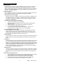
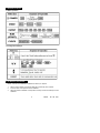
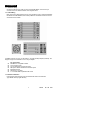
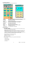
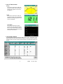
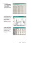
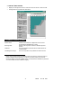
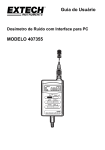
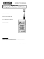
INSTRUCTION MANUAL Model 407355 Datalogging Noise Dosimeter with PC Interface • 5 Event Data Storage • Personal noise accumulation tests • 70 to 140dB sound level measurements • RS-232 PC Interface 1. INTRODUCTION Congratulations on your purchase of Extech’s Dosimeter. This professional meter, with proper care, will provide years of safe reliable service. 1 407355 Ver. 1.02 9/99 2. SPECIFICATIONS Applicable Standards Microphone Display DOSE Range Criterion Level Threshold Level Exchange Rate High Level Detector Peak Flag Sound level range Accuracy Frequency Weighting Frequency Response Response time Operating Temp/Humidity Storage Temp/Humidity Power supply Dimensions Weight Accessories ANSI S1.25-1991 A-weighting; ISO-1999, BS 64021983 1/2-inch electret condenser microphone w/ 31” cable Multifunction 4-digit LCD Display .01 to 9999% DOSE Selectable 80, 84, 85, 90dB Selectable 70 to 90dB (1dB Steps ) Selectable 3, 4, 5, 6dB 115dBA 140dBA 70 to 140 dBA ±1.5dB ‘A’ type 20Hz to 10KHz Selectable (F) FAST / (S) SLOW o o 32 to 122 F (0 to 50 C) ,10-90%RH o o 14 to 140 F (-10 to 60 C) ,10-75%RH 4 size ‘AAA’ alkaline batteries; 32 hour battery life 4.2 × 2.4 × 1.3” (106 × 60 × 34mm) 11.2 oz. (350g) TM Carrying case, screwdriver, batteries, Windows software, RS-232 cable, 9 pin to 25 pin gender adapter CE Certification: CE-mark indicates compliance EMC Directive EMC Emission EMC Immunity EN50081-1 (1992): Generic emission standard. Part 1 : Residential, commercial and light industry EN50081-2 (1993): Generic emission standard. Part 2: Industrial environment CISPR22 (1993): Radio disturbance characteristics of information technology equipment. Class B Limits FCC Rules, Part 15: Complies with the Limits for a Class B digital device EN50082-1 (1992): Generic immunity standard. Part 1: Residential, commercial and light industry RF immunity implies that sound level indications of 70dB or greater will be affected by no more than ±1.5dB EN 50082-2 (1995): Generic immunity standard. Part 2: Industrial environment RF immunity implies that sound level indications of 70dB or greater will be affected by no more than ±1.5dB 2 407355 Ver. 1.02 9/99 3. METER DESCRIPTION 1. Microphone 2. LCD Display 3. Power ON/OFF key 4. RUN / Left Arrow key 5. SPL, DOSE, TIME Mode and Left Arrow key 6. Event / Up Arrow key 7. Real time clock / Right Arrow key 8. Reset key (clears Event data) 9. Calibration screw 10. Battery Cover 11. Belt clip 12. PC interface connector 4. DISPLAY DESCRIPTION 1. 2. %DOSE icon Peak detector (> 140dBA) icon 3. TIME display icon 4. Sound Level measurement icon 5. High level warning icon (> 115dBA) 6. Event register E1-E5 7. Battery health icon 8. Fast response time icon 9. Slow response time icon 10. Noise accumulation icon 11. Measurement pause (hold) icon 5. DOSE CONSIDERATIONS DOSE is a parameter used to quantify noise exposure over a period of time. 100% DOSE is considered to be a 90 dBA noise level over an 8 hour period (in the US, for example). This value of DOSE is known as the CRITERION. Other Criteria are used, for example 100% DOSE = 85dBA for some other countries. To see how this works, use the 90dBA example above and apply it the following. 1. A person experiencing a noise level of 90dBA would receive a 50% DOSE in 4 hours. 2. If the noise level was 95dBA (5dB higher), a 100% DOSE would be accumulated in only 4 hours. This is because of what’s known as the Exchange Rate whereby a 5dB increase (selectable) in noise level corresponds to a doubling of noise energy. 3. The Criterion Level, Exchange Rate and Threshold level are determined by the applicable national noise standard. Always check the local regulations before using the meter. 3 407355 Ver. 1.02 9/99 6. OPERATING INSTRUCTIONS 6. 1 Meter Power Power the meter by pressing the green POWER key, all of the display annunciators will appear briefly and the default configuration values will appear one by one. The main display screen will then appear. If the meter does not power correctly, check the batteries. To remove meter power, press and hold the green POWER key until the meter counts down (3, 2, 1, 0) and powers OFF. 6.2 Operation Modes Press the MODE key to select or change the mode of operation (%DOSE, Sound Level in dBA, or TIME). The following is a list of Display and Measurement Modes: Instantaneous Sound Level (dBA) Measuring range is 70 to 140dBA. For Sound Level measurements < 68dBA the LCD will display dashed lines. For readings > 115dBA, the High Level Alert icon appears. For readings > 140dBA, the Peak Detector icon appears (see the DISPLAY section above for icon identification). Noise Exposure period measurements (DOSE) 1. 2. 3. 4. 5. Use the Mode selection key to choose DOSE. Select an unused Event Register (E1 through E5). Refer to the Event Select explanation below. Press the RUN key to begin measuring accumulated noise exposure. The LCD will show % DOSE and the clock icons. To stop measurement, press and hold the RUN key for 3 seconds. The measurement session will end and the clock icon will disappear. Elapsed DOSE Measurements (TIME) To view Elapsed Time (since measurement began), press the MODE key until the TIME icon appears on the LCD. The LCD will display hours and minutes. You can switch between TIME and DOSE displays at anytime. NOTE: When the RUN key is pressed, the previous DOSE measurement will be cleared. Pause / Continue When the RUN key is pressed, noise exposure measurements are held and the Pause indicator appears. To resume (continue) basic meter operation, press the RUN key again. Event Select Press the EVENT key to enter the EVENT mode. Each time the EVENT key is pressed the LCD increments the Event register (E1 through E5). Each register is a memory location. You can store and write over the data in any of these locations. Each register location (E1, for example) is displayed on the LCD along with the stored data. If data is present in a register location, the location ID blinks. To erase data in a memory location, press the RESET key. Press the EVENT key to scroll through the registers (the last scroll turns off the EVENT function). Real Time Clock Press the CLOCK key to display the current Day and Time accompanied by the TIME icon blinking. Date and time data is stored with each memory reading. The instrument has a battery back-up utility so that data and time information is not lost upon Power down. 6.3 Running a Noise Exposure Test 1. Fit the meter to the user via the microphone clip and the belt clip. The microphone must be clipped as close to the user’s ear as possible for best results. 2. Press the RUN key, the meter will begin to accumulate noise exposure. 3. Run the tests over a period of a few days to obtain better averaged data. 4. At the end of the test, press and hold the RUN key for 3 seconds. 4 407355 Ver. 1.02 9/99 7. REFERENCE TABLES 7.1 Basic Operation 7.2 Configuration Settings 8. CALIBRATION PROCEDURE NOTE: A Sound Level Calibrator, available from Extech, is required. 1. 2. 3. Set the meter to display sound level (dBA) with a SLOW (S) Time constant. Insert the meter’s microphone into the Calibrator. Adjust the meter’s calibration screw (bottom of meter) to match the dB output of the Calibrator. 5 407355 Ver. 1.02 9/99 9. METER CONFIGURATION SETTINGS To change the meter’s default settings, first remove meter power. Press and hold the RESET key while applying meter power. The current month (3-letter format) will briefly appear (let go of the RESET key now) followed by Lc (Criterion Level) with a blinking value. Change the value using the Up/Down arrow keys (MODE/EVENT keys). Scroll through the parameters using the right arrow (CLOCK) key. Change their settings using the Up/Down arrow keys. The following settings can be changed. Press the RESET key to leave the configuration mode. Changes made are protected by non-volatile battery backup. 10. MAINTENANCE 10.1 Battery Replacement The battery meter on the left side of the LCD informs the user as to the health of the battery. Replace the batteries when the battery icon appears drained. Remove the flathead screw on the rear of the meter. Remove the belt clip to expose the 4 x ‘AAA’ batteries. Replace the batteries observing proper polarity. Replace the clip and the screw. 10.2 Storage Keep the Instrument in a dry location. For long term storage, remove the batteries. 10.3 Cleaning the meter Wipe the meter case with a damp cloth. Do not use abrasive or solvents. Do not allow moisture to enter the microphone, connectors, or housing. 10.4 Meter handling and other considerations Do not attempt to remove the microphone grid. Do not attempt to open the instrument. Never mix different makes/types of batteries. Don’t mix charged/discharged batteries. 6 407355 Ver. 1.02 9/99 11. PC INTERFACE 11.1 Hardware Setup Connect the RS-232 5-pin male connector to the DOSE Meter. Connect the 9-pin connector to the PC COM Port. Refer to the diagram below. 11.2 Cable/Wiring Refer to the wiring diagram below for any wiring questions. Keep in mind that Hardware Handshake must be disabled; RTS must be pulled low via software in order to achieve successful communication. If COM2 is used on your PC, you will need a 9- to 25-pin (female) adapter (included). The diagram at right is a schematic for a 9- to 25-pin adapter. PC requirements 486 IBM PC / compatible or better One 3.5” floppy drive Two (2) Serial ports (mouse and meter) 4M bytes or better of RAM and Hard Drive space EGA/VGA monitor Windows 3.1x or better 3- or 2-button IBM compatible serial mouse 11.3 Software Installation Insert program disk into floppy drive and transfer disk data to the hard drive. Type SETUP at the program directory 7 407355 Ver. 1.02 9/99 11.4 DOSE Meter Windows Refer to diagrams below for Main Menu Control Panel Sample: Last Time: File Name: Response: Value: Exchange rate: Minimum: Maximum: Reset: Criterion level: Range: Threshold level: The value under SAMPLE is the rate at which readings are recorded. LAST TIME is the time of day of the last recorded reading File where data are stored (F) Fast and (S) Slow modes The text under VALUE is the Dosimeter measurement. There are four exchange rates (3, 4, 5, and 6dB). The minimum value recorded. The maximum value recorded. Clear minimum and maximum values There are four criterion levels (80, 84, 85, 90dB). 70-140dBA (Sound Level) 70 to 90dB selectable in 1dB steps. 11.5 Menu functions 1 ‘FILE’ MENU HEADING Open: Open an existing file from your directory or start a new file. After opening a file, the file name appears under "File name". Start Recording: Stores the data received from Dosimeter to the opened file. The recording sample rate appears under "Sample". For example, if the value under "Sample" is 2 Sec, then the program will save one record to the opened file every 2 seconds. The “Recording” symbol will be appear on the PC monitor. Stop recording: Click here to Stop recording. View file: Load data from file to table. Exit: Close the program With the Dosimeter connected to a PC, log the SPL data as follows: c File / “open” d “Start Recording” e “Stop Recording” f “View file” 8 407355 Ver. 1.02 9/99 2. ‘DISPLAY’ MENU HEADING Analog If this option is selected or CTRL+A is pressed, a window, which emulates an analog meter, appears on the screen. See diagram. Digital If this option is selected or CTRL+D is pressed, a window, which emulates the Dosimeter LCD display, appears on the screen. See diagram. Sound Wave If this option is selected, a window appears which will rapidly plot dB over time. The horizontal scale is 4 seconds and the display will plot at approximately 200mS per measurement. 3. ‘OPTION’ MENU HEADING Occupational Noise Exposure Standards differ for each country. This window, shown below, permits the user to see the required settings to meet the dosimeter standards in many countries. The user can also set the standard on the Dosimeter directly from the PC. 9 407355 Ver. 1.02 9/99 11.6 GRAPH MENU 1. ‘LIST’ MENU HEADING Lists the date, time, Value (SPL or %DOSE), TWA, criterion level (CL), Response, and exchange rate (ER) 2. ‘GRAPH’ MENU HEADING When selected, a window, which emulates a strip chart recorder appears. This feature can only be used with “real time” data acquisition. Data previously stored in a file can not be graphed using this program. 3. ‘EVENT’ MENU HEADING Download and save the five independent events stored in the E1-E5 memory locations. Use the “Bank” menu to download the events. Use the “File” menus to save or recall a file. 10 407355 Ver. 1.02 9/99 4. ‘AVERAGE’ MENU HEADING — Displays the average Sound Level. Time interval can be set from 2 to 60 seconds. — Average data can be saved to file. See below: 12. DOSIMETRY GLOSSARY OF TERMS Criterion Level Exchange Rate Threshold Time Weighted Average Constant sound level that, if applied for 8 hours, would accumulate the allowable dose of 100% Number of dB required to double the allowable exposure duration. The sound pressure level below which measurements are considered 0dB The 8 hour equivalent of any dB level recorded over time. 13. CALIBRATION / REPAIR SERVICES Extech offers complete repair and calibration services for all of the products we sell. For periodic calibration, NIST certification or repair of any Extech product, call customer service for details on services available. Extech recommends that calibration be performed on an annual basis to insure calibration integrity. 11 407355 Ver. 1.02 9/99 14. WARRANTY EXTECH INSTRUMENTS CORPORATION warrants this instrument to be free of defects in parts and workmanship for one year from date of shipment (a six month limited warranty applies on sensors and cables). If it should become necessary to return the instrument for service during or beyond the warranty period, contact the Customer Service Department at (781) 890-7440 for authorization. A Return Authorization (RA) number must be issued before any product is returned to Extech. The sender is responsible for shipping charges, freight, insurance and proper packaging to prevent damage in transit. This warranty does not apply to defects resulting from action of the user such as misuse, improper wiring, operation outside of specification, improper maintenance or repair, or unauthorized modification. Extech specifically disclaims any implied warranties or merchantability or fitness for a specific purpose and will not be liable for any direct, indirect, incidental or consequential damages. Extech's total liability is limited to repair or replacement of the product. The warranty set forth above is inclusive and no other warranty, whether written or oral, is expressed or implied. 12 407355 Ver. 1.02 9/99