1
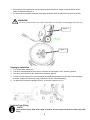
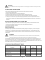
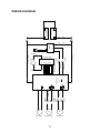
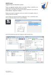
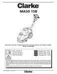
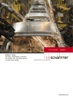
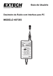
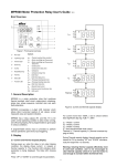
OWNER’S MANUAL IMPORTANT: READ OWNER’S MANUAL CAREFULLY MODEL # PANTHER 15B MICRO SCRUBBER FOR YOUR CONVENIENCE, RECORD THE FOLLOWING IMPORTANT INFORMATION MODEL: ___________________________________ SERIAL NUMBER: ____________________________ DATE PURCHASED: ___________________________ PURCHASED FROM: __________________________ TABLE OF CONTENTS Safety Precautions 1 Machine Set Up & Installation 2-4 Machine Operation 4-5 Maintenance 5-6 Battery Charging 6 Preventative Maintenance 7 Parts Breakdown & Lists 8-10 Wiring Diagram 11 Troubleshooting 12 Warranty 13 SAFETY PRECAUTIONS This machine is intended for commercial use. It is constructed for use in an indoor environment and is not intended for any other use. Use only with recommended accessories. All operators shall read, understand and exercise the following safety precautions: 1) DO NOT OPERATE MACHINE: Unless trained and authorized. Unless you have read and understand the operators manual. In flammable or explosive areas. If not in proper operating condition. In outdoor areas. 2) BEFORE OPERATING MACHINE: Make sure all safety devices are in place and operate properly. 3) WHEN USING MACHINE: Go slow on inclines and slippery surfaces. Follow all safety guidelines. Be very careful when using the machine in reverse. Report and fix any damage to machine prior to operating it. 4) BEFORE LEAVING OR SERVICING MACHINE: Stop machine on level ground. Turn machine off. 5) WHEN SERVICING MACHINE: Read operators manual thoroughly prior to operating or servicing this machine. Use manufacturer supplied or approved replacement parts. Secure machine with wheel blocks prior to jacking the machine up. Use approved jack or hoist to safely elevate the machine. Disconnect batteries prior to working on machine. Wear gloves when handling batteries or battery cables. Avoid any contact with battery acid. Avoid moving parts. Do not wear loose fitting clothing while servicing machine. WARNING! Batteries emit hydrogen gas. Explosion or fire can result from hydrogen gas. Keep sparks and open flames away! Keep battery compartment open when charging. WARNING! Flammable materials can cause an explosion or fire. Do not use flammable materials in tanks. WARNING! Flammable materials or reactive metals can cause explosion or fire. Do not pick up. 1 MACHINE SET UP & INSTALLATION UNCRATING MACHINE Be sure and check packing carton for any damage. Immediately report any damage to carrier. Check contents of package to ensure that the following items are included: 1. Machine 2. Batteries (x2) 3. Squeegee assembly 4. Scrubber-dryer User Manual 5. Electric Battery Charger Manual(if equipped) 6. Connecting wire for battery and charger(if equipped) 7. Brush or pad driver(if equipped) BATTERY DISASSEMBLY AND INSTALLATION 1. 2. 3. 4. 5. Switch off the main switch (47). Remove the recovery tank (2) as shown in the relevant paragraph. Unscrew the bolt from batteries (16), then remove or change. Install the batteries on the machine according to the diagram below. Install the recovery tank. WARNING! Do not connect+ to +,or - to-,when disassembly or install the batteries. It is very dangerous. Figure 1 Battery charging Charge the batteries (see battery charging section). MACHINE SET UP Pre-operation Checks 1. 2. 3. 4. 5. Sweep or dust mop the surface to be cleaned. Check that squeegee is properly installed. Lower the squeegee (33) with the lift lever (26). Be sure batteries are fully charged (see Battery Charging section). Check that brush/pad is properly installed. Brush/Pad Driver Installation and Disassembly NOTE 1. 2. Only install manually. If auto-installation, it will wear brush hub. Make sure that the tanks are empty before disassembling the brush. Turn off the machine. Lay down the machine in this position as indicated in figure 2. Pull up the lift lever (26) to raise the squeegee up (33). 2 3. Mount the brush or pad driver onto the drive wheel hub and then rotate counterclockwise until it locks, as indicated in figure 3. 4. To remove the brush/pad, rotate the brush/pad clockwise until it is released from drive wheel hub. WARNING! Do not turn on the machine in the position shown below. The brush/pad could disengage and cause injury. Figure 2 Figure 3 Squeegee Installation 1. Turn off the main switch (47). 2. Pull down the squeegee lift lever (26) to put down the squeegee on the “working” position. 3. Lay down the machine in this position as indicated in figure 2. 4. Loosen the two knobs (55) on the squeegee and slide the squeegee into the slots of the squeegee brackets. Tighten the knobs securely (unscrew the knobs, if disassembling). 5. To replace the front/rear squeegee (56/57), unscrew the thumb nut (37). Solution Tank F illing NOTE The machine can be filled filling. with a pipe or bucket. Do not remove the Solution F ilter (21) while 3 1. Fill water into solution tank (3) from the inlet (20) through pipe or bucket. 2. Do not fill the solution tank completely, leave a few centimeters from the edge. 3. The water temperature must not exceed 40℃. CAUTION! Use only low-foam and non-flammable detergents, intended for automatic scrubber applications. Solution Tank D raining NOTE Solution tank should be drained and cleaned after each scrubber operation is completed. 1. Unscrew the solution tank drain cap (22) on the bottom of the solution tank. The solution/water will flow freely into a bucket or floor drain. 2. Rinse the solution tank with clean water after every use. This will help prevent chemical build up and clogging of the solution lines. 3. Screw on the solution tank drain cap (22). Recovery Tank D raining NOTE Recovery tank should be drained and cleaned after each scrubber operation is completed. 1. Turn the latch (17) off the recovery tank, take off the recovery tank from machine by grasping two grooves of tank. Open the lid (1) and overturn the recovery tank to drain the dirty water into a container, or unscrew the solution tank drain cap (22) to let water pour out to a bucket. 2. Clean and rinse the recovery tank with clean water after every use. 3. Replace the recovery tank on the machine and turn the latch (17) to lock the tank. MACHINE OPERATION 1. 2. 3. 4. 5. 6. 7. Set the handle to a comfortable height by pressing handle rotate lever (25). Lower the squeegee (33) onto the floor by pulling down the squeegee lift lever (26). Turn on the main switch (47). Turn on the brush motor switch (48) and the solution switch (50), the indicate light will be on. Turn on the vacuum motor switch (49), the indicate light will be on. If necessary, adjust the water flow by turning the solution flow control lever (31) manually. Pull one or both operating triggers (24), and then brush will start to spin, solution will begin to flow. Move the machine and start cleaning. NOTE . If the battery indicator light (51) is green, the machine can be used. If it is yellow or red, the batteries must be charged. CAUTION! Before lifting the brush, turn it off by pressing the main switch (47). CAUTION! When cleaning excessively aggressive floors this may cause the machine to not work. B rush motor and vacuum indicators on the control panel (46) will flash simultaneously. T his means the machine is being overloaded. Please turn off all the switches on the control panel (46). 4 CAUTION! Do not use the machine with discharged batteries to avoid damaging the batteries and reducing the battery life. AFTER USING THE MACHINE After scrubbing, please proceed with below actions before leaving the machine: 1. Remove the brush/pad holder. 2. Empty the tanks as shown in the previous paragraph. 3. Perform the daily maintenance procedures (see the maintenance section). 4. Store the machine in a clean and dry place, with the brush/pad holder and the squeegee. 5. If storing in an area which may reach freezing temperatures, be sure to drain all fluids from the machine prior to storage. Any damage caused by freezing temperatures will not be covered by the warranty. DO NOT USE MACHINE FOR A LONG TIME If the machine is not going to be used for more than 30 days, please proceed with below actions: 1. Perform the procedures shown above in (After Using the Machine section). 2. Disconnect the battery connector. MAINTENANCE The lifespan of the machine and its maximum operating safety are ensured by correct and regular maintenance. The following chart provides the scheduled maintenance. The intervals shown may vary according to particular working conditions, which will be defined by the person in charge of the maintenance. WARNING! Maintenance procedures must be performed with the machine switched off and the batteries/battery charger cable disconnected. C arefully read the instruction in the Safety precaution section. All scheduled or extraordinary maintenance procedures must be performed by qualified personnel, or by an authorized Service Center. This manual describes the easiest and most common maintenance procedures. For other maintenance procedures shown in the Scheduled Maintenance Table, refer to the Service Manual that can be consulted at any Service Center. SCHEDULED MAINTENANCE TABLE Daily, (after using Procedure the machine) Battery charging Squeegee cleaning Brush cleaning Tank and vacuum grid with float cleaning, the cover gasket check Squeegee blade check and replacement Solution filter cleaning 5 Weekly Every Six Months Y early Out-water pipe filter cleaning Screw and nut tightening check (1) rotary parts lubricated (1) (2) Brush/Pad holder motor carbon brush check or replacement (2) Vacuum system motor carbon brush check or replacement ( 1) After the first 8 working hours. (2) This maintenance procedure must be performed by an authorized Service Center. BATTERY CHARGING NOTE Charge the batteries when the yellow or red indicator (51),or at the end of every working cycle. CAUTION! Keeping the batteries charged makes battery life last longer. CAUTION! ! If the machine is not equipped with on-board battery charger, choose an external battery charger suitable for the type of batteries installed. WARNING! Please use appropriate charger to charge the battery. WARNING! Pay careful attention when charging WET batteries as there may be battery fluid leaks. The battery fluid is corrosive. If it comes in contact with skin or eyes, rinse thoroughly with water and consult a physician. 1. 2. 3. 4. Place charger and machine in a well ventilated area. Turn machine off (47). Take away the recovery tank (2). Exposing battery compartment. Plug the charging cable to the grounded wall outlet (100v~240v). Connect the charging cable to the machine socket. 5. The charging indicator light (30) turns on when it' s charging, green light means battery charging is completed. 6. Upon the completion of charging, first unplug the charging cable from the wall outlet and then disconnect from machine. 7. Replace the recovery tank . NOTE For further information about the operation of the battery charger (29), see the relevant section. 6 SQUEEGEE CLEANING NOTE The squeegee must be clean and its blades must be in good condition in order to getting a good drying performance. CAUTION ! It is advisable to wear protective gloves when cleaning the squeegee because there may be sharp debris. SQUEEGEE BLADE CHECK AND REPLACEMENT 1. 2. 3. 4. 5. Take off the squeegee as shown in the previous paragraph. Check to see if the edge of the front/rear blades are cracked or split, if necessary replace them with new. Unscrew the thumb nut (37) to remove the blades. Check the front/rear blades for integrity, cut and tears. Replace if necessary. Install the squeegee in the reverse order of removal. BRUSH/PAD DRIVER CLEANING CAUTION! It is advisable to wear protective gloves when cleaning the brush/pad because there may be sharp debris. 1. 2. 3. 4. Remove the brush/pad as shown in Machine set up section. Clean and wash the brush/pad with water and detergent. Check the brush bristles for integrity and wearing status; if necessary, replace the brush. Check the pad for wearing status; if necessary, replace the pad driver. TANK/VACUUM GRID WITH FLOAT CLEANING AND COVER GASKET CAUTION! It is advisable to wear protective gloves when cleaning the tank and vacuum/suction assembly because there may be sharp debris. 1. 2. 3. 4. 5. Move the machine to the appointed disposal area. Turn off the main switch (47). Take off the recovery tank (2), clean and rinse both solution/recovery tank, and drain out. Take off all vacuum kits, gasket, filter, clean and re-install. Check the recovery tank lids gasket ring and the vacuum rubber connector (18) between two tanks are integrity or not. NOTE The gasket ring of recovery tank and the rubber connector between two tanks create vacuum in the tank. If necessary, replace them. . 7 PARTS LIST 1. 2. 3. 4. Recovery tank lid Recovery tank Solution tank Brush cover 46.Control panel 5. 6. 7. 8. 9. 10. 11. 12. 13. 14. 15. 16. 17. 18. 19. 20. 21. 22. 23. 24. 25. 26. 27. 28. 29. 30. 31. 32. 33. Protective rollers Brush Front handle shell Control panel Rear handle shell Handle rubber Handle iron pipe Squeegee vacuum assembly Squeegee suction assembly Left positioning Right positioning Batteries Latch Rubber sealing Limit hose joint Inlet Solution filter Solution tank drain Wheels on fixed axle Handle left and right Handle rotate lever Squeegee lift lever Squeegee string Box circuit Battery Charger Battery charge indicator Solution flow control lever Electromagnetic valve data Squeegee 50.Suction Electromagnetic valve data switch 51.Electric quantity indicator 52.Brush motor indicator 34. 35. 36. 37. 38. 39. 40. 41. 42. 43. 44. 45. Squeegee wheels Squeegee hose Axle Thumb nut Vacuum system motor Brush motor Drive belt Belt Squeegee rotation plate Squeegee lift plate Squeegee fixing plate Motor fixing plate 47.Main switch 48.Brush motor switch 49.Vacuum motor switch 53.Vacuum motor indicator 54.Suction Electromagnetic valve data indicator 55. Knob 56. 57. 58. 59. 8 Front squeegee Rear squeegee Squeegee adjustment piece Screw nut PARTS BREAKDOWN 7 12 13 1 21 20 19 9 10 22 11 2 3 8 18 4 15 38 39 14 17 16 45 23 40 5 6 22 25 41 42 32 24 59 33 34 26 27 58 31 28 29 30 36 33 9 35 37 57 43 44 56 Control Panel 46. 47. 48. 49. 50. Control panel Main switch Brush motor switch Vacuum motor switch Suction Electromagnetic valve data switch 51. 52. 53. 54. Electric quantity indicator Brush motor indicator Vacuum motor indicator Suction Electromagnetic valve data indicator TECHINICAL DATA Machine length x width x height 770x500x550MM Solution tank capacity 15L Recovery tank capacity 15L Wheel diameter 254MM Brush motor data 24V 250W Vacuum motor data 24V 300W Electromagnetic valve data 24V Maximum gradient 2% Sound level 68dBA Batteries data (2×12V)24V 33Ah/20h Power cable length / Batteries spec 196 x 130 x 175mm Working capacity, up to 800mm Cleaning productivity 750m /hour 2 Squeegee width 490mm Brush diameter 380mm Brush rpm 150rpm Input 100-240 Vac,50-60HZ Output 24Vdc,5A Charger Machine weight 60kg Machine weight(with charger and package) 65kg Carton spec 780x415x590MM 10 WIRING DIAGRAM 12AWG BLACK - 12V STORAGE BATTERY + 16AWG RED + CHARGER 18AWG BLACK 18AWG RED COMMUNICATION LINE J8.1 J8.3 J9.1 J9.2 J9.3 J9.4 J9.5 J9.6 J9.7 VCC CB PTC CONTROL BOARD GND J3 PRUSH PTC J2 J7.2 J5 J4 VACUUM PTC WV PTC J7.1 1# 14AWG BLACK 1# 14AWG RED 2# 14AWG BLACK 2# 14AWG RED LINKE C2.1 LINKE C2.2 LINKE C3.1 LINKE C3.2 M M WV BRUSH MOTOR 12AWG RED LINKE C1.1 J11.2 J10.1 J10.2 J10.3 J10.4 J10.5 J10.6 J10.7 LINKE C1.2 J11.1 SAFETY SWITCH 20AWG WHITE RED - KEY-PRESS BOARD 12AWG BLACK 11 VACUUM MOTOR WATER VALVE 12V STORAGE BATTERY 16AWG BLACK 12AWG 12AWG BLACK 20AWG WHITE TROUBLESHOOTING Trouble Possible Cause Remedy The battery connector is disconnected Connect The machine does not work, indicator The batteries are completely discharged Charge the batteries light (51) does not turn on The power line disconnected from the power Connect The machine does not work, indicator The batteries are discharged Charge the batteries The PCB or key board is faulty Change the PCB or key light (51) turns red Brush motor does not work, brush board indicator light (52) does not turn on The deck motor is overloaded Use less aggressive brushes suitable for the floor to be cleaned Brush motor does not work, brush indicator lights (52) flash There are foreign materials (tangled Clean the brush hub threads,etc) preventing the brush from rotating Vacuum system motor does not work, The PCB or key board is faulty Change the PCB or key board vacuum motor indicator light (53) does not turn on Vacuum system motor does not work, The vacuum system motor is overloaded Check the vacuum system motor brush indicator lights (53) flash The recovery tank is full The hose is disconnected from the Empty the recovery tank Connect squeegee The suction power is insufficient Vacuum assembly is clogged Clean or check The squeegee is dirty, or the squeegee Clean and check the blades are worn or damaged squeegee The recovery tank is not locked Lock the latch (17) The tank cover is not properly closed, or the Close the cover properly gasket is damaged or replace the gasket Squeegee ad justment piece(58 )not set at an Adjust the screw nut(59 )to The solution flow is insufficient The squeegee leaves marks on the floor appropriate position the appropriate position The solution is empty Fill the tank Solution flow control valve (31) is blocked up Clean the valve The solution is dirty Empty the solution,clean the tank and refill with clean solution. There is debris under the squeegee blades Remove the debris The squeegee blades are worn, chipped or Replace the blades torn 12 WARRANTY POLICY The warranty terms outlined below are in lieu of any other warranties, either stated or implied, including any implied warranty of merchantability, fitness for a particular purpose or otherwise. Under no circumstances will seller be liable for any loss, damage, expense or consequential damages arising in connection with the use or inability to use this product. This warranty does not apply to damage or defect caused by accident, misuse, negligence, abuse, fire or to any Triple S product which has been serviced by anyone other than a Triple S authorized service representative. Housings or parts that have become damaged as a result of improper use of the machine are excluded from this warranty. Refer to owner’s manual for proper machine use and maintenance. Parts that are expected to wear from normal use and, therefore are not covered under the parts warranty include, but are not limited to: batteries (pro-rated for one year); bearings; belts; brushes; filters; squeegees; switches; and tires. This warranty commences on the date of purchase of the product by the original end user from an authorized Triple S distributor, subject to proof of purchase. If proof of purchase date is unavailable, the warranty begins 90 days after the sale of the product to an authorized Triple S distributor. Subject to the conditions outlined above, the manufacturer warrants the rotationally-molded polyethylene housings and parts on its machines to be free from defects in materials and workmanship, under normal use and service for twelve (12) years to the original purchaser. Under this warranty, the manufacturer guarantees the performance of non-polyethylene parts and components on Triple S machines to be free from defects for up to five (5) years to the original end user. Parts replaced under this warranty are guaranteed for the remainder of the original warranty period. Labor charges are covered for five (5) full years from the date of purchase for Triple S products, provided an authorized Triple S service provider is used for repair. No travel coverage is extended for cord electric machines. Product Exceptions & Exclusions: Battery chargers and all accessories are warranted for one year. Triple S reserves the right to change the warranty policy without notice.