1
ADJUSTING FENCE "
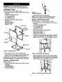
Refer to F'_ure 18 and 19.
Jointer/planer has fence bevel stops at 90 ° (from bed)
and 45 °. These stops are set at the factory, but may
have fallen out of alignment while in transit. To check for
squareness:
• Turn the stop screws so they touch the fence.
T'_hten jam nuts.
• Loosen the tilt knob.
Place an accurate square on outfeed table and
check fence while locked at 90 ° position.
• Make sure that the bottom of the outfeed side of the
fence rests firmly against the outfeed table and
against the head of the two stop screws.
•
Move the fence to any angle and then return it to the
index and check for accuracy.
•
Readjust the 90 ° and 45 ° stops if necessary until the
stop maintains an accurate and repeatable fence
setting.
•
ADJUSTING
KNIFE HEIGHT
Refer to Figures 20, 21 and 22, pages 10 and 11.
WARNING: Make sure the switch is in the "OFF" position and the tool is disconnected from the power source
before making any adjustment.
CAUTION: The cutterhead knives are extremely sharp.
Do not let your fingers contact the cutting edge at any
time.
To produce even surface on a workpiece, the knife edge
must be at the same distance from the axis of the cutterhead. The knife height comes adjusted from the factory and should require no adjustment.A knife gauge has
been provided to make knife height adjustment easy.
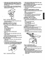
The knife height setting gauge must be assembled. To
assemble:
•
Identify and locate the following parts from hardware
bag.
Knife Gauge (2)
Knife Gauge Rod (1)
3 CMI-10 Retaining Ring
•
Attach the two inside retaining rings to the shaft.
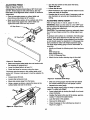
Figure 18 - Fence Stop
• Make sure that the infeed table does not interfere with
the accuracy of measurement.
•
Lower the infeed tableto at least '/;6".
•
Check the fence for accuracy using the stops.
The fence must be square to the ouffeed table at 90 °
and at 45 °. If fence is not square it must be adjusted. To
adjust:
Loosen fence tilt knob.
•
Loosen _top screw jam nuts.
•
Move stop screws away from the fence.
•
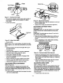
Using a square as shown, square the fence to the
outfeed table and lock the tilt knob.
Rgure 20 - Assemble Knife Gauge
• Slide one of'the gauges onto the shaft and attach
the outside retaining ring to hold gauge in place.
• Repeat for the other gauge.
The knife height setting gauge is ready to check knife
height. To ch.eckknife height:
_
_
-I=hJWrete - Adjust Fence
10
•
Lower infeed table by turning the depth of cut handwheel clockwise.
•
Position the fence to the rear of the jointer, approximately '/," beyond the cutter knives.
•
Lock the fence in this position.
•
Remove the knife guard.
•
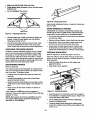
Place the gauge on the cutterhead as shown in
Figure 21, page 11.