1
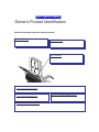
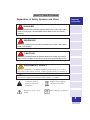
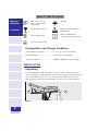
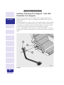
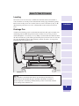
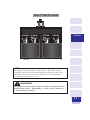
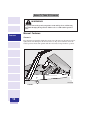
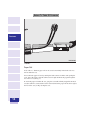
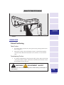
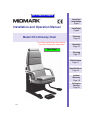
Go To Table Of Contents
Important
Information
Page 4
Installation and Operation Manual
Model 413 Lithotomy Chair
To purchase a printed copy of this manual,
click on the "Place Order" button below.
Installation
Page 6
Features
Page 10
Operation
Page 15
Place Order
Cleaning
Page 17
Maintenance
Page 17
Specifications
Page 18
Limited
Warranty
Page 19
Calling for
Service
Page 20
Style C
Go To Table Of Contents
Owner's Product Identification
(Have this information ready when calling for service)
Date of Purchase
Model Number
Serial Number
Name of Owner/Facility/Department
Name of Authorized Midmark Dealer
Address of Authorized Midmark Dealer
Telephone # of Authorized Midmark Dealer
Contents
IMPORTANT INFORMATION ............................................................................................. 4
Scope and Purpose of This Manual .............................................................................. 4
Intended Use of Product ............................................................................................... 4
Authorized CE Representative ...................................................................................... 4
Safety Instructions ....................................................................................................... 4
Explanation of Safety Symbols and Notes .................................................................... 5
Transportation and Storage Conditions .......................................................................... 6
INSTALLATION ................................................................................................................. 6
Unpacking .................................................................................................................... 6
Installing Foot Supports - Units With Permanently Mounted Foot Supports .................. 7
Installing Foot Supports - Units With Detachable Foot Supports ................................... 8
Leveling ........................................................................................................................ 9
Drainage Pan ................................................................................................................ 9
Electrical .................................................................................................................... 10
FEATURES ...................................................................................................................... 10
Power Features ........................................................................................................... 10
Footswitch ...................................................................................................... 10
Manual Features ......................................................................................................... 12
Armrests ......................................................................................................... 12
Footrest .......................................................................................................... 13
Paper Roll ....................................................................................................... 14
OPERATION .................................................................................................................... 15
Patient Positioning ...................................................................................................... 15
Table Position .................................................................................................. 15
Trendelenburg Position .................................................................................... 15
Lithotomy Position .......................................................................................... 16
CLEANING ...................................................................................................................... 17
Upholstery .................................................................................................................. 17
Painted Metal Surfaces ............................................................................................... 17
Moving Parts .............................................................................................................. 17
POWER SYSTEM MAINTENANCE ................................................................................. 17
SPECIFICATIONS ........................................................................................................... 18
LIMITED WARRANTY ...................................................................................................... 19
CALLING FOR SERVICE ................................................................................................ 20
Return To Table Of Contents
Important
Information
IMPORTANT INFORMATION
Scope and Purpose of This Manual
This manual covers complete instructions for the installation, operation, and normal
care of the 413 Lithotomy Chair. It is intended that this manual be used by any medical
personnel responsible for operating the chair during a medical procedure/exam, or
performing operator level maintenance. No repair information is included in this
manual as no repairs are authorized at the operator level.
Intended Use of Product
This product is intended to be used as either a chair or table to provide positioning and
support of patients during examinations and procedures conducted by qualified
medical professionals.
Authorized CE Representative
Countries in the EEC should direct all questions, incidents, and complaints to
Midmark's authorized CE representative listed below:
Promotal
22, Rue De St. Denis
53500 Ernee,
France
Phone: 33-2-430-517-76
Fax: 33-2-430-569-10
Safety Instructions
The primary concern of Midmark is that this equipment is operated and maintained
with the safety of the patient and staff in mind. To assure safer and more reliable
operation:
• Read and understand this manual before attempting to install or operate the chair.
• Assure that appropriate personnel are informed of the contents of this manual;
(this is the responsiblity of the purchaser).
• Assure that this manual is located near the chair, or if possible, permanately affixed to
the chair.
4
Return To Table Of Contents
Explanation of Safety Symbols and Notes
Important
Information
DANGER
Indicates an imminently hazardous situation which, if not avoided, will result in
death or serious injury. The DANGER symbol is limited to the most extreme
situations.
WARNING
Indicates a potentially hazardous situation which, if not avoided, could result in
death or serious injury.
CAUTION
Indicates a potentially hazardous situation which, if not avoided, may result in
minor or moderate injury. It may also be used to alert against unsafe practices.
EQUIPMENT ALERT
Indicates an imminently or potentially hazardous situation which, if not avoided,
will or may result in serious, moderate, or minor equipment damage or malfunction.
NOTE
Note is used to amplify an operating procedure, practice, or condition.
Consult the operator's
manual for important
information
Dangerous voltage / shock
hazard
Indicates proper shipping
orientation for product.
Fuse rating/type specification
5
Return To Table Of Contents
Important
Information
Installation
Duty cycle: motor run
time - 15 seconds ON, 5
minutes OFF
Keep dry
Fragile. Handle with care.
Maximum stacking height of
palleted units
Type B, Applied Part.
Indicates minimum and
maximum storage temperatures
Protective earth ground
Transportation and Storage Conditions
• Ambient Temperature Range:....................+5° C to +38° C (+41° F to +100° F)
•Relative Humidity:.......................................10% to 90% (non-condensing)
• Atmospheric Pressure:..................................500hPa to 1060hPa (0.49atm to 1.05atm)
INSTALLATION
Unpacking
To avoid damaging the chair’s upholstery, do not use a knife or other sharp object to
open the packaging. Unbolt the chair from the wooden shipping skid by removing four
bolts on the underside of the base, one at each corner. After unbolting, remove the
chair's upholstery, release from the skid, lifting only at points “A” and “B” in Fig. 1.
A
FIGURE 1
6
B
Return To Table Of Contents
Installing Foot Supports - Units With Permanently
Mounted Foot Supports
To allow passage through 30" doorways, Model 413's are shipped without the foot
supports installed. The foot supports are shipped in the individual box found on the
shipping skid.
Installation
Remove the foot supports from the protective package. Open the bag containing two 3/8
- 16 x 11/14" and two 3/8 - 16 x 4" socket head cap screws. There is a 5/16" AlIen wrench
supplied for screw installation.
Place the foot support in position on the chair as shown in Fig. 2. Make sure the
counterbored holes at the end of the foot support tube faces outward from the chair. Place
a 5/16 -18 x 4" screw at A, Fig. 2, and lightly tighten. Place a 5/16 -18 x 11/14" screw at
B, Fig. 2, and lightly tighten. Tighten both screws securely.
Repeat above procedure for opposite foot support. Run chair from lithotomy to chair
position. Check for linkage interference or pinched wiring.
B
A
D
C
FIGURE 2
7
Return To Table Of Contents
Installing / Removing Foot Supports - Units With
Detachable Foot Supports
Installation
To allow passage through 30" doorways, Model 413's are shipped without the foot
supports installed. The foot supports are shipped in the individual box found on the
shipping skid.
To install a detachable foot support (A, Fig. 3), pull outward slightly on release knob (B,
Fig. 3) and slide foot support into bracket (C, Fig. 3). Release the release knob (B, Fig.
3), allowing it to secure the foot support to the bracket. Pull on foot support to ensure
foot rest is securely latched. Repeat procedure for remaining foot support.
To remove a detachable foot support (A, Fig. 3), pull release knob (B, Fig. 3) outward
and then pull foot support off of bracket (C, Fig. 3). Repeat procedure for remaining foot
support.
B
C
A
MA317800
FIGURE 3
8
Return To Table Of Contents
Leveling
On level floors it is not necessary to stabilize the unit. If the chair seems unstable or
rocks, install the two leveling screws included in the arm/leg support hardware package.
Holes for the leveling screw are located at both rear corners of the chair (C, Fig. 2). By
adjusting these pads in and out, a level, solid installation can be achieved on uneven
floors.
Installation
Drainage Pan
A stainless steel drainage pan is located under the chair back. This pan is mounted on an
articulating platform which keeps it horizontal at all times. Access to the pan can be
attained through the cover (D, Fig. 2) or by sliding it out from under the chair back when
the chair is in lithotomy position. The pan is held in place by friction locks. To access the
pan, grasp the handle (A, Fig. 4) and pull firmly outward. To return to closed position
push the handle inward until it locks.
A
NOTICE
FULLY RETRACTED TO ENABLE OPERATION OF FOOT FUNCTION
MA299100
FIGURE 4
NOTE
The pan holder is electrically interlocked to prevent damage should the seat
inadvertently be moved while the pan is extended. Should the seat function
become inoperative, check the possibility that the pan has not been fully returned
to its locked position under the seat.
9
Return To Table Of Contents
Electrical
Installation
The electrical rating for this chair is 230 VAC, 50/60 Hertz, 1.5 Ampere. The grounding
plug on the chair's power cord must be inserted into a matching grounded, 230 Volt
receptacle.
WARNING
Features
If the chair malfunctions, immediately remove your foot from the footswitch,
unplug cord from the wall receptacle and assist the patient from the chair.
WARNING
EQUIPMENT ALERT
Use 230 Volt, 50/60 Hertz alternating current only. Failure to do so could result in
personal injury or equipment damage.
WARNING
EQUIPMENT ALERT
Do not use this chair in an explosive or oxygen-enriched atmosphere. Using the
chair in these situations could cause personal injury or equipment damage.
FEATURES
Power Features
For optimal performance, allow chair to reach room temperature before operating.
Footswitch
Place your foot into one of the two footswitch sections and rock your foot to activate
movement of the chair.
WARNING
EQUIPMENT ALERT
Keep all foreign objects away from the footswitch so that the pedals are not
accidentally activated. Failure to do so could result in personal injury or damage
to the chair.
10
Return To Table Of Contents
ACQUIRE
ACQUIRE
FIGURE 5
RETURN
RETURN
Features
MA299000
NOTE
This equipment is not designed for continual operation. If the unit is operated
continually, a thermal overload switch will shut off the chair motor. If this occurs,
immediately remove your foot from the footswitch. The overload switch will
automatically reset after the motor cools.
WARNING
The patient's feet must be in the foot supports at all times except when the chair is
motionless in the "Chair," "Trendelenburg," or "Table" positions. Failure to do
so could result in personal injury.
11
Return To Table Of Contents
WARNING
Keep your arms and legs and your patient's arms and legs clear of all moving
parts when changing chair positions. Failure to do so could result in personal
injury.
Manual Features
Features
Armrests
Pivot the armrests upward by lifting the arm. To lower the arm past the neutral position,
lightly lift the arm and depress the release button (A, Fig. 6). To return the arm to the
neutral position, lift the arm upward until the release button snaps back into position.
A
FIGURE 6
12
MA299500
Return To Table Of Contents
Footrest
The padded footrest may be pulled out and lifted up to extend the top to 72 3/4" in the
table and trendelenburg positions.
To extend the footrest, grasp the wire bail (A, Fig. 7) and pull the bail outward. With the
bail depressed, pull the footrest out of the seat section.
Features
A
MA299400
FIGURE 7
To bring the footrest level with the seat section, grasp the upholstered front of the footrest
and lift it up as shown in Fig. 8. Pull the footrest forward until it falls into a locked
position.
To return the footrest, grasp the upholstered front, lift upward, push the footrest back,
grasp and depress the bail and push the footrest back into the seat section until it locks
into position.
EQUIPMENT ALERT
Always return the footrest to its locked storage position when not in use. Failure to do
so could result in damage to the chair.
13
Return To Table Of Contents
Features
MA299300
FIGURE 8
Paper Roll
A 16" wide x 3" diameter paper roll can be stored conveniently in the back section as
well as under the seat.
Access the back paper roll area by turning the latch counter clockwise and opening the
cover. Place the paper roll in the stainless steel trough and insert the paper through the
slot in the cover (see Fig. 9).
To reach the paper roll under the seat, grasp the seat cushion firmly and pull from metal
seat (the cushion is secured with a Velcro fastener). Insert the paper roll into the trough at
the rear of the seat (see Fig. 6). Replace seat.
14
Return To Table Of Contents
A
B
Operation
MA299900
FIGURE 9
OPERATION
Patient Positioning
Table Position
1.
To attain the table position from a chair position, have patients put their feet in
the foot supports.
2.
Depress the left side of the pedal marked “Acquire” and hold down until the
seat is horizontal. If desired, extend the footrest, and raise or lower the chair
arms.
Trendelenburg Position
1.
To attain the trendelenburg position from the table position, depress the left side
of the pedal marked “Acquire” and hold down until the desired amount of tilt or
the maximum 10° tilt is achieved.
WARNING
EQUIPMENT ALERT
Failure to retract the footrest and lock position could result in personal injury or
chair damage.
15
Return To Table Of Contents
EQUIPMENT ALERT
Do not hold the control pedal down after the chair has reached the maximum tilt.
Operation of the chair for an extended period of time at this position will overheat the
motor.
2.
To return to the chair position from the table or trendelenburg position, retract
the footrest to its stored position. Depress the right side of the switch marked
“Return” and hold down until the chair stops automatically in the chair position.
Lithotomy Position
Operation
16
1.
To attain the lithotomy position from the chair position, depress the left side of
the pedal marked “Acquire” (Fig. 5) and hold down until table position or tilt is
achieved.
2.
Next, rock your foot to depress the right side of the pedal marked “Acquire” and
hold down until seat has reached desired position.
3.
To return to the chair position from the lithotomy position, depress the left side
of the pedal marked “Return” and hold until seat has returned to the horizontal
position.
4.
Next, rock your foot to depress the right side of the pedal marked “Return” and
hold down until the chair position is achieved.
Return To Table Of Contents
CLEANING
Upholstery
The upholstery material used to cover the chair is resistant to most medicinal-type stains,
but may be damaged by solvents and dyes. Maintain regular care by wiping daily with a
damp cloth or sponge and periodic cleaning with a mild soap and water solution.
Remove fluid spilled on the upholstery as quickly as possible. In the case of stain,
attempt to remove it with soap and water.
Disinfecting Procedure
According to Hospital Procedure
1.
Use only quaternary/ammonia-based germicide to disinfect light. Staining,
pitting, discoloration, or softening could occur if phenolic, iodophor, or
glutaraldehyde-based disinfectant is used on plastic surfaces. Also, use of
alcohol or aerosol spray cleaner/disinfectant containing substantial amounts of
alcohol in the formula can damage the acrylic lens.
2.
Wring excess solution from cloth.
3.
Using soft cloth, wipe all external surfaces of suspension system and lighthead.
4.
Do not rinse or dry external surfaces. Allow germicidal solution to air dry.
Cleaning
Maintenance
Painted Metal Surfaces
Wipe all painted metal surfaces with a clean, soft cloth weekly and make periodic
applications of paste wax to all surfaces to preserve the finished luster.
Moving Parts
Oil all moving parts, such as the tilt pivot pins, occasionally with light machine oil to
help ensure quiet dependable operation.
POWER SYSTEM MAINTENANCE
The electromechanical actuators should give years of trouble free operation. Periodically,
examine the actuators and accompanying wiring. Pay particular attention to the wiring
between the back and seat to make sure it is free of cuts and clear of moving parts. Use
an Allen wrench to check the tightness of all major pivots.
Due to the mechanical and electrical nature of this equipment, we recommend periodic
inspections at six month intervals by your authorized dealer.
17
Return To Table Of Contents
WARNING
EQUIPMENT ALERT
Failure to perform a periodic inspection could result in personal injury or
equipment damage.
SPECIFICATIONS
Weight
Without Shipping Carton ................ 374 lb (169.6 kg)
With Shipping Carton ..................... 412 lb (186.9 kg)
Shipping Carton ....... 55 in. "L" x 33 in. "W" x 44 in. "H"
(139.7 cm x 83.8 cm x 111.7 cm)
Dimensions
Table Top Length (w/o foot section
extended) ................................... 55.5 in. (141.0 cm)
Maintenance
Table Top Length (w/ foot section
extended) ................................... 67.5 in. (171.4 cm)
Table Top Width (w/ armrests) .......... 28 in. (71.1 cm)
Maximum width of upholstery ............. 22 in. (55.9 cm)
Specifications
Overall Width ..................................... 28 in. (71.1 cm)
Table Positioning
Seat height in chair position ................ 19 in. (48.3 cm)
Height in table position ....................... 34 in. (86.4 cm)
Maximum pelvic area height ............... 36 in. (91.4 cm)
Table Speeds (@ 60 Hz.)
Base Up ................................................ 9 ±1 seconds
Seat Up ................................................. 9 ±1 seconds
Weight Capacity (Maximum) ............. 300 lb. (136.0 kg)
18
Return To Table Of Contents
LIMITED WARRANTY
Scope of Warranty
Midmark Corporation (“Midmark”) warrants to the original purchaser its new Alternate
Care products and components (except for components not warranted under “Exclusions”) manufactured by Midmark to be free from defects in material and workmanship
under normal use and service. Midmark’s obligation under this warranty is limited to
the repair or replacement, at Midmark’s option, of the parts or the products the defects
of which are reported to Midmark within the applicable warranty period and which,
upon examination by Midmark, prove to be defective.
Applicable Warranty Period
The applicable warranty period, measured from the date of delivery to the original user,
shall be one (1) year for all warranted products and components.
Exclusions
This warranty does not cover and Midmark shall not be liable for the following: (1)
repairs and replacements because of misuse, abuse, negligence, alteration, accident,
freight damage, or tampering; (2) products which are not installed, used, and properly
cleaned as required in the Midmark “Installation” and or “Installation / Operation
Manual for this applicable product. (3) products considered to be of a consumable
nature; (4) accessories or parts not manufactured by Midmark; (5) charges by anyone
for adjustments, repairs, replacement parts, installation, or other work performed upon
or in connection with such products which is not expressly authorized in writing in
advance by Midmark.
Exclusive Remedy
Midmark’s only obligation under this warranty is the repair or replacement of defective
parts. Midmark shall not be liable for any direct, special, indirect, incidental, exemplary, or consequential damages or delay, including, but not limited to, damages for loss
of profits or loss of use.
No Authorization
Limited
Warranty
No person or firm is authorized to create for Midmark any other obligation or liability
in connection with the products.
THIS WARRANTY IS MIDMARK’S ONLY WARRANTY AND IS IN LIEU OF
ALL OTHER WARRANTIES, EXPRESS OR IMPLIED. MIDMARK MAKES
NO IMPLIED WARRANTIES OF ANY KIND INCLUDING ANY WARRANTIES
OF MERCHANTABILITY OR FITNESS FOR ANY PARTICULAR PURPOSE.
THIS WARRANTY IS LIMITED TO THE REPAIR OR REPLACEMENT OF
DEFECTIVE PARTS.
SF-1487 REV. A1
19
Return To Table Of Contents
CALLING FOR SERVICE
If you are having a problem or have a question, refer to the "Owner Product Identification" page of this manual and call your dealer. Make sure that you have information
highlighted on the inside front cover available. If you can't resolve your question or
problem with your dealer call the following number:
1-800-Midmark (1-800-643-6275);
8:00 AM until 5:00 PM
(Eastern time in the U.S.);
Monday thru Friday, except for standard U.S. holidays.
Calling for
Service
20
Return To Table Of Contents
NOTES:
21
Return To Table Of Contents
NOTES: