1
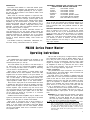
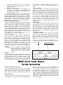
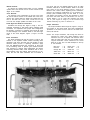
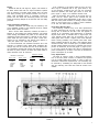
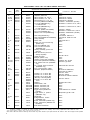
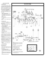
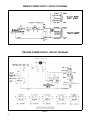
PM300 SERIES
OPERATING AND SERVICE MANUAL
Manufactured by
SHURE BROTHERS INC.
222 Hartrey Avenue
Evanston, Illinois 60204 U.S.A.
Copyright 1978, Shure Brothers Inc.
AL 407 (RE) 27A822
Printed in U.S.A.
PM300 SERIES SPECIFICATIONS
Amplifier Type . . . . . . . . . . . . . . . . . . . . . . . . . . . . . . . . . . . . . . . . All silicon transistor power amplifier
Power Output . . . . . . . . . . . . . . . . . 100 watts continuous (RMS) to 8 ohm load (see Figure 3, Page 4)
Voltage Gain . . . . . . . . . . . . . . . . . . . . . . . . . . . . . . . . . . . . . . . . . . . . . . . . . . . . . . . . . .
30 db (8 ohm load)
Sensitivity . . . . . . . . . . . . . . . . . . . . . . . . . . . . . . . . . . . . . . . . . . . 1.0 volt (8 ohm load, full rated output)
Frequency Response . . . . . . . . . . . . . . . . . . . . . . . . . . . . . . . . . . ±0.3 db, 100 Hz. to 10,000 Hz. (typical)
±1.5 db, 35 Hz. to 25,000 Hz. (typical)
lnput lmpedance . . . . . . . . . . . . . . . . . . . . . . . . . . . . . . . . . . . . . . . . . . . . . . . . . . . . . . . . . . . . .
Distortion . . . . . . . . . . . . . . . . . . . . . . . . . . . . . . . . . . . . . . . . . . . .
40,000 ohms
5% maximum at rated output at 1 KHz.
Hum and Noise . . . . . . . . . . . . . . . . . . . . . . . . . . . . . . . . . . . . . . . . . . . . . . . . . . . 80 db below rated output
Speaker Load Impedance . . . . . . . . . . Nominal 8 ohms (Operational 5.3 ohms minimum, see Page 4)
Dimensions . . . . . . . . . . . . . . . . . . . . . . . . . . . . . . . . . .
Weight: PM300
178 mm height x 429 mm width x 229 mm depth
(7 in. x 16-7/8 in. x 9 in.)
. . . . . . . . . . . . . . . . . . . . . . . . . . . . . . . . . . . . . . . . . . . . . . . . . . . . . . . . . . . . . 10 kg (22 lb)
PM300E and PM300E6 . . . . . . . . . . . . . . . . . . . . . . . . . . . . . . . . . . . . . . . . . . . . . 10.45 kg (23 lb)
Finish . . . . . . . . . . . . . . . . . . . . . . . . . . . . . . . . . . . . . . . . . . . . . . . . . . . . . . . . Gray, black and bright metal
Ambient Temperature Range . . . . . . . . . . . . . .
-7° C. to 43° C. (20° F. to 110° F.) without derating
Power Supply: PM300 . . . . . . . . . . . . . . . . . . . . . . . . . . . . . . . . . . . . . . . . . . . . . . . . . . . . . 120 volts, 60 Hz.
PM300E . . . . . . . . . . . . . . . . . . . . . . . . . . . . . . . . . . . . . . . . . . . . . 120/240 volts, 50/60 Hz.
PM300E6 . . . . . . . . . .100, 120, 140, 200, 220, or 240 volts, 50/60 Hz. switch selectable
Power Consumption . . . . . . . . . . . . . . . .40 watts with no signal; 160 watts with 1 KHz. signal and 100
watts output. 400 watts maximum.
FIGURE 1.
2
FIGURE 2.
DESCRIPTION
The Shure Power Master is a solid state booster power
amplifier capable of delivering 100 watts RMS to an 8-ohm
load. It has been designed specifically for use in conjunction with the Shure VA300-C and VA302-C Series Vocal
Master Amplifiers.
When used as a booster amplifier in conjunction with
the Shure Vocal Master Amplifier, the Power Master will
effectively increase area coverage, provide higher sound
levels and increase reserve power. Several Power Master
Amplifiers may be interconnected to provide even greater
power when required. This unit is ideally suited for use in
theatres, auditoriums, stadiums, college field houses, hotel
ballrooms, convention halls and wherever maximum coverage with reserve power is required.
Silicon transistors and similar solid-state devices are
used throughout the unit. The circuitry design protects the
solid-state components and eliminates the need for special
operating precautions. All components are of the highest
quality and are operated well within their respective tolerances to assure maximum stability under normal use
conditions.
The PM300 is listed by Underwriters’ Laboratories, Inc.,
and CSA Testing Laboratories listed as certified.
EQUIPMENT DESIGNED FOR USE WITH THE PM300
SERIES POWER MASTER AMPLIFIERS
Vocal Master Console
VA300-C
Vocal Master Console
VA302-C
Vocal Master Console
VA302E-C
Vocal Master Console
VA302E6-C
Vocal Master Speaker Column
VA300-S
Vocal Master Monitor Speaker
VA301-S
Rack Panel Mount Accessory
P300R
GUARANTEE: This Shure product is guaranteed in normal
use to be free from electrical and mechanical defects for a
period of one year from the date of purchase. Please retain
proof of purchase date. This guarantee includes all parts
and labor.
SHIPPING INSTRUCTIONS: Carefully repack the unit and
return it prepaid to the factory. If outside the United
States, return the unit to your authorized Shure Service
Center for repair. The unit will be returned to you prepaid.
SERVICE: If information or service should be required,
contact your local Shure Vocal Master dealer explaining
your difficulty in detail. In addition, the Shure factory
service department will be ready to assist you immediately upon request.
P M 3 0 0 S e r i e s Power Master
Operating Instructions
Input Connections:
Two parallel-wired input connectors are provided on the
rear panel of the Power Master. These connectors are
standard phone jacks (J1 and J2).
The Power Master may be driven to full rated output, to
an 8-ohm load, by any control-center amplifier, preamplifier, or microphone mixer which is capable of delivering
one volt across a 40,000-ohm load.
When using a Shure VA300-C or VA302 Series Vocal
Master Console as the control amplifier, connect the cable
supplied with the Power Master to the jack marked “To
Tape Recorder” on the VA300-C,* or to the jack marked
“Aux. Hi Level Output” on the VA302 Series Console, connect the other end of the cable to one of the jacks marked
“High Impedance Parallel Inputs” on the Power Master.
Since the two input jacks of the Power Master are wired
in parallel, one jack may be used as an auxiliary, high level,
output to feed the signal to another Power Master or other
booster amplifier. Tape recorders may also be fed from
one of the input jacks of the Power Master to the recorder’s
high impedance auxiliary input. (When used in this manner, the inputs are serving as a junction or “Y” connector
for the Power Master source.)
Additional Power Master Amplifiers may be added to the
system by interconnection from an input jack on one Power
Master to an input jack on another Power Master.
When used in conjunction with a Shure VA300-C or
VA302 Series Vocal Master Console, a setting of approximately “7” on the volume control (M6) of the Power Master
will provide equal output from the Vocal Master Console
and the Power Master when each is connected to equivalent speaker loads.
Up to a total of 15m (50 ft) of single conductor, shielded,
low capacitance cable (such as Belden #8401, 8410, or
8411) may be used to interconnect the Power Master
Amplifiers and the preamplifier. Where longer cable
lengths are required, it is suggested that the Power Master Amplifiers be driven by a 600-ohm line from a mixer
or control center amplifier, such as the Shure M67 or
M63, to avoid high frequency signal loss.
Output Connections:
Two parallel-wired output connectors are provided on
the rear panel of the Power Master. These connectors are
standard phone jacks (J3 and J4).
Full rated output of the amplifier is obtained when the
speaker load is 8 ohms (two VA300-S Speakers). Speaker
loads of less than 5.3 ohms (more than three VA300-S
Speakers) should not be used with this amplifier. No damage to the speakers or amplifier will occur, but thermal
shutoff of the amplifier may result. NOTE: With the amplifier driven at or near full power, pilot lamp will dim
or vary in brightness; this is a normal condition.
It should be noted that various speaker loads will affect
the output power of the amplifier. See Figure 3, Page 4 to
determine amplifier output power for the given speaker
load.
WARNING: Do not interconnect the speaker output jacks
or the speaker cables between two Power Master
Amplifiers or the Power Master and any other amplifier. This may result in damage to one or both amplifiers, and is not covered by the Guarantee.
*NOTE: Although most VA300-C Vocal Master Consoles have a “phonetype” “To Tape Recorder” jack, a limited number of early production Consoles have a “phono-type” jack for this function.
If an early Vocal Master Console is used, an adapter (such as
the Switchcraft No. 336A) should be added, or one end of the
connecting cable rewired with a phono plug (such as a Switchcraft No. 3502).
3
The Power Master does not use speaker output match-
ing transformers and thus avoids the distortion, power loss
and added weight inherent in such transformers. The
speaker output voltage is 28.3 volts, to an 8-ohm load, for
100 watts. This allows long speaker lines with wiring practices consistent with those used for 25-volt speaker lines.
Up to 30 m (100 ft) of #18 gauge two-conductor cable
(such as Belden #8452, 8478, 8460, or 8461) may be used
to connect from the Power Master to each 16-ohm
(VA300-S) speaker. Greater cable lengths require heavier
gauge wire to avoid appreciable power loss in the speaker cable. For 30 to 51 m (100 to 170 ft), use #16 gauge;
51 to 81 m (170 to 270 ft), use #14 gauge; and 81 to 128 m
(270 to 425 ft), use #12 gauge wire. To maximize the
power to each speaker, a separate cable should be used
to connect each speaker to the Power Master.
Speakers:
Selection of speakers for use in a vocal music system is
most critical. The factors which most significantly contribute to an outstanding vocal speaker system are correct
frequency range, distortion-free reproduction, and enough
sound power to fully penetrate the audience area.
The Shure VA300-S Speaker Column has been designed
to provide all of these features. It is recommended that
VA300-S Speaker Columns be used in pairs, each column
having a nominal impedance of 16 ohms, which provides
an impedance of 8 ohms when two are used. Each column
utilizes two special 10-inch speakers and four special 8inch speakers, and has a total speaker cone area of
2,310 cm² (358 in²) per column. The VA300-S Speaker
Column delivers virtually uniform penetrating power over
a 140° angle in the horizontal plane and a 65° angle in
the vertical plane. The rear-ported enclosure of the
VA300-S contributes to its highly directional pattern,
which is critical in achieving maximum audience penetration and reduction of feedback.
The Shure VA301-S Speaker Column is intended primarily for use as an “on-stage monitor.” While this speaker
meets all of the criteria for an excellent vocal system
speaker, its area of coverage is more localized than that
of the VA300-S. The nominal impedance of the VA301-S is
32 ohms, so that when used in conjunction with two
VA300-S Speaker Columns, the total system impedance
becomes 6.4 ohms. An integral volume control on the
VA301-S permits its use on-stage as a monitor at the highest possible sound level without feedback.
The following list shows various speaker combinations
and the resultant impedance loads which are suitable for
use with the Power Master:
QUANTITY and SPEAKER MODEL
1
1
1
1
2
2
4
1 VA300-S
2 VA300-S
3 VA300-S
1 VA301-S
2 VA301-S
3 VA301-S
4 VA301-S
5 VA301-S
6 VA301-S
VA300-S and 1 VA301-S
VA300-S and 2 VA301-S
VA300-S and 3 VA301-S
VA300-S and 4 VA301-S
VA300-S and 1 VA301-S
VA300-S and 2 VA301-S
IMPEDANCE
OHMS (NOMINAL)
16
8
5.3
32
16
10.6
8
6.4
5.3
10.6
8
6.4
5.3
6.4
5.3
FIGURE 3. Typical output power vs. speaker load impedance for the
Power Master
PM300 Power Requirements:
The PM300 Power Master is furnished with a three conductor power cable and three-prong plug. Connect the
power cable to an outlet which supplies 120 ±10% volts
A.C., 60 Hz power. The three-position toggle switch on
the front panel controls power to the amplifier. This
switch (S1) is also used to reverse line polarity, for minimum hum. If extension cords are required to supply
power to the PM300, a high quality #18 gauge or larger
cord should be used.
PM300E Power Requirements:
The PM300E Power Master is furnished with a threeconductor power cable without a plug. To connect a plug
to the power cable, attach the brown lead to the live (+)
terminal of the plug, attach the blue lead to the neutral (-)
terminal of the plug, and attach the green-yellow lead to
the earth-ground terminal of the plug.
The PM300E is factory wired for operation from a nominal 240 volt power supply. Connect the power cable to an
outlet which supplies 240 ±10% volts A.C., 50 to 60 Hz
power. The three-position toggle switch on the front panel
controls power to the amplifier. This switch (S1) is also
used to reverse line polarity, for minimum hum. If extension cords are required to supply power to the PM300E,
a high quality cable with conductors of 0.75 square millimeters cross-section or larger should be used.
An internal modification performed by competent personnel will allow the PM300E to be used with 120 volt, 50
to 60 Hz power. To change the power supply wiring for
120 volt operation, do the following:
1. UNPLUG THE AMPLIFIER POWER (MAINS) CABLE.
2. Remove the bottom plate as described on page 6.
3. W ith the amplifier upside down, note the six wires
from the power transformer T1.
4. Unsolder the yellow-black transformer lead wire and
the red-black transformer lead wire from their solderlug.
5. Resolder the yellow-black lead wire to the solder-lug
to which the all-black transformer lead wire is already
attached.
6. Resolder the red-black lead wire to the solder-lug
to which the green-black transformer lead wire is
already attached.
7. Reinstall the bottom plate.
8 . Remove the four screws from the nameplate on the
handle end of the amplifier. Turn the nameplate over
and reinstall. The nameplate nomenclature will now
be suitable for 120 volt use.
To change the PM300E back for use with 240 volt power,
reverse the above steps. Be careful to reconnect the yellowblack and red-black transformer lead wires to an UNUSEDUNGROUNDED solder-lug. A pictorial diagram of the transformer lead wire connections is located on the inside of
the bottom cover. The circuit diagram for both 120 volt and
240 volt operation is shown on page 10 of this manual.
PM300E6 Power Requirements:
The Model PM300E6 is supplied with a detachable threeconductor A.C. power (mains) cable without a connector
on the “mains” end. To attach a connector, connect the
brown conductor of the cable to the “live” terminal of the
connector, the blue conductor to the “neutral” terminal,
and the green-yellow conductor to the “earth” ( ) terminal.
The PM300E6 is designed to operate from 100, 120, 140,
200, 220, or 240 volts, 50 to 60 Hertz power (mains). An integral voltage-selector switch, located on the rear panel,
allows selection of the proper voltage.
As shipped from the factory, the PM300E6 is set to operate from 240 volts.
The A.C. fuseholder, located nearest the voltage-selector
switch, contains a 1.6 ampere slow-blow fuse (1.6 AT)
which should be used when the unit is operated from 200
through 240 volts. When operated from 100 through 140
volts, this fuse should be changed to a 3 ampere slow-blow
type (3.0 AT). The fuseholder located farthest from the
voltage-selector switch contains a 5 ampere (5.0 A) fuse
which should not be replaced by other values under any
circumstances. Each of the three fuses mentioned is a
5mm x 20mm type, and two of each value are supplied with
the unit.
CAUTION - DO NOT CHANGE VOLTAGE-SELECTOR
SWITCH SETTING OR ATTEMPT TO REPLACE FUSES WITHOUT FIRST DISCONNECTING THE A.C. POWER (MAINS)
CABLE.
Ventilation:
The Power Master has been designed to operate in a
horizontal position and minimum heat rise in the amplifier
will occur when mounted in this manner. Forty-four and
one-half millimeters (1¾ in.) minimum clearance should
be provided on front, back, and the top of the amplifier
to insure adequate air circulation. The Power Master may
be operated in an ambient temperature range from -7°C
to 43°C (20°F to 110°F) for continuous duty without derating.
Thermal Overload:
The Power Master is equipped with thermal sensing
switches on the heat-sinks of the output transistors. The
thermal switches are set to shut off AC power to the amplifier when a temperature of 90°C (194°F) is attained on the
heat-sinks; the switches will automatically recycle and
return AC power when the heat-sink temperature reaches
73°C (164°F). A thermal overload light (II), located on
the front panel of the Power Master, will indicate if thermal cycling has occurred. Thermal cycling may occur if
air is not allowed to circulate through the grilles of the
amplifier or if there is a prolonged short-circuit on the
speaker output.
Rack Mounting:
The accessory Rack Panel Kit, Model P300R, allows the
Power Master to be rack mounted in standard 19-inch audio
equipment cabinet racks. To insure adequate air circulation, a 44.5 mm (1¾ in.) space should be provided at the
top of the amplifier. The rack mounted Power Master
requires seven inches of height plus the air space. The
Rack Panel Kit is to be installed by qualified service
personnel only.
Connecting a VU Meter:
An external VU meter may be connected to the speaker
wires of the Power Master with a resistor attenuator (see.
Figure 4, Page 5). Use a true VU meter (such as Simpson
Model No. 1349) and three resistors connected as shown.
The resistors should be ½-watt carbon 5%, or 1% if available.
With an 8-ohm speaker load (two VA300-S) zero VU is
50 watts. Output power for other VU readings is shown in
the table below.
VU
Power to 8-ohm load
100 watts
50
25
10
5
+3
0
- 3
- 7
-10
FIGURE 4.
PM300 Series Power Master
Service Instructions
Amplifier Service (See Guarantee):
The Power Master uses components of the highest
quality, operating well within their respective ratings to
assure long life. CAUTION: There are no user serviceable
parts inside. Refer servicing to qualified service personnel.
Replacement Parts:
Parts that are readily available through local electronic
parts distributors are not shown on the accompanying Parts
List. Their values are shown on the circuit diagram. The
special custom made parts are shown on the Parts List.
The commercial alternates shown on the Parts List are
not necessarily equivalents, but may be used in the event
that direct factory replacements are not immediately available. To maintain the highest possible performance and
reliability, Shure factory replacement parts should be used.
When ordering replacement parts, specify the Shure Replacement Kit Number, description, product model number
and serial numbers.
5
Bottom Removal:
To remove the chassis bottom plate, turn the amplifier
upside down and remove the ten screws located at the
edges of the chassis.
Cover Removal:
For servicing of the components on the top of the chassis, remove the two screws on the handle end of the cover,
and the two screws within the plastic feet nearest the bottom on the other end of the cover. Uncoil the A.C. line
cord from the storage spindles and slide off the cover.
Small Signal and Predriver Transistors:
Transistors Q1 through Q3, Figure 6, Page 7, are mechanically supported by their leads. When replacing these
transistors, it is imperative that proper lead configuration
be followed. A minimum of soldering heat should be used
to avoid damage to the transistor. Refer to the lower right
corner of the circuit diagram, Figure 7, Page 9 for lead
code.
Driver Transistors:
The driver transistors Q4 and Q5, Figure 5, Page 6, are
located on the amplifier chassis. Before removing these
transistors, write down the lead color and location at each
transistor solder junction. If replacing transistors, apply
type 120 Wakefield thermal joint compound to each side
of the insulating wafer to provide good thermal transfer
from transistor to chassis. After replacement and before
connecting transistor leads, check transistors with an ohmmeter between case and chassis; there should be no continuity. Be sure that these transistors are not inverted in
the circuit; they are not identical devices. Q4 is an NPN
transistor, while Q5 is a PNP transistor. Refer to the lower
right corner of the circuit diagram, Figure 7, Page 9 for
terminal code. NOTE: When replacing driver transistors,
perform the following modification (if not already performed): place insulated tubing over the leads of a 3.3k,
½W resistor and solder it across the terminals to which
the white and black leads of transformer T2 are connected. Solder a .01 µF, 100V disc capacitor from terminal “A” (see Figure 6, Page 7) to the terminal strip
chassis mounting lug next to terminal “A”.
Output Transistors:
The output transistors Q6 through Q9, Figure 5, Page 6,
are located on the black finned heat sinks. Replacement
procedure is the same as that used for the driver transistors, Q4 and Q5.
NOTE: The output transistors, Q6 through Q9 must be
matched for current gain. When replacing output
transistors be sure to replace with devices which
have the same gain code and part number as the
original transistors. Shure transistors are coded
either by a color dot or a letter stamped on the top
of the transistor.
FIGURE 5.
6
Blue Dot
Red Dot
Orange Dot
Yellow Dot
Green Dot
=
=
=
=
=
A
B
C
D
E
Brown Dot
Pink Dot
Violet Dot
Black Dot
White Dot
= F
= G
= H
= J
= K
Diodes:
Diodes D5 and D6, see Figure 5, Page 6, are located on
the black finned sinks with the output transistors. Special
care is required to insulate these diodes from the heat
sink while providing good thermal transfer from sink to
diode. Heat shrinkable tubing or “spaghetti” should be
placed over the diode and connecting leads; the diode
should be securely clamped to the heat sink with the clamp
provided.
Check Transistors and Diodes:
Defective transistors and diodes may be located by use
of an ohmmeter. Polarity of the ohmmeter must be verified
before these checks are made.
With a known diode orientation, measure the diode resistance in the forward and reverse directions. The lowest
meter reading will establish the probe at the cathode end
(schematic symbol arrow points to cathode) as the “minus”
probe while the other probe will be “plus.” Some ohmmeters are not polarized in this manner with relation to
“volts plus probe” and “volts minus probe.”
To check transistors, the ohmmeter should be set to the
100-ohm or 1,000-ohm scale. Small signal transistors (Q1
through Q3) must be removed from the circuit before testing. Transistors mounted with screws (Q4 through Q9) may
be tested in place; however, the base and emitter leads to
these transistors must be removed.
-Ohmmeter -Connections“Plus” Lead
Collector
Emitter
Collector
Emitter
Base
Base
“Minus” Lead
Emitter
Collector
Base
Base
Collector
Emitter
Ohmmeter Reading
N.P.N.
Transistor
High
High
High
Low
Low
P.N.P.
Transistor
High
High
Low
Low
High
-
If all conditions in the above table are met, the transistor may be considered free of any gross defect; if any
of the following conditions are not met, the transistor
should be replaced. See lower right corner of circuit diagram, Figure 7, Page 9 for transistor terminal code,
With the ohmmeter “plus” probe on the anode end of a
diode, and the “minus” probe on the cathode end, the
ohmmeter should read approximately 2,000 ohms or less.
With the meter probes reversed, a reading of about 10,000
ohms or more should occur. If either of these conditions
is not met, the diode should be replaced.
Power Drain Resistor (RSEL):
The following condition may occur after replacement
of driver transistors Q4 and Q5, output transistors Q6
through Q9, or diodes D5 and D6. If the unit appears to
operate at an excessively high temperature or thermally
recycles after about 10 minutes with no signal input, the
“cold” standby power drain may be excessive (up to 20
watts higher than normal; a higher power drain indicates
further circuitry problems). The nominal power drain under
these conditions should be 40 watts; if the measured figure
exceeds 55 watts, insert a resistor (RSEL) in parallel with the
56-ohm resistor between the base of transistor Q4 and the
junction of diodes D5, D7 and D8 (figure 7, page 9). RSEL
(½ W, 10%) should be either 180 ohms to decrease the
power consumption by 20 watts, or 82 ohms to decrease the
power consumption by 30 watts.
Lamp Replacement:
The lamp 12, Figure 6, Page 7, which provides illumination of the front panel controls, is soldered and epoxied
into the molded plastic lamp socket in order to meet Underwriters’ Laboratories requirements. The assembly may
be removed by unsoldering the lamp leads at the terminal
strip and removing the screw that holds the socket to the
chassis.
FIGURE 6.
7
REPLACEMENT PARTS LIST FOR PM300 SERIES AMPLIFIERS
**
Replacement Kit Consists of:
Item
Repl.
Kit No.
Qty.
Part No.
C1
C2
D1-D4
D5, D6
D7, D8
F1
F1
RKC26
RKC27
RKC46
RKC50
RKC23
RKC62
- - -
1
1
4
2
1
5
-
86A631
86B631
86A406
86A410
86A409
80A159
80A258
F1
- - -
-
80B258
F2
F2
F3
RKC62
- - - - -
5
-
80A160
80A259
80A269
I1
I1
I2
J1-J4
M1
RKC45
RKC78
RKC34
RKC68
RKC82
1
1
2
1
1
80A79
80Z251
90A1463
95B446
95A510
M1
M1
RKC88
- - -
1
-
70A3071
90A1888
M2
RKC69
1
90A1681
M3
RKC70
1
32A627
M4
M5
M6
M7, M8
M7, M8
- - RKC39
RKC49
RKC72
- - -
1
4
3
1
-
90BC2600
65A685
90B2285
95A500
95A604
M9
- - -
-
95A568
M10
Q1-Q2
- - RKC9
4
90A1522
86A349
Q3
Q4
Q5
RKC53
RKC55
RKC54
1
1
1
Q6-Q9
- - -
-
R1
R2
R3-R6
R7
R8
S1
RKC47
RKC73
- - - - - - RKC61
1
1
1
86A333
86A338
86A339
86B339
86A332*
86B332*
45A38
46A025
45EC439B
45EC209B
45EC129B
55A72
S1
- - -
-
55A98
S2, S3
S4
RKC37
- - -
1
-
95A551
55A99
T1
T1
RKC35
RKC147
1
1
51A215
51A241
T2
RKC28
1
51A217
Description
Capacitor, 2500 x 100
Capacitor, 4000 x 60
Silicon Rectifier, 3A., 200 V.
Silicon Rectifier, ½A., 100 V.
Zener Diode, 3.6 V., 1 W., 5%
A.C. Fuse (PM300 and PM300E)
A.C. Fuse (PM300E6 only)
for 200-240 volts
A.C. Fuse (PM300E6 only)
for 100-140 volts
D.C. Fuse (PM300 and PM300E)
D.C. Fuse (PM300E6 only)
Wired in A.C. Fuse (PM300 only)
Pilot Lamp (PM300 only)
Pilot Lamp (PM300E and PM300E6)
Lamp Assembly
Phone Jack
3 Wire A.C. Line Cord and Plug
(PM300 only)
Line Cord (PM300E only)
Line Cord and Connector
(PM300E6 only)
Housing Assembly (Cover and
Spindle)
Knob and Screw (Line Cord
Storage Spindle)
Handle and Nuts
Bumper (Plastic Foot)
Volume Control Knob Assembly
Fuse Holder (PM300 and PM300E)
Fuse Holder 5x20 mm (PM300E6
only)
A.C. Chassis Power Connector
(PM300E6 only)
Input Interconnecting Cable
Transistor (Replaces 86A327)
Transistor 110 V. BVCEO Min.
Transistor 110 V. BVCEO Min.
Transistor 105 V. BVCEO Min.
(Mutually Interchangeable)
Transistor 110 V. BVCEO Min.
150 W.
Resistor
Potentiometer, 50K.
Resistor, 0.43 ohms, 5 W.
Resistor, 0.20 ohms, 5 W.
Resistor, 0.12 ohms, 5 W.
Toggle Switch (PM300 and
PM300E)
Toggle Switch, 2 position
(PM300E6 only)
Thermostat
Voltage-Selector Switch
(PM300E6 only)
Power Transformer (PM300 only)
Power Transformer (PM300E and
PM300E6)
Feed back Transformer
Commercial Alternate
None
None
Motorola No. 1N4721
Motorola No. 1N4002
Motorola No. 1N4729A
Littelfuse 3AG/3A/SB (Slo-Blo)
Wickmann 5 x 20mm 1.6 AT, 250 V.
Wickmann 5 x 20mm 3.0 AT, 250 V.
Littelfuse 3AG/5A
Wickmann 5 x 20mm 5.0 A, 250 V.
Bussmann MDV/5A/SB (Slo-Blo)
Pig-Tail
Leecraft No. 36N1311-6
Leecraft No. 36HN-1311-7W
None
Switchcraft No. 11
None
None
None
None
None
Bud No. H9115
None
None
Littelfuse No. 341001
Schurter Type FEB
Switchcraft No. EAC-301
None
Motorola No. MPS-6521,
Texas Inst. No. 2N3711
RCA No. 40349
RCA No. 2N3441
Motorola No. 2N3741 Selected
RCA No. 2N3773
Workman No. FRT-2
None
None
None
None
Cutler-Hammer No. 7563K5
Marquardt Type No. 0132
None
None
None
None
None
NOTE: The Commercial Alternates shown above are not necessarily equivalents, but may be used in the event that direct factory replacements are not
immediately available. To maintain the highest possible performance and reliability, Shure Factory Replacement Parts should be used.
*When ordering 86A332 or 86B332, specify current gain code. See page 6.
**Parts listed as RKC Kits should be ordered by that kit number. Any orders received for piece parts where RKC Kit number is shown will be shipped in RKC quantities.
8
NOTES TO THE CIRCUIT DIAGRAM
PM300 CIRCUIT DIAGRAM
D.C. Voltage Measurements:
Check the DC voltages before checking AC voltages because transistors Q2 through Q9 are direct coupled and
any deviation from the nominal voltages will affect the AC
voltages. The four key DC voltages are +94, +20, the
emitter of Q1, and the split voltage at the junction of R3,
R5, R7, and R8. If these four key DC voltages are correct,
then proceed with the AC voltage measurements.
The numbers within the symbol
on the circuit diagram denote the DC voltage at that point with the following test condition:
1. Voltages measured at points indicated with respect to
chassis, unless otherwise specified.
2. Line voltage PM300: 120 V. 60 Hz.; PM300E: 120/240 V.
50/60 Hz.; PM300E6: 100, 120, 140, 200, 220, or 240 V.
50/60 Hz.
3. No input signal applied.
4. DC voltage measurements may vary ±20% from the
values shown.
5. Measured with a VTVM of 11-megohms input impedance.
A.C. Voltage Measurements:
The numbers within the symbols
on the circuit
diagram denote the AC voltage at that point with the following test conditions:
1. Voltages measured at points indicated with respect to
chassis, unless otherwise specified.
2. Line voltage as specified above.
3. 1,000 Hz. signal applied to one of the high impedance
parallel inputs at 300 millivolts (.3 volts).
4. Measured with an AC VTVM of 1.0 megohms or greater
input impedance.
5. Noninductive load of 8 ohms, 200 watts connected to
speaker output jack.
6. Volume control set to maximum.
7. AC voltage measurements may vary ±20% from the
values shown.
Shure part numbers are not shown in the Parts List, accompanying the circuit diagram, if parts are readily available through local electronic parts supply distributors. In
these instances, the circuit diagram will show the values of
the standard parts.
All capacitor values are shown in microfarads. All nonelectrolytic capacitors are to be 100 volts or more unless
otherwise specified in the circuit diagram. Electrolytic
capacitors are shown in microfarads and volts.
All resistor values are shown in ohms. Resistors are all
to be 10% tolerance unless specifically noted on the circuit diagram.
All resistors are ½ watt unless otherwise specified.
The following ground symbol
denotes chassis ground:
Ohmmeter Measurements:
With the A.C. line cord unplugged and the power switch
in the “OFF” position, the following ohmmeter measurements may be made.
1. B+ to ground approximately 100 ohms.
2. Ohmmeter plus probe to the junction of R3, R5, R7, and
R8, ohmmeter minus probe to ground; greater than 120
ohms.
3. Ohmmeter plus probe to B+, ohmmeter minus probe to
the junction of R3, R5, R7, and R8: greater than 120
ohms.
4. To test transistors and diodes, see page 7.
NOTES:
1. ALL CAPACITORS IN MFD AND 100 VOLTS OR MORE
UNLESS SHOWN. ELECTROLYTIC CAPACITORS SHOWN
IN MFD x VOLTS.
2. ALL RESISTORS 10%, ½ WATT, UNLESS OTHERWISE
INDICATED. R3 THRU R8 10%, 5 WATT.
3. THE FOLLOWING SYMBOLS DENOTE:
DC VOLTAGE
AC VOLTAGE
WITH RESPECT TO CHASSIS UNLESS OTHERWISE
SHOWN.
4. RSEL MAY BE 180 OR 82 OHMS, OR NOT USED, DEPENDING
ON POWER DRAIN (SEE PAGE 7).
FIGURE 7.
9
PM300E POWER SUPPLY CIRCUIT DIAGRAM
FIGURE 8.
PM300E6 POWER SUPPLY CIRCUIT DIAGRAM
FIGURE 9.
10