1
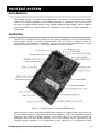
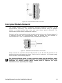
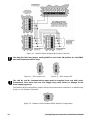
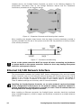
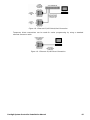
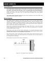
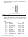
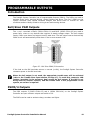
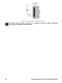
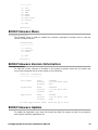
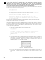
PRT-CTRL
Integrated System Controller
Installation Manual
CONTENTS
Protégé System
Introduction
.........................................................................................
Controller
............................................................................... ..................
Features
............................................................................... ..................
Controller Specifications
.............................................................................
Protégé System Management Suite
..........................................................
Protégé Modules
.......................................................................................
Installation
Package Contents
........................................................................................
Location and Mounting
...........................................................................
Cabinet Tamper Switch
............................................................................
Earth Ground Connection
...........................................................................
AC Power
...............................................................................................
Backup Battery
.......................................................................................
Battery Charging Current
...............................................................................
Status Indicator Output
...........................................................................
Encrypted Module Network ...............................................................................
Telephone Dialler
........................................................................................
Expansion Connector
..............................................................................
Ethernet 10/100 Network Interface
.........................................................
Zone Inputs
Introduction
......................................................................................
Zone Inputs
.....................................................................................
Trouble Zone Inputs
............................................................................
Programmable Outputs
Introduction
.......................................................................................
Bell/Siren PGM Outputs
............................................................................
PGM 3 and 4 Outputs
.............................................................................
Configuration Switch
Introduction
..........................................................................................
Configuration Switch
...........................................................................
Factory Default Controller .............................................................................
Status Indication
Introduction
.......................................................................................
Status Indicator
..........................................................................................
Fault Indicator
.......................................................................................
Charge/Test Indicator
.............................................................................
Auxiliary OK Indicator
...........................................................................
AC OK Indicator
........................................................................................
Protégé System Controller Installation Manual
3
3
3
4
4
5
5
7
7
7
7
8
8
9
10
11
11
13
13
14
16
16
16
17
19
19
19
19
21
21
21
21
22
22
22
22
22
22
22
1
5V Isolated Power Indicator
Bell 1/Bell 2 Indicators
Network RX/TX Indicator
Ethernet Link Indicator
Ethernet 10/100 Indicator
Ethernet Data Indicator
.....................................................................
...........................................................................
...........................................................................
...........................................................................
.................................................................
............................................................................
24
Controller BIOS Operation
Introduction
.....................................................................................
Entering BIOS Operation
.................................................................
BIOS Serial Communication
.................................................................
BIOS Ethernet TCP/IP Communication
.........................................................
BIOS Main Menu
.....................................................................................
BIOS Setup Menu
.....................................................................................
BIOS Testing Menu .......................................................................................
BIOS Firmware Menu
...........................................................................
BIOS Firmware Version Information
..........................................................
BIOS Firmware Update
..........................................................................
.....................................................................................
2
30
31
Warranty
Introduction
Contact
24
24
24
25
26
26
26
27
27
27
30
Ordering Information
Product Codes
23
23
23
23
23
23
.....................................................................................
................................................................................................
31
31
Protégé System Controller Installation Manual
PROTÉGÉ SYSTEM
Introduction
The Protégé System is a powerful integrated alarm and access control management system
designed to provide integration with building automation, apartment complex control and
HVAC in one flexible package. Communicating through a proprietary high speed protocol
across an encrypted RS-485 network using modular-based hardware design, system installers
have the flexibility to accommodate any installation from small or large, residential or
commercial.
Controller
The PRT-CTRL Protégé System Controller is the central processing unit of the Protégé System.
The Protégé System Controller communicates with all system modules, stores all
configuration and transaction information, process's all system communication and reports
alarms and system activity to a monitoring station or remote computer.
Figure 1 – Protégé System Controller PCB Reference
Flexible module network architecture allows large numbers of modules to be connected to the
RS-485 Module Network. Keypad Interface, Zone Expander, PGM (Programmable Outputs)
Expander and Reader Interface modules communicate with the controller through the
encrypted secure RS-485 Module Network. Up to 250 modules can be connected to the
Protégé System Controller in any combination to the network up to a distance of 900M
Protégé System Controller Installation Manual
3
(3000ft). Communication beyond this distance requires the use of a RS-485 Network
Extender.
Securing a network prevents the removal, substitution or addition of modules to the module
network ensuring system integrity.
Features
•
•
•
•
•
•
•
•
•
•
Secure Encrypted RS-485 Module Communications
Onboard Ethernet 10/100M Interface
16 On Board Zone Inputs
2 Bell/Siren PGM Outputs
1.8A Switching Power Supply
Intelligent Battery Charge Algorithm and Monitoring
Upload Download for programming and control of local and remote sites
Online and Remote upgradeable firmware
2400Bps Modem Communication
All Major Alarm Reporting Formats
Controller Specifications
The following specifications are important and vital to the correct operation of the
PRT-CTRL Protégé System Controller. Failure to adhere to the specifications will
result in any warranty or guarantee that was provided becoming null and void.
Integrated Control Technology continually strives to increase the performance of its products
and as a result the specifications may change without notice. It is recommended that you
always consult www.integratedcontroltechnology.com for the latest documentation and
product information.
Power Supply
AC Input Voltage
Operating Current
DC Output (Auxiliary)
Battery Charging
Battery Low
Battery Restore
Communication
Ethernet
RS-485
Modem
Outputs
Bell Outputs
Low Current PGM Outputs
Status Output
Inputs
Zone
Tamper
Trouble Zone
4
16VAC 50/60Hz @ 40VA (Max)
280mA (Typical)
1.2A (Max)
350mA/700mA
10.5VDC
11.5VDC
10/100 Auto Negotiation
Isolated Module Network
Security Reporting
Upload Download 2400Bps
Dial Up Networking
2 (PGM Outputs)
1.8A (Max), 2A Electronic Shutdown
Load 2 8 Ohm 20W Siren
2 50mA (Max) Open Collector
50mA (Max) Open Collector
16 (500ms to 40sec Input Speed)
1 (Normally Closed)
64
Protégé System Controller Installation Manual
Dimensions
PCB Dimensions
Enclosure
Temperature
Operating
Humidity
Storage
Miscellaneous
Expansion Connection
183mm X 234mm
7.2" X 9.2"
330mm X 406mm X 89mm
13" X 16" X 3.5"
5˚- 55˚ Celsius
41˚ - 131˚ Fahrenheit
0%-85% (Non-Condensing)
-10˚- 85˚ Celsius
14˚ - 185˚ Fahrenheit
Yes (Memory / Communication)
It is important that the unit is installed in a dry cool location that is not affected by
humidity. Do not locate the unit in air conditioning or a boiler room that can exceed
the temperature or humidity specifications.
The isolated communications interface on the Protégé System Controller uses full
galvanic isolation to prevent ground loop noise and cross phase ground differential.
This is a very important feature of the product family and the correct connection of
power to this isolated section will ensure the correct operation of the
communications network. Failure to apply power to the communication interface
will prevent the operation of the communication interface.
Protégé System Management Suite
The Protégé SMGT application is a Windows 2000/XP Professional Integrated Access Control
and Alarm Management system designed for any configuration from single site, single
controller applications up to the global multi-national corporations using multiple site, multiple
controller installations.
The Protégé SMGT application is designed for efficient configuration and management of your
Protégé installation. Special built in features and the quick-start kit will get your system up
and running in minutes.
Protégé Modules
The Protégé System can be expanded to accommodate large numbers of modules using the
encrypted RS-485 network. Modules that are currently available are listed below. Visit the
Integrated Control Technology website www.integratedcontroltechnology.com for the latest
Protégé module and product information.
Alphanumeric LCD User Interface (PRT-KLCD)
The Protégé LCD User Interface Keypad is the interface between the user and the
Protégé System. All programming and end user functions can be performed using the
LCD Keypad. The 32 character alphanumeric display uses easy to read messages and
menus to guide users through the systems operation. The LCD Keypad also adds two
zones (four zones in multiple zone configuration) and one PGM to the Protégé System.
16 Zone Expansion Module (PRT-ZX16)
Extends the Protégé System with the addition of 16 Zones and 4 Programmable
Outputs (PGM's). Operates from 16VAC with onboard power supply and isolated
communication interface.
Protégé System Controller Installation Manual
5
16 Zone Standard Expansion Module (PRT-ZXS16)
Extends the Protégé System with the addition of 16 Zones and 1 Programmable
Output (PGM). Operates from 12VDC network connection. No onboard power supply.
16 PGM Expansion Module (PRT-PX16)
Extends the Protégé System with the addition of 16 Programmable Outputs (PGM's)
(16 7A FORM C Relays). The PRT-PX16 can be connected to the slave communications
interface of the PRT-RDI2 2 Reader Expansion Module for FULL monitored elevator
control with the addition of the PRT-DRI Destination Reporting Interface Optical Input
Module.
16 PGM Standard Expansion Module (PRT-PXS16)
Extends the Protégé System with the addition of 16 Programmable Outputs (PGM's)
(16 20mA Open Collector Outputs). Operates from 12VDC network connection. No
onboard power supply.
Ethernet Intelligent 2 Reader Expansion Module (PRT-RDE2)
Communicating over a high speed interface using 10/100 Ethernet, interface
connection for two card readers, either Wiegand or Magnetic Stripe formats. Four
Wiegand Card Readers can be connected in Multiple Card mode. The 2 Reader Ethernet
Expansion Module also adds 8 Zones and 8 Outputs to the Protégé System. Some of
the outputs on the PRT-RDE2 have specific access control functions and can be used as
zones in the Protégé alarm processing functions.
Intelligent 2 Reader Expansion Module (PRT-RDI2)
Adds the interface connection for two card readers, either Wiegand or Magnetic Stripe
formats. Four Wiegand Card Readers can be connected in Multiple Card mode. The 2
Reader Expansion Modules also adds 8 Zones and 8 Outputs to the Protégé System.
Some of the outputs on the PRT-RDI2 have specific access control functions and can
be used as zones in the Protégé alarm processing functions.
Mini 2 Reader Expansion Module (PRT-RDM2)
Adds the interface connection for two card readers, either Wiegand or Magnetic Stripe
formats. Four Wiegand Card Readers can be connected in Multiple Card mode. The 2
Reader Expansion Modules also adds 6 Zones and 8 Outputs to the Protégé System.
Some of the outputs on the PRT-RDM2 have specific access control functions and can
be used as zones in the Protégé alarm processing functions.
Analog 4 Channel Input Expansion Module (PRT-ADC4)
Protégé allows the connection of the latest building automation technology and
completely integrated building automation solutions. Adds 4 Analog Inputs (4-20mA or
0-10V) allowing the connection of numerous industrial automation sensors. The Analog
Input Expansion Modules also adds 4 PGM Outputs to the Protégé System.
Analog 4 Channel Output Expansion Module (PRT-DAC4)
Protégé allows the connection of the latest building automation technology and
completely integrated building automation solutions. Adds 4 Analog Outputs (4-20mA
or 0-10V) allowing the connection of numerous industrial automation outputs including
air damper and sun louver controls as well as analog flow valves. The Analog Output
Expansion Modules also adds 4 PGM Outputs to the Protégé System.
6
Protégé System Controller Installation Manual
INSTALLATION
Package Contents
When receiving the PRT-CTRL Protégé System Controller you should find the kit contains the
items listed below. The kit type is clearly labelled on the packaging. Please note that if you do
not have the correct contents contact your distributor immediately.
PRT-CTRL-PCB
Contents:
Protégé System Controller PCB Only
Controller Printed Circuit Board
Plastic Mounting Standoffs
36 1K Ohm Resistors
Red/Black Backup Battery Wires
Location and Mounting
The Protégé System Controller is available as a PCB Only (Printed Circuit Board) or complete
unit supplied with a metal cabinet. It is recommended that the cabinet provided be used
where possible, as this provides the best mounting and installation solution as well as the
required cable entry and termination space.
When installing the Protégé System Controller ensure that there is adequate clearance around
all sides of the enclosure and air flow to the vents of the enclosure are not restricted.
It is recommended to install the Protégé System Controller in a location that will facilitate
easy access for wiring. It is also recommended that the Protégé System Controller is installed
in electrical rooms, communication equipment rooms, closets or in an accessible area of the
ceiling.
1. Insert the plastic stand-offs in to the locations to mount the PCB board.
2. Calculate the location and position of the enclosure and mark the holes for the keyhole
points in the top left and right locations. This will allow you to screw in the screws and
then hang the box on them adjusting the location to suit.
3. Ensure a solid fixing point and screw in the two screws. Before tightening the top
screws insert the tamper bracket in the slot provided on the right side of the
enclosure.
4. Fix the enclosure securely using the remaining mounting holes on the bottom left,
right and centre of the enclosure.
5. If you are extending the System Controller by the addition of a communications
module or memory interface insert the 4 extended nylon standoffs through the rear of
the controller PCB as shown in the interface board manual.
6. Insert the PCB in to the enclosure and mount using the plastic standoffs inserted
during step one.
It is recommended to install the enclosure when the circuit board is NOT installed
on the plastic stand-offs as this will reduce the risk of damage caused by debris
during the installation.
Cabinet Tamper Switch
The enclosure tamper input signals to the monitoring station or remote computer that an
enclosure has been opened. The tamper input switch should be mounted into the steel
Protégé System Controller Installation Manual
7
bracket provided and connected to the tamper connection terminals as shown in the diagram
below.
Figure 2 - Tamper Input
Earth Ground Connection
The controller has a connection for earth ground. For best results a cold water pipe should be
used with a pipe wiring clamp. If a cold water pipe is not available connect to a suitable
ground connection in the installation.
A minimum 14AWG solid copper wire should be used from the controller's earth connection
point to the clamp on the cold water pipe. If other earth clamps are present at the same
connection point connect the clamp below the existing units.
Figure 3 - Controller Main Earth Ground Connections
The telephone communication dialler contains a separate earth connection. Do not
loop the earth connection from the dialler to the earth of the controller. A separate
connection should be connected to the same earth point.
AC Power
The controller should be supplied by a dedicated electrical power source rated for a minimum
10Amp Load and have a dedicated circuit breaker. Do not use a switch controlled breaker or a
switched electrical point to supply electrical power. Connect the primary of a 16.5VAC,
50/60Hz, 40VA Transformer to the electrical circuit and run the secondary to the AC input on
the controller terminals.
8
Protégé System Controller Installation Manual
Figure 4 - AC Transformer 16VAC, 50/60Hz, 40VA MAX
Specific regional regulations may allow the transformer to be mounted inside the enclosure.
In this case wire the electrical circuit to the electrical termination point inside the enclosure
and the secondary wires of the transformer to the AC Input on the controller. The earth wire
should be routed to the terminal on the controller PCB when using an internal transformer.
Termination of wiring to the controller while power is applied or the battery is
connected may cause serious damage to the controller and will VOID ALL
WARRANTEES OR GUARANTEES. Power the unit ONLY after all wiring, configuration
and jumper settings are completed.
Backup Battery
It is recommended that a minimum of a 4Ah battery is used as the main backup battery.
From the accessory bag provided, connect the RED and BLACK battery termination wires to
the B+ and B- terminals. Connect the spade terminals to the battery as shown below.
Connection of the battery in reverse will not damage the System Controller but will cause the
battery fuse (5A Fast Blow) to blow and require replacement.
Figure 5 - Battery Connection
The battery test procedure uses a special algorithm to prevent deep discharge and increase
battery endurance. A dynamic battery test is performed every ten minutes (default) when AC
power is present. A battery trouble zone alarm will be generated if the battery is either
disconnected or shows poor capacity. Battery fault conditions will activate the battery trouble
zone.
Protégé System Controller Installation Manual
9
If AC is not present the Protégé System Controller will monitor the battery for a low voltage
level and will activate the battery trouble zone. The next dynamic battery test will occur 30
minutes after AC power has been restored. This delay allows the battery to achieve optimal
charging during the first 30 minutes that power has been restored to the unit. Once the first
test is completed the dynamic testing will return to the programmed value (default 10
minutes).
When power is first applied to the Protégé System Controller a dynamic battery test will be
performed after 30 seconds, this allows the status and condition of the battery to be
detected. On completion of this first test the default testing period of 10 minutes will be
resumed, this is a programmable setting in the system controller panel options. The test
period can be changed as required by setting the battery test time in the controller
configuration menu.
Only attach standard Lead Acid Batteries. DO NOT connect the Battery Wires or B+
and B- terminals of the controller to any other ancillary device (Siren, Lock or Mag
Clamp etc). Connection may cause erroneous faults or serious damage to the
controller and will VOID ALL WARRANTEES OR GUARANTEES.
Battery Charge Current Setting
Battery charging can be controlled by the charging configuration option programmed in the
Panel Options menu (Default) or by the configuration of the battery charging jumper. To
configure the controller manually for the charge current, select the appropriate battery
current limit setting using the jumper as shown in the figures below.
Figure 6 - Battery Charge 350mA Setting
Figure 7 - Battery Charge 700mA Setting
Status Indicator
The status output will activate according to the status indicator on the Protégé System
Controller and can be used to provide signalling or indication of the system controller status
outside the enclosure. The following diagrams show the connection of an LED indicator to the
status output.
10
Protégé System Controller Installation Manual
Figure 8 - External Status LED Connection
Encrypted Module Network
The Protégé System Controller incorporates technically advanced encrypted RS-485
communications technology. The isolated communications interface offers full galvanic
isolation to prevent ground loop noise and cross phase ground differential. The
communication offers superior interference immunity.
Connection of the communications should be performed according to the following diagram. It
is important that the 12V Communications power be supplied from the controller or
controlling device or from an independent battery backed power supply unit.
Figure 9 - Standard Communications Connection
Always connect the controllers NA and NB terminals to the NA and NB terminals of the
expansion devices and keypads as shown. The N+ and N- must go to a 12V power supply
source as shown in the following diagram.
The following diagram shows a power connection taken from the Auxiliary Power
Outputs on the controller’s zone terminals. It is recommended to only use this
connection for smaller systems where limited power is required. For larger
installations use a separate power supply.
Protégé System Controller Installation Manual
11
Figure 10 - Network Power Supplied By System Controller
The EOL (End Of Line) jumper setting MUST be set in the ON position for the FIRST
and LAST expansion device only.
Figure 11 - EOL Jumper ON
Figure 12 - EOL Jumper OFF
The 12V N+ and N- Communication input must be supplied from only ONE point.
Connections from more than one 12V supply may cause failure or damage to the
units supplying power.
The Network BIAS configuration jumpers allow the communication network to be biased using
a high or Low (Default) resistance.
Figure 13 - Network LOW resistance BIAS (Default) Configuration
12
Protégé System Controller Installation Manual
Figure 14 - Network HIGH resistance BIAS Configuration
Biasing the network with the controller in the LOW setting is the default
configuration.
Only under special circumstances should the BIAS jumpers be
changed from Factory Default.
Telephone Dialler
The Protégé System Controller provides the ability to communicate alarms and
upload/download information with remote systems using the onboard 2400Bps modem. The
telephone lines can be connected directly to the Protégé System Controller using the onboard
telephone connection terminals.
The secondary telephone line terminals can be used as a backup telephone line. If the
Reporting Service fails and the Controller is unable to communicate with the central station
through the primary telephone line, the Protégé System Controller will switch to the second
line (if programmed) and repeat the communication process (refer to the Service
programming section in the Protégé System Reference Manual for settings that relate to
reporting and communication).
Figure 15 - Telephone Line Connection
It is recommended that the earth connection for the telephone and main power
supply (refer section Earth Ground Connection in Page 8) earth be run separately
and should be terminated on the cold water pipe or similar grounding point within
the installation.
The secondary telephone connection is optional and only required if the secondary
line option is enabled. For more information refer to the Protégé System Controller
Reference Manual.
Expansion Connector
The Protégé System Controller includes a 40 way expansion connector that is used to connect
serial communication, parallel, memory and special function interface devices. Connect the
Protégé System Controller Installation Manual
13
interface card to the Protégé System Controller as shown in the following diagrams. For
configuration information refer to the Protégé Reference Manual and the Installation
Instructions provided with the interface device.
Figure 16 - Expansion Connector and Mounting Hole Location
When installing the daughter board ensure that the plastic mounting hardware provided is
correctly inserted from the rear of the system controller PCB. Pay attention to the key location
of the 40 Way Connector.
Figure 17 - Connection and Mounting
Power to the system controller MUST be turned off when connecting any hardware
or system device to the system controller. Failure to do so may damage the system
controller and expansion device.
Ethernet 10/100 Network Interface
The communication between the Protégé SMGT System Management Suite and the Protégé
System Controller uses a 10/100 ethernet network operating the TCP/IP protocol suite. The IP
address of the controller can be configured using the LCD Keypad Terminal. The default IP
address is set to a static IP address of 192.168.1.2 with a subnet mask of 255.255.255.0.
These IP address settings are commonly used for internal networks.
Installing the Protégé System Controller on an active network requires knowledge
of the configuration and structure for the network. Always consult the network or
system administrator and ask them to provide you with a fixed IP address that can
be assigned to the Protégé System Controller.
When installing an Ethernet connection the Protégé System controller should be interfaced
using a standard segment (<100M in length) and should be connected to a suitable ethernet
hub or switch.
14
Protégé System Controller Installation Manual
Figure 18 - Ethernet 10/100 Switch/Hub Connection
Temporary direct connections can be used for onsite programming by using a standard
ethernet crossover cable.
Figure 19 - Ethernet 10/100 Direct Connection
Protégé System Controller Installation Manual
15
ZONE INPUTS
Introduction
The Protégé System Controller has 16 Zone Inputs. The controller also monitors 64 trouble
zones used to report trouble conditions. A trouble zone represents a trouble condition within
the system. The trouble zone will open or go in to alarm when that trouble condition is
present, and close or return to normal when the trouble condition restores. As an example
trouble zone CP001:01 will open or go in to alarm when the tamper input on the system
controller is open.
The Protégé System Controller can monitor and control thousands of zone and trouble zone
inputs by using the expansion modules.
Zone Inputs
The Protégé System Controller can monitor the state of up to 16 zone inputs such as
magnetic contacts, motion detectors and temperature sensors. Devices connected to these
zones can be installed to a maximum distance of 300m (1000ft) from the Controller when
using 22 AWG. The Controller supports normally opened and normally closed configurations
with or without EOL resistors as explained below.
Zones can be programmed from the Protégé LCD Keypad (PRT-KLCD) or using the Protégé
System Management Suite (PRT-SMGT). CP001:01 to CP001:16 represent Zone 1 to Zone 16
on the Protégé System Controller.
When using a zone with the EOL resistor configuration, the controller generates an alarm
condition when the state of a zone is toggled and generates a tamper alarm condition when a
wire fault (short circuit) or a cut (tampered) in the line occurs.
When using the EOL resistor configuration, the EOL resistor option must be turned on for the
zone(s) so that the tamper and shorted states can be monitored (refer to Zones Section in
the Protégé Reference Manual).
Zones default to require the EOL resistor configuration.
Figure 20 - EOL Resistor Zone Configuration
16
Protégé System Controller Installation Manual
Each zone input can use a different input configuration. To program a large number of zones
with a certain configuration use the Multiple Selection feature in the Protégé System
Management Suite application.
When using the No Resistor configuration, the Controller only monitors the opened and closed
state of the connected input device generating the alarm and seal conditions.
Figure 21 - No EOL Resistor Zone Configuration
Trouble Zone Inputs
Each Controller can monitor up to 64 local trouble zones. Trouble zones are used to monitor
the status of the Controller and in most cases not physically connected to an external zone.
For example, trouble zone CP001:03 is used to monitor the Controller’s backup battery
voltage and warn the Controller that the battery is disconnected or voltage is too low. This
can then be used to report a message to a monitoring station, remote computer, keypad or
siren.
The following table details the trouble zones that are configured in the system controller. The
trouble type and group define the trouble that is generated by the trouble zone when it is
activated.
Zone Number
Description
Type
Group
CP001:01
CP001:02
CP001:03
CP001:04
CP001:05
CP001:06
Module Tamper
AC failure
Low Battery
Real Time Clock Not Set
Service Report Test
Service Report Failure To
Communicate
Phone Line Fault
Auxiliary Failure
Bell 1 Cut/Tamper
Bell 2 Cut/Tamper
Bell 1 Over Current
Bell 2 Over Current
Module Communication
Module Network Security
Expansion Device Missing
Communication Port 1 Fault
Communication Port 2 Fault
System Tamper
Power Fault
Power Fault
RTC/Clock Loss
*
Reporting Failure
System
General
General
General
*
General
Phone Line Lost
Power Fault
Bell/PGM Fault
Bell/PGM Fault
Bell/PGM Fault
Bell/PGM Fault
Module Loss
Module Security
Hardware Fault
Hardware Fault
Hardware Fault
General
General
General
General
General
General
System
System
System
System
System
CP001:07
CP001:08
CP001:09
CP001:10
CP001:11
CP001:12
CP001:13
CP001:14
CP001:15
CP001:16
CP001:17
Protégé System Controller Installation Manual
17
CP001:18
CP001:19
CP001:20
CP001:21
CP001:22
CP001:23
CP001:24
CP001:25
CP001:26
CP001:27
CP001:28
| || |
CP001:64
18
Ethernet Hardware Fault
Ethernet Link Lost
DVAC Line Fault/Polling Error
ModBUS Communication Fault
Protégé SMGT Remote Access
Installer Logged In
Service 1 Stopped
Service 2 Stopped
Service 3 Stopped
Service 4 Stopped
Reserved
|
|
Reserved
Hardware
Hardware
Hardware
Hardware
Hardware
Hardware
Hardware
Hardware
Hardware
Hardware
*
|
*
Fault
Fault
Fault
Fault
Fault
Fault
Fault
Fault
Fault
Fault
System
System
System
System
System
System
System
System
System
System
*
|
*
Protégé System Controller Installation Manual
PROGRAMMABLE OUTPUTS
Introduction
The Protégé System Controller has 4 Programmable Outputs (PGM's). The PGM's are used to
activate sirens, bells, warning devices, control lighting and doors. The first 2 PGM's on the
system controller have special hardware designs that allows them to monitor for fault
conditions and are ideally suited to driving sirens and warning devices.
Bell/Siren PGM Outputs
The + and - terminals of Bell1 (PGM1 CP001:01) and Bell2 (PGM2 CP001:02) are used to
power bells, sirens or any devices that requires a steady voltage output. The bell outputs
supply 12Vdc upon alarm and support one 20-watt siren. The bell output uses a electronically
fused circuit and automatically shuts down if the current exceeds 1.8A.
Figure 22 - Bell Siren PGM1/2 Connection
If the load on the Bell terminals returns to normal (≤1.8A), the Protégé System Controller
reinstates power to the Bell terminals.
When the bell output is not used, the appropriate trouble zone will be activated
(refer to the Trouble Zone Input section on Page 17). To avoid this, connect a 1kΩ
resistor (provided in the accessory bag) across the bell output. If the Bell is not
being used for another function, and the trouble zone is not programmed in the
system, no resistor is required.
PGM3/4 Outputs
The PGM outputs 3 (PGM3 CP001:03) and 4 (PGM4 CP001:04) on the Protégé System
Controller are open collector outputs and switch to 0V.
The PGM's can be used to activate relays, sounders and lights.
Protégé System Controller Installation Manual
19
Figure 23 - Open Collector PGM3/4 Connection
The PGM 3 and 4 outputs can switch to a maximum capacity of 50mA. Exceeding
this amount will damage the PGM output.
20
Protégé System Controller Installation Manual
CONFIGURATION SWITCH
Introduction
The Protégé System Controller uses a 4 way dual in line dip switch located in the centre of the
PCB board. This switch is used to configure the boot up and power on settings for the
controller.
Configuration Switch
Each of the switch positions performs a different function. For normal operation all of the
switches should be in the off position.
Figure 24 - System Controller Configuration Switch
Switch
Function
1
OFF
ON
OFF
ON
Power Up Boot Mode
Normal Operation
BOOT Loader
BIOS Utility
Reserved Do Not Set
2
OFF
OFF
ON
ON
3
OFF
ON
BIOS Terminal Communication Mode
TCP/IP Telnet/Teraterm/HyperTerminal (Port 9000)
Serial Network Interface.
This option uses the module network communication
port to configure the system. Use this option if ethernet
can not be used or the IP address is not configured.
4
OFF
ON
System Default
Normal Operation
Factory Default System Controller
System Default
The system controller can be set back to factory default using the following procedures. This
will reset ALL internal data and event information.
1. Power down the system controller by switching off all power and battery backup
connections.
2. Turn ON Configuration Dip Switch 4.
3. Power up the system controller by turning on the AC supply.
4. Turn OFF Configuration Dip Switch 4 once the system controller is indicating
normal status by flashing the green status indicator.
The system will now be defaulted with all programming and settings returned to factory
configuration.
Protégé System Controller Installation Manual
21
STATUS INDICATION
Introduction
The Protégé System controller includes extensive diagnostic indicators that can aid the
installer in diagnostic faults and conditions. In some cases an indicator may have multiple
meanings depending on the status indicator display.
Status Indicator
The Status Indicator is located in the centre of the PCB and indicates the status of the Protégé
System Controller. If the Protégé System Controller is operating normally the LED will indicate
this by flashing at 1 second intervals.
Fault Indicator
The fault indicator serves two functions that are dependent on the status indicator above.
When the status indicator is flashing to indicate either an offline or online state, and the fault
light is flashing, the battery is either disconnected or low. If the fault indicator is flashing
without any status indicator, this signals that an internal error has occurred (Firmware,
Memory or Hardware Failure). The firmware should be updated and technical support
contacted. The fault indicator LED is identified by the text 'FAULT'.
Charge/Test Indicator
The charge and test indicator serves two functions; it will indicate that a Battery Test is in
progress and that Battery Charging is being performed. When AC is present the battery
charging current will be indicated by a varying intensity level on this indicator. This indicator
will also illuminate when a battery test is in progress by illuminating brightly for 30 seconds
every 10 minutes. The battery test period is a programmable option in the Protégé System
Controller system options.
This LED is identified by the text 'CHARGE/TEST'. This indicator does not function when AC is
not present.
Auxiliary OK Indicator
Auxiliary voltage is supplied to the AUX+ outputs through the auxiliary fuse. If auxiliary
supply is normal the 'AUX OK' indicator will be illuminated.
AC OK Indicator
When a valid AC input is provided to the Protégé System Controller the 'AC OK' indicator will
illuminate.
22
Protégé System Controller Installation Manual
5V Isolated Power Indicator
The module communicates using an isolated RS-485 interface for optimal performance and
this requires an isolated supply on the N+ and N- terminals of the module network interface.
When a valid supply is input, the '5V ISO' indicator will illuminate.
Bell 1/Bell 2 Indicators
The Bell 1 and Bell 2 indicators will show the status of the Bell Output and the over current or
circuit fault conditions.
ON
TWO FLASHES
THREE FLASHES
Bell is ON.
Bell is ON, the circuit is in Over Current
Protection.
Bell is OFF, the circuit to the siren/bell device
is cut, damaged or tampered.
Network RX/TX Indicator
The Slave Receive and Transmit Data indicators are located on the right side of the PCB
beside the slave communication interface and below the modem circuitry. The indicator shows
when the Protégé System Controller is transmitting and receiving information from the
module communications interface and is identified by the text 'RX' and 'TX'.
Ethernet Link Indicator
The link indicator is ON when the ethernet connection has a valid link with a hub, switch or is
directly connected using a crossover cable to a personal computer. If the link indicator is OFF
the ethernet cable is not connected.
Data Indicator
The data indicator will FLASH for a period of 600 Milliseconds when the ethernet interface
receives or sends a valid frame.
100MB Indicator
The 100MB indicator will be ON when the network communication has been successfully
negotiated to operate at 100Mbs.
Protégé System Controller Installation Manual
23
BIOS OPERATION
Introduction
The Protégé System Controller uses advanced technology flash memory file systems to store
and operate the system application. As advances are made in the Protégé System Controller
it is possible to upgrade your system controller to the most recent release of application
firmware using the BIOS system that is loaded.
The BIOS System also incorporates an easy to operate menu structure that allows verification
of hardware components and version information allowing a comprehensive level of testing to
be performed.
Entering BIOS Operation
Entering the BIOS is achieved by enabling switch two on the configuration switch and then
performing a power down of the system controller. You must also select the type of
communication link that you want to establish with the system controller for BIOS operations.
This can be either Serial (Using the Module Network Interface) or Ethernet (Using the
ethernet communication port). Follow the procedures below to select the BIOS mode and
required communication format.
If you have chosen to connect via a serial interface, using the Module Network
Connection, you must disconnect the module network before proceeding with any
BIOS functions.
BIOS Serial Communication
Connection using the Module Network serial connection requires an ACC-485 Isolated RS485
Communication Interface or a similar RS-485 to Serial Conversion device. Connect a personal
computer to the ACC-485 and System Controller as shown below.
Figure 25 - ACC-485 and System Controller Connection
24
Protégé System Controller Installation Manual
Serial Interface Connection Procedure
1. Power off the system controller and unplug the battery back-up.
2. Turn ON configuration switch 2 and 3 on the system controller.
3. Connect the ACC-485 RS485 Converter to the Module Network Serial interface as
shown in figure 22.
4. Install/Open the Teraterm Serial Terminal program (Provided on the Protégé
System Management CD-ROM) or HyperTerminal.
5. Configure the terminal program for 38400 Baud, No Flow Control and No Parity.
6. Ensure that your communication port is connected to the ACC-485 Serial
Converter.
7. Power up the system controller.
8. After 5 seconds the system controller will present you with a menu. The status
LED's will indicate the system controller is operating in BIOS mode, refer to the
Status Indication Section on Page 22.
9. Follow the procedures outlined in the following sections for information on using
the BIOS.
10. To exit BIOS mode turn all configuration dip switches OFF and then select the EXIT
option from the main menu. The system will restart in normal operation mode.
BIOS Ethernet Communication
Connection using the ethernet communication port requires that the system controller is
connected directly to an ethernet hub and address correctly. The default TCP/IP address is
192.168.1.2 and the connection port is 9000.
For information on the connection of the ethernet interface to an ethernet network refer to
the Installation Section - Ethernet 10/100 Network Interface on Page 14.
Ethernet Interface Connection Procedure
1. Power off the system controller and unplug the battery back-up.
2. Turn ON configuration dip switch 2 and ensure that configuration dip switch 3 is in
the OFF position.
3. Connect the ethernet as shown in the ethernet configuration diagrams. Refer to the
section 10/100 Ethernet Connection on Page 14.
4. Install/Open the HyperTerminal or TeraTerm Serial Terminal program (Provided on
the Protégé System Management CD-ROM) or any other terminal emulation
program that supports XMODEM file transfer.
5. Configure the terminal program for RAW TCP/IP connection and set the IP address
of the system controller (192.168.1.2 Default). Set the port number to 9000
(BIOS Port).
6. Power up the system controller.
7. After 5 seconds the system controller will enable the network interface. Verify that
you have a link present on both the computer and system controller, refer to the
Status Indication Section on Page 22.
8. Connect to the system controller using the settings from Step 5.
9. When a connection is made and completed press the [ENTER] key and a menu will
be presented. If the BIOS is password protected a password will be requested to
gain entry to the BIOS. Enter the password.
10. To exit BIOS mode turn all configuration dip switches OFF and then select the EXIT
option from the main menu. The system will restart in normal operation mode.
Protégé System Controller Installation Manual
25
BIOS Main Menu
The BIOS will present a main menu when it powers up with the following information. If a
password was programmed to gain access to the BIOS you will be prompted to enter the
BIOS password before proceeding.
PRT-CTRL Protege System Controller
BIOS Version 1.03 Build 0631 (R) 51B4
Copyright (C) 2003-2005 Integrated Control Technology Ltd
Main Menu
--------[a] Setup
[b] Testing
[c] Firmware
[x] Exit
Selection >
BIOS Setup Menu
The setup menu allows the configuration and viewing of hardware settings. Use the setup
menu to configure an IP address if no keypad is available or to view hardware and real time
clock settings.
Setup Menu
---------[a]
[b]
[c]
[d]
Clock
Hardware
IP Address
Change Password
[x] Exit
Selection >
To use the setup functions follow the onscreen options for each menu selection. To exit the
setup menu press the [x] key.
The change password option can be selected if a password is to be set to access the
BIOS configuration. If a password is set it will be requested when BIOS mode is
first entered. If this password is lost you will not be able to access the BIOS mode.
By default NO password is set.
BIOS Testing Menu
The testing menu allows the verification of all hardware inputs and functions to be checked
and verified. To use the testing functions follow the onscreen options for each menu selection.
To exit the testing menu press the [x] key.
Testing Menu
26
Protégé System Controller Installation Manual
-----------[a]
[b]
[c]
[d]
[e]
[f]
[g]
Zone
Tamper
PGM
Power
Modem
Bell/Siren
Battery
[x] Exit
Selection >
BIOS Firmware Menu
The firmware menu is used to update the controller application firmware and to view the
current firmware version.
Firmware Menu
------------[a] Version
[b] Download
[c] Format
[x] Exit
Selection >
BIOS Firmware Version Information
To view the current versions of firmware in the system controller select the [a] option and
you will be presented with a screen similar to the following.
Flash File Information
---------------------Boot Loader
Name:
Version:
Release:
CTRLBOOT
1.07 (R) Build 0380
4015
System BIOS
Name:
Version:
Release:
CTRLBIOS
1.03 (R) Build 0631
41E7
Application
Name:
Version:
Release:
CTRLAPP
1.05 (R) Build 1390
5096
No other applications found. Press any key to exit.
BIOS Firmware Update
To update the application you must first format the flash file system so that it can accept a
new system controller application file.
Protégé System Controller Installation Manual
27
If you format the flash file system and do not download the system controller
application the BIOS operation will always start even with the configuration
switches set to normal. The format function CAN not be reversed, ensure you have
the correct firmware before performing a format of the application.
To continue with the format process select the option [c] from the firmware menu, the screen
will then change and show the format process.
Erase Application
----------------The APPLICATION is being formatted. For the controller to function
correctly you must download a new APPLICATION firmware.
Formatting Sector [801F8000] Completed [100%]
Formatting is completed. You can download a new file to this
location. You should do this immediately. Press any key to return
to the firmware menu.
Once you have completed the formatting of the application, ensure you know where the
firmware file has been stored on your computer.
The firmware update process uses the XMODEM protocol to transfer files, when you select the
[b] option to update the firmware the BIOS will immediately send a request to the terminal to
start sending the file. Follow the steps below to update the firmware. The screens are shown
for the HyperTerminal application.
1. Select the [b] update option from the firmware menu.
File Download
------------Programming of firmware uses the XMODEM file transfer protocol.
Start the update by sending the firmware file using the
XMODEM protocol.
C
2. From the transfer menu in HyperTerminal select the send file option. A window will
open asking you to select the download protocol and the file to send as shown in
the following screenshot. Select the file using the Browse button. Select the
XMODEM protocol if it is not listed by default.
Figure 26 - XMODEM File Selection
3. Once you have selected the firmware filename and the XMODEM protocol click the
send button. A window will show the progress of the transfer as shown in figure
26.
28
Protégé System Controller Installation Manual
Figure 27 - XMODEM Download Progress
4. On completion of the transfer the transfer progress window will close and the
terminal window will display the download statistics as shown below.
Download Complete
----------------Downloading of the firmware file has been completed.
Records:
Errors:
Size:
00065193
00000000
00490126
Press any key to exit.
5. You can now use the version menu option in the firmware menu to view the
firmware version that you downloaded. To run this application, exit the BIOS and
ensure all configuration switches are set to OFF.
Protégé System Controller Installation Manual
29
ORDERING INFORMATION
Product Codes
Please use the following product codes when placing an order for the Protégé System
Controller.
PRT-CTRL-PCB
Protégé System Controller (PCB Only)
Includes
Accessory Bag
To order the System Controller in a cabinet order the CAB-LRG steel cabinet complete with
transformer and tamper connections separately.
Manuals and literature are available at the Integrated Control Technology website in the
documentation section. If you require manuals on CD-ROM please request a literature CDROM from the website.
30
Protégé System Controller Installation Manual
WARRANTY
Introduction
The Protégé System Controller is covered under the Integrated Control Technology standard
terms and warranty agreement. This document can be downloaded from the Integrated
Control Technology web site or obtained by return fax.
Contact
Integrated Control Technology welcomes all feedback. Please visit our website or use the
information below.
Integrated Control Technology
P.O. Box 302-340
North Harbour Post Centre
Auckland
New Zealand
Phone:
Fax:
Unit C,
6 Ascension Place
Mairangi Bay
Auckland
New Zealand
+64-9-476-7124
+64-9-476-7128
www.integratedcontroltechnology.com
Protégé System Controller Installation Manual
31
NOTES
________________________________________________________________________________
________________________________________________________________________________
________________________________________________________________________________
________________________________________________________________________________
________________________________________________________________________________
________________________________________________________________________________
________________________________________________________________________________
________________________________________________________________________________
________________________________________________________________________________
________________________________________________________________________________
________________________________________________________________________________
________________________________________________________________________________
________________________________________________________________________________
________________________________________________________________________________
________________________________________________________________________________
________________________________________________________________________________
________________________________________________________________________________
________________________________________________________________________________
________________________________________________________________________________
________________________________________________________________________________
________________________________________________________________________________
________________________________________________________________________________
________________________________________________________________________________
________________________________________________________________________________
________________________________________________________________________________
________________________________________________________________________________
32
Protégé System Controller Installation Manual
Unit C, 6 Ascension Place, Mairangi Bay, P.O. Box 302-340
North Harbour, Auckland, New Zealand.
Phone: +64 (9) 476 7124 y Fax: +64 (9) 476 7128
www.integratedcontroltechnology.com