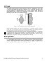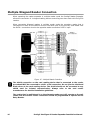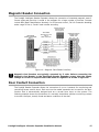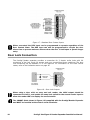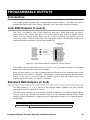
1
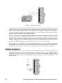
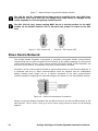
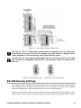
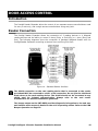
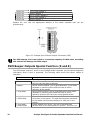
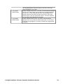
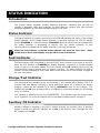
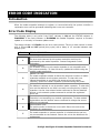
PRT-RDI2
Intelligent 2 Reader Expander
Installation Manual
CONTENTS
Protégé System .....................................................
Introduction
........................................................................................
Reader Expander
........................................................................................
Features
..................................................................................................
Reader Expander Specifications
....................................................................
Protégé System Management Suite
..........................................................
Protégé Modules
........................................................................................
Installation ..........................................................
Package Contents
........................................................................................
Location and Mounting
..............................................................................
Cabinet Tamper Switch
.............................................................................
Earth Ground Connection
.............................................................................
AC Power
..................................................................................................
Backup Battery
........................................................................................
Status Indicator Output
..............................................................................
Encrypted Module Network ..............................................................................
Slave Device Network
..............................................................................
RS-485 Biasing Configuration
......................................................................
Introduction
......................................................................................
Reader Connection .......................................................................................
Multiple Reader Connection ................................................................................
Magnetic Reader Connection
......................................................................
Door Contact Connection
.............................................................................
Electric Lock Connection
............................................................................
…………………………………………………..
Introduction
.........................................................................................
Zone Inputs
........................................................................................
Trouble Zone Inputs
...............................................................................
Programmable Outputs
…………………………………..
Introduction
.........................................................................................
Lock PGM Outputs (1 and 2)
.....................................................................
Standard PGM Outputs (3 to 8)
.....................................................................
Beeper Special Function
..............................................................................
Configuration Switch
3
3
3
3
4
5
7
7
7
8
8
9
10
10
11
12
14
.......................................... 15
Door Access Control
Zone Inputs
3
15
15
16
16
16
17
20
20
20
21
22
22
22
22
23
............................................. 25
Introduction
.........................................................................................
Address Configuration
...........................................................................
Protégé Intelligent 2 Reader Expander Installation Manual
25
25
1
Status Indication
.................................................. 26
Introduction
......................................................................................
Status Indicator
......................................................................................
Fault Indicator
......................................................................................
Charge/Test Indicator
............................................................................
Auxiliary OK Indicator
..............................................................................
AC OK Indicator
......................................................................................
5V Isolated Power Indicator
..................................................................
Lock 1/Lock 2 Indicators
............................................................................
Network RX/TX Indicator
............................................................................
Slave RX/TX Indicator
............................................................................
R1 and R2 Power Indicator ............................................................................
R1 and R2 Data Indicator
..............................................................................
Error Code Indication
..........................................
Introduction
.......................................................................................
Error Code Indication
............................................................................
Ordering Information
Product Codes
Warranty
Introduction
Contact
2
26
26
26
26
26
26
27
27
27
27
27
27
29
29
29
........................................... 30
......................................................................................
............................................................
......................................................................................
...............................................................................................
30
34
34
34
Protégé Intelligent 2 Reader Expander Installation Manual
PROTÉGÉ SYSTEM
Introduction
The Protégé System is a powerful integrated alarm and access control management system
designed to provide integration with building automation, apartment complex control and
HVAC in one flexible package. Communicating through a proprietary high speed protocol
across an encrypted RS-485 network using modular-based hardware design, system installers
have the flexibility to accommodate any installation from small or large, residential or
commercial.
Reader Expander
The PRT-RDI2 Protégé Reader Expander extends the number of card reader inputs on the
system by 2, number of zone inputs by 8 (4 zones used for door monitoring and control and
up to eight can be used for extended functionality) and the number of PGM outputs by 8
(includes 2 monitored lock control outputs).
Flexible module network architecture allows large numbers of modules to be connected to the
RS-485 Module Network. Up to 250 modules can be connected to the Protégé System in any
combination to the network up to a distance of 900M (3000ft). Communication beyond this
distance requires the use of a RS-485 Network Extender.
Locking a network prevents the removal, substitution or addition of modules to the module
network effectively preventing any tampering with the system.
Features
•
•
•
•
•
•
•
•
•
4 Wiegand Reader Mode for 2 Entry/Exit Doors Per Reader Expander
Secure Encrypted RS-485 Module Communications
8 Zone Inputs
2 Monitored Lock Control PGM Outputs
6 Open Collector PGM Outputs (Reader Control Outputs)
1.5A Switching Power Supply
Intelligent Battery Charge and Monitoring
Smart Reader Missing/Tamper Monitoring
Online and Remote upgradeable firmware
Reader Expander Specifications
The following specifications are important and vital to the correct operation of the
PRT-RDI2 Protégé Reader Expander. Failure to adhere to the specifications will
result in any warranty or guarantee that was provided becoming null and void.
Integrated Control Technology continually strives to increase the performance of its products
and as a result the specifications may change without notice. It is recommended that you
always consult www.integratedcontroltechnology.com for the latest documentation and
product information.
Protégé Intelligent 2 Reader Expander Installation Manual
3
Power Supply
AC Input Voltage
Operating Current
DC Output (Auxiliary)
Battery Charging
Battery Low
Battery Restore
16VAC 50/60Hz @ 40VA (Max)
280mA (Typical)
1.2A (Max)
350mA/700mA
10.5VDC
11.5VDC
Communication
RS-485
RS-485
Isolated Module Network
Isolated Slave Network
Outputs
Lock Outputs
PGM Outputs
Status Output
Inputs
Zone
Tamper
Trouble Zone
Dimensions
PCB Dimensions
Enclosure
Temperature
Operating
Humidity
Storage
2 Outputs
400mA (Max), 500mA Shutdown
6 (50mA Max) Open Collector
50mA (Max) Open Collector
8 (500ms to 40sec Input Speed)
1 (Normally Closed)
16
183mm X 234mm
7.2" X 9.2"
330mm X 406mm X 89mm
13" X 16" X 3.5"
5˚- 55˚ Celsius
41˚ - 131˚ Fahrenheit
0%-85% (Non-Condensing)
-10˚- 85˚ Celsius
14˚ - 185˚ Fahrenheit
It is important that the unit is installed in a dry cool location that is not affected by
humidity. Do not locate the unit in air conditioning or a boiler room that can exceed
the temperature or humidity specifications.
The isolated communications interface on the Protégé Reader Expander uses full
galvanic isolation to prevent ground loop noise and cross phase ground differential.
This is a very important feature of the product family and the correct connection of
power to this isolated section will ensure the correct operation of the
communications network. Failure to apply power to the communication interface
will prevent the operation of the communication interface.
Protégé System Management Suite
The Protégé System Management Suite is a Windows 2000/XP Professional Integrated Access
Control and Alarm Management system designed for any configuration from single site, single
4
Protégé Intelligent 2 Reader Expander Installation Manual
controller applications up to the global multi-national corporations using multiple site, multiple
controller installations.
The Protégé System Management Suite application is ideal for the configuration and
management of your Protégé installation. Special built in features and the quick-start kit will
get your system up and running in minutes.
Protégé Modules
The Protégé System can be expanded to accommodate large numbers of modules using the
encrypted RS-485 network. Modules that are currently available are listed below. Visit the
Integrated Control Technology website www.integratedcontroltechnology.com for the latest
Protégé module and product information.
Alphanumeric LCD User Interface (PRT-KLCD)
The Protégé LCD User Interface Keypad is the interface between the user and the
Protégé System. All programming and end user functions can be performed using the
LCD Keypad. The 32 character alphanumeric display uses easy to read messages and
menus to guide users through the systems operation. The LCD Keypad also adds two
zones (four zones in multiple zone configuration) and one PGM to the Protégé System.
16 Zone Expansion Module (PRT-ZX16)
Extends the Protégé System with the addition of 16 Zones and 4 Programmable
Outputs (PGM's). Operates from 16VAC with onboard power supply and isolated
communication interface.
16 Zone Standard Expansion Module (PRT-ZXS16)
Extends the Protégé System with the addition of 16 Zones and 1 Programmable
Output (PGM). Operates from 12VDC network connection. No onboard power supply.
16 PGM Expansion Module (PRT-PX16)
Extends the Protégé System with the addition of 16 Programmable Outputs (PGM's)
(16 7A FORM C Relays). The PRT-PX16 can be connected to the slave communications
interface of the PRT-RDI2 2 Reader Expansion Module for FULL monitored elevator
control with the addition of the PRT-DRI Destination Reporting Interface Optical Input
Module.
16 PGM Standard Expansion Module (PRT-PXS16)
Extends the Protégé System with the addition of 16 Programmable Outputs (PGM's)
(16 20mA Open Collector Outputs). Operates from 12VDC network connection. No
onboard power supply.
Ethernet Intelligent 2 Reader Expansion Module (PRT-RDE2)
Communicating over a high speed interface using 10/100 Ethernet, interface
connection for two card readers, either Wiegand or Magnetic Stripe formats. Four
Wiegand Card Readers can be connected in Multiple Card mode. The 2 Reader Ethernet
Expansion Module also adds 8 Zones and 8 Outputs to the Protégé System. Some of
the outputs on the PRT-RDE2 have specific access control functions and can be used as
zones in the Protégé alarm processing functions.
Protégé Intelligent 2 Reader Expander Installation Manual
5
Intelligent 2 Reader Expansion Module (PRT-RDI2)
Adds the interface connection for two card readers, either Wiegand or Magnetic Stripe
formats. Four Wiegand Card Readers can be connected in Multiple Card mode. The 2
Reader Expansion Modules also adds 8 Zones and 8 Outputs to the Protégé System.
Some of the outputs on the PRT-RDI2 have specific access control functions and can
be used as zones in the Protégé alarm processing functions.
Mini 2 Reader Expansion Module (PRT-RDM2)
Adds the interface connection for two card readers, either Wiegand or Magnetic Stripe
formats. Four Wiegand Card Readers can be connected in Multiple Card mode. The 2
Reader Expansion Modules also adds 6 Zones and 8 Outputs to the Protégé System.
Some of the outputs on the PRT-RDM2 have specific access control functions and can
be used as zones in the Protégé alarm processing functions.
Analog 4 Channel Input Expansion Module (PRT-ADC4)
Protégé allows the connection of the latest building automation technology and
completely integrated building automation solutions. Adds 4 Analog Inputs (4-20mA or
0-10V) allowing the connection of numerous industrial automation sensors. The Analog
Input Expansion Modules also adds 4 PGM Outputs to the Protégé System.
Analog 4 Channel Output Expansion Module (PRT-DAC4)
Protégé allows the connection of the latest building automation technology and
completely integrated building automation solutions. Adds 4 Analog Outputs (4-20mA
or 0-10V) allowing the connection of numerous industrial automation outputs including
air damper and sun louver controls as well as analog flow valves. The Analog Output
Expansion Modules also adds 4 PGM Outputs to the Protégé System.
6
Protégé Intelligent 2 Reader Expander Installation Manual
INSTALLATION
Package Contents
When receiving the PRT-RDI2 Protégé Reader Expander you should find the kit contains the
items listed below. The kit type is clearly labelled on the packaging and will tell you what your
kit contains. Please note that if you do not have the correct contents contact your distributor
immediately.
PRT-RDI2-PCB
Contents:
Protégé Reader Expander PCB Only
Reader Expander Printed Circuit Board
6 X Plastic Mounting Standoffs
20 X 1K Ohm Resistors
2 X 1N4007 Lock Reverse EMF Protection Diodes
Red/Black Backup Battery Wires
Location and Mounting
The Protégé Reader Expander is available as a PCB Only (Printed Circuit Board) or complete
unit supplied with a metal cabinet. It is recommended that the cabinet provided be used
where possible, as this provides the best mounting and installation solution as well as the
required cable entry and termination space.
When installing the Protégé Reader Expander ensure that there is adequate clearance around
all sides of the enclosure and air flow to the vents of the enclosure are not restricted.
It is recommended to install the Protégé Reader Expander in a location that will facilitate easy
access for wiring. It is also recommended that the Protégé Reader Expander is installed in
electrical rooms, communication equipment rooms, closets or in an accessible area of the
ceiling.
1. Insert the plastic stand-offs in to the locations to mount the PCB board.
2. Calculate the location and position of the enclosure and mark the holes for the keyhole
points in the top left and right locations. This will allow you to screw in the screws and
then hang the box on them adjusting the location to suit.
3. Ensure a solid fixing point and screw in the two screws. Before tightening the top
screws insert the tamper bracket in the slot provided on the right side of the
enclosure.
4. Fix the enclosure securely using the remaining mounting holes on the bottom left,
right and centre of the enclosure.
5. Insert the PCB in to the enclosure and mount using the plastic standoffs inserted
during step one.
Install the enclosure when the circuit board is NOT installed on the plastic standoffs. This will reduce the risk of damage caused by debris during the installation
process.
Protégé Intelligent 2 Reader Expander Installation Manual
7
Cabinet Tamper Switch
The enclosure tamper input signals to the monitoring station or remote computer that the
reader expander enclosure has been opened. The tamper input switch should be mounted into
the steel bracket provided and connected to the tamper connection terminals as shown in the
diagram below. The tamper input opens and closes trouble zone RDxxx:01 on the reader
expander.
Figure 1 - Tamper Input
Earth Ground Connection
The Protégé Reader Expander has a connection for earth ground. For best results a cold water
pipe should be used with a pipe wiring clamp. If a cold water pipe is not available connect to a
suitable ground connection in the installation.
A minimum 14AWG solid copper wire should be used from the Protégé Reader Expander's
earth connection point to the clamp on the cold water pipe. If other earth clamps are present
at the same connection point connect the clamp below the existing units.
Figure 2 - Reader Expander Main Earth Ground Connections
8
Protégé Intelligent 2 Reader Expander Installation Manual
AC Power
The Protégé Reader Expander should be supplied by a dedicated electrical power source rated
for a minimum 10Amp Load and have a dedicated circuit breaker. Do not use a switch
controlled breaker or a switched electrical point to supply electrical power. Connect the
primary of a 16.5VAC, 50/60Hz, 40VA Transformer to the electrical circuit and run the
secondary to the AC input on the controller terminals.
Figure 3 - AC Transformer 16VAC, 50/60Hz, 40VA MAX
Specific regional regulations may allow the transformer to be mounted inside the enclosure.
In this case wire the electrical circuit to the electrical termination point inside the enclosure
and the secondary wires of the transformer to the AC Input on the controller.
Termination of wiring to the reader expander while power is applied or the battery
is connected may cause serious damage to the reader expander and will VOID ALL
WARRANTEES OR GUARANTEES. Power the reader expander ONLY after all wiring,
configuration and jumper settings are completed and verified.
Backup Battery
It is recommended that a minimum of a 4Ah battery is used as the main backup battery.
From the accessory bag provided, connect the RED and BLACK battery termination wires to
the B+ and B- terminals. Connect the spade terminals to the battery as shown below.
Connection of the battery in reverse will not damage the Reader Expander but will cause the
battery fuse (5A Fast Blow) to blow and require replacement.
Protégé Intelligent 2 Reader Expander Installation Manual
9
Figure 4 - Battery Connection
The battery test procedure uses a special algorithm to prevent deep discharge and increase
battery endurance. A dynamic battery test is performed every ten minutes when AC power is
present and a battery condition alarm will be generated if the battery is either disconnected or
shows poor capacity. Battery fault conditions will activate the battery trouble zone associated
with the address assigned to the reader expander.
If AC is not present the Protégé Reader Expander will monitor the battery for a low voltage
level and will activate the battery trouble zone. The next dynamic battery test will occur 30
minutes after AC power has been restored. This delay allows the battery to achieve optimal
charging during the first 30 minutes when power is initially restored to the unit. Once the first
test is completed the dynamic battery testing will return to 10 minute intervals.
When power is first applied to the Protégé Reader Expander a dynamic battery test will be
performed after 30 seconds, this allows the status and condition of the battery to be detected.
On completion of this first test the normal testing period of 10 minutes will be resumed.
Status Indicator
The status output will activate according to the status indicator on the Protégé Reader
Expander and can be used to provide signalling or indication of the reader expander status
outside the enclosure. The following diagrams show the connection of an LED indicator to the
status output.
10
Protégé Intelligent 2 Reader Expander Installation Manual
Figure 5 - External Status LED Connection
Encrypted Module Network
The Protégé Reader Expander incorporates encrypted RS-485 communications technology.
The isolated communications interface offers full galvanic isolation to prevent ground loop
noise and cross phase ground differential between network devices.
Figure 6 - Standard Communications Connection
Connection of the communications should be performed according to the diagram shown in
figure 6. It is important that the N+ Network Communications Power be supplied from an
independent battery backed power supply unit or a networked module capable of supplying
the required voltage to all devices on the RS485 network.
Always connect the Reader Expanders NA and NB terminals to the NA and NB terminals of the
communication network. The N+ and N- must go to a 12V power supply source as shown in
the following diagram and connected at ONLY one +12V power source.
Protégé Intelligent 2 Reader Expander Installation Manual
11
Figure 7 - Network Power Supplied By Network Module
The 12V N+ and N- Communication input must be supplied from only ONE point.
Connections from more than one 12V supply may cause failure or damage to the
reader expander or device supplying network power.
The EOL (End Of Line) jumper setting MUST be set in the ON position for the LAST
module on the RS485 network. EOL is ON when the jumper is closest to the EOL
text.
Figure 8 - EOL Jumper ON
Figure 9 - EOL Jumper OFF
Slave Device Network
The Protégé Reader Expander incorporates a secondary encrypted RS-485 communication
interface that can be used to expand the functionality of the reader expander for the purpose
of High Rise Elevator Control. A floor control module PRT-PX16 Protégé 16 PGM Expander, set
as a floor control device, is attached to the slave communication interface.
Connection of the communications should be performed according to the following diagram. It
is important that the S+ Slave Communications Power be supplied from an independent
battery backed power supply unit or a module connected to the slave communication
interface capable of supplying the required voltage to all devices on the slave RS485 network.
Figure 10 - Slave Communications Connection
Always connect the Reader Expanders SA and SB terminals to the SA and SB terminals of the
slave devices. The S+ and S- must go to a 12V power supply source as shown in the following
diagram.
12
Protégé Intelligent 2 Reader Expander Installation Manual
Figure 11 - Slave Power Supplied By Module
The 12V S+ and S- Communication input must be supplied from only ONE point.
Connections from more than one 12V supply may cause failure or damage to the
reader expander or device supplying salve communication power.
The EOL (End Of Line) jumper setting MUST be set in the ON position for the LAST
slave module on the RS485 network. EOL is ON when the jumper is closest to the
EOL text.
Figure 12 - EOL Jumper ON
Figure 13 - EOL Jumper OFF
RS-485 Biasing Settings
The Protégé Reader Expander has biasing settings for the network and slave communication
ports. Biasing can be configured for either high or low (L indicates a low bias and H indicates
high bias configuration). Both jumpers MUST be set to the same bias type.
When the slave communications is being used to communicate with PRT-PX16 devices in floor
control mode or being used to repeat the network communications the biasing MUST be set to
Protégé Intelligent 2 Reader Expander Installation Manual
13
low if this is the first RS-485 connection. The other devices must be set to no biasing (Jumper
removed or in the middle).
Biasing should only be set to LOW on ONE point on any single segment of the RS485 network. All other devices on the same segment should be set to the middle
position which is no biasing.
The PRT-CTRL System Controller by default has the jumpers for the biasing set to
low and the EOL jumper on. This is also the same default configuration for the slave
communication port on the Protégé Intelligent Reader Expander.
14
Protégé Intelligent 2 Reader Expander Installation Manual
DOOR ACCESS CONTROL
Introduction
The Protégé Reader Expander allows the control of two separate access controlled doors used
for entry or exit only, and a single access controlled door using entry/exit.
Reader Connection
The Protégé Reader Expander allows the connection of 2 reading devices or 4 Wiegand
reading devices and the ability to control 2 doors (Entry or Exit Only) or 1 door (Entry and
Exit). The following diagrams show the connection of standard Wiegand Reader with the
Protégé Reader Expander controlling an Access Door and Entry/Exit Door.
Figure 14 - Standard Reader Interface
The shield connection on the card reading device that is connected to the reader
port should NOT be connected to a AUX- or 0V connection. Do not join the shield and
black wires at the card reading device. The shield should not be connected to any
shield used for isolated communication. Always refer to the card reader
manufacturer for detailed installation guidelines.
The beeper output on the PRT-RDI2 provides diagnostic information to the end user
and installer when access is denied or the unit is operating offline. Refer to the PGM
Beeper Operation on Page 22.
Protégé Intelligent 2 Reader Expander Installation Manual
15
Multiple Wiegand Reader Connection
When operating the reader expander in multiple reader mode the Protégé Reader Expander
allows the connection of 4 wiegand reading devices controlling two doors each with Entry/Exit
readers.
When connecting Wiegand readers in multiple reader mode the secondary reader that is
connected will have all connections wired to the same port as the primary card reader with
the DATA 1 connection wired to the opposite reader connection DATA 1 input.
Figure 15 - Multiple Reader Interface
The shield connection on the card reading device that is connected to the reader
port should NOT be connected to a AUX- or 0V connection. Do not join the shield and
black wires at the card reading device. The shield should not be connected to any
shield used for isolated communication. Always refer to the card reader
manufacturer for detailed installation guidelines.
The reader that is multiplexed in to the alternate reader port will operate as the exit
reader and the normal reader connection should be programmed to operate as the
Entry Reader.
16
Protégé Intelligent 2 Reader Expander Installation Manual
Magnetic Reader Connection
The Protégé Intelligent Reader Expander allows the connection of standard magnetic track 2
format cards and provision is made in the software for a large number of formats. Formats
include BIN (Bank Identification Number) for ATM access control, Full 16 Character decoding
and a range of first 4, 5 and 6 card number encoding.
Figure 16 - Magnetic Card Reader Interface
Magnetic Card Readers are typically operated by 5 volts. Before connecting the
Magnetic Card Reader to the Intelligent Reader Expander ensure that the supply
voltage is correct. If required insert the inline 5V regulator as shown in figure 16.
Door Contact Connection
The Protégé Reader Expander allows the connection of up to 4 contacts for monitoring and
controlling access control doors. Each zone on the reader expander can be used for the door
function that is automatically assigned and as a normal zone input on the system. The
following example shows the connection of a normally closed door position monitoring contact
to monitor the open, closed, forced and alarm conditions of the door.
Protégé Intelligent 2 Reader Expander Installation Manual
17
Figure 17 - Standard Door Contact Inputs
When connected the REX input can be programmed to operate regardless of the
Door Contact State. The REX input can also be programmed to recycle the door
alarm time to prevent nuisance alarms when the door is held open to permit longer
entry.
Door Lock Connection
The Protégé Reader expander provides a connection for 2 electric strike locks with full
monitoring of the lock circuit for tamper and over current/fuse blown conditions. The door
lock monitoring can be disabled if it is not required. For information on the LOCK control
status, refer to the Indication section on page 26.
Figure 18 - Door Lock Outputs
When using a door with an entry and exit reader, the LOCK output should be
connected to LOCK 1, and enable the swap lock option for the second reader input to
allow the reader LED's to display the correct status.
The 1N4007 diode shown in Figure 16 is supplied with the Protégé Reader Expander
and MUST be installed at the electric strike terminals.
18
Protégé Intelligent 2 Reader Expander Installation Manual
ZONE INPUTS
Introduction
The Protégé Reader Expander has 8 Zone Inputs. The reader expander also monitors 16
trouble zones used to report trouble conditions. A trouble zone is in most cases not physically
connected with a device, rather it is related within the system. For example a module
communication fault causes a trouble zone to open as a result of the communication failure.
Zone Inputs
The Protégé Reader Expander can monitor the state of up to 8 zone inputs such as magnetic
contacts, motion detectors and temperature sensors. Devices connected to these zones can
be installed to a maximum distance of 300m (1000ft) from the Controller when using 22
AWG. The Controller supports normally opened and normally closed configurations with or
without EOL resistors on a per zone configuration setting.
Zones can be programmed from the Protégé LCD Keypad (PRT-KLCD) or using the Protégé
System Management Suite (PRT-SMGT). RD001:01 to RD001:08 represent Zone 1 to Zone 8
on the Protégé Reader Expander (Substitute the module address for the appropriate address
being programmed).
When using a zone with the EOL resistor configuration, the controller generates an alarm
condition when the state of a zone changes and generates a tamper alarm condition when a
wire fault (short circuit) or a cut wire (tampered) in the line occurs.
When using the EOL resistor configuration, the EOL resistor option must be turned on for the
zone(s) so that the tamper and short states can be monitored (refer to Zones Section in the
Protégé Reference Manual).
Figure 19 - EOL Resistor Zone Configuration
Each zone input can use a different input configuration. To program a large number of zones,
with a single configuration type, use the Multiple Selection feature in the Protégé System
Management Suite application.
Protégé Intelligent 2 Reader Expander Installation Manual
19
When using the No Resistor configuration, the Controller only monitors the opened and closed
state of the connected input device generating the (OPEN) Alarm and (CLOSED) Sealed
conditions.
Figure 20 - Normally Closed Zone Configuration No Resistors
Trouble Zone Inputs
Each reader expander can monitor up to 16 trouble zones. Trouble zones are used to monitor
the status of the reader expander and in most cases are not physically connected to an
external zone. For example, trouble zone RD001:06 is used to monitor door 1 for a forced
open condition and will generate an alarm state if the door is forced.
The following table details the trouble zones that are configured in the system and the trouble
type and group that they activate.
Zone Number
Description
Type
Group
RDxxx:01
RDxxx:02
RDxxx:03
RDxxx:04
RDxxx:05
RDxxx:06
RDxxx:07
RDxxx:08
RDxxx:09
RDxxx:10
RDxxx:11
RDxxx:12
RDxxx:13
RDxxx:14
RDxxx:15
RDxxx:16
Module Tamper
AC failure
Low Battery
Aux Failure
Lock Failure
Door 1 Forced
Door 2 Forced
Door 1 Left Open
Door 2 Left Open
Reader 1 Voltage
Reader 2 Voltage
Reader 1 Tamper
Reader 2 Tamper
Door 1 Lockout
Door 2 Lockout
Module Offline
System Tamper
Power Fault
Power Fault
Power Fault
Power Fault
Forced Door
Forced Door
Left Open
Left Open
Power Fault
Power Fault
System Tamper
System Tamper
Attempts
Attempts
Module Offline
System
General
General
General
General
Access
Access
Access
Access
General
General
System
System
Access
Access
System
Replace the 'xxx' with the appropriate address of the reader expander that you are
programming.
20
Protégé Intelligent 2 Reader Expander Installation Manual
PROGRAMMABLE OUTPUTS
Introduction
The Protégé Reader Expander has 4 Programmable Outputs (PGM's). The PGM's are used to
activate the Electric Door Locks, Sirens, Lighting Control and Relay Accessory Products.
Lock PGM Outputs (1 and 2)
The + and - terminals of Lock1 (PGM1 RD001:01) and Lock2 (PGM2 RD001:02) are used to
power electric door strikes and other lock control devices that require a steady voltage
output. The lock outputs supply 12Vdc upon an unlock or activation and support up to 1A
inrush and 400mA continuous operation. The lock output uses an electronically fused circuit
and automatically shuts down if the current exceeds 1A.
Figure 21- Lock Output PGM1/2 Connection (PGM 1 Shown)
If the load on the lock terminals returns to normal (≤1A), the reader expander will reinstate
power to the lock terminals if they are activated.
When the lock output is not used, the appropriate trouble zone will be activated (refer to the
Trouble Zone Input section on Page 20). To avoid this, connect a 1kΩ resistor across the lock
output. If the Lock is not being used for another function, and the trouble zone is not
programmed in the system, no resistor is required.
Standard PGM Outputs (3 To 8)
The PGM outputs 3, 4, 5, 6, 7 and 8 on the Protégé Reader Expander are open collector
outputs and switch to a ground connection.
The PGM's have a default pre-programmed function as detailed in the following table and are
used to control the indicator and audible outputs on the attached reading device. These
functions may be disabled by programming the appropriate setting in the reader expander
configuration.
PGM Number
Description
RDxxx:03
LED 1 (Green) Reader 1
Protégé Intelligent 2 Reader Expander Installation Manual
21
RDxxx:04
RDxxx:05
RDxxx:06
RDxxx:07
RDxxx:08
LED 2 (Red) Reader 1
BEEPER Reader 1
LED 1 (Green) Reader 2
LED 2 (Red) Reader 2
BEEPER Reader 2
Replace the 'xxx' with the appropriate address of the reader expander that you are
programming.
Figure 22- Example Open Collector Output Connection (LED)
The PGM outputs 3 to 8 can switch to a maximum capacity of 50mA each, exceeding
this amount will damage the PGM output.
PGM Beeper Outputs Special Function (5 and 8)
The PGM beeper outputs 5 and 8 on the Protégé Reader Expander provide special diagnostic
information when a card is presented. The following table shows the beeper modes of
operation.
Function
Description
2 Beeps
Access Granted. The lock will activate and allow access to the
door the card has been presented.
Offline Access Granted. This is generated ONLY if the reader
expander is operating offline and the mode of offline
operation allows access.
Offline Access Denied. This is generated ONLY if the reader
expander is operating offline and the mode of offline
operation prevents this card from being allowed access.
Access Denied Card Number Not Known. The card number is
not known in the system. The card that has been presented
to the reader could not be matched to a valid user in the
system.
Access Denied Door Group. The user is denied access
because they do not have access to the door. This error will
4 Beeps
1 Long Beep
1 Long Beep
1 Short Beep
1 Long Beep
2 Short Beeps
22
Protégé Intelligent 2 Reader Expander Installation Manual
1 Long Beep
3 Short Beeps
1 Long Beep
4 Short Beeps
also be generated if the door group is not set or the door
group schedule is not valid.
Access Denied Area Group. The user is denied access because
they do not have access to the area that is being controlled
by the door. If the area that the door is associated with is
armed, and the user does not have this area in their area
disarm group, they will be denied access. This also depends
on the area group settings for the door.
Access Denied Access Level. The user is denied access
because they do not have a valid access level or the access
level they are assigned is currently outside the programmed
schedule.
Protégé Intelligent 2 Reader Expander Installation Manual
23
CONFIGURATION SWITCH
Introduction
The addressing of the Protégé Reader Expander allows up to 128 devices to be connected to
the Protégé System Controller. The 'CONFIG' configuration DIP switch allows each reader
expander to have a unique address.
Address Configuration
The switch positions 1 to 7 select the device address from 1 to 128. When setting an address
the reader expander must be powered down (Battery and AC) and restarted for the new
address to take affect. When changing the address the reader expander will automatically
default the internal configuration and require a network update. See the Protégé System
reference manual for information on performing a module update.
Figure 23- Reader Expander CONFIG Switch Functions
The device address is determined by adding the value of each switch that is selected in the
ON position and then adding 1 to this value. In the example below the address 079 results in
(64+8+4+2) + 1 = 079. Setting all address switches to OFF results in the default address of
001.
Figure 24- Reader Expander Configured For Address 079
24
Protégé Intelligent 2 Reader Expander Installation Manual
STATUS INDICATION
Introduction
The Protégé Reader Expander includes extensive diagnostic indicators that can aid the
installer in diagnostic faults and conditions. In some cases an indicator may have multiple
meanings depending on the status indicator display at the time.
Status Indicator
The Status Indicator is located in the centre of the PCB and indicates the status of the Protégé
reader expander. If the Protégé Reader Expander is operating normally the LED will indicate
this by FLASHING at 1 second intervals. FLASHING rapidly at 250ms intervals indicates that
the reader expander is attempting to register with the system controller, or that
communication has failed and the reader expander is retrying the request.
When the fault indicator is ON the status indicator will show an error code.
to the section Error Code Display on page 28 for more information.
Refer
Fault Indicator
The fault indicator LED is identified by the text 'FAULT' and is located in the centre of the PCB.
When the fault indicator is FLASHING the Reader Expander is operating in firmware update
mode, or there is no firmware loaded. The fault indicator when ON indicates that an error has
occurred while trying to register with the system controller. The status indicator will flash a
number of times indicating an error code. Refer to the section Error Code Display on page 28
for more information.
Charge/Test Indicator
The charge and test indicator serves two functions; it will indicate that a Battery Test is in
progress and that Battery Charging is being performed. When AC is present the battery
charging current will be indicated by a varying INTENSITY level on this indicator. This
indicator will be ON when a battery test is in progress by illuminating brightly for 30 seconds
every 10 minutes.
This indicator is identified by the text 'CHARGE/TEST'. This indicator does not function when
no AC is present. For more information refer to the Battery Backup section on page 9.
Auxiliary OK Indicator
Auxiliary voltage is supplied to the AUX+ outputs through the auxiliary fuse. If auxiliary
supply is normal the 'AUX OK' indicator will be ON. If the auxiliary fuse is damage the 'AUX
OK' indicator will be OFF.
Protégé Intelligent 2 Reader Expander Installation Manual
25
AC OK Indicator
When a valid AC input is provided to the Protégé System Controller the 'AC OK' indicator will
be ON. When the AC is disconnected or has failed the 'AC OK' indicator is OFF.
5V Isolated Power Indicator
The reader expander communicates using an isolated RS-485 interface for optimal
performance and this requires an isolated supply on the N+ and N- or the S+ and Sterminals. When a valid power supply is input the '5V ISO' indicator will be ON for the
interface. The '5V ISO' indication is shown on the slave and network isolated interfaces.
Lock 1/Lock 2 Indicators
The Lock 1 and Lock 2 indicators will show the status of the Lock Output and the over current
or circuit fault conditions.
ON
TWO FLASHES
Lock is ON.
Lock is ON, the circuit is in Over Current
Protection or the fuse has blown.
Lock is OFF, the circuit to the locking device
is cut, damaged or tampered.
THREE FLASHES
Network RX/TX Indicator
The Network Receive and Transmit Data indicators are located on the top right side of the
PCB beside the network communication interface. The indicator shows when the Protégé
Reader Expander is transmitting and receiving information from the module communications
interface and is identified by the text 'RX' and 'TX'. When the indicator is ON data is being
transmitted or received.
Slave RX/TX Indicator
The Slave Receive and Transmit Data indicators are located on the right side of the PCB
beside the slave communication interface. The indicator shows when the Protégé Reader
Expander is transmitting and receiving information from the slave communications interface
and is identified by the text 'RX' and 'TX'. When the indicator is ON data is being transmitted
or received.
R1 and R2 Power Indicator
The R1 and R2 power indicators are located beside the reader 1 and reader 2 connection
terminals. Reader voltage is supplied to the R+ outputs through the reader fuse. If the reader
supply is normal the indicator will be ON. If the indicator is OFF the reader fuse is damaged.
26
Protégé Intelligent 2 Reader Expander Installation Manual
R1 and R2 Data Indicator
The R1 and R2 data indicators are located beside the reader 1 and reader 2 connection
terminals. A short FLASH (<250 Milliseconds) on the Data Indicator will show that data was
received but was not in the correct format. A long FLASH (>1 Second) indicates that the unit
has read the data and the format was correct.
Protégé Intelligent 2 Reader Expander Installation Manual
27
ERROR CODE INDICATION
Introduction
When the reader expander attempts to register or communicate with the system controller a
registration error can be generated indicating that it was not successful.
Error Code Display
The following table is only valid if the FAULT indicator is ON and the STATUS indicator is
FLASHING. If the fault indicator is FLASHING the Reader Expander requires a firmware
update or is currently in firmware update mode.
The status indicator will FLASH with the error code number. The error code number is shown
with a 250ms ON and OFF period (duty cycle) with a delay of 1.5 seconds between each
display cycle.
FLASH
1
2
3
4
5
6
7
28
ERROR DESCRIPTION
Unknown Error Code
The error code returned by the system controller could not be
understood by the reader expander. Contact Integrated Control
Technology..
Firmware Version
The firmware version on the reader expander is not compatible with
the system controller. To clear this error, update the module using the
module update application.
Address Too High
The reader expander address is above the maximum number of reader
expanders available on the system controller. To clear this error
change the address to one within the range set on the system
controller, restart the reader expander by disconnecting the power.
Address In Use
The Address is already in use by another reader expander. To clear this
error set the address to one that is currently not occupied by a reader
expander. Use the view network status command to list the attached
devices, or the network update command to refresh the registered
device list.
Controller Secured Registration Not Allowed
Controller is not accepting any module registrations. To allow module
registrations use the network secure command to change the secure
setting to not secured.
Serial Number Fault
The serial number in the device is not valid. Return the unit to the
distributor for replacement.
Locked Device
The reader expander or system controller is a locked device and can
not communicate on the network. Return the unit to the distributor for
replacement.
Protégé Intelligent 2 Reader Expander Installation Manual
ORDERING INFORMATION
Product Codes
Please use the following product codes when placing an order for the Protégé Reader
Expander.
PRT-RDI2-PCB
Protégé Reader Expander (PCB Only)
Includes
Accessory Bag
To order the Protégé Intelligent Reader Expander in a cabinet order the CAB-LRG large steel
cabinet complete with transformer and tamper connections.
Manuals and literature are available at the Integrated Control Technology website in the
documentation section. If you require manuals on CD-ROM please request a literature CDROM from the website.
Protégé Intelligent 2 Reader Expander Installation Manual
29
WARRANTY
Introduction
The Protégé Reader Expander is covered under the Integrated Control Technology standard
terms and warranty agreement. This document can be downloaded from the Integrated
Control Technology web site or obtained by return fax.
Contact
Integrated Control Technology welcomes all feedback. Please visit our website or use the
information below.
Integrated Control Technology
P.O. Box 302-340
North Harbour Post Centre
Auckland
New Zealand
Phone:
Fax:
Unit C,
6 Ascension Place
Mairangi Bay
Auckland
New Zealand
+64-9-476-7124
+64-9-476-7128
www.integratedcontroltechnology.com
30
Protégé Intelligent 2 Reader Expander Installation Manual
NOTES
________________________________________________________________________________
________________________________________________________________________________
________________________________________________________________________________
________________________________________________________________________________
________________________________________________________________________________
________________________________________________________________________________
________________________________________________________________________________
________________________________________________________________________________
________________________________________________________________________________
________________________________________________________________________________
________________________________________________________________________________
________________________________________________________________________________
________________________________________________________________________________
________________________________________________________________________________
________________________________________________________________________________
________________________________________________________________________________
________________________________________________________________________________
________________________________________________________________________________
________________________________________________________________________________
________________________________________________________________________________
________________________________________________________________________________
________________________________________________________________________________
________________________________________________________________________________
________________________________________________________________________________
________________________________________________________________________________
Protégé Intelligent 2 Reader Expander Installation Manual
31
NOTES
________________________________________________________________________________
________________________________________________________________________________
________________________________________________________________________________
________________________________________________________________________________
________________________________________________________________________________
________________________________________________________________________________
________________________________________________________________________________
________________________________________________________________________________
________________________________________________________________________________
________________________________________________________________________________
________________________________________________________________________________
________________________________________________________________________________
________________________________________________________________________________
________________________________________________________________________________
________________________________________________________________________________
________________________________________________________________________________
________________________________________________________________________________
________________________________________________________________________________
________________________________________________________________________________
________________________________________________________________________________
________________________________________________________________________________
________________________________________________________________________________
________________________________________________________________________________
________________________________________________________________________________
________________________________________________________________________________
32
Protégé Intelligent 2 Reader Expander Installation Manual
Unit C, 6 Ascension Place, Mairangi Bay, P.O. Box 302-340
North Harbour, Auckland, New Zealand.
Phone: +64 (9) 476 7124 y Fax: +64 (9) 476 7128
www.integratedcontroltechnology.com