1
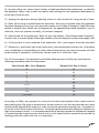
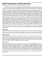
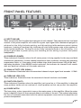
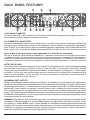
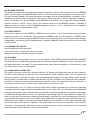
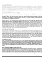
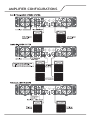
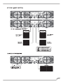
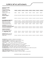
PROFESSIONAL POWER AMPLIFIER
PTA3000
OPERATING GUIDE
SAFETY INSTRUCTIONS
Intended to alert the user to the presence of uninsulated “dangerous voltage”
within the product’s enclosure that may be sufficient magnitude to constitute
a risk of electric shock to persons.
Intended to alert the user of the presence of important operating and
maintenance (servicing) instructions in the literature accompanying the product.
CAUTION: Risk of electrical shock DO NOT OPEN!
CAUTION: To reduce the risk of electric shock, do not remove cover. No user serviceable
parts inside. Refer servicing to qualified service personnel.
WARNING: To prevent electrical shock or fire hazard, this apparatus should not be exposed
to rain or moisture, and objects filled with liquid, such as vases, should not be placed on this
apparatus. Before usin g this apparatus, read the operating guide for further warnings.
IMPORTANT SAFETY INSTRUCTIONS.
When using electrical products, caution should always be used. Please read
and keep these safety instructions.
1. Read these instructions.
2. Keep these instructions.
3. Heed all warnings.
4. Follow all instructions.
5. Do not use this apparatus near water.
6. Clean only with a dry cloth.
7. Do not block any of the ventilation openings. Install in accordance with manufacture’s
instructions.
8. Do not install near any heat sources such as a radiator, heat register, stove or other
apparatus (including amplifiers) that produce heat.
9. Do not defeat the safety purpose of the polarized or grounding-type plug. A polarized plug has
two blades with one wider than the other. A grounding type plug has two blades with a third
grounding plug. The wide blade or thirds prong is provided for your safety. If the provided plug
does not fit into your outlet, consult an electrician for replacement of the obsolete outlet.
10. Protect the power cord from being walked on or pinched, particularly at plugs, convenience
receptacles, and the point they exit from the apparatus.
11. Only use attachments/accessories provided by the manufacture.
12. Use only with a cart, stand, tripod, bracket, or table specified by the manufacture, or sold with
the apparatus. When a cart is used, use caution when moving the cart/apparatus combination to
avoid injury from tip-over.
13. Unplug this apparatus during lightning storms or when unused for long periods of time.
14. Refer all servicing to qualified service personnel. Servicing is required when the apparatus
has been damaged in any way, such as power-supply cord or plug is damaged, liquid has been
spilled or objects have fallen into the apparatus, the apparatus has been exposed to rain or
moisture, does not operate normally, or has been dropped.
15. Never break off the ground pin. Write for our free booklet “Shock Hazard and Grounding”.
Connect only to a power supply of the type marked on the unit adjacent to the power supply cord.
16. If this product is to be mounted in an equipment rack, rear support should be provided.
17. Exposure to extremely high noise levels may cause permanent hearing loss. Individuals
vary considerably in susceptibility to noise-induced hearing loss, but nearly everyone will lose
some hearing if exposed to sufficiently intense noise for a sufficient time.
The US Government’s Occupational and Health Administration (OSHA) has specified the
following permissible noise level exposures:
Sound Level dBA, Slow Response
Duration Per Day In Hours
8
90
6
92
4
95
3
97
2
100
1 1/2
102
1
105
1/2
110
1/4 or less
115
According to OSHA, any exposure in excess of the above permissible limits could result in
some hearing loss. Ear plugs or protectors to the ear canals or over the ears must be worn when
operating this amplification system in order to prevent permanent hearing loss, if exposure is
in excess of the limits as set forth above. To ensure against potentially dangerous exposure to
high sound pressure levels, it is recommended that all persons exposed to equipment capable
of producing high sound pressure levels such as this amplification system be protected by
hearing protectors while this unit is in operation.
2
SERIES PROFESSIONAL POWER AMPLIFIER
Thanks for choose our series amplifier. The amplifier features a two-way crossover and
sub-sonic (low-cut) filter for each channel. Crossover frequencies are fixed at 150 Hz, allowing
subwoofers to be driven at extremely high sound pressure levels, and the filters cut at 40 Hz to
prevent low-end rumble. Using proven technology gained through years of amplifier design, this
unit takes advantage of rugged TO-3P output devices mounted on massive aluminum extrusions
and dissipates heat via an extremely quiet and effective two-speed fan. The amplifiers employ
mammoth toroidal power transformers and offer impressive specifications and features not found
on similarly priced competitive units. This amp is designed to drive a 2-Ohm load per channel,
thus achieving awesome performance levels into 4 Ohms in BRIDGE mode. The amplifiers are
ruggedly constructed, rack-mountable pieces of gear with superb patching capability, allowing
superior flexibility in application. Front panel features include calibrated, detented gain (dB)
controls and LED indicators for power, signal presence (SIG), clip and fault, as well as a rocker
mains POWER switch. The back panel contains an IEC connector for the mains power cord,
a mains circuit breaker with reset, and 2 critical cooling fan opening. This opening should have an
adequate supply of cool air and should never be blocked or restricted. Also on the back panel are
the input and output sections, including an input barrier strip for permanent installation. Each
channel inputs section includes a combo XLR/ 1/4"phone jack connector. THRU/LOW out and
HIGH out 1/4" jacks, and activation switches for the LOW CUT filter and crossover
(150Hz X OVER). Channel output sections feature dual shock-proof binding posts and four
conductor Speakon connectors. An additional four-conductor Speakon connector allows BRIDGE
mode output.
UNPACKING
Inspect the amplifier during unpacking. If any damage is found, notify your dealer immediately.
Be sure to save the carton and all packing materials. Should you ever need to ship the unit back
to Sixstar DJ, one of its service centers, or the dealer: use only the original factory packing.
INSTALLATION
The professional power amplifiers are design for durability in commercial installations and
provide the quality performance required in studio and home applications. They are two-rackspace units of 16" (406mm) depth designed to mount in a standard 19" rack. Rear mounting
ears are provided for additional support. The minimum rack depth required from the mounting
surface is 17" (432mm) to allow adequate connector clearance.
BASIC SETUP
Rack mount the amplifier in the location where it is to be used, remembering to allow for
adequate access and cooling space. Make all the connections to the proper INPUT connectors
on the desired channel. Select the proper mode configuration (STEREO or BRIDGE). Connect
speakers to the proper OUTPUT connectors, reviewing carefully the impedance and phase
considerations. With the POWER switch OFF, connect the IEC cord (7) to the amplifier and then
to a suitable electrical outlet to allow proper current draw. With both channel gain (dB) controls
at their fully counterclockwise settings, turn the POWER switch to ON, and slowly raise the gain
controls to desired settings. Please carefully review this manual. It covers all this information in
greater detail.
FRONT PANEL FEATURES
(1) INPUT GAIN (dB)
These controls are used to adjust the input gain of each channel. They determine how loud each
channel of the power amplifier will sound for a given input signal level. Maximum input gain is
achieved at the fully clockwise setting, and this setting yields maximum mixer/system
headroom. A setting of less than fully clockwise will yield lower system noise at the expense of
mixer/system headroom. Turning the control fully counterclockwise is the off setting . It is
always a good idea to power up any new installing at this setting to protect the system
loudspeakers.
(2) POWER LED (POWER)
These indicators illuminate when the AC mains power is being supplied to the amp and both
channels are operational. If either channel experiences fault conditions, exceeds safe operating
temperature limits, or if the mains circuit breaker trips; both channel power LED will be dark,
indicating shutdown. If the BRIDGE mode is selected, the indicator on channel B will remain
dark as a positive indication of this mode selection.
(3) SIGNAL ACTIVITY LEDS (SIGNAL)
These indicators illuminate when the associated channel output signal level exceeds 1 V RMS.
(4) OVERLOAD LEDS (CLIP)
These indicators illuminate when the associated channel has been overloaded.
(5) FAULT LEDS (FAULT)
These indicators illuminate when the amplifier just turned on or if the amplifier is detected
some problem inside such as overheat or circuit problem so that can protect the amplifier.
(6) POWER SWITCH
This heavy-duty, rocker-type switch turns on the mains power to the amplifier. When the mains
power is applied, there is a three-second delay in activation of the unit. This reduces/eliminates
the turn-on transients associated with the system equipment connected to the amplifier and
protects loudspeakers.
4
BACK PANEL FEATURES
(7) IEC MAINS CONNECTOR
This is a standard IEC power connector. An AC mains cord having the appropriate AC plug and ratings for
the intended operating voltage is included in the carton.
U.S. DOMESTIC AC MAINS CORD
The mains cord supplied with the unit is a heavy-duty, 3-conductor type with a conventional 120 VAC plug
with ground pin. It should be connected to an independent circuit capable of continuously supporting at
least 15 amps. This is particularly critical for sustained high-power applications. If the outlet used does not
have a ground pin, a suitable grounding adapter should be used and the third wire grounded properly.
Never break off the ground pin on any equipment. It is provided for your safety.
The use of extension cords should be avoided but, if necessary, always use a 3-wire type with at least a
#14 AWG wire size. The use of lighter wire will severely limit the power capability of this amplifiers.
Always use a qualified electrician to install any new electrical equipment. To prevent the risk of shock or
fire hazard, always be sure that the amplifier and all associated equipment is properly grounded.
NOTE: FOR UK ONLY.
If the colors of the wires in the mains lead of this unit do not correspond with the colored markings identifying
the terminals in your plug, proceed as follows (1) The wire that is colored green and yellow must be
connected to the terminal that is marked by the letter E, the earth symbol, colored green, or colored green
and yellow. (2) The wire that is colored blue must be connected to the terminal that is marked with the
letter N or the color black. (3) The wire that is colored brown must be connected to the terminal that is
marked with the little L or the color red.
(8) BINDING POST OUTPUTS
Shockproof binding post speaker outputs are provided on the amplifier. For each channel, the outputs are in
parallel and the speaker connection cables can be terminated with banana plugs or stripped wires for use in
the binding post terminals, or can be connected using the Speakon outputs (9). For sustained high-power
applications, either outputs can be used, however, exercise care to assure the correct speaker phasing.
The red binding posts are the signal outputs from each channel, and the black binding posts are chassis
ground. The red binding post should be connected to the positive inputs of the associated loudspeakers.
For BRIDGE mode operation, only the red binding posts are used and the associated loudspeaker load is
connected between the two red posts.
WARNING: Regardless of what connections are used, the minimum parallel speaker load should always
be limited to 2 ohms per channel or 4 ohms BRIDGE mode for any applications. Operation at loads of 4 ohms
per channel, or 8 ohms BRIDGE mode, is more desirable for sustained operation applications because the
amplifier will run much cooler at this loading. Operation above 4 ohms per channel and even open-circuit
conditions can always be considered safe, but sustained operation at loads below 2 ohms could result in
temporary amplifier shut down due to the thermal limit circuitry.
(9) SPEAKON OUTPUTS
The amplifiers utilize three 4-conductor Speakon connectors, one for each channel and one for BRIDGE
mode. Please refer to the BRIDGE MODE section of this manual before attempting to use this mode.
For each channel Speakon, the same impedance rules apply as with the binding posts. Internally, all the
Speakons are wired in what is called the “high current” mode with pins 1+ and 2+ in parallel, and pins 1and 2- in parallel. For the CHANNEL A and CHANNEL B Speakons, the respective channel output
appears on pins 1+ and 2+. Pins 1- and 2- are chassis ground. For the BRIDGE Speakon. CHANNEL A
appears on pins 1+ and 2+, and CHANNEL B appears on pins 1- and 2-. Always check the Speakon
connector wiring carefully before using.
(10) MODE SWITCH
This switch is used to select STEREO or BRIDGE mode operation. It is a conventional push-push type,
requiring a small “tool” to activate. The IN position is BRIDGE mode, the OUT position is STEREO mode.
Exercise care when selecting the BRIDGE mode. Accidental selection of this mode could damage
loudspeakers, particularly in bi-amped systems. Amplifier BRIDGE mode theory will be covered later
in this manual.
(11) GROUND LIFT SWITCH
Avoid background noise and hum.
Turn switch right or left to cut electrical noise.
Always turn power off before using this feature.
(12) FAN GRILL
Two 2-speed DC fans supplies cool air to the amplifier. THIS INTAKE SHOULD NEVER BE BLOCKED!
The fans switches to high speed automatically when the unit requires additional cooling. At idle and cool,
the fans should be in low speed. The fans should never stop unless the amplifier is switched off or the
AC mains power source is interrupted.
(13) COMBO INPUT CONNECTOR
The combo connector offers both female XLR and 1/4" phone jack balanced inputs for each channel.
The XLR is wired with pin 1 as ground, pin 2 positive input, and pin 3 negative input. The 1/4" phone jack
is a tip/ring/sleeve (3-conductor) type, with the tip being positive input, the ring negative input, and the
sleeve ground. It is important to realize that the XLR 1/4" jack, and barrier strip inputs are all in parallel,
therefore a balanced input to the associated channel can be accomplished using a male XLR, a
3-conductor phone jack, or bare wires connected to the barrier strip.
As an alternative, the 1/4" input can also be used with a regular tip/sleeve (2-conductor) type plug
commonly found on single-conductor shielded patch cord. In this case, the input becomes unbalanced
with the tip as positive input, and the sleeve ground (the ring being grounded by the sleeve of the plug).
An additional unique feature of this 1/4" input jack is something called a "quasi-balanced" input. The
sleeve of this jack is connected to chassis ground through a relatively low-value resistance that is part of
a ground loop elimination circuit. This circuitry will provide hum-free operation when relatively short 1/4"
cable patches are made to this input from various outputs on this amplifier, or from other equipment that
shares the same rack with this amplifier. The quasi-balanced circuitry is "automatic" and virtually
"invisible" in normal usage. This feature can be defeated with a jumper on the barrier strip from the
input terminal of that channel to the ground terminal.
6
(14) LOW CUT SWITCH
This switch is used to activate the LOW CUT filter for the corresponding channel. It is again a push-push
type switch, requiring a small "tool" to activate. The IN position routes the input signals through the 40
Hz LOW CUT filter, while the OUT position bypasses the filter. This filter will cut extremely low
frequencies, protecting speakers from the possibility of over-excursion. The filter low-frequency roll off is
12 dB per octave. The LOW CUT filter for each channel will function independently of the crossover
function to be discussed next.
(15) CROSSOVER SWITCH (150 Hz X OVER)
This switch is used to activate the 150 Hz crossover for the corresponding channel. It is also a
push-push type switch and requires a small "tool" to activate. The offers two 150 Hz crossovers. These
are specially designed features that enhance the response of most loudspeakers in a typical bi-amped
application. Rather than just having a fiat output curve, these crossovers use special filters to tailor the
response and provide a flat acoustical output. This type of crossover "sounds" more natural than
conventional "state-variable" type crossovers.
With the switch IN, the input signals are routed through the crossover, and the low frequencies are
automatically sent to the corresponding channel. At the same time, the high frequencies are sent to
the HIGH OUT (17) jack and must then be patched to INPUT of the other channel of this amplifier or to
another amplifier input to complete the bi-amped system. Additionally, the low frequencies are sent to
the THRU/LOW OUT (16) jack, and can be patched to other amplifier inputs to permit even larger
systems. With the switch OUT the crossover is defeated, and input signal is routed directly to the
respective power amp channel. The crossover frequency is fixed at 150 Hz and cannot be changed. The
crossover configuration is a 4-pole Linkwitz-Riley approximation.
(16) THRU/LOW OUT JACKS
As per previous crossover discussion, this 1/4" jack supplies low-frequency out signals from the
activated crossover for patching to additional power amplifier inputs, providing added flexibility in larger
bi-amped systems. When the crossover function is not activated, this jack converts to a THRU function,
where the output of the electronically balanced input circuitry is supplied to this jack. The THRU function
provides the means to patch a full range input signal to the other input of this amplifier (parallel
mode), or to other amp inputs in the same rack. This function allows one balanced mixer feed to be
connected to the amp via the desired balanced input connector (XLR, 1/4", Barrier), and then further
distributed locally. Regardless of the crossover switch position, this 1/4" jack provides an unbalanced
(tips/sleeve) output to be patched with single conductor shielded cables.
(17) HIGH OUT JACKS
Again, as per previous crossover discussion, this 1/4" jack supplies high frequency out signals from the
activated crossover for patching to this amplifier and/or additional power amplifier inputs. Unlike the
low-frequency crossover output, that is automatically routed to the associated channel, the high-frequency
output signal must be patched to some suitable input in order to complete the bi-amped system. This
1/4" jack also provides an unbalanced (tip/sleeve) output to be patched with signle-conductor shielded
cables.
INDUSTRIAL AND COMMERCIAL INSTALLATIONS
For commercial and other installation where sustained high-power operation is required, the amplifiers
should be mounted in a standard 19" rack. It is not necessary to leave a rack space between each
amplifier in the stack since each fan pulls air in from the rear and exhausts the hot air our the front.
However, an adequate cool air supply must be provided for the amplifier when rack mounted. The
internal fan must have a source of air that is not preheated by other equipment. The amplifier will start up
in low speed fan operation and will normally stay at low speed unless sustained high-power operation
levels occur Then, as temperatures in the amplifier heat sinks increase, the automatic thermal-sensing
circuitry will cause high-speed operation to occur. Depending upon signal conditions and amp loading,
high-speed fan operation may continue or the fan may cycle continuously between high and low. This
situation is quite normal. If cooling is inadequate, however, the amplifier thermal-sensing system may
cause temporary shut down of the unit, indicated by the LEDs on both channels going dark. Inadequate
cooling may be due to preheated air, reduces air flow resulting from blockage of inlet/outlet ports, severe
amplifier overload, or short circuit conditions. Depending upon the available cooling air, operation should
be restored relatively quickly, and the power LED on both channels will again be illuminated. In any
event, action should be taken to correct the cause of the thermal shutdown. If the amplifier is not severely
overloaded or shorted and air flow is normal in and out of the amplifier, then steps should be taken to
provide a cooler environment for all the amplifiers. As a general rule, the cooler electronic equipment
is operated, the longer its useful service life.
In most low to medium-power applications, the amplifier can be mounted in any configuration. It is
desirable that, if at all possible, the power amplifier be located at the top of an equipment stack. This will
prevent possible overheating of sensitive equipment by the hot air rising from the power amplifier. As a
general rule, most home and studio requirements will never cause high-speed fan operation. High-speed
operation may indicate that you have not taken the necessary steps to provide adequate cooling. Fully
closed up in a cabinet, a power amplifier will have severe cooling problems, even at low power levels.
8
AMPLIFIER CONFIGURATIONS
10
SPECIFICATIONS
RATED OUTPUT POWER:
Stereo mode
(EIA both channels driven)
4 Ohms EIA, 1 kHz, 1% THD
8 Ohms EIA, 1 kHz, 1% THD
Bridge mode, mono
8 Ohms EIA, 1 kHz, 1% THD
HUM & NOISE:
Stereo mode, below rated
output power, 4 ohms
DISTORTION:
SMPTE-IM
INPUT SENSITIVITY & IMPEDANCE:
@ rated output power, 4 ohms
Balanced, TRS 1/4" phone jack
Balanced, XLR (pin 2 positive)
Overall system gain per channel
300W RMS/chan 400W RMS/chan 500W RMS/chan 600W RMS/chan 700W RMS/chan 800W RMS/chan 900W RMS/chan 1000W RMS/chan
150W RMS/chan 200W RMS/chan 250W RMS/chan 300W RMS/chan 350W RMS/chan 400W RMS/chan 450W RMS/chan 550W RMS/chan
600W RMS
800W RMS
1000W RMS
1200W RMS
1400W RMS
1600W RMS
1800W RMS
2000W RMS
100dB, unweighted 100dB, unweighted 100dB, unweighted 100dB, unweighted 100dB, unweighted 100dB, unweighted 100dB, unweighted 100dB, unweighted
less than 0.01% less than 0.01% less than 0.01% less than 0.01% less than 0.01% less than 0.01% less than 0.01% less than 0.01%
0.87V RMS (-1.2dBV) 1V RMS (0dBV) 1.12V RMS (+1dBV) 1.23V RMS (+1.79dBV) 1.32V RMS (+2.4dBV) 1.4V RMS (+2.9dBV) 1.5V RMS (+3.5dBV) 1.58V RMS (+3.97dBV)
10K Ohms per leg 10K Ohms per leg 10K Ohms per leg 10K Ohms per leg 10K Ohms per leg 10K Ohms per leg 10K Ohms per leg 10K Ohms per leg
10K Ohms per leg 10K Ohms per leg 10K Ohms per leg 10K Ohms per leg 10K Ohms per leg 10K Ohms per leg 10K Ohms per leg 10K Ohms per leg
40X(+32dB)
40X(+32dB)
40X(+32dB)
40X(+32dB)
40X(+32dB)
40X(+32dB)
40X(+32dB)
40X(+32dB)
DISTORTION: (THD, typical value)
Stereo mode, both channels driven, 4 Ohms
20 Hz to 20 kHz, 10dB below rated power less than 0.03% less than 0.03% less than 0.03% less than 0.03% less than 0.03% less than 0.03% less than 0.03% less than 0.03%
20 Hz to 2 kHz, at full rated power
less than 0.03% less than 0.03% less than 0.03% less than 0.03% less than 0.03% less than 0.03% less than 0.03% less than 0.03%
FREQUENCY RESPONSE:
Stereo mode, both channels driven
+0, -1 dB @1 W RMS, 4 ohms
+0, -3 dB @rated output, 4 ohms
20Hz to 20 kHz
5Hz to 50 kHz
DAMPING FACTOR: (Typical value)
Stereo mode, both channels driven
8 Ohms, 1 kHz
Greater than 300 Greater than 300
20Hz to 20 kHz
5Hz to 50 kHz
20Hz to 20 kHz
5Hz to 50 kHz
20Hz to 20 kHz
5Hz to 50 kHz
20Hz to 20 kHz
5Hz to 50 kHz
20Hz to 20 kHz
5Hz to 50 kHz
Greater than 300 Greater than 300 Greater than 300 Greater than 300
20Hz to 20 kHz
5Hz to 50 kHz
20Hz to 20 kHz
5Hz to 50 kHz
Greater than 300
Greater than 300
FEATURE SET: ALL Models (++indicates each channel)
COOLING SYSTEM: Two-speed DC fan, air flow back to front
LOW CUT FILTER ++: -3dB @ 40 Hz, 12dB per octave
CROSSOVER ++: 150Hz, 4-pole Linkwitz-Riley approximation
INPUT++: Electronic balanced; Barrier Strip, XLR, TRS 1/4" (6.3mm)
CROSSOVER OUTPUTS ++: Low/Thru and High, TS 1/4" (6.3mm)
AMPLIFIER OUTPUTS: Speakons for Chan A, Chan B and Bridge; Binding, Posts
LED INDICATORS ++: Red, DDT/clipping; Green signal; Blue, power
AMP PROTECTION: Full short circuit, open circuit; over-temp thermal; RF; stable into any load
LOAD PROTECTION: Turn on/off muting, DC (triac crowbar), low-cut filter
MAINS VOLTAGES AVAILABLE 100, 120, 230, 240 VAC, 50-60 Hz
DIMENSIONS: Height: 3.5" (8.9cm), Width: 19" (48.3cm), Depth: 17.3" (44.1cm)
Specifications subject to change without notice
PyleAudio.com
718.535.1800 718.236.2400 (fax)
1600 63rd Street, Brooklyn NY 11204