1
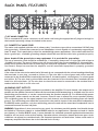
BACK PANEL FEATURES
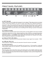
(7) IEC MAINS CONNECTOR
This is a standard IEC power connector. An AC mains cord having the appropriate AC plug and ratings for
the intended operating voltage is included in the carton.
U.S. DOMESTIC AC MAINS CORD
The mains cord supplied with the unit is a heavy-duty, 3-conductor type with a conventional 120 VAC plug
with ground pin. It should be connected to an independent circuit capable of continuously supporting at
least 15 amps. This is particularly critical for sustained high-power applications. If the outlet used does not
have a ground pin, a suitable grounding adapter should be used and the third wire grounded properly.
Never break off the ground pin on any equipment. It is provided for your safety.
The use of extension cords should be avoided but, if necessary, always use a 3-wire type with at least a
#14 AWG wire size. The use of lighter wire will severely limit the power capability of this amplifiers.
Always use a qualified electrician to install any new electrical equipment. To prevent the risk of shock or
fire hazard, always be sure that the amplifier and all associated equipment is properly grounded.
NOTE: FOR UK ONLY.
If the colors of the wires in the mains lead of this unit do not correspond with the colored markings identifying
the terminals in your plug, proceed as follows (1) The wire that is colored green and yellow must be
connected to the terminal that is marked by the letter E, the earth symbol, colored green, or colored green
and yellow. (2) The wire that is colored blue must be connected to the terminal that is marked with the
letter N or the color black. (3) The wire that is colored brown must be connected to the terminal that is
marked with the little L or the color red.
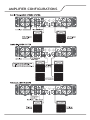
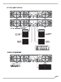
(8) BINDING POST OUTPUTS
Shockproof binding post speaker outputs are provided on the amplifier. For each channel, the outputs are in
parallel and the speaker connection cables can be terminated with banana plugs or stripped wires for use in
the binding post terminals, or can be connected using the Speakon outputs (9). For sustained high-power
applications, either outputs can be used, however, exercise care to assure the correct speaker phasing.
The red binding posts are the signal outputs from each channel, and the black binding posts are chassis
ground. The red binding post should be connected to the positive inputs of the associated loudspeakers.
For BRIDGE mode operation, only the red binding posts are used and the associated loudspeaker load is
connected between the two red posts.
WARNING: Regardless of what connections are used, the minimum parallel speaker load should always
be limited to 2 ohms per channel or 4 ohms BRIDGE mode for any applications. Operation at loads of 4 ohms
per channel, or 8 ohms BRIDGE mode, is more desirable for sustained operation applications because the
amplifier will run much cooler at this loading. Operation above 4 ohms per channel and even open-circuit
conditions can always be considered safe, but sustained operation at loads below 2 ohms could result in
temporary amplifier shut down due to the thermal limit circuitry.