1
POWER MONITORING & PROTECTION
HUMIDITY
We Stock a Wide Variety to Meet Your Energy Management Requirements.
DTK-120SRD | p. 965
E50 Series | p. 927
OVR DIN Series | p. 968
TM
ENG Accessories | p. 919
H Series | p. 930
CS1150A | p. 939
POWER MONITORING
& PROTECTION
POWER MONITORING & PROTECTION
Products manufactured
in the United States
Products that are
new to the catalog
EnGenius | p. 913
SCX Series | p. 950
POWER
MONITORING
& PROTECTION
A/CR-12DC-12A | p. 942
kele.com
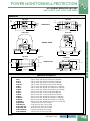
MODEL/SERIESPAGE
Current Operated Switches
RIBXG, RIBXK, RIBXK420 Series — Current-Operated Switches & Transducers . . . .
CS1A, CS1150A-LED, SCS1.5A, SCS1150A-LED — Current-Operated Switches . . .
A/ACS, A/ASCS, A/CS, A/SCS, A/CR Series — ACI Current-Operated Switches. . . .
A/MCS, A/MSCS, A/MCS-A, A/MSCS-A — ACI Mini Current-Operated Switches . . . .
RIBX Series — Functional Devices Current Switch and Relay. . . . . . . . . . . . . . . . . . . .
941
939
942
944
946
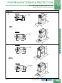
Current, Voltage and Power Monitoring Transducers
EnGenius™ - Patent Pending — Intelligent Power Monitor. . . . . . . . . . . . . . . . . . . . .
ENG-485, PT-NTL-10 — Communication Modules for EnGenius™. . . . . . . . . . . . . . . .
EnGenius™ Accessories — Intelligent Power Monitor Accessories. . . . . . . . . . . . . . .
PQube Series — PQube Power Quality Meters. . . . . . . . . . . . . . . . . . . . . . . . . . . . . . .
PQube Ethernet Modules — Ethernet and Combined CT/Ethernet Modules. . . . . . . .
PQube TH Series — Temperature/Humidity Probe . . . . . . . . . . . . . . . . . . . . . . . . . . . .
PQube DC Voltage Monitors — DC Voltage and Energy Monitors. . . . . . . . . . . . . . . .
E50 Series — E50 Series Power Meter . . . . . . . . . . . . . . . . . . . . . . . . . . . . . . . . . . . . .
H-Series Class 500 Submeters — Advanced KWH/DEMAND Meter. . . . . . . . . . . . . .
U3889, 209PF — Voltage Disconnect Switch Block, Ct Shorting Switches . . . . . . . . . .
4CTV, 4CMA — Kele AC Current Transducer. . . . . . . . . . . . . . . . . . . . . . . . . . . . . . . . .
CX, SCX Series (Current) — AC Current Transducer with Current Output . . . . . . . . . .
CX, SCX Series (Voltage) — AC Current Transducers with Voltage Output . . . . . . . . .
A/CT, A/SCT Series — Current Transducers. . . . . . . . . . . . . . . . . . . . . . . . . . . . . . . . .
RIBX-V Series — Current Transducer and Relay. . . . . . . . . . . . . . . . . . . . . . . . . . . . . .
Sentry 200-A Series — High AC Current Transducers With Current Output . . . . . . . . .
258, 269 — Three-Phase Voltage Monitors. . . . . . . . . . . . . . . . . . . . . . . . . . . . . . . . . . .
201A — MotorSaver™ Three-Phase Voltage Monitor. . . . . . . . . . . . . . . . . . . . . . . . . . .
250A — MotorSaver™ Three-Phase Voltage Monitor. . . . . . . . . . . . . . . . . . . . . . . . . . .
355 Series — MotorSaver™ Three-Phase Voltage Monitor. . . . . . . . . . . . . . . . . . . . . .
455 Series — MotorSaver™ Three-Phase Voltage Monitor. . . . . . . . . . . . . . . . . . . . . .
460 — MotorSaver™ Three-Phase Voltage Monitor. . . . . . . . . . . . . . . . . . . . . . . . . . . .
913
918
919
920
921
924
924
927
930
934
948
950
951
952
953
955
956
957
958
959
960
961
Potential and Current Transformers
PQube XCT CT Modules — Current Transformer Interface Modules . . . . . . . . . . . . . .
PQube SCN Series — High Accuracy Split Core Current Sensors. . . . . . . . . . . . . . . .
PQube DC Sensors — DC Hall Effect Current Sensors . . . . . . . . . . . . . . . . . . . . . . . .
SCT Series — Current Transformers With Voltage Output. . . . . . . . . . . . . . . . . . . . . . .
RCT-1800 Series — Rope CT AC Current Sensor. . . . . . . . . . . . . . . . . . . . . . . . . . . . .
500T, 501T — Split-Core Current Transformers. . . . . . . . . . . . . . . . . . . . . . . . . . . . . . .
600T, 601T — Split-Core Current Transformers. . . . . . . . . . . . . . . . . . . . . . . . . . . . . . .
RL Series — Solid-Core Current Transformers. . . . . . . . . . . . . . . . . . . . . . . . . . . . . . . .
921
922
924
932
933
935
936
937
Power Monitoring & Protection
WNC SERIES — WattNode AC Power Meter. . . . . . . . . . . . . . . . . . . . . . . . . . . . . . . . . 925
UCT Series — Solid Core Current Transformers with Voltage Output . . . . . . . . . . . . . . 938
Protection
DTK-120HW — Surge Protectors. . . . . . . . . . . . . . . . . . . . . . . . . . . . . . . . . . . . . . . . . .
DTK-MRJ11 — Surge Protection . . . . . . . . . . . . . . . . . . . . . . . . . . . . . . . . . . . . . . . . . .
DTK-2LVLP — Surge Protection . . . . . . . . . . . . . . . . . . . . . . . . . . . . . . . . . . . . . . . . . .
DTK-120SR, DTK-2MHLP — Power/Data Surge Protector. . . . . . . . . . . . . . . . . . . . . .
DTK-120SRD, DTK-TSS4D — 54kA Series Connected Surge Protector with
Dry Contacts . . . . . . . . . . . . . . . . . . . . . . . . . . . . . . . . . . . . . . . . . . . . . . . . . . . . . .
DRS, PC642C Series — Data Line Surge Protector . . . . . . . . . . . . . . . . . . . . . . . . . . .
FAS-TEL, HSP-121BT1RU — Power & Data Line Surge Protector. . . . . . . . . . . . . . . .
OVR DIN Series — DIN Rail Mount Surge Protection . . . . . . . . . . . . . . . . . . . . . . . . . .
392-SVSR2 — Lightning Arrester. . . . . . . . . . . . . . . . . . . . . . . . . . . . . . . . . . . . . . . . . .
V130LA1, V39ZA1, V47ZA1, 1.5KE56CA — Metal Oxide Varistor, Transzorb. . . . . . . .
962
962
962
963
965
966
967
968
969
970
NEW!
POWER MONITORING & PROTECTION
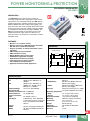
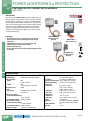
INTELLIGENT POWER MONITOR
ENGENIUS TM - PATENT PENDING
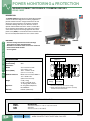
DESCRIPTION
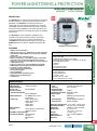
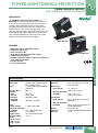
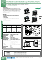
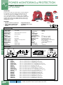
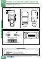
The EnGenius™ is a two processor based power monitoring
device that monitors and records numerous power system
parameters. The EnGenius™ continuously measures
voltage and current to calculate and display over 57 values.
120 to 600V can be monitored without the need of potential
transformers. 601 to 32000 V can be monitored with the use
of potential transformers. All scaling calculations are handled
by the meter.
The Engenius™ comes standard in a NEMA 4 rated
enclosure ready to be mounted. A data port is provided
on the front interface for easy setup and trend retrieval
via EnGenius™ desktop software. Built for the future, the
EnGenius™ allows for feature upgrades through the data
port.
FEATURES
• NEMA 4 enclosure standard
• KWH Accuracy class 0.5% ANSI C12.20 For meter alone with
unmatched CT's OR for Meter-CT set with factory calibrated
matched CT's
• Data port for setup and trend retrieval
• Measure voltages up to 32000 VAC (*voltages over 600VAC
require the use of a potential transformer, not included)
• Supports 0.333V safe CTs and 5 AMP CTs (must use optional
5 AMP adapter board)
• Supports 1V and 2 V CT's (must use ENG-2VT/1V-ADPTR)
• BACnet MSTP, Lonworks, N2 and Modbus RTU available
• Password protected configuration
• Powered by separate 24 VAC supply
• On board data logging
• Auto configuration
• Upgradable firmware through data port
• Bidirectional power measurement
• CSI approved
PARAMETERS
Parameters that can assigned to 4-20 mA output:
• Total Positive KW
• Total Bi-directional KW (12 mA = 0 KW)
• Total Sliding Window KW (user configured, 5 to 60 min.)
• Peak Sliding Window KW
• Total KVA
• Total PF
• Average System Volts
• Average System Amps
Parameters that can be assigned to Digital Outputs:
• Positive KWH pulse
• Negative KWH pulse
• Low volts - alarm
• Unbalanced volts - alarm
• Low or unbalanced volts - alarm
16
SPECIFICATIONS
Supply Voltage
24 VAC ± 10% 60Hz
Supply Current
250 mA maximum
Monitored Voltage
Line to Line 120 to 600 VAC
Line to Line with
potential transformer
601 to 32000 VAC
Monitored Current
5 to 6000A using current
transformers
System Type
2-Wire Single Phase
3-Wire Single Phase
4-Wire Wye
3-Wire Delta
4-Wire Delta
Communication
Data Port Serial interface to EnGenius™
Desktop Software
OPTIONAL Communications
(not field installable) BACnet MS/TP
Lonworks
Modbus RTU
N2
March 2014
POWER MONITORING & PROTECTION
EnGenius™ Patent Pending
Analog Output
1 Output Type 4-20 mA (loop powered)
Accuracy 0.5% full scale
Maximum Loop
Supply Voltage 30 VDC
Maximum Impedance 850Ω @ 24 VDC
Digital Output
2 Outputs
Type Optically isolated solid state
FET switch
Rated Voltage 28 VAC/40 VDC maximum
Rated Current 00 mA maximum
Operating Temperature -22° to 158°F (-30° to 70°C)
Operating Humidity
0 to 95% (non-condensing)
Enclosure
NEMA 4, UL94 rated 5VA
Dimensions
6.5” x 6.5” x 4”
(16.5 x 16.5 x 10.1 cm)
Weight
3.1 lb (1.4 kg)
Approvals
ETL, CE File #4004284
RoHS Statement
Yes
Warranty
1 year
WE MAKE IT EASY.
kele.com
888-397-5353 USA
913
NEW!
POWER MONITORING & PROTECTION
INTELLIGENT POWER MONITOR
ENGENIUS TM - PATENT PENDING
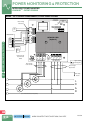
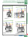
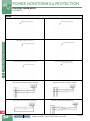
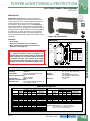
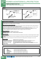
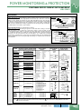
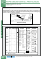
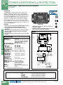
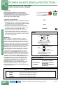
WIRING - .333 V CURRENT TRANSFORMERS, 3-PHASE POWER SYSTEMS
APPLY 24VAC POWER
BEFORE MOVING JUMPER
FROM OFF TO ON
Route Through
Le Conduit
BATTERY
JUMPER
CR2032
BATTERY
OFF ON
CONTACT 24 VOLT
2
POWER
FRONT PANEL
24 VAC
POWER
SUPPLY
NETWORK CARD
CABLE RIBBON
Building Automaon Device
MA OUT CONTACT
1
ALARM
OR
PULSE
OUTPUT
ALARM
OR
PULSE
OUTPUT
POWER MONITORING & PROTECTION
Building Automaon De
NETWORK CARD
(Oponal)
ALARM
OR
PULSE
OUTPUT
ALARM
OR
PULSE
OUTPUT
+
4 – 20 MA
-
+
4 – 20 MA
-
24 VDC POWER
SUPPLY +
* READ ALL INSTALLATION INSTRUCTIONS *
X2
X1
CTC
FUNCTIONAL
EARTH
X2
X1
CTB
X2
X1
CTA
0.333V CT INPUTS
N
RISK OF
ELECTRIC
SHOCK
Earth Ground for
CT/Comm Cable
Shields
L1
L2
L3
SYSTEM VOLTAGE INPUTS
120 – 600 VOLTS AC
Route Through
Center Conduit
16
Route Through
Right Conduit
H1
CTA
0.333V
L1
H1
CTB
0.333V
L2
H1
L3
N
914
Lug on conduit
bonding plate
CTC
0.333V
Earth Safety
Ground
L
O
A
D
L2
L3
N
(For 3-Wire Delta neutral not present)
888-397-5353 USA
kele.com
WHEN YOU NEED IT RIGHT, RIGHT NOW, CALL KELE.
L1
March 2014
NEW!
POWER MONITORING & PROTECTION
INTELLIGENT POWER MONITOR
ENGENIUS TM - PATENT PENDING
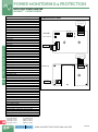
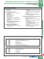
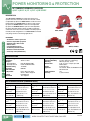
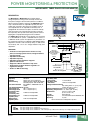
WIRING - 5 AMP CURRENT TRANSFORMERS, 3-PHASE POWER SYSTEMS
APPLY 24VAC POWER
BEFORE MOVING JUMPER
FROM OFF TO ON
Route Through
Le Conduit
BATTERY
JUMPER
OFF ON
FRONT PANEL
CONTACT 24 VOLT
2
POWER
24 VAC
POWER
SUPPLY
CR2032
BATTERY
NETWORK CARD
CABLE RIBBON
MA OUT CONTACT
1
Building Automaon Device
ALARM
OR
PULSE
OUTPUT
+
4 – 20 MA
-
24 VDC POWER
SUPPLY +
RA
RB
X1
CTB
X2
N
X1
CTA
0.333V CT INPUTS
L1
L2
L3
SYSTEM VOLTAGE INPUTS
120 – 600 VOLTS AC
Lug on conduit
bonding plate
2V/1V CT INPUTS
CTA
CTC5 AMP
CTB
CTA
X2 X1 X2 X1 X2
X1
H1
RISK OF
ELECTRIC
SHOCK
L1
HDR4
+
CTB
5 AMP
L2
H1
L3
Route Through
Right Conduit
ENG-2V/1V-ADPTR
INSTALL
JUMPERS
FOR 2V CTS
L
O
A
D
CTC
5 AMP
*Use 2v CT
N
Earth Safety
Ground
16
(For 3-Wire Delta neutral not present)
2V/1V CT INPUTS
CTC
CTB
CTA
X2 X1 X2 X1 X2 X1
*Use 2v CT
*Use 1v CT
March 2014
+
RISK OF
ELECTRIC
SHOCK
RISK OF
ELECTRIC
SHOCK
2V/1V CT INPUTS
CTC
CTB
CTA
X2 X1 X2 X1 X2 X1
INSTALL
JUMPERS
FOR 2V CTS
HDR4
+
ENG-2V/1V-ADPTR
INSTALL
JUMPERS
FOR 1V CTS
ENG-2V/1V-ADPTR
2V CT INPUTS
1V CT INPUTS
HDR4
L
O
A
D
X2
Route Through
Center Conduit
H1
Earth Safety
Ground
X1
CTC
FUNCTIONAL
RA
EARTH
Lug on conduit
bonding plate
5 AMP CT INPUTS
X2CTBX1
X2CTAX1
X2CTCX1
X2
RISK OF
ELECTRIC
RISK OF
SHOCK
ELECTRIC
SHOCK
Shown with oponal
5 AMP Adapter Board
*See addi onal CT INPUT
diagrams below.
gh
t
* READ ALL INSTALLATION INSTRUCTIONS *
A
B
C
POWER MONITORING & PROTECTION
ALARM
OR
PULSE
OUTPUT
NETWORK CARD
(Oponal)
WE MAKE IT EASY.
kele.com
888-397-5353 USA
915
NEW!
POWER MONITORING & PROTECTION
COMMUNICATION CARDS
TO ENGENIUS MAIN BOARD
IN1
IN2
GND
MODULE
STATUS
(BACnet, Modbus, N2)
TX
RX
A(+)
RS-485 Network
ENG-485
ENG-485
RIBBON CABLE
B (-)
GND
TO ENGENIUS MAIN BOARD
PT-NTL-10
RIBBON CABLE
LonWorks Network
LONWORKS
FT-10 NWK
16
Parameters Available Via Display/Network*
Total KW*
Total Sliding Window KW (period programmable 5-60 minutes)
Total KVAR
Total KVA*
Phase A KW*
Phase B KW*
Phase C KW*
Phase A KVAR*
Phase B KVAR*
Phase C KVAR*
Phase A KVA
Phase B KVA
Phase C KVA
Total PF*
Phase A PF*
Phase B PF*
Phase C PF*
Average L-N Volts
Average L-L Volts
L1-L2 Volts**
L2-L3 Volts**
L3-L1 Volts**
L1-N Volts**
L2-N Volts**
L3-N Volts**
Average Amps
Phase A Amps*
Phase B Amps*
Phase C Amps*
Total Positive KWH*
Total Negative KWH
Total Absolute KWH (Sum of positive and negative )
Total Net KWH (Positive minus negative)
Phase A Positive KWH
Phase B Positive KWH
Phase C Positive KWH
Phase A Negative KWH
Phase B Negative KWH
Phase C Negative KWH
Total Positive KVARH
Total Negative KVARH
Total Absolute KVARH
Total Net KVARH
Phase A Positive KVARH
Phase B Positive KVARH
Phase C Positive KVARH
Phase A Negative KVARH
Phase B Negative KVARH
Phase C Negative KVARH
Timestamp (When energy counters were last cleared)
Peak Sliding Window KW (since last cleared)*
Timestamp (when Peak Sliding Window occured)
Timestamp (when Peak Sliding Window KW was last cleared)
RS-485 NETWORK
POWER MONITORING & PROTECTION
INTELLIGENT POWER MONITOR
ENGENIUS TM - PATENT PENDING
*ONLY Values with asterisk are available for LONWORKS
** For Delta System
For WYE System
Phase A = L1-L2
Phase A = L1-N
Phase B = L2-L3
Phase B = L2-N
Phase C = L3-L1
Phase C = L3-N
916
888-397-5353 USA
kele.com
WHEN YOU NEED IT RIGHT, RIGHT NOW, CALL KELE.
March 2014
NEW!
POWER MONITORING & PROTECTION
INTELLIGENT POWER MONITOR
ENGENIUS TM - PATENT PENDING
ORDERING INFORMATION
ENG
EnGenius Intelligent Power Monitor
9000 .333V input
9500 5 Amp input
BACnet Communication Board
B
L
M
N
LonWorks Communication Board
Modbus Communication Board
N2 Communication Board
Display
T
Trend Data Logging
Example: ENG-9000-B-D = EnGenius .333V input with BACnet and display.
ENG-9000-B-D-T = Additional feature of trend data logging.
Note: CT’s are ordered separately and not included in the above part numbers.
March 2014
ENG-2V/1V-ADPTR
ENG-485
ENG-5AMPBRD
ENG-CABLE
ENG-SOFTWARE
PT-NTL-10
ACCESSORIESPAGE
2V or 1V input adapter board for ENG-9000
919
BACnet, Modbus, N2 Communication Board
918
5 Amp Input adapter board for ENG-9000
919
Data Cable for EnGenius™
919
Desktop Software for EnGenius™
919
LonWorks communications module
918
500T, 501T
600T, 601T
RCT-1800 Series
SCT Series
UCT Series
RELATED PRODUCTS
Split-Core Current Transformer, 5A Secondary
Split-Core Current Transformer, 5A Secondary
Rogowski Coil Flexible Current Sensor, 0.333V Secondary
Split-Core Current Transformer, 0.333V Secondary
Solid-Core Current Transformer, 0.333V Secondary
WE MAKE IT EASY.
POWER MONITORING & PROTECTION
D
16
PAGE
935
935
933
932
938
kele.com
888-397-5353 USA
917
NEW!
POWER MONITORING & PROTECTION
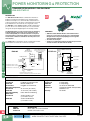
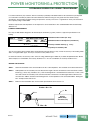
COMMUNICATION MODULES FOR ENGENIUS™
ENG-485, PT-NTL-10
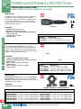
DESCRIPTION
The ENG-485 and PT-NTL-10 are communication modules for
EnGenius™ Intelligent Power Monitor. They read data from the
EnGenius™ main processor, format the data, and transmit it to a
network. They allow all of the power system parameters measured
by the EnGenius™ to be monitored over a single pair of wires.
The ENG-485 contains BACNET, Modbus and N2 communication
protocols. The chosen communication protocol is selected either
through the front panel display/keypad or the desktop software.
ENG-485
POWER MONITORING & PROTECTION
The ENG-485 features 2 contact-closure inputs for monitoing
external equipment. Each input can be configured to read
contact state (On/Off) or as a Pulse Counter to count pulses
from flow meters or other power meters. In the Pulse Counter
mode, a Clear command is available to reset the pulse count
when desired.
FEATURES
• ENG-485 contains BACnet, Modbus & N2 communication
protocols on one board. The chosen one is selected either
through the the front panel display/keypad or through the
optional Desktop Software.
• 2 Contact-closure inputs
• PT-NTL-10 is a dedicated Lonworks module. This protocol has
a subset of values. See data sheet for details.
The PT-NTL-10 is a a dedicated Lonworks communication module.
This module does not have the 2 contact-closure inputs.
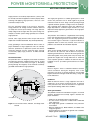
WIRING
Ribbon Cable
Plugs Into EnGenius Main Board
(Disconnect 24 VAC power before
plugging or unplugging)
Optional
External Status or
Pulse Count contacts
ENG-485
PT-NTL-10
Ribbon
Cable
PT-NTL-10
2
1
Module Status LED
Service Button
IN1 IN2 GND
Service LED
Receive Data,
Transmit Data
Statuts LEDs
RX
TX
RS-485 Twisted Pair ‘A’ Conductor
Mounting Holes
A(+)
B(–)
GND
RS-485 Twisted Pair ‘B’ Conductor
RS-485 Reference Conductor (if used)
FTT-10
CONTROL
MODULE
FT-10 NWK
ENG-485
RS-485 Communications
Terminals
Status
LED
RS-485 twisted pair is polarity sensitive.
If unable to communicate, try reversing the ‘A’ and ‘B’ conductors.
16
Not Polarity
Sensitive
To LonWorks
FT-10 Network
SPECIFICATIONS
Communication
PT-NTL-10
LonWorks FTT-10 transceiver
ENG-485
BACNet, Modbus, N2
Connections
Pluggable screw terminals
Operating Temperature
PT-NTL-10
32° to 122°F (0° to 50°C)
ENG-485
14° to 122°F (-10° to 50°C)
Operating Humidity
0-95% RH non-condensing
Dimensions
PT-NTL-10
4.5"H x 2.6"W x 1.7"D
(11.4 x 6.6 x 4.3 cm)
ENG-485
4.5"H x 2.6"W x 0.6"D
(11.4 x 6.6 x 1.5cm)
Weight
PT-NTL-10
ENG-485
Approvals
PT-NTL-10
Warranty
0.7 lb (0.32kg)
0.1 lb (0.05 kg)
UL listed, File #E161500
Certified to LonMark Interoperability
Guidelines v 3.1
18 months
ORDERING INFORMATION
MODEL
ENG-485
PT-NTL-10
918
888-397-5353 USA
DESCRIPTION
BACnet, Modbus, N2 Communication Board
LonWorks communications module
kele.com
WHEN YOU NEED IT RIGHT, RIGHT NOW, CALL KELE.
March 2014
NEW!
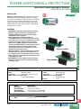
POWER MONITORING & PROTECTION
INTELLIGENT POWER MONITOR ACCESSORIES
ENGENIUS™ ACCESSORIES
DESCRIPTION
EnGenius™ Accessories help you get the most out of the
EnGenius power monitor. With these and future available
accessories, the EnGenius can be kept up to date. Available
accessories are the software, data cable, 5 Amp CT input
adapter board and a safe current transformer 2V/1V input
adapter board. The 2V/1V adapter board is configurable to
the application you need.
ENG-SOFTWARE
FEATURES
• ENG-CABLE - LED lights indicate when the Desktop
Software is being transmitted to the EnGenius™
intelligent power monitor and when data is being
downloaded into the computer.
• ENG-SOFTWARE - The Desktop Software is
conveniently loaded on this flash drive. This software
will enable you to easily and conveniently interact with
EnGenius™ intelligent power monitor via the data
cable. You can quickly program one power monitor,
save to your desktop/laptop and then program several
more power monitors in a timely fashion. You will
also be able to download the information from the
EnGenius™ and analyze the data.
• ENG-2V/1V-ADPTR - Use this adapter board to retrofit
an EnGenius™ to accept safe CTs with either 2V or
1V secondary output. The same board can be used for
either application. Just change the DIP switches to the
configuration you need.
• ENG-5AMPBD - Use this adapter board to retrofit an
EnGenius™ to accept current transformers with 5A
secondary output.
ENG-CABLE
ENG-5AMPBRD
POWER MONITORING & PROTECTION
ENG-2V/1V-ADPTR
16
SPECIFICATIONS
Dimensions
Cable 36" (0.9m) length
Flash Drive 2.25" x 0.625" (5.72 x 1.59 cm)
5AMP and 2V/1V Adapter boards 2" x 3.5" (5.08 x 8.89cm)
Weight
Cable
0.55 lb (0.25 kg)
Flash Drive
0.01 lb (0.004 kg)
5AMP and 2V/1V Adapter boards
0.35 lb (0.16 kg)
Warranty
1 year
ORDERING INFORMATION
March 2014
MODEL
ENG-CABLE
ENG-SOFTWARE
ENG-5AMPBRD
ENG-2V/1V-ADPTR
DESCRIPTION
Data Cable for EnGenius™
Desktop Software for EnGenius™
5 Amp Input adapter board for ENG-9000
2V or 1V input adapter board for ENG-9000
AH04
RELATED PRODUCTS
Fuse pack, 3 Phase
WE MAKE IT EASY.
kele.com
888-397-5353 USA
919
NEW!
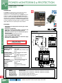
POWER MONITORING & PROTECTION
POWER QUALITY METERS
PQUBE SERIES
DESCRIPTION
The PQube is a high-precision power quality and energy
monitor. This will record the details of every power
disturbance on a removable SD card. The PQube AC power
monitor can handle up to 690V, 50/60/400Hz three-phase
systems. It will recored voltage dips, swells and interruptions
and will give you waveforms and RMS graphs. No software is
required, the programming is embedded. The PQube system
hsa been designed to be plug and play so modules are easily
added. DIN rail mount or optional panel mount bracket.
PS1
16
CAUTION: MUST HAVE EARTH GROUND
TO WORK PROPERLY
PQube
DIMENSIONS
in.
(mm)
3.01”
(76.5)
2.82”
(71.7)
1.13”
(28.6)
3.54”
(89.9)
• Three-phase and single phase monitoring up to 690V,
50/60/400Hz
• Auto power configuration
• Voltge dips, swells, and interruptions - waveforms and
RMS graphs - recorded on removable SD card
• Email alerts and Excel reports available with optional
ethernet module
• 1-microsecond high-frequencey events
• Power from 24VAC, 24VDC~48VDC
• Optional power supply modules for 100V~240V supply
• All modules are DIN rail mount
1.76”
(44.8)
POWER MONITORING & PROTECTION
FEATURES
SPECIFICATIONS
Supply Voltage
Monitored Voltage
System Type
24 VAC 60/60 Hz 5 VA, 24-48 VDC
100 to 690V
Three-phase (Wye or Delta), singlephase
Frequency Range
40 to 70 Hz and 320 to 560 Hz
Measurement ChannelsL-N, L-L, N-E
Monitored Current
Up to 6000 A with input module
Relay Output
30 VAC/VDC, 300 mA max
Communication Connection
Mini-B USB socket
Data Storage
4 GB Scan Disk card (included)
Operating Temperature-4° to 122°F (-20° to 50°C)
Operating Humidity
up to 95% RH
Mounting
DIN rail
Weight
0.73 lbs (0.331 kg)
Approvals
CE, RoHS, UL file#E220936
Warranty
1 year
N
15
L3
13
L2
11
L1
9
Selector
Button
Joystick
21 22 23 24
Digital In
29 30 31 32
Earth
-
Relay Out
Analog In
22 & 30
+
23 & 31
Power In
24VAC
24-48VDC
ORDERING INFORMATION
MODEL
PQube-02-0000
PQube-02-0100
PS1-100~240-00
ENCL-EXT1074-01
PQUBE BATTERY
920
888-397-5353 USA
DESCRIPTION
PQube power quality meter-4 AC voltage inputs, 2 analog inputs, 1 digital input, 1 relay output
PQube power quality meter-4 AC voltage inputs, 2 analog inputs, 1 digital input, 4 relay outputs
Power supply PQube from 100V~240V, 50/60 Hz
Enclosure for PQube Assembly, 10 x 7.2 x 4.3", IP65 rated
Replacement battery, lithium polymer; 0.6 AMP-hour
kele.com
WHEN YOU NEED IT RIGHT, RIGHT NOW, CALL KELE.
March 2014
NEW!
POWER MONITORING & PROTECTION
CURRENT TRANSFORMER INTERFACE MODULES
PQUBE XCT, CT, ETHERNET MODULES
DESCRIPTION
The XCT current transformer modules connects your existing CT's
to your PQube. The external CT input ratio range is 1:1 to 1000:1. The
XCT4 Series connect directly to current transformer secondary wires
and has 4 channels of current monitoring. The XCT5 Series connects
directly to voltage output current transformer wires and has 5 channels
of current monitoring. The CT4 is a current sensing module that has
20Amp input. Just feed the wires through the opening.
FEATURES
XCT4
• Accuracy ±1% (plus uncertainty of external CT's)
• Adds current waveforms to PQube events
• Enables power consumption and energy monitoring
• Crest factor typically 3.5 times rated input
SPECIFICATIONS
XCT5
POWER MONITORING & PROTECTION
• 2.8"W x 3.5"H x 3.2"L (7.1 x 8.9 x 8.1 cm)
• 0.5 lbs (0.22 kg)
ORDERING INFORMATION
MODEL
XCT4-1A-00
XCT4-5A-00
XCT5-0.333V-00
XCT5-1V-00
XCT5-5V-00
XCT5-10V-00
CT4-20A-00
DESCRIPTION
Interface module for CT's with 1 Amp output
Interface module for CT's with 5 Amp output
Interface module for CT's with 0.333V output
Interface module for CT's with 1V output
Interface module for CT's with 5V output
Interface module for CT's with 10V output
Current sensing module 20Amp input
DESCRIPTION
The ETH1 Ethernet module automatically sends you an email
whenever a disturbance occurs, complete with picture and Excel
compatible attachments. The CTE1 Modules combine the XCT5
current sensing and the ETH1 ethernet into a single package.
16
FEATURES
• Built in web server
• See status of the PQube and look at event and trend
recordings
• Update firmware and reset remotely
• Free email account with each PQube
• Synchronize to UTC time standard
• DHCP/Fixed IP, POP, SMTP, FTP, Modbus/TCP
CTE1
SPECIFICATIONS
• 2.8"W x 3.5"H x 3.2"L (7.1 x 8.9 x 8.1 cm)
• 0.5 lbs (0.22 kg)
ETH1
ORDERING INFORMATION
MODEL
ETH1-10T-00
CTE110T0.333V00
CTE1-10T-1V-00
CTE1-10T-5V-00
CTE1-10T-10V-00
March 2014
DESCRIPTION
Ethernet module with email account
Combined ethernet & CT module for 0.333V CT's
Combined ethernet & CT module for 1V CT's
Combined ethernet & CT module for 5V CT's
Combined ethernet & CT module for 10V CT's
WE MAKE IT EASY.
kele.com
888-397-5353 USA
921
NEW!
POWER MONITORING & PROTECTION
HIGH ACCURACY SPLIT CORE CURRENT SENSORS
PQUBE SCN SERIES
DESCRIPTION
These SCN Series of split core current sensors easily clamp
around existing conductors. They range from 1A - 600A
primary input/ 333mV output. They are for use with the XCT5
and CTE1 Series of current transformer interface modules.
FEATURES
•
•
•
•
•
Accuracy ± 0.2%
Phase angle: 0.2 °
Crest factor 3.5 times nominal CT rating
8ft. leads, 18 AWG twisted pair
1 year warranty
SCN Snaptop
DIMENSIONS
POWER MONITORING & PROTECTION
PSL Part Number
D
A
E
B
16
C
Dimensions - mm (inches)
A
B
C
D
E
SCN2-1A:333mV-0.4
61
(2.40")
42
(1.65")
29
(1.12")
10
(0.4")
10
(0.4")
SCN2-5A:333mV-0.4
61
(2.40")
42
(1.65")
29
(1.12")
10
(0.4")
10
(0.4")
SCN3-20A:333mV-0.7
78
(3.08")
60
(2.37")
29
(1.12")
18
(0.7")
18
(0.7")
SCN3-50A:333mV-0.7
78
(3.08")
60
(2.37")
29
(1.12")
18
(0.7")
18
(0.7")
SCN3-100A:333mV-0.7
78
(3.08")
60
(2.37")
29
(1.12")
18
(0.7")
18
(0.7")
SCN3-150A:333mV-0.7
78
(3.08")
60
(2.37")
29
(1.12")
18
(0.7")
18
(0.7")
SCN4-200A:333mV-1.25
83
(3.27")
81
(3.17")
35
(1.39")
32
(1.25")
32
(1.25")
SCN4-300A:333mV-1.25
83
(3.27")
81
(3.17")
35
(1.39")
32
(1.25")
32
(1.25")
SCN4-400A:333mV-1.25
83
(3.27")
81
(3.17")
35
(1.39")
32
(1.25")
32
(1.25")
SCN4-500A:333mV-1.25
83
(3.27")
81
(3.17")
35
(1.39")
32
(1.25")
32
(1.25")
SCN4-600A:333mV-1.25
83
(3.27")
81
(3.17")
35
(1.39")
32
(1.25")
32
(1.25")
ORDERING INFORMATION
MODEL
DESCRIPTION
SCN2-1A:333mV-0.4 0.2% accuracy;1A:333mV; 0.4"X0.4"
SCN2-5A:333mV-0.4 0.2% accuracy;5A:333mV; 0.4"X0.4"
SCN3-20A:333mV-0.7 0.2% accuracy;20A:333mV; 0.7"X0.7"
SCN3-50A:333mV-0.7 0.2% accuracy;50A:333mV; 0.7"X0.7"
SCN3-100A:333mV-0.70.2% accuracy;100A:333mV; 0.7"X0.7"
SCN3-150A:333mV-0.70.2% accuracy;150A:333mV; 0.7"X0.7"
922
888-397-5353 USA
kele.com
MODEL
SCN4-200A:333mV-1.25
SCN4-300A:333mV-1.25
SCN4-400A:333mV-1.25
SCN4-500A:333mV-1.25
SCN4-600A:333mV-1.25
DESCRIPTION
0.2% accuracy;200A:333mV; 1.25"X1.25"
0.2% accuracy;300A:333mV; 1.25"X1.25"
0.2% accuracy;400A:333mV; 1.25"X1.25"
0.2% accuracy;500A:333mV; 1.25"X1.25"
0.2% accuracy;600A:333mV; 1.25"X1.25"
WHEN YOU NEED IT RIGHT, RIGHT NOW, CALL KELE.
March 2014
NEW!
POWER MONITORING & PROTECTION
POWER QUALITY METERS
PQUBE WIRING DIAGRAM
WIRING
PE
PE
L3
L3
L2
L2
L1
L1
13
11
9
9
L1
L2
L3
11
POWER MONITORING & PROTECTION
N
13
32
32
PQUBE MONITORS COMPLETE
VOLTAGE QUALITY
WITH CT4 CURRENT MODULE
PE
PE
16
L3
L3
L2
L1
L2
6 5
4 3
2 1
13
11
9
L1
6 5
4 3
2 1
13
11
9
32
WITH XCT5/CTE1 CURRENT MODULE, 3 CURRENT
TRANSFORMERS − PQUBE MEASURES CURRENT
ON ALL PHASES
March 2014
32
WITH XCT4 CURRENT MODULE, 3 CURRENT TRANSFORMERS
− PQUBE MEASURES CURRENT ON ALL PHASES
WE MAKE IT EASY.
kele.com
888-397-5353 USA
923
NEW!
POWER MONITORING & PROTECTION
TEMPERATURE/HUMIDITY PROBE
PQUBE TH SERIES, DC VOLTAGE MONITORS, DC SENSORS
DESCRIPTION
The TH1 probe monitors ambient temperature and humidity.
The PQube can now record temperature and humidity
events with the addition of the probe. Every PQube accepts
2 electrically isolated probes. Use one for local conditions
and the other on the optional 10 meter extension cable for
monitoring remote conditions.
TH Series
FEATURES
POWER MONITORING & PROTECTION
• Temperature accuracy ± 0.5°C
• Max temp -4 to 176°F (-20 to 80°C)
• Humidity accuracy ±4.5% RH (20-80% RH) maximum
±7.5% 10-100% RH
• 1.42 x 0.6" (3.61 x 1.53cm)
• 0.4 lb (0.018 kg)
16
ORDERING INFORMATION
MODEL
DESCRIPTION
TH1-80C-00 TH1 temperature/humidity probe
THC-2M-00 Extension cable for TH180C-00; 2 meter length (6ft. 6.74")
DESCRIPTION
Compact DC Voltage Attenuators connect to PQube's
analog channels. This can be used to monitor high voltage
DC power. ATT1 models measure 1 differential voltge or 2
voltages relative to earth. ATT2 model measured DC voltage
and DC current (with Hall effect sensors).
ATT1
FEATURES
•
•
•
•
•
•
•
± 600VDC or 1200VDC (CAT IV 300VAC)
Termnals are standard shrouded safety banana jacks
Shielded cables
ATT1 = 4 x 2 x 1.5" (10.2 x 5.1 x 3.8cm)
1.08 lb (0.49 kg)
ATT2 = 5 x 2.6 x 1.2" (12.7 x 6.6 x 3.0cm)
3.40 lb (1.54 kg)
ATT2
ORDERING INFORMATION
MODEL
ATT1-0600V-00
ATT1-1200V-00
ATT2-0600V-00
ATT2-1200V-00
DESCRIPTION
Voltage module ±600VDC (CAT lV 300VAC)
Voltage module ±1200VDC (CAT lV 300VAC)
Voltage/current module ±600VDC (CAT lV 300VAC)
Voltage/current module ±1200VDC (CAT lV 300VAC)
DESCRIPTION
DC Hall Effect Sensors are for use with the ATT2 Voltage /
Current Modules. They measure AC or DC current. 50A to
600A primary input to ±4V output. They are powered fromt he
DC output of the ATT2 module.
FEATURES
• Measures AC or DC current
SCSDC-O-0050:4V CSDC-RCL0050:4V
ORDERING INFORMATION
MODEL
CSDC-RCL0050:4V
CSDC-RCL0100:4V
CSDC-RCL0200:4V
CSDC-RCL0400:4V
CSDC-RCL0600:4V
924
DESCRIPTION
DC current sensor,solid core, 50A:4V 0.81X0.41"
DC current sensor,solid core, 100A:4V 0.81X0.41"
DC current sensor,solid core, 200A:4V 0.81X0.41"
DC current sensor,solid core, 400A:4V 0.81X0.41"
DC current sensor,solid core, 600A:4V 0.81X0.41"
888-397-5353 USA
kele.com
MODEL
SCSDC-O-0050:4V
SCSDC-O-0100:4V
SCSDC-O-0200:4V
SCSDC-O-0400:4V
SCSDC-O-0600:4V
DESCRIPTION
DC current sensor, split-core, 50A:4V 0.83" dia.
DC current sensor, split-core, 100A:4V 0.83" dia.
DC current sensor, split-core, 200A:4V 0.83" dia.
DC current sensor, split-core, 400A:4V 0.83" dia.
DC current sensor, split-core, 600A:4V 0.83" dia.
WHEN YOU NEED IT RIGHT, RIGHT NOW, CALL KELE.
March 2014
NEW!
POWER MONITORING & PROTECTION
WATTNODE AC POWER METER
WNC SERIES
DESCRIPTION
WNC Series of AC Power measurement meters are available
in pulse output or will support several communication
protocol outputs. True power, kWh reactive power, VARs,
power factor, and indivitdual phase measurements.
Diagnostic LEDs provide a per-phase indication of power
(green flashing) and negative power (red flashing) to help
troubleshoot connection problems such as swapped CT's
or excessive live voltage. The meters use the safe Ct's
producing 0.333 VAC at rated current. They have a small
form factor for easy installation inside most electrical panels
with pluggable screw terminals for easy wiring. Power
Related Measurements - 50+ for BACnet and Modbus; 27+
for LonWorks.
FEATURES
BACnet, Modbus, Lonworks or Pulse
1 to 3 Phase 120VAC to 600VAC
0.5% nominal accuracy (see manual for details)
Euroblock style pluggable screw terminal blocks
Line powered
Uses safe current transformers; 0.333V output
Bidirectional
WNC Series
POWER MONITORING & PROTECTION
•
•
•
•
•
•
•
SPECIFICATIONS
A−, D0, RxD−/TxD−
B+, D1, RxD+/TxD+
Common
B+
C
WHITE
BLACK
WHITE
BLACK
Shorting
Jumper
ØA CT
Status
ØA
ØB CT
Status
ØB
ØC CT
Status
ØC
Source
Faces
AB+
C
WATTNODE BACNET
®
MS/ TP
EIA-485
A−, D0, RxD−/TxD−
B+, D1, RxD+/TxD+
Common
Com
N
X
WHITE
BLACK
Shorting
Jumper
Ground
WNC- 3D-240-BN
ØA CT
Status
ØA
ØB CT
Status
ØB
ØC CT
Status
ØC
Source
Faces
Current
Transformers
Phase A
LINE
Drawn to Scale
1.50 (3.8) High
16
Single Phase Three-Wire, Mid-Point Neutral Wire
LOAD
(0.5)
Neutral
Phase B
5.375 (13.66)
Ø 0.200
Phase A
120 VAC
120 VAC
WHITE
BLACK
3.35
(8.5)
March 2014
N
Current
Transformers
3.35 (8.5 )
0.386 (1.0)
Ground
WNC- 3Y-208-BN
WNC- 3D-240-BN
240 VAC
6.1 (15.5)
Ø
Com
X
PC or BACnet Host
in
(cm)
WATTNODE BACNET
®
A-
MS/ TP
EIA-485
PC or BACnet Host
LINE
DIMENSIONS
WIRING
LOAD
Supply Voltage
120 to 600VAC
CT Input 0.333V nominal, 3V maximum
Operating Temperature-22°F to 131°F (-30°C to 55°C)
Operating Humidity
5 to 90% RH up to 104°F (40°C)
Dimensions 6.1" x 3.35" x 1.5"
(15.5 x 8.5 x 3.8 cm)
Weight
11oz.
RoHS Statement
Yes
Warranty
5 Years
Communication Protocol
BACnet MS/TP (RS-485)
Modbus RTU
LonWorks Network Variables (SNVTs)
Meets ARRA or BAA Yes
Signal LEDs
Diagnostic LEDs Provide per-phase
indication of power (green flashing)
and negative power (red flashing)
on BACnet, Modbus and Pulse
models only
Approvals CE, UL & cUL File #312220 FCC
Class B, EN 55022 Class B
Additional Specifications
Assembled in the USA
208-240 VAC
Phase B
Single Phase Two-Wire without Neutral
WE MAKE IT EASY.
kele.com
888-397-5353 USA
925
NEW!
POWER MONITORING & PROTECTION
WATTNODE AC POWER METER
WNC SERIES
WIRING
B+
C
WATTNODE BACNET
PC or BACnet Host
®
Com
Ground
WNC- 3Y-xxx-BN
WNC- 3D-xxx-BN
N
X
A−, D0, RxD−/TxD−
B+, D1, RxD+/TxD+
Common
A-
B+
C
WATTNODE BACNET
®
MS/ TP
A-
EIA-485
A−, D0, RxD−/TxD−
B+, D1, RxD+/TxD+
Common
MS/ TP
EIA-485
PC or BACnet Host
Com
N
ØA CT
Status
ØA
ØB CT
Status
ØB
ØC CT
Status
WHITE
BLACK
ØC
Source
Faces
POWER MONITORING & PROTECTION
ØA
Status
ØB
ØC CT
Status
ØC
Neutral
Three Phase Four-Wire Wye
Phase A
Phase B
Current
Transformers
LINE
926
Status
LOAD
Current
Transformers
LINE
LOAD
Phase C
ØA CT
ØB CT
Source
Faces
Phase A
Phase B
16
WHITE
BLACK
WHITE
BLACK
WHITE
BLACK
WHITE
BLACK
X
WHITE
BLACK
Ground
WNC- 3D-xxx-BN
Phase C
Three Phase Three-Wire Delta without Neutral
ORDERING INFORMATION
MODEL
DESCRIPTION
WNC-3Y-208-BN
3 Phase 4 Wire 120V/208V BACnet
WNC-3Y-400-BN
3 Phase 4 Wire 230V/400V BACnet
WNC-3Y-480-BN
3 Phase 4Wire 277V/480V BACnet
WNC-3Y-600-BN
3 Phase 4 Wire 347V/600V BACnet
WNC-3D-240-BN
3 Phase 3 Wire 120V/208V BACnet
WNC-3D-400-BN
3 Phase 3 Wire 230V/400V BACnet
WNC-3D-480-BN
3 Phase 3Wire 277V/480V BACnet
WNC-3D-240-MB
3 Phase 3 Wire 120V/208V Modbus
WNC-3D-400-MB
3 Phase 3 Wire 230V/400V Modbus
WNC-3D-480-MB
3 Phase 3Wire 277V/480V Modbus
WNC-3Y-400-MB
3 Phase 4 Wire 230V/400V Modbus
WNC-3Y-208-MB
3 Phase 4 Wire 120V/208V Modbus
WNC-3Y-480-MB
3 Phase 4Wire 277V/480V Modbus
WNC-3Y-600-MB
3 Phase 4 Wire 347V/600V Modbus
WNC-3D-240-P
3 Phase 3 Wire 120V/208V Pulse
WNC-3D-400-P
3 Phase 3 Wire 230V/400V Pulse
WNC-3D-480-P
3 Phase 3Wire 277V/480V Pulse
WNC-3Y-208-P
3 Phase 4 Wire 120V/208V Pulse
WNC-3Y-400-P
3 Phase 4 Wire 230V/400V Pulse
WNC-3Y-480-P
3 Phase 4Wire 277V/480V Pulse
WNC-3Y-600-P
3 Phase 4 Wire 347V/600V Modbus
WNC-3Y-208-FT10
3 Phase 4 Wire 120V/208V LonWorks
WNC-3Y-400-FT10
3 Phase 4 Wire 230V/400V LonWorks
WNC-3Y-480-FT10
3 Phase 4Wire 277V/480V LonWorks
WNC-3Y-600-FT10
3 Phase 4 Wire 347V/600V LonWorks
WNC-3D-240-FT10
3 Phase 3 Wire 120V/208V LonWorks
WNC-3D-400-FT10
3 Phase 3 Wire 230V/400V LonWorks
WNC-3D-480-FT10
3 Phase 3Wire 277V/480V LonWorks
888-397-5353 USA
kele.com
WHEN YOU NEED IT RIGHT, RIGHT NOW, CALL KELE.
March 2014
NEW!
POWER MONITORING & PROTECTION
E50 SERIES POWER METER
E50 SERIES
DESCRIPTION
The E50 Series power meter provides a solution for
measuring energy data with a single device. Inputs include
Control Power, CT, and 3-phase voltage. The E50 supports
multiple output options, including solid state relay contacts,
BACnet, Modbus RTU (with or without data logging), and
pulse. The LCD screen on the faceplate allows instant output
viewing. The meter is housed in a plastic enclosure suitable
for installation on T35 DIN rail according to EN50022. The
E50 can be mounted with any orientation over the entire
ambient temperature range, either on a DIN rail or in a
panel. The meter is not sensitive to CT orientation to reduce
installation errors.
TM
E50
FEATURES
DIMENSIONS
DIN Mount Option
Screw Mount Option
4.2 (10.7)
+
2.4 (6.1)
1.2
(3.1)
0.3 (0.8)
+
3.9
(9.9)
3.6
(9.1)
4.3
(10.9)
+
0.2
(0.4)
0.4 (1.0)
16
SPECIFICATIONS
Supply Voltage
UL CE E50C2/E51C2 90 VAC (L-N) to 600 VAC (L-L),
50/60Hz
90 VAC (L-N) to 300 VAC (L-L),
50/60Hz, UL 90 VAC (L-N) to
600 VAC (L-L), 50/60Hz
Line to Line: 90 to 600 VAC
Monitored Voltage
Line to Line with
Potential Transformer 601 to 32000 VAC
Monitored Current
5 to 32,000 Amps
Current Transformer
Input 0 to 0.333V to 0 to 1 V
Input Signal 2 (E50H5 only) Pulse Solid-State
or mechanical contacts (current less
than 1 mA) Minimum Pulse Width
20 msec
Outputs
E50B1 Reactive energy pulse 30 VAC/DC,
E50C1 RS-485 2-wire Modbus RTU Basic
Data Set
March 2014
POWER MONITORING & PROTECTION
• Monitors 1, 2, or 3 phase services
• Monitors services up to 600 VAC directly and 32,000
VAC with use of a potential transformer
• Accepts .333 VAC or 1V Current Transformer's (sold
separately)
• DIN mounting for easy installation
• ANSI 12.20 0.5% accuracy
• BACnet, Modbus RTU or pulse output
• 90-600 VAC for application versatility
• Bright backlit LCD with easy visibility
• Pulse and phase loss alarms standard
• User-enabled password protection
• Approved for California Solar applications
E50C3/E51C3
E50H3 Accuracy
RS-485 2-wire, Modbus RTU Full
Data Set,
RS-485 2-wire Modbus RTU Full
Data Set, data logging,
RS-485 2-wire BACnet MS/TP Full
Data Set, data logging
Real power and energy 0.5% (ANSI
C12.20, IEC 62053-22 Class 0.5S)
Operating Temperature
Meter: -22° to 158°F (-30° to 70°C)
Display: 14° to 122°F (-10° to 50°C)
Operating Humidity
< 95% RH non-condensing
Mounting
DIN Rail or 3-point screw mount
Dimensions
2.3" x 4.2" x 3.6"
(5.9 cm x 10.7 cm 9.1 cm)
Weight
0.62 lb (0.28 kg)
Approvals
CE, UL508, File #E339785,
RoHS Statement
Yes
Warranty
5 years
WE MAKE IT EASY.
kele.com
888-397-5353 USA
927
NEW!
POWER MONITORING & PROTECTION
E50 SERIES POWER METER
E50 SERIES
WIRING
1-Phase Line-to-Neutral 2 - Wire System 1 CT
Customer Supplied (1/2 Amp Fuse)
POWER MONITORING & PROTECTION
1-Phase Direct Voltage Connection 2 CT
Customer Supplied (1/2 Amp Fuse)
3-Phase 4-Wire Wye Direct Voltage Input Connection 3 CT
1-Phase Line-to-Line-Wire System 1 CT
Customer Supplied (1/2 Amp Fuse)
3-Phase 3-Wire 3 CT no PT
Customer Supplied (1/2 Amp Fuse)
3-Phase 4-Wire Wye Connection 3 CT 3 PT
Customer Supplied (1/2 Amp Fuse)
Customer Supplied (1/2 Amp Fuse)
16
Direct Connect Control Power (Phase to Phase)
Direct Connect Control Power (DC Control Power)
928
888-397-5353 USA
kele.com
Direct Connect Control Power (Phase to Neutral)
Control Power Transformer (CPT) Connection
WHEN YOU NEED IT RIGHT, RIGHT NOW, CALL KELE.
March 2014
NEW!
POWER MONITORING & PROTECTION
E50 SERIES POWER METER
E50 SERIES
BACNET/MODBUS DATA OUTPUTS
Basic Data Set (BDS):
Power (kW)
Energy (kWh)
Data Logging (includes all FDS outputs, plus):
Real Time Clock: user configurable
10 user configurable log buffers: each buffer holds 5760 16-bit entries
(User configures which 10 data points are stored in these buffers)
User configurable logging interval(When configured for a 15 minute interval, each buffer holds 60 days of data)
Continuous and Single Shot logging modes: user selectable
Auto write pause: read logs without disabling the meter's data logging mode
BACNET DATA LOGGING (includes all FDS outputs, plus):
Real Time Clock: uses BACnet Time
Synchronization services
3 BACnet log events: each buffer holds 5760 32-bit entries
(User configures which 3 data points are stored in
these buffers)
User configurable logging interval,
(When configured for a 15 minute interval, each buffer holds 60 days of data)
Continuous and single shot logging modes: user selectable
Auto write pause: read logs without disabling the
meter's data logging mode
16
ORDERING INFORMATION
March 2014
MODEL
E51C2
E51C3
E50B1
E50C1
E50C2
E50C3
E50H5
DESCRIPTION
Power meter bi-dIrectional, Modbus, pulse output
Power meter bi-dIrectional, Modbus, pulse output , data logging
Pulse output only
Modbus output, basic data set
Modbus output, full data set
Modbus output, full data set, data logging
Power meter FDS BACnet, 2 pulse inputs,data logging
AE010
AE011
AH02
AH03
AH04
ACCESSORIES
Nema 4 enclosure for AE Series meters
Lock and key for AE010 enclosure
Fuse pack, 1 Phase
Fuse pack, 2 Phase
Fuse pack, 3 Phase
WE MAKE IT EASY.
POWER MONITORING & PROTECTION
Full Data Set (FDS) includes BDS plus:
Configurable for CT & PT ratios, system type,
and passwords
Diagnostic alerts
Current: 3-phase average
Volts: 3-phase average
Current: by phase
Volts: by phase Line-Line and Line-Neutral
Power: Real, Reactive, and Apparent 3-phase total and per phase
Power Factor: 3-phase average and per phase Frequency
Power Demand: Most Recent and Peak
Demand Configuration: Fixed, Rolling Block, and External Sync (Modbus only)
kele.com
888-397-5353 USA
929
NEW!
POWER MONITORING & PROTECTION
ADVANCED KWH/DEMAND METER
H-SERIES CLASS 500 SUBMETERS
DESCRIPTION
The H-Series Class 500 Submeters come with enclosure,
display, and does include split core current sensors. Available
outputs include pulse, LonWorks, BACnet, BACnet IP,
Modbus RTU, or Modbus TCP. There are 38 different points
of information available on the communicating models. The
dual protocol output allows operation for both RS-485 and
Ethernet communication simultaneously. In addition, they will
accept up to two pulse inputs from other meters (water, gas,
sewer, etc.) and communicate this information as two more
data points. Accuracy meets or exceeds +/- 0.5%.
POWER MONITORING & PROTECTION
FEATURES
16
• Direct-read 8-digit LCD display of cumulative kWh
• Includes 0-2 volt output split-core current sensors
• Remote mounting of current sensors up to 500 feet
from meter (using 22 Awg wire)
• Current sensor installation diagnostic indicator
• Available in standard JIC Industrial-grade steel
enclosure
• UL Listed; meets or exceeds ANSI C12 national
accuracy standards
• Optional power failure contact for alarming
• Dual protocol output
H Series Class 500
SPECIFICATIONS
Voltage Input
Communication
Input
Voltage Configuration
CT Input
Available CT's
Overload Rating
Voltage Overload
Current Sensor
Overload
Accuracy
Range
(4 Wire Wye) (4 Wire Wye) (3 Wire Delta)
(3 Wire Delta) 930
Up to 600 VAC RMS available,
50/60Hz
Modbus RTU or TCP/IP
BACnet IP or MS/TP
LonWorks
3-wire (Delta) or 4-wire (WYE)
0-2 VDC current sensors included
Sensors - Up to 3200 Amp RMS
AC available
+25% continuously; +100% for 20
cycles
100% for 1 minute without damaging
meter
Certified to ANSI C12.20
115/208 VAC: 100, 200, 400, 800,
1600, 3200 Amp
277/480 VAC: 100, 200, 400, 800,
1600, 3200 Amp
220/240 VAC: 100, 200, 400, 800,
1600, 3200 Amp
480 VAC: 100, 200, 400, 800, 1600,
3200 Amp
888-397-5353 USA
kele.com
Operating Temperature
NEMA 4 (Outdoor) Housing: -4° to 158°F
(-20° to 70°C)
NEMA 12 (Indoor) Housing: -4° to 122°F
(-20° to 50°C)
Operating Humidity
0 to 95% RH (non-condensing)
Housing Type
Models with R
NEMA 4
Models without R
NEMA 12
Dimensions-Meter
7.5"H x 7"W x 3.75"D
(19.1 x 17.8 x 8.3 cm)
Dimensions-Current Sensors Interior Window 100A and 200A = 7/8" x 1-1/2"
400A = 1-1/2" x 2-3/4"
800A and 1600A = 3-1/4" x 4-1/2"
3200A = 5-7/16" x 7-7/8"
Approvals
UL file#E249361
Battery
Description
Non-rechargeable cell used for
memory retention
ManufacturerEagle-picher
Mfg Part No.LTC-3PN
Working Voltage
3.5 Vdc
Current Capacity
350 mAHr
Electrolyte
Lithium thionyl nitrate
Warranty
1 year
WHEN YOU NEED IT RIGHT, RIGHT NOW, CALL KELE.
March 2014
NEW!
POWER MONITORING & PROTECTION
ADVANCED KWH/DEMAND METER
H-SERIES CLASS 500 SUBMETERS
MAINS LINE VOLTAGE AND CURRENT SENSOR WIRING DIAGRAMS (CURRENT SENSORS INCLUDED)
LINE VOLTAGE
ØA
ØB
ØC
N
B
ØA
LINE VOLTAGE
CURRENT SENSORS
ØB
ØC
W
B
W
B
W
SOURCE
ØB
ØC
N
B
CURRENT SENSORS
ØB
ØC
W
B
W
B
W
ØA
ØA
ØB
ØB
ØC
ØC
N
LOAD
SOURCE
NOTES: LINE VOLTAGE CONNECTIONS: 14-22 AWG
NOTES: LINE VOLTAGE CONNECTIONS: 14-22 AWG
SENSOR CONNECTIONS: B=BLACK LEAD, W=WHITE LEAD
SENSOR CONNECTIONS: B=BLACK LEAD, W=WHITE LEAD
1/10A, 600 VAC INLINE FUSE PER CONDUCTOR.
LITTLEFUSE PART NUMBER KLDR 100.
1/10A, 600 VAC INLINE FUSE PER CONDUCTOR.
LITTLEFUSE PART NUMBER KLDR 100.
NEUTRAL NOT USED IN DELTA SYSTEM. REMOVE NEUTRAL
TERMINAL BLOCK SCREW FOR DELTA SYSTEMS.
M32788
NEUTRAL NOT USED IN DELTA SYSTEM. REMOVE NEUTRAL
TERMINAL BLOCK SCREW FOR DELTA SYSTEMS.
M32797
3-phase, 3-wire installation diagram.
3-phase, 4-wire installation diagram.
ORDERING INFORMATION
MODEL
H50-
DESCRIPTION
H Series Class 500 Submeter
208
480
600
62-0304—05
208V meter
480V meter
600V meter
100
100A input
200
200A input
400
400A input
6
800
800A input
1600 1600A input
3200 3200A input
J
Indoor use only
R
Outdoor use (NEMA 4x)
N
480
100
J
03KIT
-orH50-
March 2014
480
100
J
N
16
Green Net Option
02KIT
03KIT
05KIT
06KIT
07KIT
H50-
POWER MONITORING & PROTECTION
LOAD
ØA
ØA
Modbus RTU and Ethernet EZ-7
BACnet MS/TP and Ethernet
BACnet IP and RS-485 EZ-7
Modbus RCP/IP and Modbus RTU
Lonworks and Ethernet EZ-7
Example: 480V, 100A meter, BACnet MS/TP
and Ethernet
03KIT
Example: 480V, 100A Green Net meter, BACnet
MS/TP and Ethernet EZ-7
WE MAKE IT EASY.
kele.com
888-397-5353 USA
931
NEW!
POWER MONITORING & PROTECTION
CURRENT TRANSFORMERS WITH VOLTAGE OUTPUT
SCT SERIES
DESCRIPTION
The SCT Series of current transformers provides a lowvoltage (0-0.333 V) output proportional to line current and
is used in conjunction with the PowerTrak PT-9300 and the
EnGenius to monitor electrical power systems. Often referred
to as "Safe CTs," the mV output of these current transformers
eliminates the need for shorting switches, and their split-core
design makes them easy to install.
FEATURES
•
•
•
•
Millivolt output (0-0.333V)
Split-core design
Low-cost
No need for shorting switches
SCT-0750
SCT-2000
SCT-1250
POWER MONITORING & PROTECTION
SPECIFICATIONS
16
ORDERING INFORMATION
Primary Current
Secondary Voltage
5-3000A (see Ordering Information)
0-0.333 VAC, 0% to 100% rated
current
50-400 Hz
600V
±1%, (10% to 130% rated current)
8' (2.44m) twisted pair leads,
22 AWG
1 lb (0.45 kg) maximum
UL-recognized component,
File #E96927 CE
Yes
3 years
Frequency
Insulation Class
Accuracy
Lead Wires
Weight
Approvals
RoHS Statement
Warranty
DIMENSIONS
in
(cm)
A
D
SOURCE
B
E
C
LOAD
Window
{
A
B
C
D
E
SCT-0400
1.00 (1.54)
1.55 (3.9)
1.05 (2.7)
0.40 (1.0)
1.09 (2.8)
ENG-9000
932
SCT-0400
DIMENSIONS
MODEL
SCT-1250
3.25 (8.25)
3.35 (8.51)
1.00 (2.54)
1.25 (3.18)
1.25 (3.18)
SCT-0750
2.00 (5.1)
2.10 (5.3)
0.61 (1.5)
0.75 (1.9)
0.75 (1.9)
SCT-2000
4.75 (12.07)
5.00 (12.70)
1.20 (3.05)
2.00 (5.08)
2.00 (5.08)
RELATED PRODUCTS
Powertrak, 0.333 V input
888-397-5353 USA
kele.com
SCT-3000
5.75 (14.6)
7.50 (19.1)
1.20 (3)
3.00 (7.6)
5.00 (12.7)
PAGE
913
MODEL
SCT-0400-000
SCT-0400-005
SCT-0400-010
SCT-0400-015
SCT-0400-020
SCT-0400-025
SCT-0400-030
SCT-0400-040
SCT-0400-050
SCT-0400-060
SCT-0400-075
SCT-0750-000
SCT-0750-005
SCT-0750-010
SCT-0750-020
SCT-0750-030
SCT-0750-050
SCT-0750-070
SCT-0750-0100
SCT-0750-0150
SCT-0750-0200
SCT-1250-000
SCT-1250-050
SCT-1250-100
SCT-1250-150
SCT-1250-200
SCT-1250-250
SCT-1250-300
SCT-1250-400
SCT-1250-600
SCT-2000-000
SCT-2000-100
SCT-2000-200
SCT-2000-400
SCT-2000-600
SCT-2000-800
SCT-2000-1000
SCT-2000-1200
SCT-2000-1500
SCT-3000-000
SCT-3000-400
SCT-3000-600
SCT-3000-800
SCT-3000-1000
SCT-3000-1200
SCT-3000-1500
SCT-3000-2000
SCT-3000-3000
DESCRIPTION
Split-core current transformer, 0.333V no burden resistor
Split-core current transformer, 5A:0.333V
Split-core current transformer, 10A:0.333V
Split-core current transformer, 15A:0.333V
Split-core current transformer, 20A:0.333V
Split-core current transformer, 25A:0.333V
Split-core current transformer, 30A:0.333V
Split-core current transformer, 40A:0.333V
Split-core current transformer, 50A:0.333V
Split-core current transformer, 60A:0.333V
Split-core current transformer, 75A:0.333V
Split-core current transformer, no burden resistor
Split-core current transformer, 5A:0.333V
Split-core current transformer, 10A:0.333V
Split-core current transformer, 20A:0.333V
Split-core current transformer, 30A:0.333V
Split-core current transformer, 50A:0.333V
Split-core current transformer, 70A:0.333V
Split-core current transformer, 100A:0.333V
Split-core current transformer, 150A:0.333V
Split-core current transformer, 200A:0.333V
Split-core current transformer, no burden resistor
Split-core current transformer, 50A:0.333V
Split-core current transformer, 100A:0.333V
Split-core current transformer, 150A:0.333V
Split-core current transformer, 200A:0.333V
Split-core current transformer, 250A:0.333V
Split-core current transformer, 300A:0.333V
Split-core current transformer, 400A:0.333V
Split-core current transformer, 600A:0.333V
Split-core current transformer, no burden resistor
Split-core current transformer, 100A:0.333V
Split-core current transformer, 200A:0.333V
Split-core current transformer, 400A:0.333V
Split-core current transformer, 600A:0.333V
Split-core current transformer, 800A:0.333V
Split-core current transformer, 1000A:0.333V
Split-core current transformer, 1200A:0.333V
Split-core current transformer, 1500A:0.333V
Split core current transformer, no burden resistor
Split-core current transformer, 400A:0.333V
Split-core current transformer, 600A:0.333V
Split-core current transformer, 800A:0.333V
Split-core current transformer, 1000A:0.333V
Split-core current transformer, 1200A:0.333V
Split-core current transformer, 1500A:0.333V
Split-core current transformer, 2000A:0.333V
Split-core current transformer, 3000A:0.333V
WHEN YOU NEED IT RIGHT, RIGHT NOW, CALL KELE.
March 2014
NEW!
POWER MONITORING & PROTECTION
ROPECT AC CURRENT SENSOR
RCT-1800 SERIES
DESCRIPTION
Magnelab’ s innovative RopeCT is based on the Rogowski
principle of mutual inductance, which allows accurate
measurement of AC current in a flexible medium. The
resulting rope-like CT is highly accurate throughout its range
and is easy to install by snaking it around parallel conductors
or buswork. The RopeCT is both the ultimate in convenience
and, often, the only solution to tough installation situations.
FEATURES
RCT-1800-1000
WIRING
Rope CT
Supply Voltage
Primary Current
Secondary Voltage Frequency
Insulation Class
Accuracy
Lead Wires
Weight
Rope Length Approvals
RoHS Statement
Warranty
12 to 30 VAC/VDC
250A to 5000A
0-0.333 V
50 to 10,000 Hz
600V
±1%
8' twisted pair leads
0.4 lb (0.18 kg)
48"
CE, UL recognized File #E96927
Yes
1 year
(red)
One turn
primary
1
2
(black)
(white) high
(black) common
Power supply
12 to 30 VAC or VDC
3
4
5
+
–
Output
6
16
0.999
Output Voltage
SPECIFICATIONS
POWER MONITORING & PROTECTION
• Available in 250A to 5000A ratings
• Phase angle error < 0.5 degrees measured at 50% rated
current
• 0-0.333 VAC safe output, no shorting switches required
• Eight-foot twisted pair leads
• One percent accuracy from 10 to 300 percent of rating
0.333
0.266
0.199
0.133
0.066
0
0
20
40
60
80
100
300
Percentage of Input Current
ORDERING INFORMATION
MODEL
RCT-1800-0250
RCT-1800-0500
RCT-1800-1000
RCT-1800-2000
RCT-1800-3000
RCT-1800-4000
RCT-1800-5000
March 2014
DESCRIPTION
250A, 18-inch Rogowski coil flexible current sensor
500A, 18-inch Rogowski coil flexible current sensor
1000A, 18-inch Rogowski coil flexible current sensor
2000A, 18-inch Rogowski coil flexible current sensor
3000A, 18-inch Rogowski coil flexible current sensor
4000A, 18-inch Rogowski coil flexible current sensor
5000A, 18-inch Rogowski coil flexible current sensor
WE MAKE IT EASY.
kele.com
888-397-5353 USA
933
NEW!
POWER MONITORING & PROTECTION
VOLTAGE DISCONNECT SWITCH BLOCK, CT SHORTING SWITCHES
U3889, 209PF
DESCRIPTION
The Model U3889 Voltage Disconnect Switch Block provides
a means for disconnecting power monitoring equipment. It
provides isolation from line voltage and will short out and
disconnect current transformer secondaries, preventing
transformer damage that may occur when the circuit is
opened under load. One side of the switch is connected to
the circuits being measured; the other side of the switch is
connected to the power monitoring equipment. The black
plastic cover (209PF) is constructed so that all switches must
be in the closed position before the cover can be sealed.
U3889-E
POWER MONITORING & PROTECTION
FEATURES
16
• Provides voltage disconnect and CT shorting/
disconnect for power instrumentation
• Available in convenient metal screw cover enclosure
• Color-coded switch handles
• UL recognized
209PF
U3889
WIRING
To Power Monitoring
Equipment
SPECIFICATIONS
Voltage Rating
Current Rating
Dimensions
Switch Cover (209PF) Optional enclosure Weight
Approvals
Warranty
600V
30 A
9.5"L x 3.5"W x 2.75"D
(24.1 x 8.9 x 7 cm)
10.1"L x 4.6"W x 3.1"D
(25.7 x 11.7 x 7.9 cm)
Metal screw cover box, NEMA 1
12"L x 10"W x 4"D
(30.5 x 25.4 x 10.2 cm)
2.9 lb (1.3 kg)
3.5 lb (1.5 kg) with cover
11 lb (5 kg) with enclosure
UL-recognized component,
File #E109317
Lifetime (normal use)
To Phase
Voltage
To CT
Secondary
Notes:
1 . Red switch pulled up disconnects voltage .
2 . Black switch pair pulled up shorts CT secondary
and disconnects load from CT .
ORDERING INFORMATION
MODEL
U3889-E
U3889
209PF
934
888-397-5353 USA
DESCRIPTION
Switch block mounted in a 12" x 10" x 4" metal screw cover box
Switch block
Switch cover (not for use with U3889-E)
kele.com
WHEN YOU NEED IT RIGHT, RIGHT NOW, CALL KELE.
March 2014
NEW!
POWER MONITORING & PROTECTION
SPLIT-CORE CURRENT TRANSFORMERS
500T, 501T
DESCRIPTION
Model 500T and 501T Split-Core Current Transformers
provide a low-amperage current output proportional to line
current and are for use in energy management control and
metering applications. These transformers are ideal for
use as inputs to power monitors such as the EnGenius™
and current transducers such as Models 4CTV and 4CMA.
These transformers are designed to be assembled around an
existing insulated conductor without the need for dismantling
the primary bus or cables. The portion of the transformers
marked "This End Removable" can be disassembled and
then reassembled around the conductors that require current
monitoring.
500T
(shown with end removed)
FEATURES
DIMENSIONS
CAUTION: Proper safety precautions must be followed
by a trained electrician during installation. It is
recommended that the incoming power be de-energized
before installation. The current transformer must have
its secondary terminals short-circuited or the burden
(load) connected before energizing the primary circuit.
For indoor use only. Use on insulated conductors only.
in
(cm)
0.75 (1.91)
LABEL
0.44
(1.12)
X1
H1
Four
Mounting
Holes
0.31" (0.79)
dia
A1
B2
B1
B3 A1
A2
A3
B1
B2
B3
DIMENSIONS
MODEL
500T
501T
4.1 (10.4) 4.1 (10.4)
6.4 (16.3) 6.4 (16.3)
7.3 (18.5) 7.3 (18.5)
7.1 (18.0) 11.7 (29.7)
10.0 (25.4) 14.5 (36.8)
10.9 (27.7) 15.4 (39.1)
THIS END REMOVABLE
A2
A3
1.63
(4.14)
SPECIFICATIONS
Secondary
Frequency
Terminations
0-5A
50-400 Hz
Brass stud terminal with nut, flat
washer, lockwasher
Materials Of Construction
Plastic, UL94V-1
Insulation Class
600V, 10 kV BIL
Continuous Thermal Current
Resistor Factor
1.33 @ 30°C ambient (86°F) 1.0 @
55°C ambient (131°F)
Window Size
Weight
Approvals
Warranty
4.1" x 7.1" (10.4 x 18.0 cm),
4.1" x 11.7" (10.4 x 29.7 cm)
8 lb (3.6 kg)
UL-recognized component,
File #E238872; CSA certified,
File #245941
1 year
POWER MONITORING & PROTECTION
• 5A secondary
• Split-core construction for easy installation
• Brass stud terminals #8-32 with one flat washer,
lockwasher, and regular nut
16
ORDERING INFORMATION
MODEL 500T - 4.1" x 7.1" (10.4 x 18.0 cm) Window
MODEL
500T-301
500T-401
500T-501
500T-601
500T-751
500T-801
500T-102
500T-122
500T-152
500T-162
500T-202
500T-252
500T-302
500T-402
March 2014
CURRENT
RATIO
300:5
400:5
500:5
600:5
750:5
800:5
1000:5
1200:5
1500:5
1600:5
2000:5
2500:5
3000:5
4000:5
ANSI METER CLASS @ 60Hz
B0.1
B0.2
B0.5
2.5 VA
5 VA
12.5 VA
–
–
–
–
–
–
–
–
–
4.8
–
–
4.8
–
–
2.4
–
–
2.4
4.8
–
1.2
2.4
–
1.2
1.2
2.4
1.2
1.2
2.4
0.6
1.2
2.4
0.6
0.6
1.2
0.6
0.6
1.2
0.3
0.6
0.6
ACCURACY CLASS
WITH UNITY
POWER FACTOR
±5% @ 1.5 VA
±3% @ 2.5 VA
±2% @ 2.5 VA
±1% @ 4.0 VA
±1% @ 5.0 VA
±1% @ 5.0 VA
±1% @ 7.5 VA
±1% @ 10.0 VA
±1% @ 12.5 VA
±1% @ 12.5 VA
±1% @ 15.0 VA
±1% @ 25.0 VA
±1% @ 25.0 VA
±1% @ 25.0 VA
MODEL 501T - 4.1" x 11.7" (10.4 x 29.7 cm) Window
MODEL
501T-102
501T-122
501T-152
501T-202
501T-252
501T-302
501T-352
501T-402
CURRENT
RATIO
1000:5
1200:5
1500:5
2000:5
2500:5
3000:5
3500:5
4000:5
ANSI METER CLASS @ 60Hz
B0.1
B0.2
B0.5
2.5 VA
5 VA
12.5 VA
2.4
4.8
–
1.2
2.4
–
1.2
1.2
2.4
0.6
1.2
2.4
0.6
0.6
1.2
0.6
0.6
1.2
0.6
0.6
0.6
0.3
0.6
0.6
ACCURACY CLASS
WITH UNITY
POWER FACTOR
±1% @ 7.5 VA
±1% @ 10.0 VA
±1% @ 12.5 VA
±1% @ 15.0 VA
±1% @ 25.0 VA
±1% @ 25.0 VA
±1% @ 25.0 VA
±1% @ 25.0 VA
Example: 500T-102 Split-core current transformer
with a current ratio of 1000:5 and a window
size of 4.1" x 7.1" (10.4 x 18.0 cm)
WE MAKE IT EASY.
kele.com
888-397-5353 USA
935
NEW!
POWER MONITORING & PROTECTION
SPLIT-CORE CURRENT TRANSFORMERS
600T, 601T
DESCRIPTION
The Model 600T and 601T Split-Core Current Transformers
provide a low amperage current output proportional to line
current. They are for use in energy management control
and metering applications, and are ideal for use as inputs to
power monitors like the EnGenius™ and current transducers
like Models 4CTV and 4CMA.These transformers are
designed to be assembled around an existing insulated
conductor without the need for dismantling the primary bus
or cables. The portion of the transformers marked "This End
Removable" can be disassembled and then reassembled
around the conductors that require current monitoring.
601T
(shown with end removed)
POWER MONITORING & PROTECTION
FEATURES
16
• 5A secondary
• Split-core construction for easy installation
• Brass stud terminals #8-32 with one flat washer,
lockwasher and regular nut
DIMENSIONS
in
(cm)
1 .13
(2 .87)
D
This End
Removable
SPECIFICATIONS
Secondary
0-5A
Frequency
50-400 Hz
Insulation Class
600V, 10 kV BIL Full Wave
Continuous Thermal
Current Resistor Factor 1.33 @ 30°C (86°F) ambient 1.0
@ 55°C (131°F) ambient
Terminations
Brass stud terminals with nut, flat
washer, lockwasher
Materials Of Construction
Plastic, UL94V-1
Window Size
2.0" x 5.5" (5.08 x 13.97 cm),
4.5" x 4.5" (11.43 x 11.43 cm)
Weight
1.5 lb (0.68 kg)
Approvals
UL-recognized component,
File #E238872; CSA certified,
File #245941
Warranty
1 year
A
B
A
B
C
D
DIMENSIONS
MODEL
601
600
7 .75 (19 .69) 6 .75 (17 .15)
5 .50 (13 .97) 4 .50 (11 .43)
2 .00 (5 .08) 4 .50 (11 .43)
4 .25 (10 .80) 6 .75 (17 .15)
C
H1
LABEL
X1
0 .44
(1 .12)
Two Mounting Holes
0 .19 (0 .48) dia
CAUTION: Proper safety precautions must be followed
by a trained electrician during installation. It is
recommended that the incoming power be deenergized
before installation. The current transformer must have its
secondary terminals short-circuited or the burden (load)
connected before energizing the primary circuit. For
indoor use only. Use on insulated conductor only.
ORDERING INFORMATION
MODEL 600T - 2.0" x 5.5" (5.1 x 14 cm) Window
MODEL 601T - 4.5" x 4.5" (11.4 x 11.4 cm) Window
ANSI METER CLASS @ 60 Hz
ANSI METER CLASS @ 60 Hz
MODEL
CURRENT
RATIO
B0.1
2.5 VA
B0.2
5 VA
600T-401 400:5
4.8
2.4
600T-501 500:5
4.8
2.4
600T-601 600:5
2.4
2.4
600T-801 800:5
1.2
1.2
600T-102 1000:5
1.2
1.2
600T-122 1200:5
1.2
0.6
600T-162 1600:5
0.6
0.6
600T-202 2000:5
0.6
0.6
MULTI RATIO
CURRENT RATIO
600T-122-801
1200/800:5
B0.5
ACCURACY CLASS
12.5 VA WITH UNITY POWER FACTOR
---2.4
2.4
1.2
1.2
0.6
± 1% @ 1.5 VA
± 1% @ 2.0 VA
± 1% @ 2.5 VA
± 1% @ 5.0 VA
± 1% @ 7.5 VA
± 1% @ 15.0 VA
± 1% @ 20.0 VA
± 1% @ 30.0 VA
MODEL
CURRENT
RATIO
B0.1
2.5 VA
B0.2
5 VA
B0.5
ACCURACY CLASS
12.5 VA WITH UNITY POWER FACTOR
--601T-301 300:5
-4.8
-601T-401 400:5
-4.8 4.8
-601T-501 500:5
2.4 4.8
-601T-601 600:5
1.2 2.4
4.8
601T-801 800:5
1.2 1.2
4.8
601T-102 1000:5
1.2 1.2
2.4
601T-122 1200:5
1.2 1.2
1.2
601T-152 1500:5
1.2 1.2
1.2
601T-162 1600:5
0.6 0.6
1.2
601T-202 2000:5
CURRENT RATIO
MULTI RATIO
1200/800/400:5
601T-122-MR
± 1% @ 0.5 VA
± 1% @ 1.0 VA
± 1% @ 1.5 VA
± 1% @ 2.0 VA
± 1% @ 2.5 VA
± 1% @ 5.0 VA
± 1% @ 10.0 VA
± 1% @ 15.0 VA
± 1% @ 15.0 VA
± 1% @ 20.0 VA
Example: 601T-102 Split-core current transformer with a current ratio of 1000:5 and a window size of 4.5" x 4.5" (11.4 x 11.4 cm)
936
888-397-5353 USA
kele.com
WHEN YOU NEED IT RIGHT, RIGHT NOW, CALL KELE.
March 2014
NEW!
POWER MONITORING & PROTECTION
SOLID-CORE CURRENT TRANSFORMERS
RL SERIES
DESCRIPTION
The RL Series Solid-Core Current Transformers provide a
low-amperage current output proportional to line current and
are for use in building automation and metering applications.
These low-cost current transformers are ideal as inputs
to power monitors, such as the EnGenius and current
transducers, such as Models 4CTV and 4CMA.
FEATURES
• 5A secondary
• Flexible leads are UL 1015 105°C, CSA approved, #16
AWG, 24"L (61 cm)
• UL recognized component, CSA certified
RL
Secondary
0-5A
Frequency
50-400 Hz
Insulation Class
600V, 10 kV BIL, Full Wave
Lead Wires
24" (61 cm), 16 AWG
Materials Of Construction
Plastic, UL94V-1
Weight
2RL
0.5 lb (0.23 kg)
5RL
1.0 lb (0.45 kg)
7RL
1.5 lb (0.63 kg)
8RL
2.5 lb (1.2 kg)
Approvals
UL-recognized component,
File #E238872; CSA File #245941
Warranty
1 year
CAUTION: Proper safety precautions must be followed
by a trained electrician during installation. It is
recommended that the incoming power be de-energized
before installation. The current transformer must have its
secondary terminals short-circuited or the burden (load)
connected before energizing the primary circuit. For
indoor use only. Use on insulated conductors only.
POWER MONITORING & PROTECTION
SPECIFICATIONS
ORDERING INFORMATION
16
MODELS
MODEL 2RL
MODEL 5RL
CURRENT
Outer dia 2.46" (6.25 cm)
Outer dia 3.56'' (9.0 cm)
RATIO
CURRENT
Window dia 1.05" (2.67 cm) Window dia 1.56'' (3.9 cm)
CODE
RATIO
Accuracy %
Accuracy %
VA
VA
500
±3
50:5
±2
2.0
1.0
750
±2
75:5
±2
2.0
1.5
101
±1
100:5
±2
2.0
2.0
151
±1
150:5
±1
4.0
5.0
201
±1
200:5
±1
4.0
5.0
251
±1
250:5
±1
6.0
10.0
301
±1
300:5
±1
8.0
12.5
401
±1
400:5
±1
10.0
12.5
501
-500:5
±1
-20.0
601
-600:5
±1
-25.0
751
-750:5
±1
-25.0
801
-800:5
±1
-25.0
102
-1000:5
±1
-25.0
122
-1200:5
---162
-1600:5
---202
-2000:5
---252
-2500:5
----
MODEL 7RL
Outer dia 4.58" (11.6 cm)
Window dia 2.50" (6.4 cm)
Accuracy %
VA
----2.5
±2
5.0
±1
5.0
±1
5.0
±1
12.5
±1
15.0
±1
25.0
±1
30.0
±1
30.0
±1
35.0
±1
35.0
±1
35.0
±1
45.0
±1
-----
MODEL 8RL
Outer dia 5.73'' (14.6 cm)
Window dia 3.25'' (8.3 cm)
Accuracy %
VA
--------5.0
±1
7.5
±1
--25.0
±1
35.0
±1
50.0
±1
--60.0
±1
75.0
±1
----120.0
±1
50.0
±1
Example: 5RL201 Model RL current transformer with
1.56" (3.9 cm) window diameter and a 200:5
current ratio
5RL
201
Model
Current
Ratio Code
Important! Shaded items in Ordering Information are available by special order and are not returnable for credit.
March 2014
WE MAKE IT EASY.
kele.com
888-397-5353 USA
937
NEW!
POWER MONITORING & PROTECTION
SOLID CORE CURRENT TRANSFORMERS WITH VOLTAGE OUTPUT
UCT SERIES
DESCRIPTION
The UCT Series of solid core current sensors provide a
low voltage (0.333V) output proportional to line current and
is used in conjuction with the EnGenius power monitoring
meter. These are often referred to as "safe", the mV output
eliminates theneed for shorting switches. The rugged epoxy
encapsulated construction comes with 8-foot twisted leads.
FEATURES
POWER MONITORING & PROTECTION
•
•
•
•
16
Rated input current from 5A to 400A
Phase angle < 1° measured at 50% rated current
8 ft. twisted-pair lead
UL recognized
DIMENSIONS
SPECIFICATIONS
Primary
Secondary
Frequency
Insulation Class
Accuracy
5A to 400A, 250A to 5000A
0 - 0.333V, 0-0.333 V
50 to 10,000 Hz
600V
±1%; Accuracy at 10% to 130% of
rated current
8' twisted pair leads
0.4 lb (0.18 kg)
CE, UL recognized File #E96927
Yes
1 year
Lead Wires
Weight
Approvals
RoHS Statement
Warranty
WIRING
Model
Internal Burden Resistor
White
ONE TURN
CUSTOMER SUPPLIED
Black
Dimensions (in)
A
B
C
UCT-0300
0.30
1.70
0.75
UCT-0500
0.50
1.90
0.75
UCT-0750
0.75
2.10
0.75
UCT-1000
1.00
2.40
0.80
UCT-1250
1.25
2.70
0.80
ORDERING INFORMATION
MODEL
UCT-0300-005
UCT-1000-050
UCT-1250-100
UCT-1250-150
UCT-1250-200
UCT-1250-250
UCT-1250-300
UCT-1250-400
938
888-397-5353 USA
kele.com
DESCRIPTION
Solid core current sensor 5A:0.333VAC
Solid core current sensor 50A:0.333VAC
Solid core current sensor 100A:0.333VAC
Solid core current sensor 150A:0.333VAC
Solid core current sensor 200A:0.333VAC
Solid core current sensor 250A:0.333VAC
Solid core current sensor 300A:0.333VAC
Solid core current sensor 400A:0.333VAC
WHEN YOU NEED IT RIGHT, RIGHT NOW, CALL KELE.
March 2014
NEW!
POWER MONITORING & PROTECTION
CURRENT-OPERATED SWITCHES
CS1A, CS1150A-LED, SCS1.5A, SCS1150A-LED
DESCRIPTION
The Kele Models CS1A, SCS1.5A, CS1150A and
SCS1150A are solid-state switches that operate when the
AC current level sensed by the internal current transformer
exceeds a fixed or adjustable trip point. Internal circuits
are totally powered by induction from the conductor being
monitored. There is zero off-state leakage current in the
solid-state relay output that can switch AC or DC circuits. The
Smart LED indication option eliminates the need for meters
when setting the adjustable trip point of the current switch.
Solid-core and split-core models are available.
SCS1150A-LED
•
•
•
•
•
•
Models with fixed or adjustable trip point
Switch AC or DC circuits
Power and status LED
Applicable for VFD applications down to 6Hz
Powered by monitored line
Available in solid-core models or split-core models that
clamp easily around cables
• One-year warranty
• UL listed, CE certified
CS1150A-LED
SPECIFICATIONS
Frequency
Switch Type
Rating
Insulation Class
Trip Point
CS1A
SCS1.5A
CS1150A
SCS1150A,
SC250-NC
Range
CS1A, CS1150
SCS1.5A, SCS1150A,
SC250-NC
Deadband
Response Time
Off State Leakage
Jumper
None = 0-100A
Mid = 0-150A
High = 0-200A
March 2014
6-100 Hz
Normally open, solid state (SC250NC is normally closed)
1-135 VAC/VDC, 0.3A (SC250-NC
model 0.2A)
600V
Fixed, 1A
Fixed, 1.25A
Adjustable 1-200A
Adjustable 1.25-200A
1 - 200A, Jumper High
1.25 - 200A, Jumper High
5% of setpoint
Less than 250 milliseconds
< 25 mA
Operating Temperature-22° to 158°F (-30° to 70°C)
Mounting
3.5"L (8.9 cm) with 3.0" (7.6 cm)
mounting centers
Dimensions
CS1A, CS1150
1.9" x 3.45" x 1"
(4.82 x 8.76 x 2.54 cm)
SCS1.5A, SCS1150A,
SC250-NC
2.75" x 3.45" x 1.2"
(6.98 x 8.76 x 3.04 cm)
Window Size
CS1A, CS1150
0.75" (1.9 cm) dia, for up to 250
MCM cable
SCS1.5A, SCS1150A,
SC250-NC
0.85" (2.2 cm) square aperture, for
up to 350 MCM cable
Weight
0.25 lb (0.11 kg)
Approvals
UL listed, File #E320368 CE certified
Warranty
1 year
WE MAKE IT EASY.
kele.com
888-397-5353 USA
POWER MONITORING & PROTECTION
FEATURES
16
939
NEW!
POWER MONITORING & PROTECTION
CURRENT-OPERATED SWITCHES
CS1A, CS1150A-LED, SCS1.5A, SCS1150A-LED
WIRING
1-135V
VAC/VDC max
0 .3A
Relay, Lamp,
Small Contactor,
or Similar AC
or DC Load
Terminals not
polarity
sensitive
Digital
Input
POWER MONITORING & PROTECTION
Monitored Conductor
16
Bldg Automation
System, Energy
Mgmt System,
Terminals not
polarity
sensitive
Monitored Conductor
INSTALLATION / ADJUSTMENT
Sensors can be mounted in any position or hung directly on wires. For larger mounting screws, drill out mounting holes. Use up to
#14 AWG copper wire to terminals. Tighten to 7 in-lb torque.
Adjustment for CS1150A and SCS1150A
1. With the sensor wired as shown, use a voltmeter across the sensor contacts. A full voltage across the contact confirms the
switch is open. Turn on the motor or other load being monitored.
2. The sensor is shipped with the multiturn adjustment set to the most sensitive position. If the sensor now operates, turn the
adjustment counter-clockwise (CCW) until the operation reverses. The meter will indicate this action.
3. Now, turn the adjustment clockwise (CW) until the sensor just operates its controlled circuit. It is desirable to turn the
adjustment slightly beyond this threshold point to provide a margin for normal current variations.
Status LED Indicator
1. Light: Sufficient current is flowing to opposite device.
2. No light: Current is either OFF or below the bottom of the range.
Application Notes
1. Make sure that switched current (connected to terminals) is limited to 0.3A continuous. Switched voltage should be no higher
than 135 VAC/VDC.
2. Important! Monitoring excessive current can damage the sensor. Make sure monitored currents do not exceed maximum
ratings.
3. For proper operation of the split-core model, make certain that the mating surfaces of the magnetic core are clean.
Troubleshooting
Problem 1. Sensor does not switch at all, regardless of current level. 2. Adjustment has no stops;
keeps turning. Probable Causes and Corrections
Adjustment pot is probably backed off completely, which disables the sensor.
See Installation/Adjustment immediately above for instructions.
Verify that mating surfaces of the split core are free of foreign particles.
The multiturn adjustment pot has a slip-clutch that prevents damage at either end of its
rotation.
ORDERING INFORMATION
MODEL
CS1A
SCS1.5A
CS1150A-LED
SCS1150A-LED
SC250-NC
940
888-397-5353 USA
DESCRIPTION
Solid-core current switch, fixed 1.0A trip, normally open
Split-core current switch, fixed 1.25A trip, normally open
Solid-core current switch, adjustable, normally open with LED
Split-core current switch, adjustable, normally open with LED
Split-core current switch, adjustable, normally closed with LED
kele.com
WHEN YOU NEED IT RIGHT, RIGHT NOW, CALL KELE.
March 2014
NEW!
POWER MONITORING & PROTECTION
CURRENT-OPERATED SWITCHES & TRANSDUCERS
RIBXG, RIBXK, RIBXK420 SERIES
DESCRIPTION
The RIBXK, RIBXG, RIBXK420 Series include both currentoperated switches and current transducers. Solid-core and
split-core current-operated switch models have a solid-state
switch that operates when the current level sensed by the
internal current transformer exceeds a fixed or adjustable set
point. Solid-core current transducer models output a 4-20 mA
signal proportional to the line current being monitored.
RIBXKF
RIBXKA
SPECIFICATIONS
RIBXK, RIBXG SERIES
RIBXK420 SERIES
Supply Voltage
24 VDC
Output 4-20 mA, 30 mA maximum
Accuracy ±5% FS
Linearity ±1% FS
Output Impedance
600Ω maximum @ 24 VDC
Input Range
20, 50, or 100A
General
Frequency
Suitable for most VFD applications
Maximum Sensed Voltage 600 VAC
Connections 16" (40.6 cm), 18 AWG, 600V wires
or terminals for 14-22 AWG
Operating Temperature -30° to 140°F (-34.4° to 60°C)
Weight
0.3 lb (0.13 kg)
Approvals
UL listed, UL916, UL864 File #57312
RoHS Statement
Yes
Warranty
1 year
RIBXK420
RIBXKTF
RIBXKTA
RIBXGTF
FEATURES
• Solid- and split-core switch models have fixed (go/no go)
or adjustable trip points
• Solid-core transducer models have a 4-20 mA output
• Low cost
• Ratcheting cam clamp to secure switch to wire
• Removable mounting tab
DIMENSIONS
1.46
(3.7)
in
(cm)
Wire Clamp
Optional
Trip
Adjust
0.50
(1.27)
dia.
1.86
(4.73)
Optional
LEDs
Ratcheting
Cam
Clamp
2.00
(5.1)
Load Wire Opening
0.52 x 0.52 (1.3 x 1.3)
2.52 (6.4)
1.008
(2.56)
1.508
(3.83)
Removable
Mounting Tab
RIBXK
1.10
(2.8)
Removable
Mounting Tab
–
(red)
(black)
RIBXK420
BAS Input
or Other
4-20 mA Load
16
RIBXG
Normally open
Wh/Yel
solid-state
switch is
not polarity
sensitive
Load
Load
Wire
Wire
24 VDC
Power Supply
+
1.75
(4.4)
POWER MONITORING & PROTECTION
Monitored AC Current
RIBXKF, RIBXKTF 0.25-150A
RIBXKA, RIBXKTA 0.5-150A
RIBXGF, RIBXGTF 0.35-150A
RIBXGA, RIBXGTA 0.75-150A
Switch Trip Point
RIBXKF, RIBXKTF
0.25A, fixed
RIBXKA, RIBXKTA 0.5-150A, adjustable
RIBXGF, RIBXGTF 0.35A, fixed
RIBXGFL, RIBXGTFL 0.75A, fixed
RIBXGA, RIBXGTA 0.75-150A, adjustable
Switch Type Solid state, normally open
Switch Rating 30 VAC/VDC, 0.4A maximum
Off State Leakage <30 µA @ 30 VAC/VDC
On State Voltage Drop <0.3 VAC/VDC @ 0.1A
<1.6 VAC/VDC @ 0.4A
Models with
Screw Terminals
RIBXK RIBXG
,
Wh/Yel
Wh/Yel
Wh/Yel
Models with
Wire Leads
ORDERING INFORMATION
MODEL
RIBXKF
RIBXKTF
RIBXKA
RIBXKTA
RIBXK420-20
RIBXK420-50
RIBXK420-100
RIBXGF
RIBXGTF
RIBXGFL
RIBXGTFL
RIBXGA
RIBXGTA
March 2014
DESCRIPTION
Solid-core current-operated switch, wire leads, fixed-trip
Solid-core current-operated switch, terminals, fixed-trip
Solid-core current-operated switch, wire leads, adjustable-trip
Solid-core current-operated switch, terminals, adjustable-trip
Solid-core current transducer, 0-20A
Solid-core current transducer, 0-50A
Solid-core current transducer, 0-100A
Split-core current-operated switch, fixed 0.35A trip, wire leads
Split-core current-operated switch, fixed 0.35A trip, terminal strip
Split-core current-operated switch, fixed 0.75A trip, wire leads, LEDs
Split-core current-operated switch, fixed 0.75A trip, terminal strip, LEDs
Split-core current-operated switch, adjustable trip, wire leads, LEDs
Split-core current-operated switch, adjustable trip, terminal strip, LEDs
WE MAKE IT EASY.
kele.com
888-397-5353 USA
941
NEW!
POWER MONITORING & PROTECTION
ACI CURRENT-OPERATED SWITCHES
A/ACS, A/ASCS, A/CS, A/SCS, A/CR SERIES
DESCRIPTION
The ACI current switches are solid-state devices that
operate when the sensed AC current level exceeds a fixed
or adjustable trip point. The A/CS Series is solid-core with a
fixed trip point. The A/SCS Series is split-core with a fixed
trip point. The A/ACS Series is solid-core with adjustable
trip point. The A/ASCS Series is split-core with adjustable
trip point. All models monitor either a 0-200 or 0-250 amp
current flow in the wire and are available in normally-open or
normally-closed configurations. The A/CR Series command
relay brings control to monitoring applications.
A/CS, A/ACS
POWER MONITORING & PROTECTION
FEATURES
16
•
•
•
•
•
•
•
•
Available in solid or split-core
Fixed or adjustable trip points
Switches AC or DC circuits
Status LED's
Integral DIN rail mount
Powered by monitored line
Enclosure rated UL94-5VB
Pilot duty rated (A/CR Series)
A/SCS, A/ASCS
A/CR-D-12A
SPECIFICATIONS
Supply Voltage
Frequency
Outputs
Normally Open Normally Closed Isolation Rating
Insulation
LED Indication
Adjustable
Fixed
Deadband
Induced from monitored conductor
40 Hz to 1 kHz
0.3A @ 200 VAC/VDC
0.15A @ 300 VAC/VDC
1270 VAC
600 VAC
Red = Above trip point
Green = Below trip point
Red LED only
10% Setpoint
Operating Temperature5° to 104°F (-15° to 40°C)
Operating Humidity
0 to 95% RH,(non-condensing)
Mounting
DIN rail (35 mm), screw
Window Size
0.75" (1.9 cm), accepts up to 350
MCM cables
Weight
0.21 lb (0.1 kg)
Approvals
UL and cUL listed, file #E309723 and
#E179139 CE
RoHS Statement
Yes
Warranty
5 years, limited
RELAY SPECIFICATIONS (COMMAND RELAY)
A/CR-DC-5A
Relay Type
Contact Rating
SPDT
5A @ 250 VAC General Use
Coil Voltage
5A @ 125 VAC Resistive
23-31.2 VDC
5A @ 30 VAC Resistive
Coil Current
1/4HP, 120/250/277 VAC
15mA @ 24 VDC
C 150 Pilot Duty
A/CR-24AC-10A
Relay Type
Contact Rating
SPDT
10A @ 250 VAC General Use
Coil Voltage
10A @ 250 VAC Resistive
16-25.4 VAC
10A @ 30 VAC Resistive
Coil Current
1HP, 120/240/480 VAC-NO
28mA @ 24 VAC
1/2HP, 120/240/480 VAC-NO
A300 Pilot Duty
942
888-397-5353 USA
kele.com
A/CR-DC-12A
Relay Type
Contact Rating
SPDT
12A @ 250 VAC General Use
Coil Voltage
12A @ 125 VAC Resistive
20-31.2 VDC
12A @ 30 VAC Resistive
Coil Current
1/2HP, 120/250/480 VAC-NC
16mA @ 24 VDC
A300 Pilot Duty
A/CR-115AC-8A
Relay Type
Contact Rating
SPDT
8A @ 250 VAC General Use
Coil Voltage
8A @ 250 VAC Resistive
80-132 VAC
8A @ 30 VAC Resistive
Coil Current
1HP, 120/240/480 VAC-NO
10mA @ 115 VAC
1/2HP, 120/240/480 VAC-NC
A300 Pilot Duty
A/CR-12DC-12A
Relay Type
Contact Rating
SPDT
12A @ 250 VAC General Use
Coil Voltage
12A @ 250 VAC Resistive
10-15.6 VDC
12A @ 30 VDC Resistive
Coil Current
1/2HP, 120/240/480 VAC-NC
30mA @ 24 VDC A300 Pilot Duty
A/CR-230AC-8A
Relay Type
Contact Rating
SPDT
8A @ 250 VAC General Use
Coil Voltage
8A @ 125 VAC Resistive
165-264 VAC
8A @ 30 VAC Resistive
Coil Current
1HP, 120/240/480 VAC-NO
5mA @ 230 VDC 1/2HP, 120/240/480 VAC-NC
A300 Pilot Duty
WHEN YOU NEED IT RIGHT, RIGHT NOW, CALL KELE.
March 2014
NEW!
POWER MONITORING & PROTECTION
ACI CURRENT-OPERATED SWITCHES
A/ACS, A/ASCS, A/CS, A/SCS, A/CR SERIES
DIMENSIONS
Top View
in
(cm)
Adjustment range: 3.0-200A
Trip on = Above trip point
0.40 (1.0)
Ø0.21
(0.5)
Typ.
Top View
in
(cm)
A/ASCS only
Ø0.22
(0.6)
Typ.
Adjustment range: 3.0-200A
Trip on = Above trip point
0.50 (1.3)
Use Insulated Conductors Only
Use Insulated Conductors Only
2.84
(7.2)
2.84 (7.2)
Front View
Front View
Ø0.78
(2.0)
1.38 (3.5)
0.74
(1.9)
0.76
(1.9)
0.14
(0.4)
0.14
(0.4)
1.38 (3.5)
3.38 (8.6)
3.33 (7.8)
Top View
1.320 (3.3)
Ø0.188 (.4)
(2X)
1.107 (2.8)
Front View
A/CR-CD-12A
1.632 (4.1)
1.516 (3.8)
2.884 (7.3)
1.351 (3.4)
Din rail size
3.290 (8.3)
16
ORDERING INFORMATION
MODEL
A/CS
A/CS-L
A/CS-X
A/CS-X-L
A/ACS
A/ACS-L
A/ACSX
A/SCS
A/SCS-L
A/SCSX
A/ASCS
A/ASCS-L
A/ASCSX
A/ASCSX-L
A/CR-DC-5A
A/CR-DC-12A
A/CR-12DC-12A
A/CR-24AC-10A
A/CR-115AC-8A
A/CR-230AC-8A
March 2014
POWER MONITORING & PROTECTION
A/ASCS, A/SCS
DESCRIPTION
Solid-core current switch, 0.5A trip, normally-open, 0-250A range
Solid-core current switch, 0.2A trip, normally-open, 0-250A range
Solid-core current switch, 1A trip, normally-closed, 0-250A range
Solid-core current switch, 0.5A trip, normally-closed, 0-250A range
Solid-core current switch, adjustable trip, normally-open, 1-250A range
Solid-core current switch, adjustable trip, normally-open, 0.5-250A range
Solid-core current switch, adjustable trip, normally-closed, 1-250A range
Split-core current switch, 2.5A trip, normally-open, 0-200A range
Split-core current switch, 1.5A trip, normally-open, 0-200A range
Split-core current switch, 2.5A trip, normally-closed, 0-250A range
Split-core current switch, adjustable trip, normally-open, 3-200A range
Split-core current switch, adjustable trip, normally-open, 2-200A range
Split-core current switch, adjustable trip, normally-closed, 3-250A range
Split-core current switch, adjustable trip, normally-closed, 2.5-250A range
5 Amp SPDT relay, 23-31.2 VDC coil voltage
12 Amp SPDT relay, 20-31.2 VDC coil voltage
12 Amp SPDT relay, 10-15.6 VDC coil voltage
10 Amp SPDT relay, 16-26.4 VAC coil voltage
8 Amp SPDT relay, 80-132 VAC coil voltage
8 Amp SPDT relay, 165-264 VAC coil voltage
WE MAKE IT EASY.
kele.com
888-397-5353 USA
943
NEW!
POWER MONITORING & PROTECTION
ACI MINI CURRENT-OPERATED SWITCHES
A/MCS, A/MSCS, A/MCS-A, A/MSCS-A
POWER MONITORING & PROTECTION
DESCRIPTION
The ACI Mini Current Switch line has a normally-open,
solid state contact that is non-polarity sensitive. They can be
used to switch both AC and DC circuits up to 36 volts. The
adjustable switches also include two status LED indicators
that will indicate three states: tripped on, current present but
below trip point, and current off or below the low end of the
adjustable trip point range.
16
The A/MCS and A/MSCS current switches should be used
in applications in which a go/no-go current status switch
is required. A current status switch can be used to monitor
fan and pump status, motors, compressors, and any other
electrical equipment for on or off status. The A/MCS-A and
A/MSCS-A adjustable current switches should be used
in applications such as monitoring over and under loads,
changes in the normal operating current or equipment status.
FEATURES
•
•
•
•
•
•
Go / no-go status switch
Rated up to 150A
5-year warranty
UL94V-0 enclosure rating
LED indication (adjustable models)
Small size
SPECIFICATIONS
Supply Voltage
Frequency
Rating
A/MCS, A/MSCS
A/MCS-A, A/MSCS-A
Insulation Class
Isolation Rating
LED Indication
Red
Green
Trip Point
A/MCS
A/MCS-A
A/MSCS
A/MSCS-A
Range
A/MCS
A/MCS-A
A/MSCS
A/MSCS-A
Induced by monitored conductor
50/60 Hz
0.5 A continuous 36 VAC/VDC
0.5 A continuos 36 VAC/VDC
600 VAC
2,200 VAC
Above trip point
Below trip point
Fixed 0.20A
0.32 - 150A
Fixed 0.55A
0.70 - 150A
0.20 - 150A
0.32 - 150A
0.55 - 150A
0.70 - 150A
Operating Temperature-22° to 140°F (-30° to 60°C)
Operating Humidity
0 to 95% RH, (non condensing)
Dimensions
A/MCS, A/MCS-A
2.50" x 1.96" x 0.95"
( 6.35 x 4.97 x 2.41 cm)
A/MSCS, A/MSCS-A 2.65" x 2.35" x 0.95"
(6.73 x 5.08 x 2.43 cm)
Window Size
A/MCS, A/MCS-A 0.55" (1.39 cm) dia., up to 1 AWG
cables
A/MSCS, A/MSCS-A 0.53" (1.34 cm) dia., up to 1 AWG
cables
Weight
0.21 lb (0.1 kg)
Approvals
UL and cUL, file #E309723, CE,
UL94-5UB
RoHS Statement
Yes
Warranty
5 years
ORDERING INFORMATION
MODEL
A/MCS
A/MCS-A
A/MSCS
A/MSCS-A
944
888-397-5353 USA
DESCRIPTION
Solid-core, fixed current switch, N.O., 0-150A <0.20A
Solid-core, adjustable current switch, N.O., 0-150A 0.32 – 150A
Split-core, fixed current switch, N.O., 0-150A <0.55A
Split-core, adjustable current switch, N.O., 0-150A 0.70 – 150A
kele.com
WHEN YOU NEED IT RIGHT, RIGHT NOW, CALL KELE.
March 2014
NEW!
POWER MONITORING & PROTECTION
DIMENSIONS
in
(cm)
ACI MINI CURRENT-OPERATED SWITCHES
A/MCS, A/MSCS, A/MCS-A, A/MSCS-A
Dimensions
Solid Core
A
50 A
A,
0-1 .20
.50 c 0.2 e 0
t: 0 /Vd ge: bov G
A AW
tpu Vac an
Ou 6.0 se R ON =-22
3 en
6
S TRIPept 1
c
ac nly
ls e o
ina wir
rm er
Te opp
c
Ø 0.188 (2x)
(0.5)
I
AC
Output: 0.50A,
36.0 VAC/VDC
Sense range: 0.20-150A
Trip on = Above 0.20A
Terminals accept 16-22 AWG
copper wire only
S
MC
A/
1.991
(5.1)
s,
nt
ne
po
m
Co
n
io I
at W
m ,
to ton
Au dle
Mid
2.0 (5.1)
2.5
(6.4)
0.942 (2.4)
A/MCS
A/MSCS
Split Core
,
CS ents
MS pon
m
A/
I Co
ACmatnio, nWI
2.356
(6.0)
to to
Au dle
Mid
Ø 0.188 (2x)
(0.5)
Output: 0.50A,
36.0 VAC/VDC
Sense range: 0.55-150A
Trip on = Above trip point
Terminals accept 16-22 AWG
copper wire only
2.0 (5.1)
2.645
(6.7)
0.94 (2.4)
Solid Core
Output: 1.0A,
36.0 VAC/VDC TRIP
OFF ON
TRIP
ADJ
Adjustment range: 0.32-150A
Trip on = Above trip point
Terminals accept 16-22 AWG copper
wire only
IP N
TR F O
A
OF
50 t r
2-1 Poin pe
0.3 Trip cop
e:
G
ng ve W
Ra Abo-22 A
j.
Ad N =pt 16
O ce
IP c
TRals a
in
rm nly
Te ire o
w
,
.0A c
t: 1 /Vd
tpu ac
Ou 6.0 V
3
Ø 0.188 (2x)
(0.5)
IP
TR DJ
A
POWER MONITORING & PROTECTION
A
50 t
A,
5-1 Poin
.50 c 0.5 rip
t: 0 /Vd ge: e T G
tpu Vac an ov AW
Ou 6.0 se R = Ab -22
3 en N 16
O pt
S
IP cce nly
R
T ls a o
e
ina wir
rm er
Te opp
c
1.991
(5.1)
A
S- nts,
MC one
p
A/
I Com
ACmationn, WI
o
to t
Au dle
Mid
16
2.0 (5.1)
2.5
(6.4)
A/MCS-A
A/MSCS-A
0.942 (2.4)
IP N
TR F O
0A t
OF
-15 oin
.32 P
: 0 rip
ge e T
an ov G
j. R Ab AW
Ad N = 6-22
O 1
IP pt
TR acce nly
ls e o
ina ir
rm r w
Te oppe
A
c
,
.0A c
t: 1 /Vd
tpu ac
Ou 6.0 V
3
Split Core
IP
TR DJ
A
Ø 0.188 (2x)
(0.5)
-
CS
MS
A/
I om
ACmation,nWCI
po
s,
nt
ne
2.356
(6.0)
to to
Au dle
Mid
Output: 0.50A,
36.0 VAC/VDC
Sense range: 0.20-150A
Trip on = Above trip point
Terminals accept 16-22 AWG
copper wire only
2.0 (5.1)
2.645
(6.7)
0.94 (2.4)
March 2014
WE MAKE IT EASY.
kele.com
888-397-5353 USA
945
NEW!
POWER MONITORING & PROTECTION
FUNCTIONAL DEVICES CURRENT SWITCH AND RELAY
RIBX SERIES
DESCRIPTION
The Relay in a Box RIBX Series provides a unique and costeffective solution to on/off motor control and current sensing
status indication. Combined in a single, convenient junction
box with high- and low-voltage separation are a control relay
and a current sensing status switch. A three-position closed/
open/auto switch is available to override the output of the
relay. This versatile product allows both control and status
sensing of electrical loads by a BAS, all in a self-contained,
easy-to-install housing.
POWER MONITORING & PROTECTION
FEATURES
16
• Cost-effective current sensing with a control relay
• Self-contained housing with high and low voltage
separation
• LED indication of relay and current sensor trip
• Optional relay contact override switch
• Plenum-rated housing
• UL and ULC listed for UL 916 Energy Management and
UL 864 Fire
RIBX Solid-Core
Remote Current
Sensing
RIBX Internal
Current Sensing
RIBX Split-Core
Remote Current
Sensing
SPECIFICATIONS
Frequency
Switch Rating
LED Indication
LED#1 LED#2 50/60 Hz
30 VAC/VDC @ 0.4A maximum
ON Relay activated
ON
Current trip point exceeded
20mS
Response Time
Relay
Life Rating
10 million cycles minimum
mechanical
Coil Pull In Voltage
10-30 VAC/VDC models
9 VAC, 10 VDC
24 VAC/VDC models 18 VAC, 22 VDC
Coil Drop Out Voltage
10-30 VAC/VDC models
2.1 VAC, 2.8 VDC
24 VAC/VDC models 3 VAC, 3.8 VDC
Off State Leakage
< .03 mA @ 30 VAC/VDC
946
888-397-5353 USA
kele.com
On State Voltage Drop <0.3 VAC/VDC @ 0.1A
<1.6 VAC/VDC @ 0.4A
Lead Wires
16" (40.6 cm) 600V Rated
Operating Temperature-30° to 140°F (-34° to 60°C)
Operating Humidity
5 to 95% (non-condensing)
Dimensions
Enclosure
4"H x 4"W x 1.8"D
(10.2 x 10.2 x 4.6 cm),
NEMA 1 with 1/2" NPT
Solid Core
1.86'' x 1.46'' (3 x 3.71 cm )
Split Core
2.52'' x 2.0'' (6.4 x 5.08 cm)
Window Size
Solid Core
0.5'' (1.27 cm)
Split Core
0.52'' x 0.52'' (1.32 x 1.32 cm)
Weight
1 lb (0.45 kg)
Approvals
UL and cUL listed, File #E68805
(UL 916) and #S7312 (UL 864)
RoHS Statement
Yes
Warranty
1 year
WHEN YOU NEED IT RIGHT, RIGHT NOW, CALL KELE.
March 2014
NEW!
POWER MONITORING & PROTECTION
FUNCTIONAL DEVICES CURRENT SWITCH AND RELAY
RIBX SERIES
APPLICATION
Internal Current Sensing (for single-phase loads)
Models with internal current-sensing are great for direct-control and current-sensing of
exhaust fans, pumps, and other single-phase electrical loads up to 20A. The control relay
contacts of these models wire directly in series with single-phase motors using the wires
that exit the housing through the 1/2" conduit hub. The current of the load is sensed within
the housing. Low-voltage wiring from the controller for the control relay coil and status
switch enter the separate Class 2 wiring compartment in the housing through star bushings
or conduit and are connected to screw terminals.
BAS Controller
Status In
Optional Override Switch
Closed/Open/Auto
Class 2
Control Out
On/Off
RIBX
Current Sensor
and Control Relay
with Override Switch
Current is sensed internally.
120-277 VAC
10 or 20A
Internal Current Sensing
Remote Current Sensing (for loads with motor starters)
Models with remote current-sensing are great for control and status sensing of electrical
loads that require a motor starter. The control relay contacts of these models are wired
in series with the motor starter coil using the two wires that exit the housing through the
1/2'' conduit hub. Currents up to 150A are sensed externally with a current sensing ring
connected to the two gray wires that also exit through the 1/2'' conduit hub. Low-voltage
wiring from the controller for the control relay coil and status switch enter the separate Class
2 wiring compartment in the housing through star bushings or conduit and are connected to
screw terminals.
BAS Controller
Status In
Control Out
Class 2
On/Off
Current Sensor
and Control Relay
with Override Switch
Optional Override Switch
Closed/Open/Auto
RIBX
Relay Switches Motor
Starter Coil
Toroid has no open
circuit voltage eliminating
electrical shock hazard .
Contactor
Motor
Starter
Remote Current Sensing
ORDERING INFORMATION
RIBXLCA
RIBXLCEA
CURRENT CURRENT SENSING OVER
SENSING RANGE/THRESHOLD SW
0 .5-10A/Adjustable
Internal
RIBXLCJF
RIBXLCRA
RIBXLCRF
RIBXLSA
RIBXLSEA
RIBXLSF
RIBXLSJA
RIBXLSJF
RIBXLSRA
RIBXLSRF
Split-core
Solid-core
3-150A/Adjustable
3-150A/Fixed, 3A
1 .25-150A/Adjustable
1 .25-150A/Fixed, 1 .25A
–
0 .5-10A/Adjustable
Internal
Split-core
Solid-core
RIBX24BA
Internal
0 .125-5A/Adustable
0 .5-10A/Fixed, 0 .5A
3-150A/Adjustable
3-150A/Fixed, 3A
1 .25-150A/Adjustable
Yes
1 .25-150A/Fixed, 1 .25A
0 .5-20A/Adjustable
–
0 .5-20A/Fixed, 0 .5A
RIBX24BF
RIBX24SBA
–
0 .5-10A/Fixed, 0 .5A
RIBXLCF
RIBXLCJA
0 .125-5A/Adustable
Internal
0 .5-20A/Adjustable
Yes
0 .5-20A/Fixed, 0 .5A
RIBX24SBF
0 .5-20A/Adjustable
RIBX243PA
–
Internal
RIBX243PF
RIBXF
RIBXA
RIBXRF
RIBXRA
RIBXJF
RIBXJA
Note:
March 2014
0 .5-20A/Fixed, 0 .5A
0 .5-30A/Fixed, 0 .5A
Internal
0 .5-30A/Adjustable
Internal
Solid-core 1 .25-150A/Fixed, 1 .25A
Solid-core 1 .25-150A/Adjustable
3-150A/Fixed, 3A
Split-core
3-150A/Adjustable
Split-core
–
–
–
–
–
–
–
RELAY CONTACT
RATINGS *
10A resistive
480 VA pilot duty
480 VA ballast
600W tungsten
240W tungsten
1/3 hp for N.O.
1/6 hp for N.C.
1/4 hp for N.O.
1/8 hp for N.C.
120/240/277 VAC - 28 VDC
240/277 VAC
277 VAC
120 VAC N.O
120 VAC N.C.
120/240 VAC
120/240 VAC
277 VAC
277 VAC
10A resistive
480 VA pilot duty
480 VA ballast
600W tungsten
240W tungsten
1/3 hp for N.O.
1/6 hp for N.C.
1/4 hp for N.O.
1/8 hp for N.C.
277 VAC
277 VAC
277 VAC
120 VAC N.O
120 VAC N.C.
120/240 VAC
120/240 VAC
277 VAC
277 VAC
20A resistive
1110 VA pilot duty
770 VA pilot duty
20A ballast
10A ballast
10A tungsten
240W tungsten
2 hp
1 hp
277 VAC
277 VAC
120 VAC
277 VAC N.O.
277 VAC N.C.
120 VAC N.O.
120 VAC N.C.
277 VAC
120 VAC
20A resistive @ 300 VAC, 28 VDC
20A ballast @ 277-480 VAC
15A resistive @ 600 VAC
770 VA pilot duty @ 120 VAC, 1 Ph
1158 VA pilot duty @ 240 VAC, 1 Ph
1110 VA pilot duty @ 277 VAC, 1 Ph
1640 VA pilot duty @ 480 VAC, 1 Ph
1466 VA pilot duty @ 240 VAC, 1 Ph
2112 VA pilot duty @ 480 VAC, 1Ph
Heavy Pilot Duty @ 600 VAC
7.5 HP @ 480 VAC, 3 Ph
5 HP @ 240 VAC, 3 Ph
3 HP @ 480-600 VAC, 1 Ph
2 HP @ 240-277 VAC, 1 Ph
1 HP @ 120 VAC, 1 Ph
Current switch only
Current switch only
Current switch only
Current switch only
Current switch only
Current switch only
RELAY CONTACT
WIRING
RELAY COIL AND
CURRENT SWITCH
1-SPDT
Relay
(blue)
N.C.
(yellow)
COM
(orange)
N.O.
Relay
input current
33 mA @ 10 VAC
35 mA @ 12 VAC
46 mA @ 24 VAC
55 mA @ 30 VAC
13 mA @ 10 VDC
15 mA @ 12 VDC
18 mA @ 24 VDC
20 mA @ 30 VDC
Relay coil wiring
10-30 VAC/VDC
Common
}
Current switch wiring
}
1-SPST Relay
Current
Sensor Status
Closed
Open
Solid- and split-core models
Auto
(gray)
Current (gray)
Sensor
(orange)
(orange)
1
1-SPDT Relay
(blue)
N.C.
(yellow)
COM
(orange)
N.O.
1-SPST Relay
(orange)
(orange)
Closed
Open
Auto
1
(blue)
(blue)
(yellow)
(yellow)
(orange)
(orange)
N .O .
Relay
input current
Relay coil wiring
24 VAC/VDC
Common
}
Current switch output
Current
Sensor Status
}
Relay input current
210 mA @ 24 VAC 154 mA @ 30 VDC
Relay coil wiring
}
24 VAC/VDC
Common
N .O .
Current switch output
Current
Sensor Status
Current Sensor Wiring
Internal Models
(purple)
Current
(purple)
Sensor
Solid- and split-core models
(gray)
Current (gray)
Sensor
16
50 mA @ 18 VAC 33 mA @ 22 VDC
83 mA @ 24 VAC 35 mA @ 24 VDC
47 mA @ 30 VDC
N .O .
2
Three-Phase
Motor
POWER MONITORING & PROTECTION
Three-Phase
Power
MODEL
Single Phase
Exhaust Fan
}
Current switch wiring
Current
Sensor Status
}
1 Internal yellow jumper determines if SPST contacts are N .O . or N .C . 2 Can be ordered N .C . by adding -NC after model number .
* Not rated for electronic ballast .
WE MAKE IT EASY.
kele.com
888-397-5353 USA
947
NEW!
POWER MONITORING & PROTECTION
KELE AC CURRENT TRANSDUCER
4CTV, 4CMA
DESCRIPTION
Models 4CTV and 4CMA are AC amperage-to-analog DC
transducers that can be used to directly monitor loads of up to
20A. For loads of 20-5000A, an external current transformer
can be used. Developed for building automation and energy
management, the Model 4CTV converts an AC current to
a 0-5 VDC voltage and the Model 4CMA converts an AC
current to a 4-20 mA current that can be monitored by any
processor that accepts analog DC voltage or current.
4CTV
POWER MONITORING & PROTECTION
FEATURES
16
• 4CTV requires no external power supply
• Rugged design to withstand momentary AC inrushes
of 120A (6x rating)
• Easy to install, only two connections
• 50/60 Hz operation
4CMA
APPLICATION
• AC current input to DC voltage or milliamp output
• Monitoring of AC current of motors, lighting, heating,
industrial processes, etc.
• Monitoring of chiller loads using existing current
transformers
DIMENSIONS
SPECIFICATIONS
Supply Voltage
4CMA
24 VDC
4CTV
Induced by monitored conductor
Inputs
0-20A (change jumper to 0 to 50A)
Outputs
4CMA
4-20 mA, 600Ω maximum load
4CTV
0-5 VDC, 30 kΩ minimum load
Insulation Class
600V
Ripple
<2% FS
Accuracy
±1% FS (24 VDC @ 25°C)
Operating Temperature-22° to 158°F (-30° to 70°C)
Dimensions
2.9" x 1" x 2.45"
(7.4 x 2.5 x .6.2 cm)
Weight
0.25 lb (0.11 kg)
Approvals
UL File# E320368, CE, RoHS
RoHS Statement
Yes
Warranty
1 year
in
(cm)
2.9 (7.4)
0.70
(1.8)
1.0
(2.5)
2.5 (6.4)
0.5 (1.3)
0.75
(1.9)
2.45
(6.2)
3.5 (8.9)
Solid-Core
948
888-397-5353 USA
kele.com
WHEN YOU NEED IT RIGHT, RIGHT NOW, CALL KELE.
March 2014
NEW!
POWER MONITORING & PROTECTION
KELE AC CURRENT TRANSDUCER
4CTV, 4CMA
WIRING
APPLICATION #1. Monitoring Loads Under 20A
IL
Load
600
Max
IO (4-20 mA)
4CTV
4CMA Formula:
IL (load amps) =
4CMA
Voltage Output
Vo = (0-5 VDC)
30 k
Minimum
Load
AM
Conductor
PS
Conductor
IL
0-5
A
4CMA Formula:
Load
600
Max
IL (load amps) = CT primary x
rating
Io= mA DC from 4CMA
4CMA
Current
Output
4-20 mA
LOAD #1
IL1
SIG OUT
COM
24 PWR
IN 1
IN 2
IN 3 UMM
4CTV
LOAD #2
IL2
Universal
Math
Module
LOAD #3
IL3
4CMA
4CMA
LOAD #1
IL1
4CMA
LOAD #2
IL2
)
(
IO
V
4CTV
4CTV Formula: For loads under 20 amps
Vo
ILT (load amps) = 20 x N x
turns
5xN
4CTV Formula: For loads over 20 amps
Vo
ILT (load amps) = CT primary x
5xN
rating total
(
4CT
4CTV
( Io16- 4 )
Note: If the CT is oversized, multiple conductor passes or more
secondary turns through the 4CTV or 4CMA will improve
scaling . The CT output should not exceed 5A or the CT
secondary turns should not total more than 20A .
APPLICATION #3. Monitoring and Summing Multiple Loads
Power
Supply
24 VDC ± 10%
( V5o )
Vo= VDC from 4CTV
IO (4-20 mA)
4 turns for CTs with 5A secondaries
20 turns for CTs with 1A secondaries
Voltage Output
Vo = (0-5N VDC)
30 k
Minimum
Load
4CTV Formula:
IL (load amps) = CT primary x
rating
Power
Supply
24 VDC ± 10%
4CTV
4 turns for CTs with 5A secondaries
20 turns for CTs with 1A secondaries
( Io16- 4 )
)
Vo= VDC from 4CTVs
turns = number of times conductor passes
through 4CTV
N = number of loads monitored
16
4CMA Formula: For loads under 20 amps
ILT (load amps) = 20 x N x
turns
POWER MONITORING & PROTECTION
Current
Transformer
0-
5
20
x
turns
Note: If IL is always below 10A, multiple passes of the conductor will improve
scaling . The sum of these amperages must remain below 20A .
APPLICATION #2. Monitoring Loads Over 20A with a Current Transformer
IL
( V5o )
Io= mA DC from 4CMA
turns= number of times conductor
passes through 4CMA
Conductor
Current
Transformer
20
x
turns
Vo= VDC from 4CTV
turns= number of times conductor
passes through 4CTV
Power
Supply
24 VDC ± 10%
IL
Voltage Output
Vo = (0-5 VDC)
30 k
Minimum
Load
Conductor
4CTV Formula:
IL (load amps) =
( Io16- 4 )
4CMA Formula: For loads over 20 amps
LOAD #3
IL3
ILT = IL1 + IL2 + IL3
Note: If the loads are from secondaries of current transformers, the CT ratios and the turns on the 4CTVs and
4CMA must all be the same . If CTs are used, the CT primary amps would be the total for all CTs used .
CT Primary
ILT (load amps) = rating total x
( Io16- 4 )
N= number of loads monitored
turns = number of times conductor passes
through 4CMA
Io= mA from UMM
ORDERING INFORMATION
March 2014
MODEL
4CTV
4CMA
DESCRIPTION
Current transducer, 0-5 VDC voltage output
Current transducer, 4-20 mA current output
500T/501T
600T/601T
AL/RL
RELATED PRODUCTS
Split-core current transformers
Split-core current transformers
Solid-core current transformers
WE MAKE IT EASY.
PAGE
935
936
937
kele.com
888-397-5353 USA
949
NEW!
POWER MONITORING & PROTECTION
AC CURRENT TRANSDUCER WITH CURRENT OUTPUT
CX, SCX SERIES (CURRENT)
DESCRIPTION
The Kele CX/SCX Series AC Current Transducers can be
used to directly monitor up to 200 amps and output a 4-20 mA
signal. Available in a split-core design that allows for easy
installation of the transducer on existing wiring or in a lower
cost solid-core version.
SCX42050
FEATURES
CX42050
May eliminate the need for a current transformer
Small size
Loop powered
Easily installed over existing cable with split-core
design
• UL listed, CE certified
POWER MONITORING & PROTECTION
•
•
•
•
16
CX420200
SCX420200
DIMENSIONS
SPECIFICATIONS
MODEL
CX42050
SCX42050
CX420200
SCX420200
RANGE
(amps)
JUMPER
MAX CONT
(amps)
0-10
0-20
0-50
None
Mid
High
80
120
200
0-100
0-150
0-200
None
Mid
High
175
300
400
Frequency
10-400 Hz
Output
4-20 mA
Output Impedance
500Ω maximum @ 24 VDC
Isolation Rating
1270 VAC
Accuracy
±1% FS
Response Time
250 ms, 0-90%
Internal Protection
Reverse voltage protection
Overrange Limit
Sensor self-limits output to 40 mA
Operating Temperature -22° to 158°F (-30° to 70°C)
Materials Of Construction
Thermoplastic (meets UL
flammability rating 94V-0)
Weight
0.25 lb (0.11 kg)
Approvals
UL and ULC listed, File #E320368,
CE
RoHS Statement
Yes
Warranty
5 years
in
(cm)
3.45 (8.7)
2.4 (6.10)
3.45 (8.7)
2.4 (6.0)
2.75
(7.0)
0.85
(2.18)
0.8
(2.0)
1.95
(4.9)
1 (2.5)
0.95 (2.4)
0.85 (2.18)
1.2
(3.05)
0.17
(0.45)
1.0
(2.5)
1.5 (3.9)
3.08 (7.8)
3.04 (7.73)
Split-Core
Solid-Core
WIRING
+
+–
4-20 mA
Power
Supply
24 VDC
Typical
–
+
500Ω max
@24 VDC
–
Load
Monitored Conductor
ORDERING INFORMATION
MODEL
CX42050
CX420200
SCX42050
SCX420200
950
888-397-5353 USA
DESCRIPTION
Solid-core current transducer, 0-50A, 4-20 mA output
Solid-core current transducer, 0-200A, 4-20 mA output
Split-core current transducer, 0-50A, 4-20 mA output
Split-core current transducer, 0-200A, 4-20 mA output
kele.com
WHEN YOU NEED IT RIGHT, RIGHT NOW, CALL KELE.
March 2014
NEW!
POWER MONITORING & PROTECTION
AC CURRENT TRANSDUCERS WITH VOLTAGE OUTPUT
CX, SCX SERIES (VOLTAGE)
DESCRIPTION
The Kele CX/SCX Series AC Current Transducers with
Voltage Output can be used to directly monitor up to 200A
and output a 0-5 or 0-10 VDC signal. Available in a split-core
design that allows for easy installation of the transducer on
existing wiring or in a lower-cost solid-core version.
•
•
•
•
•
CX05V50
SCX05V50
FEATURES
May eliminate the need for a current transformer
Small size
No power supply needed
Split-core model easily installed over existing cable
UL listed, CE certified
MODEL
CX05V50
SCX05V50
CX05V200
SCX05V200
CX10V50
SCX10V50
CX10V200
SCX10V200
RANGE
(amps)
0-10
0-20
0-50
0-100
0-150
0-200
0-10
0-20
0-50
0-100
0-150
0-200
Frequency
Output
Output Impedance
OUTPUT
JUMPER
MAX CONT
(amps)
0-5 VDC
None
Mid
High
80
120
200
0-5 VDC
0-10 VDC
0-10 VDC
None
Mid
High
175
300
400
None
Mid
High
80
120
200
None
Mid
High
125
300
400
50-60 Hz
0-5 VDC or 0-10 VDC
1 MΩ required for rated accuracy
100 kΩ load add 1.3% error
Isolation Rating
1270 VAC
Accuracy
±1% FS over 5% to 100% of range
Response Time
250 ms, 0-90%
Operating Temperature -22° to 158°F (-30° to 70°C)
Materials Of Construction
Thermoplastic (meets UL
flammability rating 94V-0)
Window Size
0.25 lb (0.11 kg)
Approvals
UL and ULC listed, File #E320368,
CE
Warranty
5 years
CX10V200
SCX10V200
DIMENSIONS
in
(cm)
3.5 (8.9)
2.9 (7.4)
0.20
(0.5)
1.25
(3.2)
2.75 (7.0)
2.5 (6.4)
0.65 (1.7)
2.5
(6.4)
0.85
(2.2)
0.70
(1.8)
1.0
(2.5)
0.5 (1.3)
0.75
(1.9)
0.85 (2.2)
4.0 (10.2)
2.45
(6.2)
3.5 (8.9)
Split-Core
Solid-Core
POWER MONITORING & PROTECTION
SPECIFICATIONS
WIRING
0-5 VDC or 0-10 VDC
+
–
16
Load*
+–
Monitored Conductor
ORDERING INFORMATION
MODEL
CX05V50
CX05V200
CX10V50
CX10V200
SCX05V50
SCX05V200
SCX10V50
SCX10V200
March 2014
DESCRIPTION
Solid-core current transducer, 0-50A, 0-5 VDC output
Solid-core current transducer, 0-200A, 0-5 VDC output
Solid-core current transducer, 0-50A, 0-10 VDC output
Solid-core current transducer, 0-200A, 0-10 VDC output
Split-core current transducer, 0-50A, 0-5 VDC output
Split-core current transducer, 0-200A, 0-5 VDC output
Split-core current transducer, 0-50A, 0-10 VDC output
Split-core current transducer, 0-200A, 0-10 VDC output
WE MAKE IT EASY.
kele.com
888-397-5353 USA
951
NEW!
POWER MONITORING & PROTECTION
CURRENT TRANSDUCERS
A/CT, A/SCT SERIES
DESCRIPTION
Current sensors monitor the current flowing to electrical equipment.
The magnitude of the analog output signal is proportional to the
current flow through the wire. The A/CT series offers solid-core
sensors with 4-20mA, 0-5VDC, or 0-10VDC outputs. The A/SCT
series offers split-core sensors for retrofit applications with the same
available outputs. Sensors are available with various input current
ranges from 5 to 250 amps. True RMS models make monitoring of
VFD applications a snap.
A/CT
FEATURES
• Available in solid-core or split-core
• 5 VDC, 10 VDC or 4-20mA outputs
• Voltage output models are selfpowered
A/SCT
• Integral DIN rail mount
• True RMS versions for VFD
applications
POWER MONITORING & PROTECTION
SPECIFICATIONS
Maximum Sensing Current Voltage
600 VAC
Isolation Rating
2200 VAC
Accuracy
A/CTA, A/SCTA±0.5%
A/CTE, A/CTV,
A/SCTE, A/SCTV
±1%
Operating Temperature
5° to 104°F (-15° to 40°C)
VFD models 32° to 104°F (0° to 40°C)
Operating Humidity
0 to 95% (non-condensing)
Mounting
DIN rail size 35 mm
Window Size
0.75", accepts up to 350 MCM cables
Weight
0.24 lbs (0.109 kg)
Approvals
UL listed, File #E309723, CE
Warranty
5 years, limited
RoHS Statement
Yes
Enclosure Rating
UL94-5VB
Supply Voltage
A/CTA, A/SCTA
12 to 30 VDC
A/CTE, A/CTV,
A/SCTE, A/SCTV
Induced from monitored conductor
Supply Current
A/CTA, A/SCTA
36 mA maximum
Frequency
A/CTA, A/SCTA
30 to 60 Hz
A/CTE, A/CTV,
A/SCTE, A/SCTV
50 to 600 Hz
Output
A/CTA, A/SCTA
4-20 mA, 2-wire, loop-powered
A/CTE, A/SCTE
0-5 VDC
A/CTV, A/SCTV
0-10 VDC
Output Impedance
A/SCTA700Ω @ 24 VDC
A/SCTA-VFD700Ω @ 24 VDC
DIMENSIONS
in
(cm)
Top View
Ø0.78
(2.0)
16
Ø0.21
(0.5)
Typ.
0.40 (1.0)
1.38 (3.5)
3.38 (8.6)
0.14
(0.4)
Top View
Ø0.22
(0.6)
Typ.
0.50 (1.3)
2.84
(7.2)
2.84
(7.2)
A/CTA, A/CTE, A/CTV
A/SCTA, A/SCTE, A/SCTV
0.74
(1.9)
1.38 (3.5)
3.33 (3.8)
0.76
(1.9)
0.14
(0.4)
ORDERING INFORMATION
MODEL
A/CTA-5
A/CTA-50
A/CTA-250
A/CTA-50-VFD
A/CTA-250-VFD
A/SCTA-5
A/SCTA-50
A/SCTA-200
A/SCTA-50-VFD
A/SCTA-200-VFD
A/CTE-50
A/CTE-250
A/CTV-50
A/CTV-250
A/SCTE-50
A/SCTE-250
A/SCTV-50
A/SCTV-250
952
888-397-5353 USA
DESCRIPTION
Solid-core, loop-powered current sensor, 0-5A input, 4-20 mA output
Solid-core, loop-powered current sensor, 0-10/20/50A input, 4-20 mA output
Solid-core, loop-powered current sensor, 0-100/200/250A input, 4-20 mA output
Solid-core, loop-powered true RMS current sensor, 0-10/20/50A input, 4-20 mA output
Solid-core, loop-powered true RMS current sensor, 0-100/200/250A input, 4-20 mA output
Split-core, loop-powered current sensor, 0-5A input, 4-20 mA output
Split-core, loop-powered current sensor, 0-10/20/50A input, 4-20 mA output
Split-core, loop-powered current sensor, 0-100/150/200A input, 4-20 mA output
Split-core, loop-powered true RMS current sensor, 0-10/20/50A input, 4-20 mA output
Split-core, loop-powered true RMS current sensor, 0-100/150/200A input, 4-20 mA output
Solid-core, self-powered current sensor, 0-10/20/50A input, 0-5 VDC output
Solid-core, self-powered current sensor, 0-100/200/250A input, 0-5 VDC output
Solid-core, self-powered current sensor, 0-10/20/50A input, 0-10 VDC output
Solid-core, self-powered current sensor, 0-100/200/250A input, 0-10 VDC output
Split-core, self-powered current sensor, 0-10/20/50A input, 0-5 VDC output
Split-core, self-powered current sensor, 0-100/200/250A input, 0-5 VDC output
Split-core, self-powered current sensor, 0-10/20/50A input, 0-10 VDC output
Split-core, self-powered current sensor, 0-100/200/250A input, 0-10 VDC output
kele.com
WHEN YOU NEED IT RIGHT, RIGHT NOW, CALL KELE.
March 2014
NEW!
POWER MONITORING & PROTECTION
CURRENT TRANSDUCER AND RELAY
RIBX-V SERIES
DESCRIPTION
The Relay In a Box RIBX-V Series provides a unique and
cost-effective solution to on/off motor control and analog
current sensing. Combined in a single, convenient junction
box with high- and low-voltage separation are a control relay
and a current sensing transducer that outputs 0-5 VDC
or 0-10 VDC. A three-position closed/open/auto switch is
available to override the output of the relay. This versatile
product allows both control and analog current sensing of
electrical loads by a building automation system, all in a selfcontained, easy-to-install housing.
FEATURES
POWER MONITORING & PROTECTION
• Cost-effective analog current sensing with a control
relay
• Self-contained housing with high- and low-voltage
separation
• LED indication of relay
• Optional relay contact override switch
• Plenum-rated housing
• UL and ULC listed for UL 916 Energy Management and
UL 864 Fire
RIBX-V
SPECIFICATIONS
Frequency
Output
Output Impedance
LED Indication
Relay
Life Rating
50/60 Hz
0-5 VDC or 0-10 VDC, proportional
to current sensing range
30 kΩ minimum
LED on = relay activated
10 million cycles minimum
mechanical
Pull In Voltage
10-30 VAC/VDC models 9 VAC, 10 VDC
24 VAC/VDC models 18 VAC, 22 VDC
Drop Out Voltage
10-30 VAC/VDC models 2.1 VAC, 2.8 VDC
24 VAC/VDC models 3 VAC, 3.8 VDC
Accuracy
±1% FS
March 2014
Lead Wires
16" (40.6 cm)
Operating Temperature-30° to 140°F (-34° to 60°C)
Operating Humidity
5% to 95% (non-condensing)
Dimensions
4"H x 4"W x 1.8"D
(10.2 x 10.2 x 4.6 cm),
NEMA 1 th 1/2" NPT
Weight
Approximately 1 lb (0.45 kg)
Approvals
UL and cUL listed, file #E68805
(UL 916) and #S7312 (UL 864)
RoHS Statement
Yes
Warranty
1 year
WE MAKE IT EASY.
kele.com
888-397-5353 USA
16
953
NEW!
POWER MONITORING & PROTECTION
CURRENT TRANSDUCER AND RELAY
RIBX-V SERIES
APPLICATION
Internal Current Sensing
The RIBX-V Series with internal current sensing is great for direct control and analog current sensing of exhaust fans, pumps, and other
single-phase electrical loads up to 20A. The control relay contacts of these models wire directly in series with single-phase motors using
the wires that exit the housing through the 1/2" conduit hub. The current of the load is sensed within the housing. Low-voltage wiring from
the controller for the control relay coil and analog current signal enter the separate Class 2 wiring compartment in the housing through
star bushings or conduit and are connected to screw terminals.
BAS Contoller
Analog In
Control Out
0-5 or 0-10 VDC
On/Off
RIBX-V
POWER MONITORING & PROTECTION
Current is sensed internally.
120-277 VAC
5, 10, 20, or 30A
Analog Current Sensor
and Control Relay
with Override Switch
Internal Current Sensing
ORDERING INFORMATION
MODEL
CURRENT CURRENT SENSING OVER
SENSING
RANGE (amps)
SW
RELAY CONTACT
RATINGS
* 5A resistive
345 VA pilot duty
211 VA pilot duty
268 VA pilot duty
175 VA pilot duty
1/3 hp for N.O.
1/6 hp for N.C.
1/4 hp for N.O.
1/8 hp for N.C.
–
RIBXLCEV
Internal
0-5
RIBXLSEV
Yes
*
RIBXLCV
16
Single Phase
Exhaust Fan
Optional Override Switch
Closed/Open/Auto
Class 2
–
Internal
RIBXLSV
0-10
Yes
10A resistive
480 VA pilot duty
480 VA ballast
600W tungsten
240W tungsten
1/3 hp for N.O.
1/6 hp for N.C.
1/4 hp for N.O.
1/8 hp for N.C.
RELAY CONTACT
WIRING
277 VAC
120/240 VAC N.O.
120/240 VAC N.C.
277 VAC N.O.
277 VAC N.C.
120/240 VAC
120/240 VAC
277 VAC
277 VAC
–
Internal
0-20
RIBX24SBV
Yes
RIBXV
Internal
Internal
0-20
0-30
–
–
20A resistive
20A resistive
15A resistive
1 hp
2 hp
3 hp
5 hp
7.5 hp
20A ballast
COM
N.O.
1-SPDT Relay
20A resistive
277 VAC
1110 VA pilot duty
277 VAC
240W tungsten N.C. 120 VAC
770 VA pilot duty
120 VAC
1 hp
120 VAC
2 hp
277 VAC
20A ballast N.O.
277 VAC
10A ballast N.C.
277 VAC
10A tungsten N.O.
120 VAC
Not rated for electrical.
*
RIBX243PV
(yellow)
(orange)
120/240/277 VAC - 28 VDC
RIBXLSEV, RIBXLSV
240/277 VAC
1-SPST Relay
277 VAC
120 VAC N.O
(orange)*
Closed
120 VAC N.C.
(orange)*
Open
120/240 VAC
Auto
120/240 VAC
1
277 VAC
*Gray wire on RIBXLSEV
277 VAC
*
RIBX24BV
RIBXLCEV, RIBXLCV
1-SPDT Relay
(blue)
N.C.
(blue)
N.C.
(yellow)
COM
(orange)
N.O.
1-SPST Relay
(orange)
(orange)
1
300 VAC
28 VDC
600 VAC
120 VAC, 1 Ph
240-277 VAC, 1 Ph
480-600 VAC, 1 Ph
240 VAC, 3 Ph
480 VAC, 3 Ph
277-480 VAC
Current transducer only, 0-30A
(blue)
(blue)
(yellow)
(yellow)
(orange)
(orange)
954
1 Internal yellow jumper determines if SPST contacts are N.O. or N.C.
* Not rated for electrical ballast.
888-397-5353 USA
kele.com
N.O.
N.O.
N.O.
Relay input current
30 mA @ 10 VAC
32 mA @ 12 VAC
42 mA @ 24 VAC
50 mA @ 30 VAC
Current Sensor
Wiring
(purple)
(purple)
12 mA @ 10 VDC
14 mA @ 12 VDC
16 mA @ 24 VDC
18 mA @ 30 VDC
Relay coil wiring
10-30 VAC/VDC
Common
}
Analog out wiring
0-10 VDC
0-5 VDC
Common
}
Relay input current
75 mA @ 24 VAC, 32 mA @ 24 VDC
Relay coil wiring
24 VAC/VDC
Common
}
Analog out wiring
0-10 VDC
0-5 VDC
Common
}
Relay input current
190 mA @ 24 VAC
Relay coil wiring
24 VAC/VDC
Common
}
Analog out wiring
0-10 VDC
Common
2
Current
Sensor
Note:
Closed
Open
Auto
RELAY COIL AND
ANALOG OUTPUT
}
Analog out wiring
0-10 VDC
0-5 VDC
Common
}
2 Order N.C. by adding -NC after model number.
WHEN YOU NEED IT RIGHT, RIGHT NOW, CALL KELE.
NEW!
POWER MONITORING & PROTECTION
HIGH AC CURRENT TRANSDUCERS WITH CURRENT OUTPUT
SENTRY 200-A SERIES
DESCRIPTION
The Sentry 200-A Series High AC Current Transducers with
Current Output can be used to directly monitor up to 2000A
without requiring an additional current transformer. The output
from these transducers is a 4-20 mA signal.
FEATURES
• Eliminates the need for a current transformer
• Large aperture to accommodate large conductors or
wire bundles
• Loop powered 4-20 mA output
• Multi-range input eliminates zero and span
adjustments
• Easy installation with integral mounting brackets
MODEL
RANGE
200-3-A
0-375
0-500
0-750
0-1000
0-1333
0-2000
200-4-A
POWER MONITORING & PROTECTION
SPECIFICATIONS
200-3-A
SWITCH MAX CONT MAX FOR MAX FOR
POSITION
6 SEC
1 SEC
(amps)
375
750
1500
3750
500
750
1000
2000
4000
10,000
1333
2000
Supply
24 - loop-powered
40 VDC
Output Voltage
4-20 mA,
Frequency
- 60 Hz
Supply voltage
24-4050
VDC
load 600Ω10
max
@ 24
Output
V Models
- 400
HzVDC
Rmax4=- (V
Output
20supply-12)/0 .020
mA, loop-powered
Accuracy
FS max @ 24 VDC
Output
Impedance 1 .0% 600Ω
FrequencyVoltage 600
50-60
Hz, (V models 10-400 Hz)
Insulation
VAC
Response time
500 ms
to 90%
Accuracy
1.0%
FS of step change
Case
UL 94500
flammability
rated
thermoplastic
Response
Time
ms to 90%
of step
change
Weight
(0 .6 kg)self-limits to 25 mA output
Overrange
Limit 1 .3 lbSensor
Agency approvals UL and
ULC terminals
listed, File # E129625,
Terminations
Screw
CE certified
Materials Of Construction
Insulation class
600 VAC
UL 94 flammability rated
Overrange limit
Sensor
self-limits to 25 mA output
thermoplastic
Termination
Screw terminals
Weight
1.3 lb (0.6 kg)
Warranty
5 years
Approvals
UL and ULC listed, File #E129625,
CE
Note: The standard models
arepending
average responding . Also
available are variable5 frequency
integration models
Warranty
years
DIMENSIONS
in
(cm)
4 .5
(11 .43)
4 .22
(10 .7)
Aperture
3
(7 .63)
1 .9
(4 .83)
Depth
16
WIRING
+
Power
Supply
Sentry
200-A
–
for monitoring the load side of a VFD .
24 VDC
Typical
–
+
Load
Note: The standard models are average responding. Also
available are variable frequency integration models for
monitoring the load side of a VFD.
+-
4-20 mA
Monitored Conductor
ORDERING INFORMATION
MODEL
200-3-A
200-3-A-V
200-4-A
200-4-A-V
DESCRIPTION
Solid-core high current transducer, 0-750A, 4-20 mA output
Solid-core high current transducer, 0-750A, 4-20 mA output (10 - 400 Hz)
Solid-core high current transducer, 0-2000A, 4-20 mA output
Solid-core high current transducer, 0-2000A, 4-20 mA output (10 -400 Hz)
WE MAKE IT EASY.
kele.com
888-397-5353 USA
955
NEW!
POWER MONITORING & PROTECTION
THREE-PHASE VOLTAGE MONITORS
258, 269
DESCRIPTION
Models 258 and 269 continuously monitor three-phase
power lines for phase loss, phase reversal, and low voltage.
Model 269 also monitors for high voltage. Models 258 and
269 do not require a neutral connection and can be used
with any Wye or Delta systems. When correct voltage and
phase rotation are applied, the internal relay will energize.
A fault condition will de-energize the relay. When the fault is
corrected, the monitor will automatically reset.
258
269
SPECIFICATIONS
POWER MONITORING & PROTECTION
Nominal AC Voltage (VAC phase to phase)
Adjustment Range (VAC)
Frequency (Hz)
Power Consumption (W)
Response Time
Reset Time
Mounting
Weight oz (g)
Agency Approvals (UL file #E60400)
Repeat Accuracy
Reset Type
Deadband
Output Contacts
Contact Rating
B258B
120
85-120
258B
208/240
160-240
A258B
480
380-480
60
0 .75
50ms
50ms
RB08-PC
5 (141 .7)
UR, CSA
60
1 .5
50ms
50ms
RB08-PC
5 (141 .7)
UR, CSA
60
4 .5
50ms
50ms
RB08-PC
5 (141 .7)
UR*, CSA
±0 .1% of setpoint (fixed conditions)
Automatic
Approx 2%
SPDT
10A @ 240 VAC, resistive
* Condition of acceptability: A258B must be used with the
RB08-PC socket .
Operating temp
Humidity
Dimensions
258
RB08-PC
269
Warranty
A269
120
110-145
80-115
60
1 .5
Adj . 1-10 sec
0 .25 sec
Surface
9 (255 .1)
UL, CSA
B269
208/240
210-280
170-240
60
3 .0
Adj . 1-10 sec
0 .25 sec
Surface
9 (255 .1)
UL, CSA
C269
480
400-540
380-460
60
6 .0
Adj . 1-10 sec
0 .25 sec
Surface
9 (255 .1)
UL, CSA
-20° to 131°F (-30° to 55°C)
0-97% noncondensing
1 .95"H x 1 .95"W x 3 .25"D
(4 .96 x 4 .96 x 8 .25 cm)
2 .25"H x 2 .0"W x 0 .625"D
(5 .7 x 5 .1 x 1 .6 cm)
6 .06"H x 3 .88"W x 2 .82"D
(15 .4 x 9 .9 x 7 .1 cm)
5 years
WIRING
L1
16
L1
M
L2
M
L3
Control
Voltage
Motor
2
Start
8 Stop
M
Shown de-energized
258
Motor
M
A B C
Model 269
1
Model
258
M
L3
M
M
345
M
L2
M
Stop Start
Control
Voltage
M
Optional Alarm Indicator
Shown de-energized
269
ORDERING INFORMATION
MODEL
A258B
258B
B258B
RB08-PC
A269
B269
C269
956
888-397-5353 USA
DESCRIPTION
Three-phase voltage monitor, 480 VAC
Three-phase voltage monitor, 208/240 VAC
Three-phase voltage monitor, 120 VAC (use with Model 3PT3 potential transformer)
600V/10A socket (required with each 258 voltage monitor)
Three-phase voltage monitor, 120 VAC (use with Model 3PT3 potential transformer)
Three-phase voltage monitor, 208/240 VAC
Three-phase voltage monitor, 480 VAC
kele.com
WHEN YOU NEED IT RIGHT, RIGHT NOW, CALL KELE.
March 2014
NEW!
POWER MONITORING & PROTECTION
MOTORSAVER™ THREE-PHASE VOLTAGE MONITOR
201A
DESCRIPTION
The MotorSaver™ 201A Three-Phase Voltage Monitor is
an autoranging plug-in voltage monitor designed to protect
three-phase motors regardless of size. It is used on 190480 VAC 50/60 Hz motors to prevent damage caused by
single phasing, low voltage, phase reversal, or voltage
unbalance. To detect harmful power line conditions, the
unique microprocessor-based voltage and phase sensing
circuit constantly monitors the three-phase voltages. When a
harmful condition is detected, the Model 201A MotorSaver's
output relay is deactivated after a fixed trip-delay time period.
The output relay reactivates after power line conditions return
to an acceptable level for a fixed restart delay time. The trip
delay prevents nuisance tripping due to rapidly fluctuating
power line conditions.
• Protection of three-phase motors against single
phasing, low voltage, phase reversal, and voltage
unbalance
• DIN rail- or surface-mounted socket
• UL and ULC listed, CE certified
• Bicolor LED indication of normal and fault conditions
• Single-phase condition detection regardless of
regenerated voltages
OT08PC
SPECIFICATIONS
WIRING
M
M
M
L1
L2
L3
L1
3
L2
OL
OL
OL
Motor
L3
4
201A
2
5
M
1
8
OL
Start
Hand Stop
M
Off
Control
Voltage
240 VAC max
Auto Pilot
Shown de-energized
Model 201A
Supply Watts
Frequency
Transient Protection
Line Voltage Monitored
5W
50* or 60 Hz
2500V for 10 ms
Three-phase, 190-480
VAC, adjustable
Low Voltage Trip
90% of setpoint
Low Voltage Reset
93% of setpoint
Reset Delay Time after Fault 2 seconds
Reset Delay Time after Power Loss
2 seconds
Trip Delay Time Low Voltage 4 seconds
Trip Delay Time Phase Fault 2 seconds
Trip Delay Time Unbalance
2 seconds
Voltage Unbalance Reset
4.5%
Voltage Unbalance Trip
6%
Dimensions
2.37"W x 1.75"H x 4.25"L
(6.0 x 4.4 x 10.8cm)
Weight
0.56 lb (0.25 kg)
Approvals
UL Listed, File #E68520,
CE certified
Warranty
5 years
POWER MONITORING & PROTECTION
201A
FEATURES
16
* 50 Hz will increase all delay times by 20%.
ORDERING INFORMATION
MODEL
201A
OT08PC
March 2014
DESCRIPTION
MotorSaver three-phase voltage monitor
Socket, 600 VAC, DIN rail or surface mount
WE MAKE IT EASY.
kele.com
888-397-5353 USA
957
NEW!
POWER MONITORING & PROTECTION
MOTORSAVER™ THREE-PHASE VOLTAGE MONITOR
250A
DESCRIPTION
POWER MONITORING & PROTECTION
The MotorSaver™ 250A Three-Phase Voltage Monitor is an
autoranging voltage monitor designed to protect three-phase
motors regardless of size. It is used on 190-480 VAC, 50/60
Hz motors to prevent damage caused by single phasing, low
voltage, phase reversal, voltage unbalance, and high voltage.
Added features include DPDT contacts and an adjustable
restart time-delay setting. The unique microprocessor-based
voltage and phase-sensing circuit constantly monitors
the three-phase voltages to detect harmful power line
conditions. When a harmful condition is detected, the Model
250A's output relays are deactivated after a fixed trip-delay
time period. The output relay reactivates after power line
conditions return to an acceptable level for an adjustable
restart delay time. The trip and reset delays prevent nuisance
tripping due to rapidly fluctuating power line conditions.
250A
FEATURES
• Protection of three-phase motors from single phasing,
low-voltage, phase reversal, voltage unbalance, and
high voltage
• Adjustable restart delay
• DPDT contacts
• UL and cUL listed
• Bicolor LED indication of normal and fault conditions
• Detection of single-phase conditions regardless of
regenerated voltages
16
WIRING
M
M
M
L1
Input
Power L2
L3
LED INDICATOR
Run
Green
Restart Delay
Green
Reverse Phase
Red
Unbalance/Single Phase
High/Low Voltage
Red
Red
L1
L2
250A
OL
OL
OL
L3
Motor
M
OL
Start
Hand Stop
Control
Power
M
Off
Auto Pilot
Alarm
Power
Supply Watts
Frequency
Contact Rating
Transient Protection
Line Voltage Monitored
Low Voltage Trip
Low Voltage Reset
Reset Delay Time after Fault
Reset Delay Time after
Power Loss
Trip Delay Time High Voltage
Trip Delay Time Low Voltage
Trip Delay Time Phase Fault
Trip Delay Time Unbalance
Voltage Unbalance Reset
Voltage Unbalance Trip
Operating Temperature
Dimensions
Weight
Approvals
Warranty
888-397-5353 USA
kele.com
5W
50* or 60 Hz
DPDT, pilot duty 480 VA @
240 VAC General-purpose
10A @ 240 VAC
IEC 1000-4-5
190-480 VAC, adjustable
90% of setpoint
93% of setpoint
Manual or 2-300 seconds
Manual or 2-300 seconds
4 seconds
4 seconds
2 seconds
2 seconds
4.5%
6%
-40° to 158°F (-40° to 70°C)
5.25"W x 2.9"H x 2.92"D
(13.3 x 7.4 x 7.4 cm)
0.875 lb (0.396 kg)
UL and cUL listed, File
#E68520
5 years
* 50 Hz will increase all delay times by 20%.
ORDERING INFORMATION
Alarm
shown de-energized
Motor Protection with Local Alarm
958
SPECIFICATIONS
MODEL
250A
DESCRIPTION
MotorSaver three-phase voltage monitor
WHEN YOU NEED IT RIGHT, RIGHT NOW, CALL KELE.
March 2014
NEW!
POWER MONITORING & PROTECTION
MOTORSAVER™ THREE-PHASE VOLTAGE MONITOR
355 SERIES
DESCRIPTION
FEATURES
355-400
WIRING
M
M
M
L1
L2
L3
• Protection of three-phase motors from loss of any
phase, low-voltage, phase reversal, voltage unbalance,
and high voltage
• Adjustable restart delay
• Adjustable trip delay
• Adjustable voltage-unbalance trip point
• Four diagnostic LEDs show overvoltage, undervoltage,
voltage unbalance, reverse-phase and normal
conditions
• UL and ULC listed
• Single-phase condition detection regardless of
regenerated voltages
L1
L2
OL
OL
OL
L3
355 Series
Motor
M
OL
Start
Hand Stop
M
Off
Control
Voltage
Auto Pilot
Shown de-energized
SPECIFICATIONS
Supply Watts
Frequency
Contact Rating 6W maximum
50*/60 Hz
SPDT, pilot duty 470 VA @ 600
VAC (400 or 600V range) Generalpurpose 10A @ 240 VAC (200V
range) 1hp @ 240 VAC (200V range)
Transient Protection 2500V for 10 ms
Line Voltage Monitored190-240, 380-480, or 575-600 VAC
Low Voltage Trip
90% of setpoint (±1%)
Low Voltage Reset
93% of setpoint (±1%)
Reset Delay Time after Fault
Manual or 2-300 seconds
Reset Delay Time after Power Loss
Manual or 2-300 seconds
Trip Delay Time High Voltage
2-30 seconds, adjustable
Trip Delay Time Low Voltage
2-30 seconds, adjustable
Trip Delay Time Phase Fault
0.5 seconds
Trip Delay Time Unbalance
2-30 seconds, adjustable
Voltage Unbalance Reset
Trip setting minus 1%
Voltage Unbalance Trip2% to 8%, adjustable
Dimensions
2.9”H x 5.25”W x 2.9”D
(7.4 x 13.3 x 7.4 cm)
Weight
1.0 lb (0.45 kg)
Approvals
UL and cUL listed, File #E68520
Warranty 5 years
POWER MONITORING & PROTECTION
The MotorSaver™ 355 Series Three-Phase Voltage
Monitors are designed to protect three-phase motors
regardless of size. The 355-200 model monitors 190-240
VAC input voltages, the 355-400 model monitors 380-480
VAC input voltages, and the 355-600 model monitors 575600 VAC input voltages. The unique microprocessor-based
voltage and phase-sensing circuit constantly monitors the
three-phase voltages to detect harmful power line conditions,
including single phasing, low-voltage, phase reversal, voltage
unbalance, and high voltage. When a harmful condition
is detected, the 355 Series output relays are deactivated
after an adjustable trip-delay time period. The output relay
reactivates after power line conditions return to an acceptable
level for an adjustable restart delay time. The trip and reset
delays prevent nuisance tripping due to rapidly fluctuating
power line conditions.
16
* 50 Hz will increase all delay times by 20%.
ORDERING INFORMATION
MODEL
355-200
355-400
355-600
March 2014
DESCRIPTION
Three-phase voltage monitor, 190-240 VAC
Three-phase voltage monitor, 380-480 VAC
Three-phase voltage monitor, 575-600 VAC
WE MAKE IT EASY.
kele.com
888-397-5353 USA
959
NEW!
POWER MONITORING & PROTECTION
MOTORSAVER™ THREE-PHASE VOLTAGE MONITOR
455 SERIES
DESCRIPTION
The Model 455 three-phase voltage monitor combines load
and line-side monitoring to alert the user of contact failure or
impending contact failure. The line-side monitoring will protect
the motor from damaging line-side conditions prior to the motor
starting. With the Model 455, your motor is fully protected at all
times. The motor will not start if a power problem is present.
The monitor is equipped with an infrared LED to communicate
with the handheld diagnostic tool, the Informer-MS, to display
MotorSaver® data to assist in monitoring and troubleshooting the
system. Motor run hours, displayed by the Informer-MS can now
be reset on the Model 455.
Model 455
Supply Watts
Frequency
Contact Rating
6W maximum
50*/60 Hz
SPDT 480 VA @ 240 VAC pilot duty
10A general purpose SPDT high
voltage relay (-480R) 470 VA @
600 VAC pilot duty
IEC 1000-4-5; 1995 ± 6K1
Transient Protection
Line Voltage Monitored
455 190 - 480 VAC
455 - 480R 380 - 480 VAC
455 - 575 475 - 600 VAC
Low Voltage Trip
90% of setpoint (±1%)
Low Voltage Reset
93% of setpoint (±1%)
Reset Delay Time
after Fault
Manual or 2-300 seconds
Reset Delay Time after
Power Loss
Manual or 2-300 seconds
Trip Delay Time
High Voltage
2-30 seconds, adjustable
Trip Delay Time
Low Voltage
2-30 seconds, adjustable
Trip Delay Time
Phase Fault
0.5 seconds
Trip Delay
Time Unbalance
2-30 seconds, adjustable
Voltage Unbalance
Reset
Trip setting minus 1%
Voltage Unbalance Trip2% to 8%, adjustable
Dimensions
2.9"H x 5.25"W x 2.9"D
(7.4 x 13.3 x 7.4 cm)
Weight
0.88 lb (0.396 kg)
Approvals
UL and cUL listed, #E68520, CS1,
C1
Warranty
5 years
WIRING
VOLT. ADJ.
(VAC)
208 220
416 440
200
230
400
460
190
240
380
480
in
(cm)
2
L1
8
L2
IR
LINK
PHASING
FAULT
SymCom. Inc.
M1
2
MAN
300
2
30
MODEL 455
OVER
VOLT.
UNBALANCE
TRIP (NEMA %)
RESTART
(SEC)
100
L3
190-480 VAC, 3Ø, 50/60 HZ
M2
M3 RUN
UNDER
VOLT.
2.9
(73.66)
15
TRIP
DELAY
(SEC)
PILOT DUTY RATING
480 VA AT 240 VAC
IND. CONT. EQ.
784X
SPECIFICATIONS
• Single-phase conditions are detected regardless of
regenerated voltages.
• Transient protection meets IEEE and IEC standards and
permits operation under tough conditions.
LISTED
Ø 0.375
(9.53)
4.030 (102.36)
4.500 (114.30)
5.250 (133.35)
2.913
(73.99)
2.163
(54.94)
0.150 (3.81)
MAGNETIC
CONTACTOR
16
• The 455's universal range from 190-480VAC 50/60 Hz provides
the versatility needed to handle global applications.
• Four adjustment pots provide versatility for a variety of
applications.
• Load and line-side monitoring provides contactor protection.
• Diagnostic LEDs indicate trip status and provide simple
troubleshooting.
• Microcontroller-based circuitry for better accuracy and higher
reliability.
INPUT
POWER
POWER MONITORING & PROTECTION
FEATURES
A
B
C
L1
L2
OL
OL
MOTOR
OL
L3
MS455
M1
M2
M3
MAG.
M
CONTROL
POWER
24 - 240 VAC
OL
THERMOSTAT
OPTIONAL
T
COIL
STOP
HAND
OFF
* 50 Hz will increase all delay times by 20%.
AUTO
START
M
PILOT
ORDERING INFORMATION
MODEL
455
455-480R
455-575
INFORMER-MS
960
888-397-5353 USA
kele.com
DESCRIPTION
Three-phase voltage monitor, 190-480 VAC
Three-phase voltage monitor, 380-480 VAC
Three-phase voltage monitor, 575-600 VAC
Hand held diagnostic/trouble shooting tool
WHEN YOU NEED IT RIGHT, RIGHT NOW, CALL KELE.
March 2014
NEW!
POWER MONITORING & PROTECTION
MOTORSAVER™ THREE-PHASE VOLTAGE MONITOR
460
DESCRIPTION
• Protection of three-phase motors from loss of any
phase, low-voltage, phase reversal, voltage unbalance,
and high voltage
• Adjustable restart delay
• Adjustable trip delay
• Adjustable voltage unbalance trip point
• Optional manual reset
• Diagnostic LEDs for indication of trip status
• Single-phase condition detection regardless of
regenerated voltages
• Surface or DIN rail mounting
WIRING
L1
Input L2
Power L3
L1
External
Normally Open
Momentary Manual
Reset Switch
1
(customer
supplied)
L2
L3
3
2
OL
OL
OL
Magnetic
Contactor
FEATURES
460
Motor
Manual Reset
on 460-MR only
Model 460
4
5
6
OL
Control Power
24-240 VAC
Shown de-energized
M
Start
Manual Stop
M
Off
Auto
Pilot Contact
16
SPECIFICATIONS
Supply Watts
Frequency
Humidity
Contact Rating
POWER MONITORING & PROTECTION
The MotorSaver™ Model 460 microcontroller-based
voltage and phase sensing circuit constantly monitors the
three phase voltage to detect harmful power line conditions.
When a harmful condition is detected, the Model 460 output
relay is deactivated after an adjustable trip delay time. The
output relay reactivates after power line conditions return to
an acceptable level for an adjustable restart delay time. If
equipped with the manual reset option, an external normally
open momentary reset switch must be closed to reactivate
the output relay. The trip and restart delays prevent nuisance
tripping due to rapidly fluctuating power line conditions.
The Model 460 automatically senses whether it is connected
to a 190-240V 60 Hz system, a 440-480V 60 Hz system, or
a 380-416V 50 Hz system. An adjustment is provided to set
the nominal line voltage from 190-240 or 380-480 VAC. Other
adjustments include a 1-30 second trip delay, a 1-500 second
restart delay, and a 2% to 8% voltage-unbalance trip point
adjustment.
6W maximum
50*/60 Hz
10-95% RH, non-condensing
SPDT, pilot duty 480 VA @ 240 VAC
General-purpose 10A @ 240 VAC
Transient Protection IEC 1000-4-5, ANSI/IEEE C62.41,
UL508
Line Voltage Monitored190-480
Low Voltage Trip
90% of setpoint (±1%)
Low Voltage Reset
93% of setpoint (±1%)
Reset Delay Time
after Fault
1-500 second adjustable
Reset Delay Time
after Power Loss
1-500 second adjustable
Trip Delay Time
High Voltage
1-30 second adjustable
Trip Delay Time
Low Voltage
1-30 second adjustable
Trip Delay Time
Phase Fault
1 second fixed
Trip Delay Time
Unbalance
1-30 second adjustable
Voltage Unbalance Reset
Trip setting minus 1% (5-8%) Trip
setting minus 0.5% (2-4%)
Voltage Unbalance Trip2% to 8%, adjustable
Operating Temperature-4° to 158°F (-20° to 70°C)
Dimensions
3.5"H x 2.1"W x 2.4"D
(8.9 x 5.3 x 6.1 cm)
Weight
0.9 lb (0.4 kg)
Approvals
UL and cUL listed, File #E68520, CE
Warranty
5 years
* 50 Hz will increase all delay times by 20%.
ORDERING INFORMATION
MODEL
460
460-MR
460-575
March 2014
DESCRIPTION
Three-phase voltage monitor, 190-480 VAC
Three-phase voltage monitor, 190-480 VAC with manual reset
Three-phase voltage monitor, 190-480 VAC, 1-30 second trip delay, 1-500 second restart delay, 2-8% voltage unbalance trip point
WE MAKE IT EASY.
kele.com
888-397-5353 USA
961
NEW!
POWER MONITORING & PROTECTION
SURGE PROTECTORS
DTK-120HW, DTK-MRJ11, DTK-2LVLP
DESCRIPTION
The DTK Series products are general-purpose MOV based
power line, telephone line, and data line surge protectors.
They are designed to protect electronic equipment from
surges and spikes that may be present on power inputs,
communications, or data lines.
FEATURES
•
•
•
•
Metal-Oxide Varistor (MOV) technology
Self-restoring after each surge within ratings
Nanosecond response time
UL listed
DTK-MRJ11
DTK-120HW
DTK-2LVLP
POWER MONITORING & PROTECTION
SPECIFICATIONS
16
DTK-MRJ11 Data/Phone Line Protection
Service Voltage
130 VRMS
Clamp Voltage
20V
Continuous Current
150 mA
Protection
RJ11/RJ14/RJ45 female to ground
Energy Dissipation
76 joules
Surge Current
2000 amps/pair (6V - 50V)
9000 amps/pair (75V - 130V)
Response Time
<5 ns
Connections
RJ11/RJ14/RJ45 female in/out +
ground wire
Operating Temperature-40° to 158°F (-40° to 70°C)
Operating Humidity
Maximum 95% (non-condensing)
Dimensions
1.7"H x 3.0"W x 1.2"D (6.9 x 7.8 x 2.9
cm)
Weight
0.25 lb (0.11 kg)
Approvals
UL 497A, File #E163310
Warranty
10 year limited
DTK-2LVLP Low-Voltage Data Line Protection
Let Through Voltage
X: 15 VRMS
LV: 27 VRMS
Continuous Current
Unlimited
Accuracy
X: 15 VRMS
LV: 27 VRMS
Protection
L-G (all lines protected)
Energy Dissipation
X: 8 joules/pair
LV: 17 joules/pair
Surge Current
2000 amps/pair
Response Time
<5 ns
Connections
Screw terminals 22-16 AWG wire
Dimensions
1.6"H x 3.0"W x 1.6"D
(4.1 x 7.6 x 4.1 cm)
Weight
0.15 lb (0.07 kg)
Approvals
UL 497B, File #E163310
Warranty
10 year limited
DTK-120HW Hard-Wired Surge Protection
Service Voltage
110/125 VAC
Frequency
0 Hz- 400 Hz
Filtering
RFI/EMI noise
Continuous Current
Unlimited
Protection
700 V L-N, L-G
600V N-G
Clamping Level
130 VRMS/185V peak
Surge Current
19,500A
Response Time
<1 ns
Connections
3/4" hub-mount 3-12 AWG leads
Dimensions
2.9"H x 2.8"W x 1.7"D
(7.3 x 7.1 x 4.3 cm)
Weight
0.5 lb (0.22 kg)
Approvals
UL 1449 3rd Edition, cUL 1449, IEEE
C62.41B, File #E136659
Warranty
10 years
WIRING
Protected
Equipment
Wall Jack
To Building Ground
DTK-RJ11
Unprotected
Pair #1
Protected
Equipment
Data
Line In
Unprotected
Pair #2
Neutral
Hot
Ground
Protected
Pair #1
DTK-2LVLP
Protected
Pair #2
To Building Ground
If a shield is used, then
ground at one end only.
(white) (black) (green)
DTK-120HW
Protected
Line 120 VAC
ORDERING INFORMATION
MODEL
DTK-120HW
DTK-120/240CM+
DTK-MRJ11
DTK-2LVLPLV
962
888-397-5353 USA
DESCRIPTION
120V inline surge protector
120/240 VAC surge protector
130V telephone line surge protector
27V four-wire data line surge protector
kele.com
MODEL
DTK-2LVLPX
DTK-1LVLPLV
DTK-1LVLPX
DTK-2LVLP-SCP-D
DESCRIPTION
15V four-wire data line surge protector
1 pair 30V terminal strip surge protector
1 pair 14V terminal strip surge protector
Low voltage surge protector
WHEN YOU NEED IT RIGHT, RIGHT NOW, CALL KELE.
March 2014
NEW!
POWER MONITORING & PROTECTION
POWER/DATA SURGE PROTECTOR
DTK-120SR, DTK-2MHLP
DESCRIPTION
The new Model DTK-120SR is an in-line, four-stage, powerline surge protector with EMI/RFI filtering. It is designed for
mounting in an enclosure or control panel. Series installation
eliminates the need to dedicate a circuit breaker for surge
protection while allowing for installation flexibility. The 120SR
meets stringent government and military specs for fire panel
applications and is suitable for use on critical 20 Amp loads.
The Model DTK-2MHLP series of signal, data and loop
circuit surge protectors provide robust protection in a compact
package. Designed for ease of installation with convenient
field-replaceable modules. The 2MHLP protects two circuit
pairs per module. Applications include protection of 4-20mA
current loops, alarm pane NAC, SLC and IDC loops, and
burglar alarm panels.
DTK-120SR
DTK-2MHLP
DTK-120SR
• Series design for fast response and best protection
• Four-stage hybrid circuit design
• User replaceable fusing
• EMI/RFI filtering
• Compact design
• Screw terminals w/safety cover
• LED's for protection status, ground presence, ground
fault indication and fuse status
DTK-2MHLPWB
• Multi-stage, SAD technology, hybrid design
• Hard-wire mounting base
• Field replaceable, hot swappable, modular edge card
connection design
• Multiple voltage levels for variety of voice/data
applications
• Two pairs protected per module, can be extended to ten
pairs using a common ground using DTK-MB base
SPECIFICATIONS
DTK-120SR
Service Voltage 120V
MCOV 150V
Suppressed Voltage
Rating 600V
Max Continuous Current 20A
EMI/RFI Attenuation Up to 35dB, 100kHz-100MHz
Peak Surge Current 54,000 amps
Protection L-N, L-G, N-G
Operating Temperature32° to 104°F (0° to 40°C)
Dimensions 6.87"W x 3.50"H x 2.50"D
(17.45 x 9.06 x 6.35 cm)
Weight
0.76 lb (0.45 kg)
Approvals UL1449, 3rd Edition
Warranty
10-year limited
March 2014
DTK-2MHLPWB
Service voltage
5B 0-5 VDC
36B 36 VDC
12B 12 VDC 48B 48 VDC
24B 24 VDC 75B 75 VDC
MCOV/Let-Through Voltage
5B 5/6.8 VDC
36B 48/57 VDC
12B 18/21.6 VDC 48B 64/76 VDC
24B 33/39 VDC
75B 90/108 VDC
Max Continuous Current
5A
Peak Surge Current
20kA
Data Rate 200kbps (5V) to 2Mbps (130V)
Protection L-G (all lines protected)
Connections Edge card into DTK-MB mounting
base
Operating Temperature -40° to 158°F (-40° to 70°C)
Dimensions
2.1"H x 0.9"W x 1.4"D
(5.3 x 2.3 x3.6 cm)
Weight 0.078 lb (0.036 kg) - with base
Approvals UL 497B, DTK-120SR Recognition,
File # E328921, DTK-2MHLP UL
File #E14557
Warranty
10-year limited
WE MAKE IT EASY.
kele.com
888-397-5353 USA
POWER MONITORING & PROTECTION
FEATURES
16
963
NEW!
POWER MONITORING & PROTECTION
POWER/DATA SURGE PROTECTOR
DTK-120SR, DTK-2MHLP
DIMENSIONS
in
(cm)
1.65 (4.2)
2.09
(5.3)
2.50 (6.35)
2.04 (5.18)
0.27
(0.7)
0.96
(2.4)
1.42
(3.6)
6.00 (15.24)
2.21
(5.6)
4.13
(10.5)
Ø 0.16
(2 PLCS TYP)
1.54
(3.9)
0.96
(2.4)
1.89
(4.8)
6.87 (17.45)
0.27 (0.7)
3.57 (9.06)
1.69 (4.3)
2.02 (5.1)
DTK-120SR
1.17
(3.0)
1.07
(2.7)
DTK-2MHLP
DTK-MB
WIRING
GND
EQUIPMENT
DTK-120SR
2– GND
2– GND
16
2+
GND
OUT
GRN
1–
Neut
PROTECTED
Neut
WHT
GND 1+
GRN
BLK
Line 1
2+
SUPPLY
Line 1
1–
WHT
UNPROTECTED
BLK
IN
GND 1+
POWER MONITORING & PROTECTION
6.20 (15.74)
DTK-MB
Expected System Voltages
120 VAC
L-N
L-G N-G
Voltages
120 120
0
Note: If the DTK-120S15A is not installed inside the control panel/cabinet, provide
an appropriate enclosure per NEC, NFPA, and all applicable codes.
ORDERING INFORMATION
MODEL
DTK-2MHLP5BWB
DTK-2MHLP12BWB
DTK-2MHLP24BWB
DTK-120SR
964
888-397-5353 USA
DESCRIPTION
Surge protector, 5 VDC data line with base
Surge protector, 12 VDC data line with base
Surge protector, 24 VDC data line with base
Surge protector, 120 VAC in-line, 20A continuous
kele.com
WHEN YOU NEED IT RIGHT, RIGHT NOW, CALL KELE.
March 2014
NEW!
POWER MONITORING & PROTECTION
54KA SERIES CONNECTED SURGE PROTECTOR WITH DRY CONTACTS
DTK-120SRD, DTK-TSS4D
DESCRIPTION
Ditek's 54kA Series Connected Surge Protectors with
Dry Contacts protects 120V power on electrical circuits and
control panels and has Dry Contacts for remote notification
of surge protection status. The hybrid series design provides
maximum critical load protection, with EMI/RFI filtering. The
DTK-120SRD is ideal for use in UL listed control panels
where a UL Recognized component is required. LED
indicates the protection status. DTK-TSS4D is ideal for use
when a UL Listed SPD is required.
DTK-120SRD
FEATURES
Series design for fast response and best protection
Multi-stage hybrid circuit design
Suitable for use on circuit breakers rated at 10kA AIC
UL 1449 & 1283 EMI/RFI filtering
Form C Dry Contact circuit
DTK-TSS4D only in NEMA 4X weatherproof enclosure
10 Year limited warranty
DTK-TSS4D
SPECIFICATIONS
Housing Type
DTK-120SRD
DTK-TSS4D
Dimensions
DTK-120SRD
120VAC
150VAC
10kA
3kA
20A
54,000 Amps
32 to 104°F (0 to 40°C)
Type 2 component assembly
Type 2 SPD
ABS
Polycarbonate
6.87" W x 3.50" H x 2.50" D
(17.45 x 8.89 x 6.35 cm)
DTK-TSS4D
9.50" W x 6.25" H x 3.63" D
EXAMPLE REMOTE MONITORING
(24.1 x 15.9 x 9.2 cm)
USING FACP FOR NOTIFICATION
Weight
DTK-120SRD
DTK-120SRD
0.76 lb (0.34 kg)
SURGE PROTECTOR
(TYPICAL)
DTK-TSS4D
1.85 lb (0.84 kg)
Approvals
cUL, UL 1283, UL1449 3rd Edition
L
L
120VAC - 1 SINGLE POLE
BLACK
Warranty
10 year limited
25 Amp Max BREAKER,
TO BE FIELD VERIFIED
N
G
WHITE
GREEN
N
G
120VAC TO FACP
16
NC
C
NO
Supply Voltage
Maximum Continuous
Operating Voltage
Short Circuit
Current Rating
Nominal Discharge
Current Rating
Maximum Continuous
Current
Peak Surge Current
Temperature Range
Protection
DTK-120SRD
DTK-TSS4D
POWER MONITORING & PROTECTION
•
•
•
•
•
•
•
WIRING
TO FACP AUX. CONTACTS OR
ADDRESSABLE MONITOR MOD
EXAMPLE REMOTE MONITORING
USING FACP FOR NOTIFICATION
EXAMPLE MONITORING CIRCUIT
DTK-120SRD
DRY CONTACT
SURGE PROTECTOR
(TYPICAL)
L
N
G
BLACK
WHITE
GREEN
L
N
G
120VAC(+)
120VAC TO FACP
NEUTRAL (-)
NC
C
NO
120VAC - 1 SINGLE POLE
25 Amp Max BREAKER,
TO BE FIELD VERIFIED
NO C NC
LOAD: 120VAC. 0.5AMP (MAX)
TO FACP AUX. CONTACTS OR
ADDRESSABLE MONITOR MODULE
ORDERING INFORMATION
EXAMPLE MONITORING CIRCUIT
DRY CONTACT
NO C NC
MODEL
DTK120-SRD
DTK-TSS4D 120VAC(+)
DESCRIPTION
120V surge protector, dry contacts, hybrid design, ABS housing
120V surge protector, dry contacts, hybrid design, NEMA 4X
NEUTRAL (-)
March 2014
LOAD: 120VAC. 0.5AMP (MAX)
WE MAKE IT EASY.
kele.com
888-397-5353 USA
965
NEW!
POWER MONITORING & PROTECTION
DATA LINE SURGE PROTECTOR
DRS, PC642C SERIES
DESCRIPTION
The Model PC642C Series surge suppressor is a dual-pair
(four wire) and the DRS Series is a single pair (two-wire)
DIN rail mount module implementing three-stage hybrid
technology. These modules protect against over-voltage
transients with gas tubes and silicon avalanche components.
In addition, sneak and fault currents are mitigated with
automatic resetting fuses (PTCs). The PTCs increase
resistance several orders of magnitude when over currents
are present and return to normal when over-currents are
removed. The ability to self-restore in this manner significantly
increases suppressor performance and survivability.
PC642C
DRS
Lightning protection for low voltage signal lines
Three-stage protection
Plug-in and DIN rail mount modules
Automatic recovery
Nanosecond response time
PCB1B
WIRING
Field Side
Electronics Side
Data Line In
9
Unprotected
Pair 2
7
5
Unprotected
Pair 1
3
1
Pin 1 or 10 grounded
to local buildingapproved ground
Do not install your
own ground rod.
10
Data Line Out
8
Field Side
Protected
Pair 2
6
4
Protected
Pair 1
2
Line
Line
Shield
16
•
•
•
•
•
DRS
POWER MONITORING & PROTECTION
FEATURES
If a shield is used, then
ground at one end only.
Equipment
Side
Keying Pin
Ground
PC642C on PCB1B
SPECIFICATIONS
Voltage Clamp Response Time
Peak Surge Current
Life Expectancy
(±10%) 8, 15, 30, or 36V
<1 ns
<10 kA (8 x 20 μs)
>100 occurrences @ 2000A,
8 x 20 μs
Series Resistance 5Ω nominal
Operating Temperature-40° to 185°F (-40° to 85°C)
Dimensions
PC642C, PCB1B
2.5"H x 1.0"W x 2.0"D
(6.1 x 2.5 x 5.1 cm)
DRS 2.95"H x 0.8"W x 2.35"D
(7.5 x 2.0 x 6.0 cm)
Capacitance
Operational Current Protector
Primary Secondary Third Approvals
Weight Warranty 1500 pF; PC642 w/ LC option: 50 pF
Maximum 150 mA @ clamp voltage
Three-element gas tube (GDT)
Rugged solid-state avalanche diode
(SAD)
Positive temp coefficient device
(PTC)
UL497B, File #E175287
0.06 lb (0.03 kg)
1 year
ORDERING INFORMATION
MODEL
PC642C
DRS
PCB1B
966
DESCRIPTION
Dual-pair (four-wire) surge protector, base mount (PCB1B required)
Single-pair (two-wire) surge protector, DIN rail mount
-008
Clamp voltage, 8V
-015
Clamp voltage, 15V
-030
Clamp voltage, 30V
-036
Clamp voltage, 36V
-LC Low capacitance option (PC642C only)
Mounting/connector base for PC642C
888-397-5353 USA
kele.com
WHEN YOU NEED IT RIGHT, RIGHT NOW, CALL KELE.
March 2014
NEW!
POWER MONITORING & PROTECTION
POWER & DATA LINE SURGE PROTECTOR
FAS-TEL, HSP-121BT1RU
DESCRIPTION
The HSP-121BT1RU is an advanced, three-stage, hybrid
solid-state power line protector. It is an in-line style surge
protector designed for mounting in an enclosure or control
panel to protect sensitive electronic controls from noise,
surges, and spikes that are present on the power lines. The
HSP-121 is UL recognized.
The FAS-TEL is an advanced two-stage hybrid, solid-state
phone and data line surge protector. It is designed to protect
electronic equipment from unwanted surges and transients
that may be present on the phone line or communications
data lines. The FAS-TEL is UL Listed.
HSP-121BT1RU
FEATURES
FAS-TEL
Protection from overvoltage transients
Three-stage hybrid technology
Automatic recovery
Fast response time
POWER MONITORING & PROTECTION
•
•
•
•
SPECIFICATIONS
HSP-121BT1RU
Supply Voltage
Supply Current
LED Indication
120 VAC, 60 Hz
15A
Extinguishes on overload or internal
protection failure
Clamping Level Maximum 325V L-N, 350V L-G
Clamping Category
330V L-N, 400V L-G ANSI/IEEE
C62.41 1991-CAT.C1/B3
Surge Current
Maximum 10,000A
Fusing
15A slowblow (GF-15S) Blown fuse
will disconnect load from power
source.
Response Time
<5 ns
Connections
Terminals
Operating Temperature-3° to 186°F (-20° to 85°C)
Dimensions
2.95”H x 5.25”W x 2.0”D (7.5 x 13.3 x
5.1 cm)
Weight
0.83 lb (0.38 kg)
Approvals
UL 1449A recognized component,
File# E324279
Warranty 5 years
FAS-TEL
Signal Voltage
220V Peak
Continuous Current
Unlimited
Nominal Breakdown Voltage
270V
Protection
Between TIP/RING/GND
Capacitance
50 pF
Series Resistance
8Ω
Surge Current
Maximum 100A, 10 x 1000 μs
Response Time
<1 ns
Connections
1 female, 1 male RJ11 jacks
Operating Temperature-40° to 149°F(-40° to 65°C)
Dimensions
2.0" H x 2.0" W x 1.0" D
(5.1 x 5.1 x 2.5 cm)
Weight
0.5 lb (0.22 kg)
Approvals
UL 1449 listed, File #E118759
Warranty
1 year
16
WIRING
Unprotected
Side
15 AMPS MAX
120 VAC
From
Power
Panel
AC
NEUT
GRD
L
I
N
E
E
Q
U
I
P
AC
NEUT
GRD
To
Protected
Equipment
LIGHT ON - NORMAL
LIGHT OFF - REQUIRES SERVICE
HSP-121BT1RU
BL
RD
Protected
Side
TELCO
To Phone
or Computers
GN
Hardwire or use
provided 7' (2.13m)
cord with male RJ
BuildingApproved
Ground
SL-WT
RJ or
Hardwire
Building-Approved
Ground
FAS-TEL
ORDERING INFORMATION
MODEL
HSP-121BT1RU
FAS-TEL
March 2014
DESCRIPTION
120 VAC inline surge protector with terminal block
Data line/telephone line protector
WE MAKE IT EASY.
kele.com
888-397-5353 USA
967
NEW!
POWER MONITORING & PROTECTION
DIN RAIL MOUNT SURGE PROTECTION
OVR DIN SERIES
DESCRIPTION
POWER MONITORING & PROTECTION
The OVR DIN Rail Surge Protection Devices are the
pluggable AC DIN rail devices. They are UL 1449 3rd
edition. Over 80% of transient surges are caused by internal
sources such as load switching and normal equipment
operations. Installation of these SPD's will provide protection
to valuable equipment and help keep an operation up and
running. Installation at branch panels, control panels and
terminal equipment is recommended to provide the most
comple protection. The OVR DIN Rail series utilize fast acting
metal oxide varistor technology to limit overvoltage to values
compatible with the sensitive equipment connected to the
network.
16
FEATURES
•
•
•
•
MOV technology
End of life indicator
Pluggable replaceable cartidges
Remote indication (only on -TSU models)
OVRT23N40320PTSU
ORDERING INFORMATION
SPECIFICATIONS
Supply Voltage
Let Through Voltage
Surge Current
Response Time
Dimensions
One Pole
120 VAC, 277 VAC, 347 VAC, 480
VAC, 600 VAC, 230 VAC
See technical data sheet for
specifications
15 kA, 40 kA, 70 kA
<25ns
0.7" W x 3.3" H x 2.6" D
(1.8 x 8.4 x 6.4cm)
Two Pole
1.4" W x 3.3" H x 2.6" D
(3.6 x 8.4 x 6.4 cm)
Three Pole
2.1" W x 3.3" H x 2.6" D
(5.3 x 8.4 x 6.4 cm)
One Pole + N
1.4" W x 3.3" H x 2.6" D
(3.6 x 8.4 x 6.4 cm)
Two pole + N
2.1" W x 3.3" H x 2.6" D
(5.3 x 8.4 x 6.4 cm)
Three Pole + N
2.8" W x 3.3" H x 2.6" D
(7.1 x 8.4 x 6.4 cm)
Weight
One Pole
0.25 lb (0.1 kg)
Two Pole/ One Pole + N
0.5 lb (0.2 kg)
Three Pole/Two Pole + N
0.75 lb (0.3 kg)
Three Pole + N
1.0 lb (0.45 kg)
Approvals
CE, RoHS, UR File #E322885
Warranty
1 year
968
888-397-5353 USA
kele.com
(Blank)
(Blank)
Type 2 surge protector, 2 phase + neutral, 40 kA surge capacity, 320V, pluggable,
with optional auxiliary contact
WHEN YOU NEED IT RIGHT, RIGHT NOW, CALL KELE.
March 2014
NEW!
POWER MONITORING & PROTECTION
LIGHTNING ARRESTER
392-SVSR2
DESCRIPTION
The Model 392-SVSR2 is a two-pair gas tube lightning
arrester in a plastic outdoor enclosure. It protects the
communication lines that run between buildings against high
voltage transients caused by motors, transmitters, lightning,
etc.
Transients can be harmful and even capable of destroying
building automation systems. It is recommended that
the Model 392-SVSR2 be used at all points where
communication cables exit or enter a building. To protect
low voltage communication inputs on Building Automation
Systems, this device should be used in conjunction with an
appropriate voltage level surge protector such as a Model
DTK-2LVLP.
Impulse Breakdown
@100/V/μsec 300-750V
DC Holder 150 VDC extinguishing in
less than 150 ms
Insulation Resistance
(initial)
<100 MΩ
Capacitance 5 pF
Impulse Life Specification Rated Heavy-Duty 80% survival to 400
surges of 500A
AC Discharge
Current 65A, 11 cycle, 60 Hz
End-Of-Life Limits
Insulation Resistance <1 MΩ
DC Breakdown Voltage<180V
Impulse Breakdown Voltage<900V
Vented (back-up)
DC Breakdown Voltage
<1600V (100-200 avg)
Max Single
Impulse Discharge Current 10 kA, 8 x 20 μsec surge
Dimensions
3.5"H x 3.75"W x 2.5"D
(8.9 x 9.5 x 6.4 cm)
Weight 0.85 lb (0.39 kg)
Approvals
UL listed File #E2332
392-SVSR2
WIRING
392-SVSR2
Use #6 AWG solid wire to
copper clad steel ground
rod (min . 8'/2 .4m deep)
through shortest path with
no sharp bends .
If a shield is used, then
ground at one end only .
(white)
(white)
(orange)
(orange)
(red)
(blue)
POWER MONITORING & PROTECTION
SPECIFICATIONS
16
(red)
(blue)
Notes: To protect low-voltage communication circuits, this device
should be used in conjunction with an appropriate voltage
level surge protector such as the Model DTK-2LVLP .
When applying surge protectors, use of the protection
zone concept is recommended .
ORDERING INFORMATION
MODEL
392-SVSR2
March 2014
DESCRIPTION
Lightning arrester
WE MAKE IT EASY.
kele.com
888-397-5353 USA
969
NEW!
POWER MONITORING & PROTECTION
METAL OXIDE VARISTOR, TRANSZORB
V130LA1, V39ZA1, V47ZA1, 1.5KE56CA
DESCRIPTION
Metal Oxide Varistor (MOV) and Transzorb Voltage
Transient Suppressors reduce high voltage spikes that
could damage or confuse sensitive electronic circuits. Voltage
spikes often will cause digital logic circuits to select an
incorrect logic state or lock up entirely.
CAUSES OF VOLTAGE SPIKES
Voltage spikes appear in the user's circuit in three main ways:
V130LA1
V39ZA1
1. Voltage spikes come in on the power distribution bus and
are coupled to the user's circuits by the winding-to-winding
capacitance of the user's power transformers.
V47ZA1
POWER MONITORING & PROTECTION
2. Voltage spikes are generated in the power transformer
secondary when the power transformer primary is turned
off and the transformer's magnetic field collapses.
16
3. Voltage spikes are generated within the user's circuits
when an inductive load is switched off and the load's
magnetic field collapses. Voltage noise is also generated at
the switched contacts and is radiated to the wires leading
to the user's microprocessor.
OPERATION
When a voltage at or below the suppressor's nominal
voltage is applied, the suppressor acts essentially like an
open circuit. When a high-voltage spike appears across the
suppressor the suppressor conducts or turns on, shunting
the excess energy to the circuit return path, thereby reducing
the amplitude of the voltage spike. When the voltage spike
subsides, the suppressor reverts back to its open circuit state.
MOV suppressors are bi-directional and can be used to
protect both AC and DC circuits. They provide a somewhat
soft clamping action in that the amplitude of the reduced
voltage spike rises noticeably with the amount of energy
contained in the spike. Transzorb suppressors come in
unidirectional and bi-directional versions. The uni-directional
versions are polarity-sensitive and can only be used in DC
applications. The bi-directional versions may be used in both
AC and DC circuits just like the MOV. Transzorbs have a
faster response time and a much harder clamping action
than MOVs because voltage spikes are clipped at a more
consistent level independent of their energy content. The
Transzorb sold by Kele is a bi-directional version.
Note: Kele carries the varistors and transzorbs most often
specified by the BAS manufacturers. They are generalpurpose in nature and should cover most applications at the
recommended voltage.
1.5KE56CA
WIRING
Power Transformer
24 VAC
120 VAC
24V
120V
MOV
MOV
Suppresses external voltage spikes coming from
the power distribution bus and the spikes from
switching the power transformer off.
Transformer Installation
Circuit Hot
Inductive Load
(relay, EP valve, etc.)
MOV
(both places)
Load Switch
(mechanical or electrical)
Circuit Return
Reduces mechanical switch arcs and electronic
switch over-voltage breakdown. MOV voltage
should match load circuit voltage.
Coil and Switch Installation
AGENCY APPROVALS
V130LA
V39ZA1/V47ZA1
1.5KE56CA
UL-recognized component,
File #E75961 and E56529
UL-recognized component,
File #E135010
UL-recognized component,
File #E116110
ORDERING INFORMATION
MODEL
V130LA1
V39ZA1
V47ZA1
1.5KE56CA
970
888-397-5353 USA
DESCRIPTION
130 VAC/175 VDC varistor voltage transient suppressor
25 VAC/31 VDC varistor voltage transient suppressor
30 VAC/38 VDC varistor voltage transient suppressor
24 VAC/VDC transzorb voltage transient suppressor
kele.com
WHEN YOU NEED IT RIGHT, RIGHT NOW, CALL KELE.
March 2014
NEW!
POWER MONITORING & PROTECTION
POWER EQUATIONS
FORMULAS TO DETERMINE AMPERES, hp, kW, and kVA
To Find
Direct Current
Amperes (I) when
horsepower is known
Amperes (I) when
kilowatts is known
Amperes (I) when
kVA is known
Kilowatts (kW)
hp x 746
E x %eff
kW x 1000
E
Alternating Current
Single-Phase
Three-Phase
hp x 746
hp x 746
E x %eff x pf
1 .73 x E x %eff x pf
kW x 1000
kW x 1000
E x pf
1 .73 x E x pf
kVA x 1000
kVA x 1000
E
1 .73 x E
I x E x pf
I x E x 1 .73 x pf
1000
1000
IxE
I x E x 1 .73
1000
1000
I x E x %eff x pf
I x E x 1 .73 x %eff x pf
746
746
IxE
1000
kVA
Horsepower (output)
I x E x %eff
746
Ampere (I)
Volt (E)
Ohm (R)
Unit of current or rate of flow of electricity
Unit of electromotive force
Unit of resistance
Ohms Law: I = E
R (DC or 100% pf)
Motor efficiency Note: If unknown assume %eff x pf = 0 .7 for 25 hp or less
0 .8 above 25 hp
1,000,000 ohms
Unit of apparent power
E x I (single-phase)
E x I x 1 .73 (three-phase)
1000 volt - amperes
Ratio of true to apparent power
W or kW
= COSØ (Ø = angle current leads or lags voltage)
VA
kVA
Unit of electrical work
One watt for one hour
3 .413 Btu
1000 watt hours
Measure of time rate of doing work
Equivalent of raising 33,000 pounds 1 foot in 1 minute
746 watts
(
%eff
Megohm
Volt amperes (VA)
Kilovolt Amperes (kVA)
Power Factor (pf)
Watt Hour (Wh)
Kilowatt Hour (kWh)
Horsepower (hp)
)
POWER MONITORING & PROTECTION
COMMON ELECTRICAL TERMS
16
MOTOR APPLICATION FORMULAS
Torque (lb-ft)
=
Shaft stress
=
(pounds per square inch)
For pumps
Horsepower
=
gpm x head in feet x specific gravity* (*Water - 1 .00, Ethylene glycol - 1 .125)
3960 x mechanical efficiency of pump
Speed
Synchronous rpm
=
Hertz x 120
Poles
synchronous rpm - full load rpm x 100
synchronous rpm
Percent slip
March 2014
hp x 5250
rpm
hp x 321,000
rpm x shaft dia 3
=
WE MAKE IT EASY.
kele.com
888-397-5353 USA
971
NEW!
POWER MONITORING & PROTECTION
POWER EQUATIONS
POWER MONITORING & PROTECTION
SINGLE-PHASE VOLTAGE DROP
ΔV
=
amps x (length of circuit in ft) x 2* x (ohms per 1000 ft)
1000
ΔV
=
I x L x 2* x R
Wire Size AWG
(Stranded)
24
22
20
18
16
14
12
* Change to 1.73 for three-phase
ohms/1000 ft (@ 77°F)
25.67
16.46
10.35
6.512
4.095
2.576
1.620
SINGLE-PHASE (VAC)
Line
A
Line
N
Ground
120(240)
120(240)(480)
N
A
240(480)
120(240)
Ground
Line
B
Two-wire
Three-wire
POLYPHASE (VAC)
A
A
120(240)(480)
120(240)(480)
16
208(416)
B
C
C
N
240(480)
B
120(240)
120(240)(480)
240(480)
Three-phase Three-wire
120(240)
Three-phase Four-wire Delta
208(480)
B
A
120(277)
120(277)
208(480)
208(480)
N
120(277)
C
Three-phase Four-wire Wye
972
888-397-5353 USA
kele.com
WHEN YOU NEED IT RIGHT, RIGHT NOW, CALL KELE.
March 2014
NEW!
POWER MONITORING & PROTECTION
DETERMINING BURDEN FOR CURRENT TRANSFORMERS
If a current transformer (CT) reads low, then the secondary is probably overloaded. Burden is the load which may be imposed
on a transformer secondary by cables and connected devices without causing an error greater than the stated accuracy
classification. Lower burden and proper sizing can improve the accuracy of the CT. It is a good idea to check your CT burden if
the CT primary rating is under 200A.
Burden is expressed in ohms impedance or volt-amperes for current transformers. The standard burden limits are defined by
ANSI C57.13.
CURRENT TRANSFORMERS
CTs carry an ANSI burden designation "B" followed by the ohms limit (e.g., B0.1). Below is a typical CT specification in our
catalog:
Allowable burden in ohms (0.5Ω max)
Model #
Current
ANSI Meter Class at 60 Hz
Ratio B0.1 B0.2B0.5
2.5 VA
5 VA
12.5 VA
600T-1221200:5
0.6
1.2
1.2
Allowable burden in volt-amperes (12.5 VA max)
CT primary to secondary ratio
You can see from the above example that if the total burden (wire plus device) is only 2.5 VA, the accuracy of the reading will be
±0.6%. If a higher burden (up to 12.5 VA) is used, the accuracy will be ±1.2%.
For lower-line currents, the accuracy at 10% of the CT rating (120A through a 1200:5 CT) is double the published value. On the
above example, at 2.5 VA burden, the accuracy would be ±1.2%. At a 12.5 VA burden, the accuracy would be ±2.4%.
BURDEN CALCULATION
STEP 1:
Determine the burden of the connected device in VA or ohms impedance. This should be on the device data sheet.
STEP 2:
Add impedance of the secondary wire run. Measure the length of the wire run between current transformer and the
burden (e.g., meter, relay, transducer, etc.). Refer to Nomogram No. 2 and determine the resistance, in ohms, of the
wires that connect the secondary of the current transformer to the devices. The Nomogram makes allowances for
the return wire. Add this resistance from Nomogram No. 2 to the impedance of the connected burdens. Nomogram
No.1 will help convert ohms to VA.
STEP 3:
POWER MONITORING & PROTECTION
Accuracy at burden above (e.g., ±1.2%)
16
Make sure the total burden does not exceed the specified limits for the chosen CT.
Burden = RW + RD
RD
CT
Line
Devices
(Meter, Relay,
Transducer, etc.)
Wire = Rw
March 2014
WE MAKE IT EASY.
kele.com
888-397-5353 USA
973
NEW!
POWER MONITORING & PROTECTION
SURGE PROTECTION CHART
Device
DTK-120SR
HSP-121BT1RU
SURGE PROTECTION
POWER AC/DC
Technology
Clamp
1st/2nd/3rd/4th Stage
Level
5V 12V 24V 36 48 75 120V
160V
X
TP MOV, LC, Fused MOV
MOSVU, R
F,GLECP
,R
MO
OTVECTION315V
X
POWER AC/DC
AD, F
300V
Technology
Clamp
1st/2nd/3rd/4th
Stage
Level
5V 12V 24V 36 48 75 120V
GT,
SURAD,
GEPTC
PROTECTION 8V
POWER AC/DC
16102VV
X
TP MOV,
GTLC,
, ADFused
, PTCMOV
Technology
Clamp
M
O
V
,
F
,
L
C
,
M
O
V
3
1
5
V
X
1st/2nd/3rd/4th
Level
5V 12V 24V 36 48 75 120V
GT, AD, PTStage
C
15V
F, PTC MOV
300V
16
X
TP MOV,
LC,
GTAD,
, ADFused
30V
MOGT,
VAD,
, FAD,
, LGT,
CPTC
,M
38V
165.8V
X
X
FOV
GTAD,
, AD,
ADGT,
, FPTF
C
1
2
V
300V
21.6
X
,
A
D
,
P
T
C
1
5
V
G
T
GT,
AD,
PTC
8V
39
X
AD,
GT,
F
GT
,, A
,, P
C
3102VV
G
TAD,
AD
DGT,
PTTF
C
57
X
61.58V
X
GAD,
TAD,
, AGT,
DGT,
, PF
TFC
76
X
2310.6V
X
GAD,
TAD,
, AGT,
DGT,
, PF
TFC
108
X
369.8
X
AD,
GT,
FF
XX
AD,
GT,
Dual
GT
300-750V
X
X
X
X
AD,
GT,
FF
AD,
GT, F
2517.6
X
MOV,
184-224V
76
X
AD,
GT,
F
9 27V
X
AD,MOV
GT, F
15V3or
108
X
AD, GT, F
X
AD,MGT,
OV F
15370V
X
Dual GT
300-750V
X
X
X
X
X
AD,MGT,
OV F
17360V
X
MOV, F
184-224V
12058V
X
AD,MGT,
OV F
X
MOV
15V or 27V
300-750V
X
X
X
X
TraDual
nszoGT
rb (AD)
56V
MOV
130V
X
MOV,
184-224V
GT,
AD, FPTC
8V
MOV
130V
X
15V 1or5V27V
GT,MOV
AD, PTC
MOV
25V
X
130V
X
GT,MAODV, PTC
Transzorb (AD)
56V
130
X
GT,MAODV, PTC
6V
GT, AD, PTC
8V
MOV
25V
X
GT, AD, PTC
15V
Transzorb (AD)
56V
GT, AD, PTC
30V
GT, AD, PTC
8V
GT, AD, PTC
36V
GT, AD, PTC
15V
GT, AD, PTC
30V
GT, AD, PTC
36V
SURGE
PROTECTION CHART
FAS-TEL
POWER MONITORING & PROTECTION
Device
PC642C-008
DTK-120SR
PC642C-012
HSP-121BT1RU
Device
PC642C-015
FAS-TEL
DTK-120SR
PC642C-030
PC642C-008
HSP-121BT1RU
DTK-2MHLP5BWB
16
PC642C-012
FAS-TEL
DTK-2MHLP12BWB
PC642C-015
PC642C-008
DTK-2MHLP24BWB
PC642C-030
PC642C-012
DTK-2MHLP36BWB
DTK-2MHLP5BWB
PC642C-015
DTK-2MHLP48BWB
DTK-2MHLP12BWB
PC642C-030
DTK-2MHLP75BWB
DTK-2MHLP24BWB
DTK-2MHLP5BWB
392-SVSR2
DTK-2MHLP36BWB
DTK-2MHLP12BWB
DTK-MRJ11
DTK-2MHLP48BWB
DTK-2MHLP24BWB
DTK-2LVLP
DTK-2MHLP75BWB
DTK-2MHLP36BWB
DTK-120HW
392-SVSR2
DTK-2MHLP48BWB
V130LA1
DTK-MRJ11
DTK-2MHLP75BWB
V39ZA1 / V47ZA1
DTK-2LVLP
392-SVSR2
1.5KE56CA
DTK-120HW
DTK-MRJ11
DRS-008
V130LA1
DTK-2LVLP
DRS-015
V39ZA1 / V47ZA1
DTK-120HW
DRS-030
1.5KE56CA
V130LA1
DRS-036
DRS-008
V39ZA1 / V47ZA1
DRS-015
1.5KE56CA
DRS-030
DRS-008
DRS-036
DRS-015
DRS-030
DRS-036
DI
DDC POINTS
DO-24V
AI/AO Fltg Ctrl
COMMUNICATON
DO120V
X
X
RS
232
RS
422
485
Phone
Modem
Ethernet Arcnet Short Haul
DDC POINTS
COMMUNICATON
X-> (model dial in w/ring) Modem
DO-24V DORS
RS
AI/AO Fltg Ctrl 120V 232
422 X 485 X Phone Ethernet Arcnet Short Haul
DDC POINTS
COMMUNICATON
X
X
X
DO-24V DORS
RS
Modem
DI
422
485
Phone Ethernet Arcnet ShortX Haul
X AI/AO Fltg Ctrl X120V 232
X->
(model
dial
in
w/ring)
X
X
X
X
X
X X X X
X
X
X
X
DI
XX
XX
XX
XX
X
X
X
XX
X
XX
X
X
X
X
X
X
X
X
X
X
XX
X
XX
X
XX
X
X
X
X
X
X
XX
XX
X
X
X
X
X
X
X
X
X
X
X
X
X
X dial
X-> (model
X in w/ring)
X
X
X
X
X
X
X
X
X
X
X
X
X
X
X
X
X
X
X
X
X
X
X
X
X
X
X
X
X
X
X
X
X
X
X
X
X
X
X
X
X
X
X
X
X
X
X
X
X
X
X
X
X
X
X
X
X
X
X
X
X
X
X connect)
X-> (no ring direct
X
X
X
X
X
X-> (no ring direct connect)
X
X
X
X
X
X
X
X
X-> (no ring direct connect)
X
X
X
X
X
X
X
X
X
X
X
X
X
X
X
X
X
X
X
X
X
X
X
X
X
X X
X
X
X
X
X
X
X
X
X
X
X
X
X
Device Technology
Fuse (F)PROTECTION TECHNOLOGIES
Fuses are used to suppress high currents by failing open to the protected circuit if other
SURGE
Device Technology
LC (F)
Fuse
Thermal Fuse
Device Technology
LC (F)
Fuse
Gas Tube
(GT)
Thermal
Fuse
LC
MOVTube
or Varistor
Gas
(GT)
Thermal
Fuse
ZenerorDiode
MOV
Varistor
Gas
Tube
(GT)
PTC Diode
Zener
MOV
or Varistor
surge devices fail. Response time is less than one second.
Inductive/Capacitive
LC passive
filter @ 60
Fuses
are used to suppress
high currents
by Hz.
failing open to the protected circuit if other
Thermal
fusesfail.
areResponse
used to cut
outison
high
temperatures
surge
devices
time
less
than
one second.by failing open to the protected
circuit.
Response
time
is
several
seconds.
Inductive/Capacitive
LC passive
filter
@ 60 by
Hz.failing open to the protected circuit if other
Fuses are used to suppress
high
currents
Gas tubes
areare
used to shunt
ground
very high voltages
(>300V),
such
as protected
lightning.
Thermal
fuses
to cut to
out
by failing
open
to the
surge devices
fail.used
Response
timeon
is high
less temperatures
than one second.
Response
time
is
about
150
milliseconds.
circuit.
Response timeLC
is several
Inductive/Capacitive
passiveseconds.
filter @ 60 Hz.
Metal
oxide
used very
to shunt
ground(>300V),
low to medium
voltages
Gas
tubes
arevaristors
used
to (MOV)
shunt
toare
ground
highto
voltages
Thermal
fuses
are used
to cut
out on high
temperatures
by failing such
openas
to lightning.
the protected
(15-130V)time
at low
current.
Typical
response time is five nanoseconds.
Response
is
about
150
milliseconds.
circuit. Response time is several seconds.
Zeneroxide
diodes
are used
to clip and
shunt
to ground
medium
voltages
(200V).
Typical
Metal
varistors
(MOV)
to very
shunt
to ground
low(>300V),
to medium
voltages
Gas tubes
are
used to
shuntare
to used
ground
high
voltages
such
as lightning.
response
time
is
less
than
one
nanosecond.
(15-130V)
lowiscurrent.
Typical
response time is five nanoseconds.
Responseat
time
about 150
milliseconds.
Positive temperature
coefficient
open the circuit (200V).
during aTypical
surge and
Zener
are used(MOV)
to clip are
and(PTC)
shunttothermistors
toshunt
ground
Metal diodes
oxide varistors
used
to medium
ground voltages
low to medium voltages
suppresstime
low voltages
(8-30V).
Typical response time is less than one second.
response
is
less
than
one
nanosecond.
(15-130V) at low current. Typical response time is five nanoseconds.
Silicon avalanche
suppression
diodesthermistors
are used to clip and
shunt during
to ground
low and
Positive
temperature
coefficient
(PTC)
the circuit
a surge
Zener diodes
are used
to clip and
shunt to groundopen
medium
voltages (200V).
Typical
to medium
voltages
(8-30V).
Typical
response
time
isisless
than
five
nanoseconds.
suppress
low
voltages
(8-30V).
Typical
response
time
less
than
one
second.
response time is less than one nanosecond.
Thermal Protected
MOV
Silicon
suppression
diodes
used to clip
andthe
shunt
to ground
Positiveavalanche
temperature
coefficient
(PTC)are
thermistors
open
circuit
duringlow
a surge and
to
medium
voltages
(8-30V).
Typical
response
timetime
is less
than than
five nanoseconds.
suppress low voltages (8-30V).
Typical
response
is less
one second.
Thermal
Protected suppression
MOV
Silicon avalanche
diodes are used to clip and shunt to ground low
Typical rise time of 1-20 microseconds, surge currents 20 kA (20,000A) to 250 kA
to medium voltages (8-30V). Typical response time is less than five nanoseconds.
Typically occur in 20-300 microseconds.
Thermal Protected MOV
Typical rise time of 1-20 microseconds, surge currents 20 kA (20,000A) to 250 kA
Typically occur in 20-300 microseconds.
Avalanche Diode (AD)
PTC
Zener
Diode
or Transorb
TP MOV Diode (AD)
Avalanche
PTC
or Transorb
Types
of Surges
TP
MOV
Avalanche
Diode (AD)
Lightning
or Transorb
Power of
Fluctuations
Types
TP
MOV Surges
Lightning
Power Fluctuations
Types of Surges
Lightning
Typical rise time of 1-20 microseconds, surge currents 20 kA (20,000A) to 250 kA
SURGE PROTECTION CHART & TECHNOLOGIES
Power Fluctuations
Typically occur in 20-300 microseconds.
1. Select a surge protector with a clamping voltage that is higher than the system voltage that is being protected.
2. Select
Apply the
"Protection
keepthat
all isgrounds
inside
protection
zone
same
potential. If
1.
a surge
protectorZone
with Concept,"
a clampingand
voltage
higher than
thethe
system
voltage
that at
is the
being
protected.
different ground potentials are present on electronic equipment, damage will occur regardless of the suppression
2. Apply
used. the "Protection Zone Concept," and keep all grounds inside the protection zone at the same potential. If
different
groundprotector
potentials
areapresent
onvoltage
electronic
damage
will occur
regardless
the suppression
1. Select
a surge
with
clamping
thatequipment,
is higher than
the system
voltage
that isofbeing
protected.
3. used.
Protect all electrical and data circuits entering or leaving the protection zone at the protection zone ground win2. Apply
the "Protection
Concept,"
keepwith
all grounds
the protection
at the
sameispotential.
dow. Doing
this keepsZone
circuits
at a safeand
voltage
respect toinside
the ground
window. zone
This safe
voltage
the clampIf
3. different
Protect
electrical
and
data
entering
or leaving
the protection
zone
the protection
ground
winground
potentials
areofcircuits
present
on electronic
equipment,
damage
will at
occur
regardlesszone
of the
suppression
voltage all
(let-through
voltage)
the respective
suppressors.
dow.
Doing
this
keeps
circuits
at
a
safe
voltage
with
respect
to
the
ground
window.
This
safe
voltage
is
the
clamp
used.
voltage (let-through voltage) of the respective suppressors.
3. Protect all electrical and data circuits entering or leaving the protection zone at the protection zone ground window. Doing
this keeps
at a safeWHEN
voltage
withNEED
respect
to the ground
This safe
voltage is the clampMarch 2014
888-397-5353
USAcircuits
kele.com
YOU
IT RIGHT,
RIGHTwindow.
NOW, CALL
KELE.
POWER AC/DC
DDC POINTS
COMMUNICATION
PROTECTION
voltageSURGE
(let-through
voltage) of the respective
suppressors.
974
Device
Technology
Clamp
5V 12V 24V 120V
DI
AI/AO
DO-24V
DO-120V
RS
RS
RS
Phone Ethernet
Arcnet
Modem
NEW!
POWER MONITORING & PROTECTION
APPLYING SURGE PROTECTORS
Surge protectors are relatively simple devices, yet they must
be carefully selected and applied to function properly. When
selecting and applying surge protectors, there are a few
essentials to keep in mind.
First, the operating voltage of the system is important.
Surge protectors are voltage sensitive switches and must
not clamp the normal system voltage. The surge protector
clamp voltage must be higher than the system voltage. For
example, a 24 VDC system voltage generally uses a 30 volt
surge protector.
Second, some surge protectors have an input side and an
output side. If installed backwards, they will fail prematurely.
The Protection Zone
The protection zone is an imaginary circle drawn around and
encompassing electronic equipment items that are located
in close proximity to each other (see Figure 1). Everything
passing through the imaginary circle should be commonly
grounded and should have surge protection.
Data Line
Power Strip
The Protection Zone
Window
PC642C
Surge Protector
SP
*
SPG
*
Data Line
To Approved
Ground
Single Point Ground
AC Service
The Protection Zone
*Ground wires between
single point ground and
surge protectors must
be very short.
AC Service
Surge Protector
HSP-121BT1RU
Figure 1.The Protection Zone, Window, and Single Point
Ground
March 2014
The protection zone window is a hypothetical small opening
in the zone through which all electrical conductors enter or
leave. The single point ground is located at the protection
zone window. Figure 2 illustrates a typical installation of
equipment within a small area; however, there are three
problems associated with the installation depicted.
Problem #1
There are four ground references in Figure 2. AC outlet #1,
AC outlet #2, AC outlet #3, and the data line all present
separate ground references. The three AC outlet grounds are
connected together at the power panel many feet away. The
ground wire lengths offer enough inductance to effectively
create separate grounds. In addition, the data line may run
hundreds of feet to yet another ground reference in remote
circuitry.
Problem #2
Notice in Figure 2 there is substantial distance between
various conductors leaving the imaginary circle of the
protection zone. Even if ground conductors were bonded
together, destructive voltages would exist during a surge due
to wire inductance.
POWER MONITORING & PROTECTION
Lastly, grounding is often misunderstood when it comes to
proper installation of surge suppressors. This can seriously
affect the performance of protection systems and lead to
electronics damage. Use the Protection Zone Concept
to effectively apply surge protectors to EMS and BAS
installations.
The single point ground is a common ground point or node
used in the protection zone to bond together all ground
references inside the zone. Surge currents passing through
a ground conductor generate a voltage across the conductor.
This is primarily due to inductance of the wire. Inductance is
highly dependent on conductor length; therefore, it is very
important to keep suppressor ground wires to the single point
ground very short.
16
Problem #3
While the data line shows a surge suppressor, the lack of
suppressors in the power receptacles leaves an opening
in the protection zone. Even the best data line suppressor
cannot prevent damage under these conditions.
Solving the Problems
The problems listed for the installation in Figure 2 are solved
using the Protection Zone Concept. Figure 1 illustrates the
proper installation:
• All devices are powered from the same AC outlet.
• The AC service incorporates a Model HSP-121BT1RU
surge suppressor.
• The single point ground is established in the protection
zone window.
• Data line suppressor(s), Model PC642C, are added at the
single point ground.
• A ground bus bar is located at the ground area to facilitate
multiple ground connections.
WE MAKE IT EASY.
kele.com
888-397-5353 USA
975
NEW!
POWER MONITORING & PROTECTION
APPLYING SURGE PROTECTORS
Figure 2.Typical Installation of Equipment within a Small
Area
AC Power
Ground #1
AC Power
Ground #2
Data Line
AC Outlet #1
AC Outlet #2
with the main data line. When connected in this manner,
no more than two surge protectors are connected in series.
Using the Protection Zone Concept, locate the data line
surge protectors within the protection zone window along
with an AC service outlet surge protector for each respective
controller. Remember to keep the ground connections to the
single point ground very short.
Summary
Remember the following when applying surge protection:
Surge Protector
Data Line
SP
Data Line
Data
Ground
POWER MONITORING & PROTECTION
AC Power
16
1. Keep all grounds inside the protection zone at the same
potential. If different ground potentials are present on
electronic equipment, damage will occur regardless of
the suppression used.
AC Outlet #3
Ground #3
The Protection Zone
2. Protect all electrical and data circuits entering or leaving
the protection zone at the protection zone ground
window. Doing this keeps circuits at a safe voltage with
respect to the ground window. This safe voltage is the
clamp voltage (let-through voltage) of the respective
suppressors.
• Ground wires to the suppressors are very short.
• An optional (depending on code) ground conductor
connects the ground bus to the main building power
ground. This conductor may be quite long, but that does
not create a problem now that the ground area has been
established.
Building 1
Protecting Multibuilding Data and Control Systems
The Protection Zone Concept can also be applied to
multibuilding, multidrop data and control systems. In Figure
3, the surge protectors located at the building entrance are
improperly positioned to protect the CPU and the controllers.
During lightning activity, ground potentials at opposite ends
of a building can be thousands of volts, causing damage
to electronic equipment. Also, surge protectors for data
lines that enter buildings have series resistance. The series
resistance of the surge protectors is additive. The total series
resistance often is too great and can cause communication
or data line problems. The installation in Figure 3 shows five
protectors in series over the length of the data line.
CPU
CPU
AC
Power
CPU
C
*
SP
AC Power
888-397-5353 USA
C
Main Processing Equipment
C
Distributed EMS/BAS Controllers
C
C
*
SP
*
C
SP
*
C
SP
C
SP Surge Protector
*
C
SP
*
C
SP
SP
SP
SP
SP
SP
AC Power
AC Power
AC Power
AC Power
AC Power
AC Power
AC Power
C
C
Building N
SP
Distributed EMS/BAS Controllers
Model HSP-121BT1RU AC Power Surge Protector
Model PC642C Data Line Surge Protector
kele.com
C
C
The majority of surge protection installations are fairly simple
and only involve bonding suppressor grounds to AC service
grounds at the ground window. Existing sites may involve
some rewiring to accomplish the best results. In order to
keep the data line surge suppressor ground and AC service
ground wires very short, wiring must sometimes be moved.
When applying surge protectors, using the Protection Zone
Concept will effectively protect EMS and BAS installations.
SP
*
C
SP
Main Processing Equipment
<
Data
Line
C
*
SP
SP Surge Protector
976
SP
SP
*
C
SP
SP
SP
SP
Building 2
SP
CPU
Data Line
Figure 3. Improper Positioning of Surge Protectors
To properly configure surge protection on a multibuilding,
multidrop system (see Figure 4), connect the surge protector
on each controller drop so that the protector is not in series
Building 1
SP
C
Building N
Building 2
* Conductor from data line SP ground and AC power
SP ground to single point ground must be very short
Figure 4. Proper Positioning of Surge Protectors
WHEN YOU NEED IT RIGHT, RIGHT NOW, CALL KELE.
March 2014