1
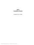
EST Catalog u EST3 Synergy
Card Reader
Controller
CRC, CRCXM
Overview
Standard Features
The Card Reader Controller (CRC) provides the power and electronics required to monitor and control a single door with both
entry and exit readers. The unit is designed to mount in close
proximity to the door it controls, however it can be located remotely from the readers in retrofit applications. The unit is housed
in an off-white Cycoloy® housing. Its attractive design allows for
surface mounting in exposed areas.
• Listed for fire, security, and access control
All access decisions are made locally in the CRC. The CRC’s nonvolatile memory can hold schedules and holiday information for up
to 8,000 cardholders. The CRCXM has additional memory, and
supports 36,000 cardholders. The memory also retains the last
5,000/20,000 events for logging purposes. This history information
is uploaded at the request of the access control database for use
in a variety of reports.
The unit provides 12 Vdc @ ½ amp for door strike or magnetic
lock requirements. An integral standby battery can provide up to
four hours of service for applications that use electric door strikes.
An integral tamper switch is also provided.
Two input circuits are provided for security devices. These are
typically used to monitor door position and request to exit devices. Input circuits can also be configured as a “buzz in” switch
to manually unlock the door, or as security input points when used
with Synergy-enabled EST3.
A handicapped feature output is provided to operate mechanical door openers with extended door-open times. This output is
activated when a cardholder with the disabled option activated
presents their card to the reader, helping provide barrier-free access.
Page 1 of 6
• Support of Wiegand output devices
— Proximity, Mag Stripe, etc.
• Total support for one door
• Two supervised device circuits
• Integral standby battery (optional)
• Supports maglock and strike operation
• PIN pad support and schedule
• Memory for 8,000/36,000 cardholders
• Self-contained operation
• Maintains all schedules and holidays
• No degraded mode needed
• Aesthetically pleasing design
• Integrates with EST3 and ACDB-KE systems
• Can initiate system activity
• Can respond to system activity
• Handicapped option facilitates barrier-free operation
• Construction card
• Optional sounder
• Can use existing cards and readers
85001-0528
D ATA S H E E T
Not to be used for installation purposes. Issue 6
Application
denied or irregular events.
Card Reader Controllers support Synergy-enabled EST3 control
platforms under EST’s Access Control Database (refer to Data
Sheet 85010-0098), and ACDB-KE standalone keyless entry systems under the ACDB-KE software program (refer to Data Sheet
85010-0132).
There is no degradation in system performance when both fire
and security devices are installed on the same network. The
CRC(XM) uses the same high quality components used in our fire
devices, and is UL-listed to fire (UL-864/ULC-S527), card access
(UL-294) and burglary (UL-609/ULC-S303) standards.
Credential Reader Support
The CRC(XM) is compatible with most credential readers such
as proximity and biometric devices having a standard Wiegand
output. Each CRC is capable of controlling both the ingress and
egress readers for a single door. Multiple readers for ingress and
egress are supported simply by parallelling the readers. This can
allow the use of multiple card types at a single door.
The Card Reader Controllers and Keypad Displays (KPDISP*) are
connected to the system over a supervised, dedicated RS-485
connection to the Security Access Control Module (3-SAC). Each
3-SAC can support up to 62 CRCs or KPDISPs. This is a multidrop circuit and does not require a home run for each device.
Should network communications be lost, the CRC will continue
to grant access based on the complete database stored in its
memory, without loss of any security feature, except possibly antipassback, two-man rule, and muster operations. For these type
of applications a Class A/Style 6 configuration can be installed.
In Class A the maximum number of devices on the 3-SAC is 30,
providing continued uninterrupted operation in the event of most
wiring faults.
CRCs provide support for a Construction Card. This feature facilitates system testing and an extra level of security until a database
is downloaded into the CRC. Once the CRC has a cardholder
database downloaded into it, the construction card automatically
becomes deactivated.
The CRC provides LED drivers to visually indicate whether access
is granted or denied. These generate different LED flash rates when
PIN numbers or a second card (two-man rule/escorted visitor) is required. A driver for an audible sounder is also provided by the CRC.
Access Levels, Schedules, and Holidays
An access level is a name assigned to a group of cardholders that
share common access privileges. These privileges consist of a
list of doors, each with a specified schedule. Any combination of
doors can be assigned to an access level. The CRC(XM) supports
1,200 different access levels (up to 255 per tenant, up to 255 per
ACDB-KE system), and each cardholder can belong to two access levels at the same time.
The CRC maintains in its memory all access levels, schedules
and holidays, created by the Access Control Database Program.
Each schedule identifies the specific time(s) (in 15-minute increments) and day(s) during which specific cardholders are permitted through a given door. The CRC(XM) can store up to 1,200
schedules (up to 255 per tenant) and 1,200 holidays (up to 255
per tenant).
Holidays are exceptions to normal Monday through Sunday
schedules, when different access requirements are desired. Many
holidays can be programmed using rules rather than fixed dates.
This minimizes year-to-year programming required to update
holidays annually. Fixed holidays, such as January 1st, that fall on
a Saturday or Sunday can automatically be scheduled for the closest Monday or Friday to coincide with statutory holidays.
Note: Not all CRC features described are supported by all compatible software.
Please refer to the software catalog sheets and manuals to determine functionality.
Synergy-Enabled Application
True integration permits system functions to interact seamlessly,
such as unlocking exit doors during a fire. A simple program rule
unlocks doors, replacing additional conduit, wiring and interposing
relays. Want to disarm security partitions automatically when an
authorized cardholder enters the building? Integration and another
system rule easily provides a solution.
Because each CRC makes its own access decisions, very little
network traffic is generated by the access control function. This,
along with the integrated design of the network operating system
ensures that fire signals always receive the highest priority. To reduce traffic even further, the CRC can be configured to report only
Page 2 of 6
Database Management
Each CRC(XM) contains the entire access control database within
its memory. This distribution of intelligence minimizes traffic on the
network, maximizing access decision speeds. Cardholder data is created and stored in the Access Control Database (ACDB) or ACDB-KE
software program that runs on any PC (see the ACDB catalog sheet
or ACDB-KE catalog sheet). This information is then encrypted and
sent to the CRCs by a hardwire or dial-up connection.
In a network environment, the PC is simply equipped with a conventional modem. The ACDB program then dials up the network
and sends the encrypted database information via the network
to the individual CRCs. This allows a ACDB to serve multiple sites.
Dial-up data entry also permits multiple tenants to share a common
access control system without sharing a common database. PCs
may also be directly connected to the system using a direct serial
connection.
* See KPDISP literature for a full description of the functionality offered by the keypad display
Networked Applications
Access controlled doors can be grouped into one of 255 partitions. Partitions are used to define the protection for a given area.
This facilitates arming and disarming of security alarms, as well as
anti-passback, two-man rule, and muster operation. Each CRC
can support one partition.
As part of an integrated system, CRCs can be programmed to automatically bypass alarm points, eliminating one of the most common causes of false alarms. Integration also permits the system to
be programmed to automate routine functions such as turning on
lights and adjusting room temperature.
Up to 255 tenants are supported by the CRC. During system
installation, the available schedules and holidays are allocated to
each one. The use of individual access control database programs
and dial-up modem connections simplifies the addition of a new
tenants or the reconfiguring of existing ones.
Doors located at remote sites are supported using dial-up modem
connections. No local dedicated PC or computer wiring is required
for database transactions.
Elevator floor access control is accomplished using the CRC and
the EST3 integrated system. Because the fire portion of the system is already interconnected with the elevator controller for elevator capture functions, floor access control is a simple extension of
this pre-existing function.
85001-0528
D ATA S H E E T
Not to be used for installation purposes. Issue 6
The CRC(XM) is listed to UL-864, the fire alarm standard, to UL294, the access control system unit standard, and to UL-609/
ULC-S303 burglar alarm standards. This raises the level of the
access control components up to the high standards of fire alarm
equipment and permits fire, security, and access control functions
to be fully integrated while assuring all listing and code requirements are met.
The CRC’s flexibility supports three different versions of anti–
passback: strict, timed, and logged. Strict anti-passback requires
the use of an exit reader and will not permit reuse of a card until
it has been used to exit the area. In order to eliminate the need
for an exit reader, the timed anti-passback mode prohibits the
reuse of the card for a predetermined time period. This virtually
eliminates users passing a card back to a second user, this is the
origin of the anti-passback feature. The logged anti-passback
mode permits access, but logs any violation to history for future
employee counselling.
When an area is served by more than one door, a networked
system is required to provide support for two-man rule operation,
muster operation, and strict anti-passback. The network coordinates user information between CRCs that serve a common area.
ACDB-KE Keyless Entry Applications
The CRC provides effective support for standalone applications in
conjuction with EST’s ACDB-KE keyless entry software package.
ACDB-KE can accommodate up to 31 doors. It offers many of
the standard access control features found in the ACDB including cardholder-specific access privileges, multiple access levels,
customizable schedules, and holiday rules.
ACDB-KE offers no security functions. However, CRC Form-C
relays can be configured to trigger external door openers, or they
can be programmed to interface with third-party security systems.
To achieve security functionality, the relay can be set to change
state if no rex, valid card read, or unlock timer is in effect when the
door is opened. When connected to a security system, this allows
the use of the door position contact as a security input.
ACDB-KE communicates with the CRC via hard-wired RS-232 to
RS485 converters.
Database Management
ACDB-KE standalone keyless entry systems communicate with
CRCs via hardwired RS-232 to RS-485 converters.
Engineering Specification
Synergy Enabled Applications
The Card Reader Controller (CRC) shall provide the power and
electronics required to monitor and control a single door, both
entry and exit readers; all necessary support for request to exit
devices, automatic door openers, and locking mechanisms. All
access decisions shall be made by the CRC. Decisions made by
a centralized controller shall not be considered as equal. Each
CRC shall maintain all schedules and holiday schedules for up to
<8,000><36,000> cardholders. Upon loss of communication with
the security/access control module, the CRC default mode shall
provide 100% functionality utilizing all schedules and holiday data
stored in its memory, and shall not grant access solely by matching facility codes. Each controller shall retain <5,000><20,000>
history events in its memory. History events shall be uploaded
to the access control database program under manual and/or
automatic control.
The CRC shall be capable of connecting to any credential reader that
Page 3 of 6
uses the standard Wiegand output protocol format, and shall support PIN# input through a keypad (using 8-bit Dorado format) that is
integral to the reader. It shall be possible to program a PIN schedule
such that a PIN number is only required at specific times (eg. weekends and evenings) to gain access and <is><is not> required during
regular business hours. The controller shall provide two configurable
supervised input circuits for use as request to exit devices, security
inputs, or manual “buzz in” control. The controller shall provide a set
of form “C” relay contacts to activate an automatic door opener when
a valid card with the handicapped option enabled is presented to the
reader. Other relay functions shall be programmable
The CRC shall be housed in an attractive enclosure suitable for
surface mounting near the door without detracting from interior
aesthetics. Power for the CRC shall be <16VAC provided by a local
class 2 plug-in transformer> <24 VDC supplied by the integrated
network> <The controller shall be equipped with a standby battery and integral charger, to minimize the effects of a loss of power.
The battery shall be capable of operating a lock strike for up to four
hours.> The controller shall provide 12 VDC @ ½ amp to operate
the door locking mechanism. The lock control voltage shall be configurable as either energize to access or de-energize to access.
As a multi-function component of a truly integrated system, the
card reader controller shall be listed according to Underwriter’s
Laboratory Standards: <UL-294 Access Control System Units,
UL-864 Control Units for Fire-Protective Signaling Systems,
and UL-1610 Central-Station Burglar-Alarm Units><ULC-S527,
UL-294, ULC-S301>. Controllers not having all of the specified
agency listings will not be considered as equal.
The card reader controller shall be a Edwards model <CRC (8,000
cardholder)><CRCXM (36,000cardholder)>.
ACDB-KE Applications
The Card Reader Controller (CRC) shall provide the power and
electronics required to monitor and control a single door, both
entry and exit readers; all necessary support for request to exit
devices, automatic door openers, and locking mechanisms. All
access decisions shall be made by the CRC. Each CRC shall
maintain all schedules and holiday schedules for up to 8,000
cardholders.
The CRC shall be capable of connecting to any credential reader
that uses the standard Wiegand output protocol format, and shall
support PIN# input through a keypad (using 8-bit Dorado format)
that is integral to the reader. It shall be possible to program a PIN
schedule such that a PIN number is only required at specific times
(eg. weekends and evenings) to gain access and <is><is not>
required during regular business hours. The controller shall provide
two configurable supervised input circuits for use as request to exit
devices, security inputs, or manual “buzz in” control. The controller
shall provide a set of form “C” relay contacts to activate an automatic
door opener when a valid card with the handicapped option enabled
is presented to the reader. Other functions shall be programmable
The CRC shall be housed in an attractive enclosure suitable for
surface mounting near the door without detracting from interior
aesthetics. Power for the CRC shall be <16VAC provided by a local
class 2 plug-in transformer> <24 VDC supplied by the listed power
supply> <The controller shall be equipped with a standby battery
and integral charger, to minimize the effects of a loss of power. The
battery shall be capable of operating a lock strike for up to four
hours.> The controller shall provide 12 VDC @ ½ amp to operate
the door locking mechanism. The lock control voltage shall be configurable as either energize to access or de-energize to access.
The card reader controller shall be a Edwards model CRC.
85001-0528
D ATA S H E E T
Not to be used for installation purposes. Issue 6
16.5 Vac IN
2
16.5 Vac IN
1
To next CRC or
other device
5
From AC/Load terminals
on plug-in transformer (CRCXF)
Note: The ground terminal on the
transformer is not used.
2 twisted pair
(24 Vdc and
3-SAC bus)
- SAC bus OUT
Loop GND
Loop 1 IN
Loop 2 IN
To next device or 120 EOL
if this is the last device on
Class B or back to 3-SAC
module if Class A.
From power supply
EST 3
+ SAC bus OUT
From control panel
or previous device
4
EDWARDS SYSTEMS TECHNOLOGY
- SAC bus IN
47 K 47 K
EOL EOL
From strike/maglock/
access relay
Accessory
relay
mounting
space
Sounder
Data 1
Security Access
Control Bus
Dry contact
connections
TB-2
+ SAC bus IN
10 11 12 13 14 15 16 17 18 19 20 21 22 23
RED LED
9
GREEN LED
8
Data 0
Reader PWR
7
Reader GND
6
C
5
NC
NO
4
Strike PWR
3
Strike GND
2
-24 V IN
1
-24 V OUT
TB-1
J1
+24 V IN
Synergy Enabled Applications
+24 V OUT
Typical Wiring
S1
Tamper switch. Engaged when
the cover is installed and activates
when the cover is removed.
Red (+)
To battery
Black (-)
Reader wire connections
CRC terminal block numbers (designators)
Reader
manufacturers
CRC
EST / HID 3
Motorola Indala 3
2 twisted pair
(24 Vdc and
3-SAC bus)
CRC
10
(Reader
power)
11
(Reader
GND)
13
(Data 1)
1
12
(Data 0)
1
14
RED LED
15
GREEN
LED
16
(Sounder)
2
Red
Black
Green
White
Brown
Orange
Yellow
Red
Black
Green
White
Brown
---
Blue
Dorado
Red
Black
Green
White
Brown
---
Yellow
Sensor Eng.
Red
Black
Green
White
Violet
Brown
Blue
Keri
Red
Black
Green
White
Brown
Orange
Blue
Radio Key 3
Paradox/Position
Technology
Red
Black
Green
White
Brown
Orange
Blue
Red
Black
Green
White
Orange
Yellow
Brown
Notes:
Jumper Setup
2 twisted pair
(24 Vdc and
3-SAC bus)
To next CRC
or KPDISP
6
CRC
24 Vdc
+ CRC 24 Vdc
+
-
CRC
24 Vdc
+ CRC 24 Vdc
+
-
6
Additional
Power Supply
24 Vdc
Additional
+ Supply
Power
24 Vdc
+ -
6
If used as an inside reader, connect the green wire to TB113 and the white wire to TB1-12.
Continuous power
(using maglock or
continuously powered strike)
2
Connect wiring only when using the reader's sounder.
JP1 1
2
3
Output source
3
Program for dual-LED control.
JP2
2
3
Input source
4
Use a 4.7 K, 1/4 watt resistor if no strike is being used to
maintain supervision.
DC power
(from panel)
5
When maglock or door strike voltage or current is outside
CRC(XM) operational parameters, use an accessory relay
(catalog number CRCRL) and a listed external power supply
to power the lock. Refer to the accessory relay's installation
sheet (3100294) for more information.
6
Minus common from control panel must be maintained
AC power
(from transformer)
Control Panel
Control Panel
Power
supply
24
Vdc
Power
+ supply
24 Vdc
+ -
Intermitant power
(using strike)
1
CRC
24 Vdc
+ CRC 24 Vdc
+
-
6
1
Typical Wiring
ACDB-KE Applications
ACDB-KE
RS232 or USB
Communications
Control Panel
Control Panel
Power
supply
24
Vdc
Power
+ supply
24 Vdc
+ -
6
6
Page 4 of 6
CRC
24 Vdc
+ CRC 24 Vdc
+
-
CRC
24 Vdc
+ CRC 24 Vdc
+
-
See note 1
Converter
232/485
USB/485
CRCXF
Transformer
CRCXF
+ Transformer
+ -
6
CRC
24 Vdc
+ CRC 24 Vdc
+
-
See note 1
Ditek
Surge Protector
Model
DTK-2LVLP-D
See note 1
CRC
CRC
AC (CRCXF)
transformer
AC (CRCXF)
transformer
To next
CRC
Note 1: Three wires = 1 common, 1 twisted pair RS-485 with 6 twists per ft. min.
See literature sheet 85010-0132 for additional ACDB-KE drawings
6
85001-0528
D ATA S H E E T
Not to be used for installation purposes. Issue 6
Specifications
Agency Listings
Door Capacity
Credential Reader Compatibility
Keypad Compatibility
Input Circuits
UL, ULC (See Note 1)
Each CRC(XM) serves one door - one ingress reader/keypad, one egress reader/keypad, one lock mechanism, and
required request to exit devices.
Any Wiegand output device including proximity, magnetic stripe, Wiegand, Barium Ferrite, & biometric readers with
Wiegand outputs.
Any reader with integral keypad using the Dorado® 8-bit keypad format.
Two supervised. Configurable for request to exit button/PIR motion detector, security input, or “buzz in” switch.
Network programmable bypass, arm/disarm
Lock Control
Power
Lock Types supported
Supervision
Delay
Reader Power
Cardholder Capacity
Schedules & Holidays
Anti-Passback
2-Man Rule
Partitions
Muster operation
Event Memory
Network Communications
Keyless Entry Communications
ACDB-KE computer to CRCs
Local Sounder (CRCSND)
Form C Relay
Supervision
Input Circuits
Tamper
AC Fail
Low Battery
Strike
Reader
CPU/Memory
Network Communications
Internal Clock
Power Requirements from 24
Vdc source
CRC(XM) Transformer Powered
Wire Size
Standby Battery (optional)
Operating Environment
Housing
Dimensions (HWD)
Mounting
12 Vdc @ 0.5A, max
Configurable for continuous (mag-lock) or pulse (strike) operation
Strikes are supervised for presence
Programmable exit delay
12 Vdc @ 0.5A, max.
CRC = 8,000; CRCXM = 36,000
1,200 schedules and 1,200 holidays. Each tenant in an integrated system, or each ACDB-KE system, can be
assigned up to 255 schedules and 255 holidays.
Networked = 62 doors per partition on the same 3-SAC
Networked = 62 doors per partition on the same 3-SAC
Networked = 255
61 doors per partition on the same 3-SAC
CRC = 5,000 events, CRCXM = 20,000 events; configurable for all, denied, or irregular events
RS-485, Class A or Class B 4,000ft (1,220m) maximum circuit length (3-SAC)
RS-232 to RS-485: Use B&B Electronics Model 485CSP2 or equivalent (Note: Port powered RS-232 to 485
converters are not recommended. Always use converters with external power supplies.) USB to RS-485: Use B&B
Electronics Model USTL4 or equivalent TCP/IP to RS-485: Use Edwards NETCOM-1S
Optional piezo sounder configurable for door ajar and unauthorized entry/exit - 12 Vdc @ 7mA
Contact (30 Vdc/ac @ 2A, resistive) to operate system auxiliary functions including automatic door openers
Class B monitored for opens, shorts & normal conditions
Cover monitored for normal & open conditions
Monitored for loss of AC power
Monitored for low battery voltage during primary power loss
Monitored for open & normal conditions when door is locked
Monitored for open and normal conditions
Monitored for internal failures, erase or write failures
Monitored by the network
24 hour clock. Automatically synchronized on networks
310 mA + (Lock current @ 12 Vdc) + (Reader Current @ 12 Vdc) + (CRCSND current, if used).
Max. AC power will not exceed 40 VA @ 120 Vac
14 to 22 AWG (1.5 mm² to 0.25mm²) See Note 2.
12V @1.2AH (approximately 4 hours standby w/strike - standby time may vary depending on door traffic)
0°C to 49° Complete (32°F to 120°F) @ 93%RH, Non-condensing
Off-white Cycoloy® Thermoplastic
4.75” x 8.0” x 2.5” (12.0cm x 20.5cm x 6.4cm)
Surface mount. Optional 4” square or 2-gang or 100mm² electrical box
Note 1:
The EST3 is modularly listed under the following standards:
UL 864 categories: UOJZ, UOXX, UUKL and SYZV, UL 294 category ALVY, UL 609 category AOTX, UL 636 category ANET, UL 1076 category APOU, UL
365 category APAW, UL 1610 category AMCX, UL 1635 category AMCX ULC-S527, ULC-S301, ULC-S302, ULC-S303, ULC-S306, ULC/ORD-C1076,
ULC/ORD-C693. Please refer to EST3 Installation and Service Manual for complete system requirements.
Note 2:
When wiring between CRCs is installed outside as between two buildings, surge protection is needed on the CRC wires leaving and entering the building.
Use Ditek’s Surge Protector Model 2LVLP.
Page 5 of 6
85001-0528
D ATA S H E E T
Not to be used for installation purposes. Issue 6
Ordering Information
Catalog Number
CRC
Detection & alarm since 1872
U.S.
T 888-378-2329
F 866-503-3996
Canada
Chubb Edwards
T 519 376 2430
F 519 376 7258
CRCXM
CRCSND
12V1A2
CRCXF
CRCRL
Description
Card Access Controller
w/memory for 8,000 cardholders
Card Access Controller
w/memory for 36,000 cardholders
CRC Sounder Module
12V @1.2AH Standby Battery
Class 2, 120 Vac Input/16 Vac Output.
Plug in Transformer 40VA
Access Control Accessory Relay 12 Vdc 34mA coil,
N/O contact, rated at 2 amps @ 30 Vdc .6PF, 2
amps @ 120/250 Vac .6PF.
Shipping Wt., lb (kg)
1.5 (0.68)
1.5 (0.68)
0.25 (0.11)
1.75 (0.79)
2.0 (0.91)
0.25 (0.11)
Southeast Asia
T : +65 6391 9300
F : +65 6391 9306
India
T : +91 80 4344 2000
F : +91 80 4344 2050
Australia
T +61 3 9239 1200
F +61 3 9239 1299
Europe
T +32 2 725 11 20
F +32 2 721 86 13
Latin America
T 305 593 4301
F 305 593 4300
utcfireandsecurity.com
© 2010 UTC Fire & Security.
All rights reserved.
85001-0528
D ATA S H E E T
Not to be used for installation purposes. Issue 6
05-18-11
Page 6 of 6