1
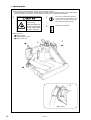
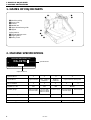
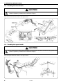
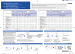
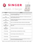
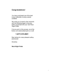
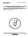
DA-9270
INSTRUCTION MANUAL
Please read this manual before using the machine.
Please keep this manual within easy reach for quick reference.
TWIN NEEDLE (THREE NEEDLE) FEED OFF THE ARM
DOUBLE CHAIN STITCHER
Thank you very much for buying a BROTHER sewing machine. Before using your new machine, please
read the safety instructions below and the explanations given in the instruction manual.
With industrial sewing machines, it is normal to carry out work while positioned directly in front of moving
parts such as the needle and thread take-up lever, and consequently there is always a danger of injury that
can be caused by these parts. Follow the instructions from training personnel and instructors regarding
safe and correct operation before operating the machine so that you will know how to use it correctly.
SAFETY INSTRUCTIONS
z Safety indications and their meanings
This instruction manual and the indications and symbols that are used on the machine itself are provided
in order to ensure safe operation of this machine and to prevent accidents and injury to yourself or other
people.
The meanings of these indications and symbols are given below.
Indications
CAUTION
The instructions which follow this term indicate situations where failure to
follow the instructions could cause injury when using the machine or physical damage to equipment and surroundings.
Symbols
................ This symbol (
) indicates something that you should be careful of. The picture inside the triangle indicates the nature of the caution that must be taken.
(For example, the symbol at left means “beware of injury”.)
................ This symbol (
) indicates something that you must not do.
................ This symbol (
) indicates something that you must do. The picture inside the circle
indicates the nature of the thing that must be done.
(For example, the symbol at left means “you must make the ground connection”.)
x Notes on safety
CAUTION
Installation
¡ Machine installation should only be carried out by a qualified technician.
¡ Contact your Brother dealer or a qualified electrician for any electrical work
that may need to be done.
¡ The sewing machine weighs more than
49 kg. The installation should be carried
out by two or more people.
¡ Do not connect the power cord until installation is complete, otherwise the
machine may operate if the treadle is
pressed by mistake, which could result
in injury.
¡ Be sure to connect the ground. If the
ground connection is not secure, you run
the risk of receiving a serious electric
shock.
i
DA-9270
¡ All cords should be secured at least 25
mm away from any moving parts. Furthermore, do not excessively bend the
cords or secure them too firmly with
staples, otherwise there is the danger
that fire or electric shocks could occur.
¡ Install the belt covers to the machine
head and motor.
¡ If using a work table which has casters,
the casters should be secured in such a
way so that they cannot move.
¡ Be sure to wear protective goggles and
gloves when handling the lubricating oil,
so that no oil gets into your eyes or onto
your skin, otherwise inflammation can
result.
Furthermore, do not drink the oil under
any circumstances, as it can cause vomiting and diarrhoea.
Keep the oil out of the reach of children.
CAUTION
Sewing
¡ This sewing machine should only be
¡ Turn off the power switch at the follow-
used by operators who have received
the necessary training in safe use beforehand.
ing times, the machine may operate if
the treadle is pressed by mistake, which
could result in injury.
¡ When threading the needle
¡ When replacing the needle
¡ When not using the machine and
when leaving the machine unattended
¡ The sewing machine should not be used
for any applications other than sewing.
¡ Attach all safety devices before using the
¡ If using a work table which has casters,
sewing machine. If the machine is used
without these devices attached, injury
may result.
the casters should be secured in such a
way so that they cannot move.
¡ Do not touch any of the moving parts or
press any objects against the machine
while sewing, as this may result in personal injury or damage to the machine.
¡ If an error occurs in machine, or if abnormal noises or smells are noticed, immediately turn off the power switch. Then
contact your nearest Brother dealer or a
qualified technician.
¡ If the machine develops a problem, contact your nearest Brother dealer or a
qualified technician.
Cleaning
¡ Turn off the power switch before carry-
¡ Be sure to wear protective goggles and
ing out cleaning. The motor will keep
turning even after the power is switched
off as a result of the motor’s inertia. Wait
until the motor stops fully before starting work.
The machine may operate if the treadle
is pressed by mistake, which could result
in injury.
gloves when handling the lubricating oil,
so that no oil gets into your eyes or onto
your skin, otherwise inflammation can
result.
Furthermore, do not drink the oil under
any circumstances, as it can cause vomiting and diarrhoea.
Keep the oil out of the reach of children.
Maintenance and inspection
¡ Maintenance and inspection of the sew-
¡ If the power switch needs to be left on
ing machine should only be carried out
by a qualified technician.
when carrying out some adjustment, be
extremely careful to observe all safety
precautions.
¡ Ask your Brother dealer or a qualified
electrician to carry out any maintenance
and inspection of the electrical system.
¡ Turn off the power switch and disconnect the power cord from the wall outlet at the following times, otherwise the
machine may operate if the treadle is
pressed by mistake, which could result
in injury.
However, the motor will keep turning
even after the power is switched off as
a result of the motor’s inertia. Wait until
the motor stops fully before starting
work.
¡ Use only the proper replacement parts
as specified by Brother.
¡ If any safety devices have been removed, be absolutely sure to re-install
them to their original positions and
check that they operate correctly before
using the machine.
¡ Any problems in machine operation
which result from unauthorized modifications to the machine will not be covered by the warranty.
¡ When carrying out inspection, adjust-
ment and maintenance
¡ When replacing consumable parts
such as the looper
DA-9270
ii
c Warning labels
★ The following warning labels appear on the sewing machine.
Please follow the instructions on the labels at all times when using the machine. If the labels have
been removed or are difficult to read, please contact your nearest Brother dealer.
1
2
Be sure to connect the ground.
If the ground connection is not
secure, you run the risk of receiving a serious electric shock.
3
Direction of operation
Moving parts
may cause injury.
Operate with safety devices.
Turn off main switch before
threading, changing bobbin
and needle, cleaning etc.
Safety devices
q Finger guard
w Thread take-up cover
e Pulley cover, etc.
w
3
1
e
q
2
<Rear view>
iii
DA-9270
CONTENTS
1. NAMES OF MAJOR PARTS ...................... 01
9. STANDARD ADJUSTMENTS ................... 15
9-1.
9-2.
Needle bar height adjustment ...........
Needle and looper timing
adjustment ............................................
9-3. Timing of loopers running clear of
needles ..................................................
9-4. Needle guard adjustment ...................
9-5. Feed dog height adjustment ..............
9-6. Upper thread take-up thread
guide adjustment .................................
9-7. Upper thread arm thread guide
adjustment ............................................
9-8. Thread release shaft adjustment .......
9-9. Lower thread take-up timing
adjustment ............................................
9-10. Installing the lapper .............................
9-11. Puller height adjustment
(Machines with puller) ........................
9-12. Puller device timing adjustment
(Machines with puller) ........................
2. MACHINE SPECIFICATIONS ..................... 01
3. WORK TABLE AND MOTOR .................... 02
4. INSTALLATION ............................................. 03
4-1.
4-2.
4-3.
4-4.
4-5.
4-6.
4-7.
Installing the machine head ...............
Ground wire connections ...................
Installing the pulley cover ..................
Belt tension adjustment ......................
Cotton stand .........................................
Lubrication ............................................
Checking the machine pulley
rotating direction .................................
03
04
05
06
06
07
08
5. PREPARATION BEFORE SEWING ........... 08
5-1.
5-2.
5-3.
5-4.
Needles and threads ............................
Installing the needles ..........................
Threading the lower threads ..............
Threading the upper threads .............
08
08
09
09
6. SEWING ......................................................... 10
6-1.
15
16
17
17
18
19
19
19
19
20
20
20
10.TROUBLESHOOTING ................................. 21
Sewing .................................................. 10
7. THREAD TENSION ...................................... 11
7-1.
7-2.
7-3.
7-4.
Adjusting the thread tension .............
Presser foot pressure adjustment .....
Adjusting the stitch length .................
Puller feed adjustment (Machines
with puller) ...........................................
11
11
12
12
8. CLEANING ..................................................... 14
8-1.
8-2.
Daily cleaning ....................................... 14
Changing the lubricating oil
(every three months) ........................... 14
DA-9270
iv
1. NAMES OF MAJOR PARTS
2. MACHINE SPECIFICATIONS
1. NAMES OF MAJOR PARTS
u
q
t
o
q Machine pulley
w Front cover
e Presser
r Needle bar
t Upper thread arm guide
y Lapper
r
Safety device
u Thread take-up cover
i Finger guard
o Pulley cover
e
i
y
w
2. MACHINE SPECIFICATIONS
BROTHER INDUSTRIES, LTD.
DA-9270-1
Specifications
MADE IN JAPAN
Optional device
Specifications
-1
-2
-3
-A
Light materials
Light - medium
materials
Medium
materials
Light materials, with puller
No. of needles
2
2
2
Needle TV X 64
#12
#14
#16
4.8 mm (3/16)
6.4 mm (1/4)
3.2 mm (1/8)
4.0 mm (5/32)
4.8 mm (3/16)
6.4 mm (1/4)
Applications
Needle gauge
Max. stitch length
3.0 mm
3.5 mm
Min. arm size
Max. sewing speed
1
2
3
#11PSU
4.8 mm (3/16)
6.4 mm (1/4)
6.4 mm (1/4)
3.0 mm
171 mm
4,000 rpm
DA-9270
3,600 rpm
3. WORK TABLE AND MOTOR
3. WORK TABLE AND MOTOR
■ Work Table
If using a commercially-available table
¡ The top of the table should be 40 mm in thickness and should be strong enough to hold the weight and withstand the vibration of the sewing machine.
¡ Drill holes as indicated in the illustration below.
A
Chain hole
C
B
Motor mounting holes
D
C
Cotton stand hole
A
Depth 1 +0.5
0
D
Ground hole
B
■ Motor
CAUTION
¡ All cords which are connected to the motor
¡ Install the correct belt cover which corresponds
should be secured at least 25 mm away from
any moving parts. Furthermore, do not excessively bend the cords or secure them too firmly
with staples, otherwise there is the danger that
fire or electric shocks could occur.
to the motor being used.
<Motor>
¡ Select the correct motor from those listed in the above table.
¡ Refer to the instruction manual for the motor for details on installing and using the motor.
Power
Motor
Single-phase
2-pole, 400 W motor
Three-phase
2-pole, 400 W motor
<Motor pulley and V-belt>
¡ Refer to the table below to select the motor pulley and belt combination.
¡ The belt should be an M-type V-belt.
Pulley O.D.
65
75
80
85
90
95
100
...
../
..
.M42
M43.../
,.....
......
M44.../
,.....
....
Belt size (inches)
Sewing speed (rpm)
70
50Hz
60Hz 3100
3100
3600
3600
4000
4000
DA-9270
2
4. INSTALLATION
4. INSTALLATION
CAUTION
¡ The sewing machine should only be installed
¡ Do not connect the power cord until installation
by a qualified technician.
¡ Ask your Brother dealer or a qualified electri-
is complete, otherwise the machine will operate if the treadle is pressed by mistake, which
could result in injury.
cian for any electrical work that may need to
be done.
¡ Be sure to connect the ground. If the ground
¡ The sewing machine weighs more than 49 kg.
connection is not secure, serious electric shocks
will result.
The installation should be carried out by two
or more people.
¡ Install the pulley cover to the machine head.
4-1. Installing the machine head
1. Install pulley cover base w on machine bed q with two
hexagonal bolts e and two washers r.
2. Insert two bar cushions t into the holes in the bottom
of the bed.
t
r
e
q
w
(Bottom view)
* At this time, install the two hexagonal bolts e so that
they go as far as possible into the notches in the
pulley cover base w.
Furthermore, check that the pulley cover base w is
parallel to the bed. (If it is not parallel, the pulley
cover may touch the machine pulley.)
Parallel
q
w
r
e
w
3
DA-9270
4. INSTALLATION
u
!0
y
3. Place the machine head on the table, adjust its position in forward and backward directions by aligning it
with the hole for presser bar lifter chain y, and in sidewise directions by aligning it with belt hole !0.
u
4. After fastening cushions u to the machine bed and
pulley cover base with set screws i, fix them to the
table with screws o.
* Place the work table so that the machine head is
horizontal.
If the machine head is not horizontal, lubrication will
not be carried out correctly.
i
u
o
5. Connect the presser bar lifter chain y to the knee lifter
lever !1 and the presser lifter pedal !2.
!1
y
!2
4-2. Ground wire connections
r
q
e
w
To motor
Connect the ground wire to the sewing machine head and
motor.
(Use the correct type of ground wire and washer.)
1. Remove lower thread guide holder screw w.
2. Secure the ground wire q to the sewing machine head
with screw w and washer e.
(The attachment location is indicated by a ground symbol r.)
3. Pass the ground wire q through the hole in the table.
4. Connect the ground wire q to the motor in accordance
with the instructions in the instruction manual for the
motor.
DA-9270
4
4. INSTALLATION
4-3. Installing the pulley cover
1. Place the belt w onto the machine pulley q.
* Pull the belt w upward when installing pulley cover
A e.
w
q
2. Place pulley cover A e so that it is in between the eight
pulley cover seats t, and then secure it to the pulley
cover base with the four screws r.
r
t
e
t
3. Push the belt w downward, and then install pulley
cover B y to pulley cover A e with the three screws
u.
y
u
e
w
4. If the machine is being used with the puller attached,
install the puller belt cover i with the two screws o.
o
i
5
DA-9270
4. INSTALLATION
4-4. Belt tension adjustment
1. Place the V-belt e onto the motor pulley w.
2. Turn the two nuts r to adjust so that there is 20 - 30
mm of deflection in the V-belt e when it is pressed at
the midway point with a force of 9.8 N.
q
20 - 30mm
r
e
w
4-5. Cotton stand
1. Assemble the cotton stand while referring to the cotton stand instruction manual.
2. Install the cotton stand to the cotton stand mounting
hole in the work table with the nut q.
q
DA-9270
6
4. INSTALLATION
4-6. Lubrication
CAUTION
¡ Be sure to wear protective goggles and gloves when handling the lubricating oil, so that no oil gets into
your eyes or onto your skin, otherwise inflammation can result.
Furthermore, do not drink the oil under any circumstances, as it can cause vomiting and diarrhoea.
Keep the oil out of the reach of children.
¡ The sewing machine should always be lubricated and
r
the oil supply replenished before it is used for the first
time, and also after long periods of non-use.
y
★ Use only the lubricating oil (Nisseki Mitsubishi Sewing
Lube 15N; VG15) specified by Brother.
t
Upper
reference
line
q
e
w
1. Open the front cover q, remove the rubber plug w, and
then fill with oil until the oil level reaches the point in
between the reference lines on the oil gauge e.
* If the oil level drops to the lower reference line, be
sure to add more oil.
2. Insert the rubber plug w and then close the front cover
q.
3. Add 1 - 2 drops of oil once a week to needle bar bracket
lubrication hole r.
4. Periodically loosen the oil drain screw t to drain out
any oil which collects in the front bed oil sump. After
draining the oil, tighten the oil drain screw t.
5. Periodically wipe away any oil which collects in the rear
bed oil sump y with a cloth.
Lower reference line
6. Turn the machine pulley, so that the oil hole cover u
is facing upward, and then remove the oil hole cover
u and fill the oil tank i with oil.
If the level of lubricating oil drops below the middle reference line o on the oil tank, no oil will be drawn into
the upper shaft, and the upper shaft will thus not be
lubricated sufficiently. Be sure to maintain the lubricating oil level at a level above the center reference line.
7. Attach the oil hole cover u.
u
i
o
* If the machine is being used with the puller attached,
remove the cover screws !1 and fill with oil until the
level reaches the upper reference line in the oil sight
glass.
* If the oil level drops to the lower reference line, be
sure to add more oil.
After lubrication is completed, tighten the cover
screws !1.
!1
Upper
reference
line
Lower
reference
line
7
DA-9270
4. INSTALLATION
5. PREPARATION BEFORE SEWING
4-7. Checking the machine pulley rotating direction
CAUTION
¡ Do not touch any of the moving parts or place any objects against the machine while sewing, as this may
result in personal injury or damage to the machine.
1. Insert the power cord plug into the wall outlet, and
then turn on the power switch.
2. Depress the treadle slightly and check that the machine pulley starts to turn in the direction of the arrow q.
* If the direction of rotation is reversed, change the
direction of rotation to the correct direction while
referring to the instruction manual for the motor.
* For the first 3 - 4 days of use, run the machine at
500 rpm lower than the usual speed. This will help
contribute to a longer service life for the machine.
q
5. PREPARATION BEFORE SEWING
5-1. Needles and threads
The needle and threads to be used vary depending on sewing conditions. Select the correct ones by referring to the
table below.
Thread
Needle
Upper thread
Lower thread
ORGAN TV×64
#11
#12
spun yarn #80
spun yarn #80
#14
spun yarn #60
spun yarn #60
#16
spun yarn #50
spun yarn #50
5-2. Installing the needles
CAUTION
¡ Turn off the power switch before installing the needle, otherwise the machine may operate if the treadle is
pressed by mistake, which could result in injury.
q
w
1. Turn the pulley until needle holder q is raised to the
highest position.
2. Loosen needle set screws w, hold needles e with their
long grooved side facing front, insert them into needle
holder q all the way, and fasten the needle with needle
set screws w.
e
DA-9270
8
5. PREPARATION BEFORE SEWING
5-3. Threading the lower threads
CAUTION
¡ Turn off the power switch before threading the upper thread, otherwise the machine may operate if the
treadle is pressed by mistake, which could result in injury.
Pass the lower threads as shown in the figure below.
12
2
Needle hole
position
3
3
2
3
(1)
1
(3)
50 - 60mm
1
Needle hole
position
1
2
1 2
3
3
1
2
3
5-4. Threading the upper threads
CAUTION
¡ Turn off the power switch before threading the upper thread, otherwise the machine may operate if the
treadle is pressed by mistake, which could result in injury.
Pass the upper threads as shown in the figure below.
4
5
6
4
5
6
1
2
6
3
5
4
5
4
1 2
6
3
50 - 60mm
6
1
5
4
6
4
9
DA-9270
5
2
3
6. SEWING
6. SEWING
CAUTION
¡ Attach all safety devices before using the sewing machine. If the machine is used without these devices
attached, injury may result.
¡ Turn off the power switch at the following times, otherwise the machine may operate if the treadle is pressed
by mistake, which could result in injury.
¡ When threading the needle
¡ When replacing the needle
¡ When not using the machine and when leaving the machine unattended
¡ Do not touch any of the moving parts or place any objects against the machine while sewing, as this may
result in personal injury or damage to the machine.
6-1. Sewing
1. Switch the power on.
2. Depress presser lifter pedal q and place the work under the presser foot.
3. Release the presser lifter pedal.
4. The machine starts running when treadle w is stepped
down.
q
w
e
5. After sewing the work, move the work to thread cutter
e to make blank stitches, and cut the thread with it.
DA-9270
10
7. THREAD TENSION
7. THREAD TENSION
7-1. Adjusting the thread tension
Upper thread
Good stitches
Lower thread
Lower thread
Upper thread
Loose, bad stitches
Appearance of seam when upper thread
tension is too weak
q
Becomes
weaker
Becomes
stronger
1. Adjust the upper thread tension properly by turning upper thread adjusting screw q.
2. Adjust the lower thread tension properly by turning
lower thread adjusting screw w.
w
Becomes stronger
Becomes weaker
7-2. Presser foot pressure adjustment
Becomes Becomes
weaker stronger
q
Becomes
stronger
Becomes
weaker
w
11
Adjust the presser foot pressure by turning presser adjusting screw q so that the pressure is just enough to feed the
work positively and keep the work from slipping.
* In case of Machines with puller the puller pressure can
be adjusted as appropriate to the work by turning
presser adjusting screw w.
DA-9270
7. THREAD TENSION
7-3. Adjusting the stitch length
CAUTION
¡ Turn off the power supply before adjusting the stitch length, otherwise the machine will operate if the treadle
is pressed by mistake, which could result in injury.
However, the motor will keep turning even after the power is switched off as a result of the motor’s inertia.
Wait until the motor stops fully before starting work.
¡ The numerals on the machine pulley scale represent the
stitch length (mm), however the actual stitch length will
vary depending on the type and thickness of material being used.
w
1. Open the front cover e.
2. While pressing the feed adjustment button q, turn the
machine pulley toward you slowly. (The feed adjustment button q will move further inward.)
3. While still pressing the feed adjustment button q, keep
turning the machine pulley until the desired numeral
appears in the center of the pulley cover windows w.
* The higher the value of the numeral, the larger the
stitch length becomes.
Release the feed adjustment button q.
(Check that the feed adjustment button q pops back
out again.)
4. Close the front cover e.
NOTE:
Do not press the feed adjustment button q while the
machine is operating, as doing so may damage the
machine parts.
When sewing with the stitch length set close to the
maximum length, you will need to adjust the needle
guard in accordance with the type of material and
the type of thread being used.
e
q
7-4. Puller feed adjustment (Machines with puller)
Reference
line
Smaller
q
1. With feed adjusting button q lightly pressed with your
finger, turn the pulley toward yourself until feed adjusting button q goes in one step deeper.
2. Keep pressing feed adjusting button q, and turn the
pulley to set your desired feed position on the scale to
the reference line.
The more your turn the pulley toward yourself, the
smaller will be the feed.
* Adjust the puller feed after seeing the finished
stitches of the work (Refer to page 13).
Larger
DA-9270
12
7. THREAD TENSION
★ The table below shows samples of stitches made with a highly elastic fabric and a fabric which is not so elastic.
Adjust the puller feed by referring to this table.
Puller feed
Fabric with high elasticity
Fabric with low elasticity
Correct
Feed direction
Feed direction
Neither non-alignment nor sewing wrinkles.
Neither non-alignment nor sewing wrinkles.
Non-aligned, and wrinkled.
Non-aligned, and wrinkled.
Non-aligned, and very wavy.
Non-aligned, and very wavy.
Insufficient
Excessive
13
DA-9270
8. CLEANING
8. CLEANING
The following cleaning operations should be carried out each day in order to maintain the performance of this machine
and to ensure a long service life.
CAUTION
¡ Turn off the power switch before carrying out cleaning. The motor will keep turning even after the power
is switched off as a result of the motor’s inertia. Wait until the motor stops fully before starting work.
The machine may operate if the treadle is pressed by mistake, which could result in injury.
¡ Be sure to wear protective goggles and gloves when handling the lubricating oil, so that no oil gets into
your eyes or onto your skin, otherwise inflammation can result.
Furthermore, do not drink the oil under any circumstances, as it can cause vomiting and diarrhoea.
Keep the oil out of the reach of children.
8-1. Daily cleaning
■ Cleaning the machine
1. Open the looper side plate q and clean away any
thread scraps and other rubbish.
2. After cleaning, close the looper side plate q.
■ Lubrication
Refer to “4-6. Lubrication” on page 7.
q
■ Checking
1. Check that the threads are threaded correctly. (Refer to
page 9.)
2. If the tips of the needles are broken, replace the broken needles.
3. Carry out a trial sewing.
8-2. Changing the lubricating oil (every three months)
The lubricating oil should be changed at least once every
three months.
1. Remove the 11 screws q, and then open the forward
feed arm cover w.
2. Draw up all of the lubricating oil inside the machine
into the oil bottle e.
3. Fill the machine with oil until the oil level reaches the
point in between the reference lines on the oil gauge.
(Refer to page 7.)
4. Close the forward feed arm cover w and secure it with
the 11 screws q.
w
e
q
r
t
Upper
reference
line
[Machines with puller]
1. Remove the eight screws r, and then open the puller
top cover t.
2. Draw up all of the lubricating oil inside the machine
into the oil bottle e.
3. Fill the machine with oil until the oil level reaches the
top reference line on the oil gauge. (Refer to page 7.)
4. Close the puller top cover t and secure it with the eight
screws r.
DA-9270
14
9. STANDARD ADJUSTMENTS
9. STANDARD ADJUSTMENTS
CAUTION
¡ Maintenance and inspection of the sewing ma-
¡ If the power switch needs to be left on when
chine should only be carried out by qualified
personnel.
carrying out some adjustment, be extremely
careful to observe all safety precautions.
¡ Ask your Brother dealer or a qualified electri-
¡ If any safety devices have been removed, be
cian to carry out any maintenance and inspection of the electrical system.
absolutely sure to re-install them to their original positions and check that they operate correctly before using the machine.
¡ Turn off the power switch and disconnect the
power cord from the wall outlet at the following times, otherwise the machine may operate
if the treadle is pressed by mistake, which could
result in injury.
However, the motor will keep turning even after the power is switched off as a result of the
motor’s inertia. Wait until the motor stops fully
before starting work.
¡ When carrying out inspection, adjustment
and maintenance
¡ When replacing consumable parts such as
the looper
9-1. Needle bar height adjustment
Adjust the heights of the needles q.
At this time, adjust so that each needle q is in the center
of the needle hole i in the needle plate w.
q
o
i
!0
w
u
y
e
11.3mm
(For thin
materials)
w
10.1mm
(For mediumthick materials)
i
y
0
0
q
r
t
1. Remove the screw o, and then remove the presser foot
!0.
2. Turn the machine pulley to drop the needle bar to its
lowest position.
3. Remove the rubber plug r , loosen the needle bar
clamp screw t and adjust so that the distance between
the bottom of the needle clamp e and the top of the
needle plate w is 11.3 mm (for thin materials) or 10.1
mm (for medium-thick materials).
* If the needle clamp is set in the way described
above, the distance between the points of the
needles q and the top of the needle plate w will be
8.5 mm (for thin materials) or 10.3 mm (for mediumthick materials) when the needle clamp e is raised
to its highest position.
4. Remove the three screws u , and then remove the
needle plate w.
5. Turn the machine pulley so that the needles q and the
needle guard y are aligned, and then adjust the tilt of
the needle clamp e so that there is no space between
the left and right needles q and the needle guard y at
this time.
Install the needle plate w with the three screws u, and
after checking that the needles q are in the centers of
the needle holes i, tighten the needle bar clamp screw
t.
6. Insert the rubber plug r.
7. Install the presser foot !0 with the screw o.
q
15
DA-9270
9. STANDARD ADJUSTMENTS
9-2. Needle and looper timing adjustment
Make an adjustment so that, when needles q are down
lowest loopers w reach the end of their backward travel and
the distance from the needle center to the looper tip is 2.1
to 2.3 mm.
r
e
u
y
t
w
1. Remove the presser foot, needle plate and feed dogs
(Refer to page 15)
2. Remove the two screws e , and then open the belt
cover plate r.
3. Turn the pulley toward yourself until loopers w reach
the end of their backward travel.
4. Loosen cap screw t, and then loosen two set screws
u on lower belt wheel y.
5. Turn the pulley toward yourself until needles q come
down to the lowest position.
6. Tighten two set screws u securely, and then tighten cap
screw t.
7. Loosen set screw i, move looper holder o in the arrow direction until the distance between the needle
center and the looper tip is 2.1 to 2.3 mm, and retighten
set screw i securely.
8. Make sure that the looper thread eyes match the needle
eyes in the forward and backward travels of the loopers.
9. Close the belt cover plate r, and then tighten the two
screws e.
10. Install the presser foot, needle plate and feed dogs.
q
o
2.1 - 2.3mm
i
Looper forward travel
Looper backward travel
DA-9270
16
9. STANDARD ADJUSTMENTS
9-3. Timing of loopers running clear of needles
The loopers run in back of the needles in their forward
travel and in front of the needles in their backward travel.
Adjust the clearance between the needles and the loopers
to anywhere from 0.05 to 0.1 mm in the forward travel.
q
e
w
Turning direction
Rear
Front
Needle
Looper
t
r
1. Remove forward feed arm cover q.
2. The forward/back looper timing should be adjusted so
that the set screw which is at the front relative to the
forward/back cam turning direction is aligned with the
screw adjustment hole e when the set screw which is
at the front relative to the up/down cam turning direction is aligned with the looper connecting rod adjustment hole w.
To adjust, loosen the set screw which is at the rear relative to the forward/back cam turning direction, and then
loosen the set screw at the front just enough so that
the forward/back cam can be adjusted.
After adjusting, tighten the two set screws.
3. Loosen the looper holder screw r, and then move the
looper holder t in the direction of the arrow to adjust
so that the clearance between the tip of the looper and
the center of the needle is 0.05 - 0.1 mm when the two
are aligned.
At this time, do not move the looper holder t in any
direction except the direction indicated by the arrow.
If it is moved in another direction, carry out the adjustments given in “9 - 2. Adjusting the needle and looper
timing” on page 16.
4. Install the forward feed arm cover q.
0.05~0.1mm
9-4. Needle guard adjustment
[For movable needle guard]
The clearance between the needle guard q and the needles
w should be 0.2 mm when the stitch length is at the minimum setting and the loopers are moving toward the
needles.
The heights should be adjusted to as low a setting as possible without the loopers breaking.
r
q
e
w
q
1 - 2mm
1. Adjust the stitch length to the minimum setting. (Refer to page 12.)
2. Turn the machine pulley toward yourself to align the
loopers with the centers of the needles.
3. Loosen the set screw e, and then raise or lower the
needle guard q so that the distance from the bottom
of the needle guard q to the points of the needles is 1
- 2 mm.
4. Tighten the set screw e.
5. Loosen the set screw r , and then move the needle
guard q to the left or right to adjust so that the clearance between the needle guard q and the needles is
0.2 mm.
6. Tighten the set screw r.
NOTE:
For some materials and threads, the best results can
be obtained if the needle guard and the needle are
touching slightly when the stitch length is adjusted
to the actual stitch length.
0.2mm
17
DA-9270
9. STANDARD ADJUSTMENTS
[For fixed needle guard]
The needle guard prevents the needles from contacting the
loopers in their forward travel. Position the needle guard
as close to the needles as possible but make sure that it is
clear of the needles.
1. Turn the pulley toward yourself until the needles come
down to the lowest position.
2. Loosen lower set screw q at the end of the forward
feed arm.
3. Adjust the clearance between needles w and needle
guard e to anywhere from 0.2 to 0.3 mm by moving
needle guard e.
4. After the adjustment, retighten set screw q securely.
q
w
e
0.2 - 0.3mm
9-5. Feed dog height adjustment
Adjust the height of feed dog q so it is 0.8 mm above the
top of the needle plate when feed dog q is at the highest
position.
0.8mm
q
Adjust the height of feed dog q by turning feed bar eccentric shaft w.
w
0.8mm
Feed dog
Needle plate
DA-9270
18
9. STANDARD ADJUSTMENTS
9-6. Upper thread take-up thread guide adjustment
Adjust the distance between the center of the upper thread
take-up and the top of the thread guide will be 2 ~ 3 mm.
q
1. Turn the pulley toward yourself until the needle bar is
down at the lowest position.
2. Loosen the screw q, and then move the upper thread
take-up thread guide w up or down to adjust so that
the distance from the top of the upper thread take-up
thread guide w to the center of the upper thread takeup hole is 2 - 3 mm.
* The higher the upper thread take-up thread guide w,
the greater will be the upper thread loops.
3. Tighten the screw q.
w
2 - 3mm
9-7. Upper thread arm thread guide adjustment
Adjust the upper thread arm thread guide so that the upper thread has a slight tension when the loopers run out
of upper thread loops.
1. Loosen the screw q, and then adjust so that the upper
thread arm thread guide w is nearly horizontal.
2. After the adjustment, retighten the screw q.
w
q
9-8. Thread release shaft adjustment
Adjust the thread release shaft so that the thread tension
discs loosen when the presser foot is raised and tighten
when the presser foot is lowered.
q
1. Loosen set screw q.
2. Make an adjustment by turning thread release shaft w
so that the thread tension discs begin to loosen when
the presser foot rises 4 mm above the top of the needle
plate.
3. After the adjustment, retighten set screw q securely.
w
9-9. Lower thread take-up timing adjustment
Make an adjustment so that, when the loopers begin moving backward, lower thread take-up q contacts thread w,
and is 7 mm up from lower thread take-up base e.
Adjusting hole
w
e
7mm
q
1. Insert screwdriver through the adjusting hole in the
lower thread take-up base, and loosen two set screws
r.
2. Raise lower thread take-up q until it is 7 mm up from
thread take-up base e.
3. After the adjustment, retighten two set screws r securely.
r
19
DA-9270
9. STANDARD ADJUSTMENTS
9-10. Installing the lapper
Insert the lapper guide plate from the front into the oval
slot in the forward feed arm cover, making sure that the
end of lapper is clear of the presser foot.
w
A
B
q
■ Lapper adjustment
Adjust felling distance of point A by loosing set screw q.
After the adjustment, retighten set screw q.
Adjust felling distance of point B by loosing set screws w.
After the adjustment, retighten set screws w.
9-11. Puller height adjustment (Machines with puller)
Adjust the height of puller q so that it is 0.4 to 0.5 mm high
from the top of the needle plate.
Loosen set screw w , and move puller support e up or
down until puller q is 0.4 to 0.5 mm above the top of the
needle plate.
After the adjustment, retighten set screw w.
w
e
q
0.4 - 0.5mm
9-12. Puller timing adjustment (Machines with puller)
Make an adjust so that, when the needle bar is down at
the lowest position, the mark on timing collar q is in line
with the reference line.
Reference line
1. Turn the pulley toward yourself until the mark on timing collar q meets the reference line.
2. Loosen two set screws w, and turn the pulley toward
yourself until the needle bar is lowered all the way
down.
3. Retighten set screws w.
w
q
DA-9270
20
10. TROUBLESHOOTING
10. TROUBLESHOOTING
¡ Please check the following points before calling for repairs or service.
¡ If the following suggestions do not solve the problem, turn off the machine power supply and contact your nearest
Brother service center.
CAUTION
¡ Turn off the power supply before adjusting the stitch length, otherwise the machine will operate if the treadle
is pressed by mistake, which could result in injury.
However, the motor will keep turning even after the power is switched off as a result of the motor’s inertia.
Wait until the motor stops fully before starting work.
Problem
1. Upper thread is not tight.
Possible cause
Page
¡ Is the upper thread tension too weak, or is the lower thread tension
11
too strong?
Adjust the upper thread tension or lower thread tension.
¡ Is the position of the upper thread take-up thread guide incorrect?
Adjust the upper thread take-up thread guide position correctly.
2. Skipped stitches occur while
sewing
3. Seam position is incorrect.
(Machines with puller)
4. Machine does not feed
work.
5. Upper and lower threads
are breaking.
21
¡ Is the needle properly installed?
If it is incorrect, install the needle correctly.
¡ Are the looper points dull?
Replace loopers with good ones.
¡ Is the needle and looper timing incorrect?
Adjust the needle and looper timing correctly.
¡ Is the clearance between needles and loopers incorrect?
Adjust the clearance between needles and loopers correctly.
¡ Is the lower thread take-up timing incorrect?
Adjust the lower thread take-up timing correctly.
¡ Is the puller timing incorrect?
Adjust the puller timing.
¡ Is the puller feed incorrect?
Adjust the puller feed.
¡ Is the presser foot pressure incorrect?
Adjust the presser foot pressure.
¡ Is the feed dog height incorrect?
Adjust the feed dog height.
¡ Is the feed dog too low?
Adjust the feed dog height.
¡ Is the presser foot pressure too small?
Adjust the presser foot pressure.
¡ Is the feed dog worn out?
Have serviceman check it. ¡ Presser foot floats and does not fully press work.
Have serviceman check it. ¡ Feed dog and presser foot work on one side only.
¡ Is the needle bent or is the needle tip broken?
Replace the needle if it is bent or broken.
¡ Is the needle properly installed?
If it is incorrect, install the needle correctly.
¡ Is the needle properly threaded?
If it is incorrect thread the needle correctly.
¡ Is the upper or lower thread tension too weak or too strong?
Adjust the upper thread or lower thread tension.
¡ Is the thread release shaft position incorrect?
Adjust the thread release shaft position correctly.
¡ Are the needle eyes too small for threads?
Refer to the section on “Needles and threads”.
¡ Are the loopers damaged?
Replace loopers with good ones.
DA-9270
19
8
16
16
17
19
20
12
11
18
18
11
–
–
–
8
8
9
11
19
8
16
10. TROUBLESHOOTING
Problem
6. Broken needles
Possible cause
Page
¡ Is the material being pushed or pulled with excessive force during
sewing?
–
¡ Is the needle properly installed?
If it is incorrect, install the needle correctly.
8
¡ Is the needle bent, is the needle tip broken, or is the needle hole
blocked?
If the loopers are damaged, smooth it with an oiled grindstone or
replace it.
¡ Does the needles hit the loopers?
Adjust timing of loopers running clear of needles.
¡ Does the needles hit the needle guard? (For fixed needle guard)
Adjust the needle guard.
¡ Are the needle eyes too small for threads?
Refer to the section on ”Needles and threads”.
8
17
18
8
Caution
¡ It is extremely dangerous to leave any pieces of broken needle
sticking in the material. If the needle breaks, search for all pieces
until the whole of the needle is found again.
¡ Furthermore, we recommend that through steps be taken to account for such needles to comply with product liability regulations.
DA-9270
22
INSTRUCTION MANUAL
BROTHER INDUSTRIES, LTD.
15-1, Naeshiro-cho, Mizuho-ku, Nagoya 467-8561, Japan. Phone: 81-52-824-2177
Printed in Japan
118-927
S92927-102
2002.03. B (1)