1
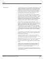
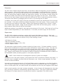
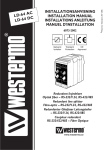
ControlMatrix PCU 2100
Redundant Load Sharing Power Supply
System Integrator’s Manual
PCU 2100 Integrator’s Manual
Intended to alert the user to the presence of uninsulated “dangerous voltage” within the product’s
enclosure that may be of sufficient magnitude to constitute a risk of electric shock to persons.
Intended to alert the user of the presence of important operating and maintenance (servicing)
instructions in the literature accompanying the product.
CAUTION: Risk of electrical shock — DO NOT OPEN!
CAUTION: To reduce the risk of electric shock, do not remove cover. No user serviceable parts inside. Refer
servicing to qualified service personnel.
WARNING: To prevent electrical shock or fire hazard, do not expose this appliance to rain or moisture. Before using this
appliance, read the operating guide for further warnings.
Este símbolo tiene el propósito, de alertar al usuario de la presencia de “(voltaje) peligroso” sin aislamiento dentro de la caja del producto y que puede tener una magnitud suficiente como para constituir riesgo de descarga
eléctrica.
Este símbolo tiene el propósito de alertar al usario de la presencia de instruccones importantes sobre la operación
y mantenimiento en la información que viene con el producto.
PRECAUCION: Riesgo de descarga eléctrica ¡NO ABRIR!
PRECAUCION: Para disminuír el riesgo de descarga eléctrica, no abra la cubierta. No hay piezas útiles dentro. Deje todo
mantenimiento en manos del personal técnico cualificado.
ADVERTENCIA: Para evitar descargas eléctricas o peligro de incendio, no deje expuesto a la lluvia o humedad este aparato
Antes de usar este aparato, Iea más advertencias en la guía de operación.
Ce symbole est utilisé dans ce manuel pour indiquer à l’utilisateur la présence d’une tension dangereuse pouvant
être d’amplitude suffisante pour constituer un risque de choc électrique.
Ce symbole est utilisé dans ce manuel pour indiquer à l’utilisateur qu’il ou qu’elle trouvera d’importantes instructions concernant l’utilisation et l’entretien de l’appareil dans le paragraphe signalé.
ATTENTION: Risques de choc électrique — NE PAS OUVRIR!
ATTENTION: Afin de réduire le risque de choc électrique, ne pas enlever le couvercle. Il ne se trouve à l’intérieur aucune
pièce pouvant être reparée par l’utilisateur. Confiez I’entretien et la réparation de l’appareil à un réparateur Peavey agréé.
AVERTISSEMENT: Afin de prévenir les risques de décharge électrique ou de feu, n’exposez pas cet appareil à la pluie ou à
l’humidité. Avant d’utiliser cet appareil, lisez attentivement les avertissements supplémentaires de ce manuel.
Dieses Symbol soll den Anwender vor unisolierten gefährlichen Spannungen innerhalb des Gehäuses warnen, die
von Ausreichender Stärke sind, um einen elektrischen Schlag verursachen zu können.
Dieses Symbol soll den Benutzer auf wichtige Instruktionen in der Bedienungsanleitung aufmerksam machen, die
Handhabung und Wartung des Produkts betreffen.
VORSICHT: Risiko — Elektrischer Schlag! Nicht öffnen!
VORSICHT: Um das Risiko eines elektrischen Schlages zu vermeiden, nicht die Abdeckung enfernen. Es befinden sich keine
Teile darin, die vom Anwender repariert werden könnten. Reparaturen nur von qualifiziertem Fachpersonal durchführen
lassen.
ACHTUNG: Um einen elektrischen Schlag oder Feuergefahr zu vermeiden, sollte dieses Gerät nicht dem Regen oder
Feuchtigkeit ausgesetzt werden. Vor Inbetriebnahme unbedingt die Bedienungsanleitung lesen.
Page 2
http://mediamatrix.peavey.com copyright 2003 All Rights Reserved
Cautions & warnings
To prevent electrical shock or potential fire hazards, do not expose this product to moisture or rain.
Before using this product, read the user manuals for further warnings and cautions.
The following cautions should be carefully observed when installing, wiring or using this product:
DO NOT use any other power supply or cable other than the one provided with this unit.
DO NOT remove the top cover of the unit. There are no user-serviceable parts inside. Refer
service to qualified personnel.
DO NOT use solvents or other cleaners to clean the unit. Basic external care requires only a
damp cloth. Disconnect the power supply cord before cleaning.
Read all safety and installation instructions and retain all documentation for further reference.
This product should be installed so that its mounting position does not interfere with proper
ventilation.
This product should not be installed or placed near a source of heat.
Power supply cords and associated connectors should be unplugged from the power source
when the unit is not used for long periods of time or stored.
If this product is to be mounted in an equipment rack, install rear support if required by the
rack manufacturer.
Care should be taken to ensure that the installation is clear of possible sources of contamination. Make sure that the product’s ventilation openings are not exposed to possible sources
of liquid, gases, or other contaminant's.
This product should be inspected by a qualified service technician if the power supply cord or
connector has been damaged, if the unit has been dropped, or if a foreign substance has
gained access to the interior electronic and electrical components.
The information contained in this manual is subject to change without notice. Peavey Electronics is
not liable for improper installation or configuration. The information contained herein is intended only
as an aid to qualified personnel in the design, installation and maintenance of engineered audio systems. The installing contractor or end user is ultimately responsible for the successful implementation
of these systems.
All creative content in this manual, including the layout, art design, content, photography, drawings,
specifications and all other intellectual property is Copyright ® 2003 Peavey Electronics Corporation.
All Rights Reserved. Features & specifications subject to change without notice.
Manual by WR
MediaMatrix - A Division Of Peavey Electronics Corp.
Page 3
PCU 2100 Integrator’s Manual
Thank You!
Thank you for purchasing the MediaMatrix® PCU 2100 Load
Sharing Redundant Power Supply. This product is designed
to provide years of trouble-free operation and high quality
performance. We are confident that you will find this product and other MediaMatrix products to be of the highest
quality.
This manual includes information of the product’s features,
functionality and performance characteristics. If you require
additional information that this manual does not provide,
please let us know. We are always looking for better ways
to provide information about our products, and your input is
always appreciated. If you have a comment about this manual or would like to make a suggestion, please write to:
Peavey Electronics Corp., MediaMatrix Division, 711 A St.,
Meridian MS, 39301. Thank you again for using
MediaMatrix!
What’s In The Box?
The PCU 2100 is packaged in a single container. This container includes the following items:
1- MediaMatrix PCU 2100 Load Sharing Redundant Power
Supply
1- IEC removable power supply line cord
(120 VAC Domestic, 230 VAC Export)
20- Three screw Euro connectors
24- Two-screw Euro connectors
4- Rack screws (#10-32) with washers
1- User Manual/Literature Package
If any of these items are missing, please contact your
Authorized Peavey MediaMatrix contractor/dealer.
Page 4
http://mediamatrix.peavey.com copyright 2003 All Rights Reserved
Welcome
Description
The PCU-2100 Load Sharing Redundant Power Supply is a 2U
rack-mounted power supply system for Control Matrix field
paging components. The PCU-2100 is designed to provide
redundant or passive operation from its two independent
power supply modules, or “banks”. Each bank is capable of
simultaneously powering up to eight Control Matrix PCU
Series stations and ten remote control panels.
Each bank is an fully independent power supply, internally
protected against load faults. Additional protection is provided for each output circuit and an auto-reset feature makes
restoring power to protected output loads easy, without
assistance from technical personnel. Front panel LED indicators alert the user to load status, as well as the health of
incoming primary supply voltages and fault conditions.
The PCU 2100 can operate in either Redundant or Dual
modes. A rear panel switch allows the system integrator to
determine the operating mode, while a front panel LED provides visual status for the user. When operating in
Redundant Mode, the PCU-2100 provides fully supervised,
redundant power supply outputs for up to eight PCU Series
paging stations and up to ten remote control panels. In this
mode, any failure of a primary supply module will automatically engage the second supply module, without interupption.
In Dual Mode, the second bank can be fully loaded, thereby
doubling the capacity of the PCU 2100 for applications that
do not require redundancy.
Each bank includes a Form-C, fault output connector for
interfacing external alarms or signalling equipment. A front
panel Fault LED provides visual status to the user.
Additional connectivity is provided for terminating the data
lines from ControlMatrix devices. Each bank includes a
wiring bus that allows for easy interface to head end equipment.
The PCU-2100 is designed for the systems contractor and
features rear panel connections for all supply circuits.
Removable Euro connector provide easy termination and
service for all outputs and fault contacts.
A removable IEC line connector is provided for the AC line.
The PCU 2100 is available for domestic (120VAC) and export
(230/240VAC) use.
MediaMatrix - A Division Of Peavey Electronics Corp.
Page 5
PCU 2100 Integrator’s Manual
Front Panel Features
1
2 3
4
5
6
2
2
4
5
6
1. REDUNDANT MODE LED Single color LED (Yellow) indicates that the
PCU 2100 is operating in Redundant Mode. If the unit is operating in Dual
Mode, this LED will not be illuminated.
2. ACTIVE LED Single-color blue LED indicates the presence of primary
power for the supply bank. When the LED is illuminated, the supply bank
is ON.
3. DC STATUS LED Single-color (Green) LEDs display status for each
supply voltage. There is a bi-polar supply and a single-ended supply in
each bank, with an LED for each leg. Green illumination indicates normal
operating condition. Absence of illumination indicates a loss of voltage on
the corresponding leg.
4. FAULT LED Single color red LED indicates Fault status. This Fault LED
will illuminate when a primary power supply fault has occurred, or there is
a load short. This LED is activated by the internal fault relay. Under normal operation, the LED is not illuminated.
5. +/-V 15V (STATION) OUTPUT LED’S Dual-color (Red/Green) LED
indicates the status of each bi-polar output group. Under normal operation, the LED will illuminate green. Under a fault condition, the LED will be
red. NOTE: This fault condition is monitored in parallel with the master
fault circuit, see number 4, above.
6. +12V (CONTROL PANEL) OUTPUT LED Dual-color (Red/Green) LED
indicates the status of the single-ended output. Under normal operation,
the LED will illuminate green. Under a fault condition, the LED will be red.
NOTE: This fault condition is monitored in parallel with the master fault circuit, see number 4, above.
Page 6
http://mediamatrix.peavey.com copyright 2003 All Rights Reserved
Panel Features
Rear Panel Features
1
2
3
4
5
6
7
8
9
4
5
6
7
8
1. IEC POWER CONNECTOR Standard IEC power receptacle for connecting AC Mains supply. Use only the supplied cable.
2. BANK “B” PRIMARY FUSE AC fuse protects the bank B primary
power supply.
3. BANK “A” PRIMARY FUSE AC fuse protects the bank A primary
power supply.
4. RS-485 IN CONNECTIONS Removable Euro connectors for terminating data lines from COntrolMatrix field devices. NOTE: There are no active
electronics or supervision for these connections.
5. STATION CONNECTIONS Removable Euro connectors for terminating
PCU Series paging stations. Each supply circuit is bi-polar (+15VDC, GND,
-15VDC) and requires a 3-conductor cable suitable for the output load.
There are four supervised circuits with two output connections for a total of
8 PCU Series stations.
6. CONTROL PANEL CONNECTIONS Removable Euro connectors for terminating ControlMatrix remote control panels. Each supply circuit is single-ended (+12VDC, GND) and requires a 2-conductor cable suitable for
the output load. There is one supervised circuit distributed to 4 connections. Maximum load is 10 ControlMatrix remote panels.
7. RS-485 OUT CONNECTION Removable Euro connector for distributing
data lines from ControlMatrix field devices to MediaMatrix head-end.
Shield pin is at chassis potential.
8. FAULT CONTACT CONNECTOR Removable Euro connector for terminating an external fault alarm or control circuit. This connector is internally coupled to a relay and provides a Form “C” connection (SPDT). The
contacts are rated for 600mA, 125 VAC; 2A at 30VDC.
9. REDUNDANT MODE SWITCH Two-position switch for configuring
redundant or dual-mode operation. The PCU 2100 is in Redundant Mode
when the switch is in the DOWN position (default mode), and in Dual Mode
when the switch is in the UP position. A front panel LED indicates the
active mode.
MediaMatrix - A Division Of Peavey Electronics Corp.
Page 7
PCU 2100 Integrator’s Manual
Connections
The circuits of the PCU 2100 are terminated using removable Euro connector blocks for three types of
connections:
• Bi-polar (three-pin) DC power for PCU Series paging stations
• Single-ended (two-pin) DC power for remote control panels
• Fault Contacts (three-pin)
Each connection requires termination to a removable Euro block (included) that plugs into a mating
connector header on the rear panel. The preferred method for making these connections consists of
three steps as shown in the illustration. As with any electronic connection, care should be taken to
ensure that the termination is solid. There should be no stray wire strands, kinks or nicks in the wire
jacket for a proper termination. Use a wire type that is appropriate for the load, cable length and
other jobsite conditions.
STEP 1. Carefully strip the cable jacket and the conductor insulation so that your wire
looks something like this. The distance between the end of the jacket and the tips of
the conductors should be approximately .075”. The strip length of the conductor wire
should be approximately .310” for proper termination into the Euro connector.
STEP 2. Carefully insert each conductor into the opening of the Euro connector. Take
care to ensure that polarity is observed and that the conductors are properly twisted to
make a solid connection. While holding the cable so each conductor is firmly seated in
the connector, carefully tighten down each screw of the connector. While turning each
screw, look closely at the wire and make sure that the action of the screw does not
“push” the wire out of the connector. Verify the integrity of your connection by gently
pulling on each conductor to ensure that it is terminated properly.
STEP 3. Take the completed wire/connector assembly and carefully plug it into the
matching connector header on the PCU 2100’s rear panel. Take care that you are plugging the connector into the proper set of pins on the header. There is no barrier
between adjacent circuits, so it is possible to connect to pins of an adjacent channel. If
you’re not careful, instead of connecting to Positive, Ground & Negative, you may end
up connecting Ground, Negative & Positive, etc. Your finished connection should look
like this.....
Configuration
Each bank of the PCU 2100 includes two separate supply outputs. For the PCU Series paging stations
there are 4 bi-polar circuits. Each of these circuits is capable of supplying power to 2 stations simultaneously, for a total of 8 loads for each bank. When operating in Dual Mode, a total of 16 paging
stations can be connected simultaneously. There is also one single-ended supply per bank for powering ControlMatrix remote control panels. This circuit can power up to 10 panels simultaneously from
the four connections provided for each bank. The outputs of the PCU 2100 outputs are regulated and
use special circuits designed to minimize losses and heat dissipation, giving high reliability. Maximum
combined current for all single-ended connectors is 0.5A per bank.
Additional connectivity is provided for terminating the RS-485 lines of ControlMatrix field devices.
Each bank includes an 8x1 “bus” that makes it easy to land multiple data lines. A single line can
then be extended to the MediaMatrix head-end, simplifying termination. NOTE: The RS-485 connectors are “pass through” circuits with no active electronics or supervision.
Page 8
http://mediamatrix.peavey.com copyright 2003 All Rights Reserved
Operation
Operational Modes
Once the loads are properly terminated, the only operational
consideration is whether to configure the PCU 2100 for Dual
Mode or Redundant Mode operation. A rear panel switch provides the selection, and a front panel LED indicates operating
mode.
DUAL MODE
Dual Mode operation configures both banks of the PCU 2100
to operate as independent power supply systems. In this
mode, all output circuits are fully active on each bank and
available for simultaneous use. In Dual Mode, a total of 16 PCU Series paging stations and 20
ControlMatrix control panels can be powered simultaneously. In Dual Mode there is no redundancy,
but the fault supervision and protection features are active.
REDUNDANT MODE
Although all circuits are supervised and protected, using the PCU 2100 in Redundant Mode provides
an additional level of stability. When operating the PCU 2100 in Redundant Mode the total capacity is
reduced to half of what Dual Mode provides. This is because the Bank B circuits are used as standby
circuits for loads connected to Bank A. When the PCU 2100 is in Redundant Mode, there is 1:1
redundancy for each load. If an output fails, the stand-by bank (Bank B) will take over, providing
seamless operation. In addition, the operator is notified of the failure by the integral fault contacts.
When using the PCU 2100 in Redundant Mode, only the Bank A output circuits are used. All Bank B
outputs are disconnected from their connections and cannot be used. The Bank B circuits operate in
“standby”, providing full 1:1 redundancy for each corresponding Bank A circuit. The switching
between redundant circuits is seamless, providing hands-free operation. Fault supervision alerts the
operator of a failure, while operation continues.
DUAL MODE
REDUNDANT MODE
Paging Station Capacity
16 (8 per bank)
8
Control Panel Capacity
20 (10 per bank)
10
Fault Supervision
Yes
Yes
Output Protection
Yes
Yes
Alarm Output
2
1
Redundancy
No
Yes
MediaMatrix - A Division Of Peavey Electronics Corp.
Page 9
PCU 2100 Integrator’s Manual
Protection
The PCU 2100 includes integral supervisory and protection features designed to provide seamless,
stable operation. Each power supply output circuit is protected by a self-resetting fuse. In case of
an overload or short, the circuit will shut down until the condition is removed. For the bi-polar supplies, the positive and negative outputs are supervised in tandem. An overload on either supply will
activate a crowbar circuit that will terminate both legs of the supply for the circuit. If this should
occur, the line input voltage must be cycled with sufficient OFF time to reset the protection circuitry.
This can be done either by unplugging the line cord or by removing the line fuses.
In addition, the primary DC supply circuits are protected to prevent the transformers from a cumulative overload. Front panel monitoring indicates the status of the main supply. There is a green LED
for each leg of the supply for each bank. Status LEDs indicate the health of the +15VDC, -15VDC
and +12VDC supply circuits. Under normal operation, these LEDs will illuminate (green). Under a
fault condition these LEDs will NOT be illuminated.
Additional protection is provided for each bank at the primary AC line input. Each bank of the AC line
input is fused independently for each transformer. If one fails, the other supply will still function.
Supervision
The PCU 2100 includes a supervisory system with integral Fault Status monitoring. Each bank
includes a front-panel Fault LED and corresponding rear-panel Fault Relay contacts. This supervisory
system will provide an alarm for failure of any of the following circuits:
•
•
•
•
AC Mains Line Power
Main DC Secondary Circuits
15V DC Output Circuits (+15V, -15V)
12V DC Output Circuits
The supervisory system provides constant monitoring of each circuit. If a fault condition on any of
these circuits is detected, the supervisory system activates an internal Form-C relay. The relay contacts are provided at the rear panel and include normally-open (N.O.) and normally-closed (N.C.)
contacts. The contacts are rated for low current applications and are used for signaling purposes
only. Usually, these contacts are connected to external equipment to translate an alarm condition to
the MediaMatrix audio processing system or third party equipment.
NOTE: These contacts are not designed to switch AC power line voltages.
In addition to the rear panel contacts, a front panel Fault LED is provided to indicate relay status. If
the Fault relay is engaged, the Fault LED will illuminate in red. Under normal operation, the Fault
LED will not be illuminated.
It should be noted that the behavior of the Fault Status system is dependent on the Fault Condition.
If an overload is detected on any circuit, the Fault LEDs will be red and the relay will be engaged. If
there is a total power loss, the LEDs will NOT be illuminated, but the relay will engage to fault status.
Under normal operation, the relay is always energized. A loss of power will disengage the relay naturally, providing a method for externalizing a general failure alarm. This type of supervision enables
the designer to configure alarms for any abnormal condition, regardless of the failure mode.
Page 10
http://mediamatrix.peavey.com copyright 2003 All Rights Reserved
Specifications
Specifications
Input Requirements
1A @ 120VAC
0.5A @ 230VAC
+V, -V, +12V (DC): 3x green, single-color.
Fault: 1x red, single-color.
Outputs 1-4: 4x green/red, dual-color.
Output +12V: 1x green/red, dual-color.
Bank Outputs (max each bank)
Power Supply
Bi-polar, four groups, two connectors per group,
+15VDC, 0.65mA per group; -15VDC, 0.3A per
group, referenced to ground.
Bi-polar max power: 1.85A (+V), 0.75A (-V)
quasi-regulated, 8 loads distributed across 4 circuits.
Single-ended, all outputs combined, +12VDC,
0.5A, referenced to ground.
Single-ended max power: 12VDC, 0.5A fully regulated, 10 loads max across single output.
Connections
Mechanical
3-position removable Euro block for each bi-polar
circuit, RS-485 output and fault contact.
Dimensions: 19"W X 3.5"H X 16.5"D
2-position removable Euro block for each singleended circuit and RS-485 inputs.
IEC power connector.
Front Panel Status
Weight: 16.8 Lbs unit weight
22.4 Lbs shipping weight
Construction: 18 gauge powder-coated CRS.
Supplied Accessories: IEC power cable, 3-position
Euro connectors, 2-position Euro connectors.
Status (AC Mains): 1x blue, single-color.
Architect’s & Engineer’s Specifications
Power Supply
The power supply shall be constructed in a steel, powder-coated chassis, suitable for installation in EIA equipment racks. The unit shall not exceed 2 EIA rack spaces, and shall include rear panel terminations exclusively.
The power supply shall be designed for either stand-alone or redundant operation, and shall be based on a dualsupply architecture. Each supply bank shall supply bi-polar DC power for up to 8 paging stations in redundant
mode, or up to 16 stations in stand-alone mode. An additional single-ended DC supply for each bank shall provide power for up to 10 remote control panels in redundant mode, or 20 panels in stand-alone mode. Each output circuit, for each bank, shall include an auto-resetting device that will protect the load and the power supply
output in the case of a load fault. When the fault is corrected, the output circuit shall either automatically reset
or require line voltage cycling, depending on the type of fault. When operating in redundant mode, the supply
shall operate with each bank in parallel, providing 1:1 redundancy for fail-safe operation. If a primary power
supply output circuit fails, the secondary supply bank shall provide power to the load without interupption. Each
bank shall include a fault contact supervision relay with external contacts. The relay contacts shall be rated for
500mA minimum, and shall provide N.O. and N.C. contacts (Form C). A corresponding front panel LED shall be
included for each bank to indicate fault status. The power supply shall include front panel LED status indicators
that provide visual status of all power supply circuits. These include, but are not limited to primary power
(mains). Additional LEDs shall be provided for the main supply and load circuit status for each group of supply
outputs. This includes bi-polar power with LEDs for each group and single-ended power for both banks. The
power supply shall be the MediaMatrix PCU 2100.
MediaMatrix - A Division Of Peavey Electronics Corp.
Page 11
TM
MediaMatrix®
A Division of Peavey Electronics Corp.
711 A St., Meridian Mississippi, 39301
601-483-9548
http://mediamatrix.peavey.com
Features & Specifications subject to change without notice
Copyright © 2003, All Rights Reserved
Printed in the USA 08/2003