1
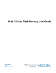
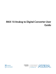
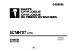
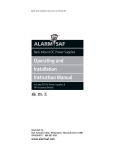
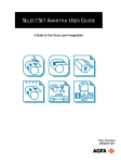
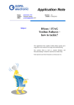
MAX 10 JTAG Boundary-Scan Testing
User Guide
Subscribe
Send Feedback
UG-M10JTAG
2015.05.04
101 Innovation Drive
San Jose, CA 95134
www.altera.com
TOC-2
Contents
Overview.............................................................................................................. 1-1
JTAG BST Architecture.......................................................................................2-1
JTAG Pins..................................................................................................................................................... 2-1
JTAG Circuitry Functional Model............................................................................................................ 2-1
JTAG Boundary-Scan Register...................................................................................................................2-2
Boundary-Scan Cells in MAX 10 I/O Pin.....................................................................................2-3
JTAG BST Operation Control............................................................................ 3-1
JTAG IDCODE ........................................................................................................................................... 3-1
JTAG Secure Mode...................................................................................................................................... 3-2
JTAG Private instruction............................................................................................................................ 3-2
JTAG Instructions........................................................................................................................................3-2
I/O Voltage Support in the JTAG Chain............................................................ 4-1
Enabling and Disabling JTAG BST Circuitry.....................................................5-1
Guidelines for JTAG BST....................................................................................6-1
Boundary-Scan Description Language Support................................................. 7-1
Additional Information for MAX 10 JTAG Boundary-Scan Testing User
Guide .............................................................................................................. A-1
Document Revision History for MAX 10 JTAG Boundary-Scan Testing User Guide..................... A-1
Altera Corporation
Overview
1
2015.05.04
UG-M10JTAG
Subscribe
Send Feedback
MAX® 10 devices support the IEEE Std.1149.1 (JTAG) boundary-scan testing (BST).
When you perform BST, you can test pin connections without using physical test probes and capture
functional data during normal operation. The boundary-scan cells (BSCs) in a device can force signals
onto pins, or capture data from pin or core logic signals. Forced test data is serially shifted into the BSCs.
Captured data is serially shifted out and externally compared to expected results.
Note: You can perform BST on MAX 10 devices before, after, and during configuration.
Related Information
• MAX 10 FPGA Configuration User Guide
Provides more information about JTAG in-system programming.
• JTAG BST Architecture on page 2-1
• JTAG Boundary-Scan Register on page 2-2
• JTAG BST Operation Control on page 3-1
• I/O Voltage Support in the JTAG Chain on page 4-1
• Enabling and Disabling JTAG BST Circuitry on page 5-1
• Guidelines for JTAG BST on page 6-1
• Boundary-Scan Description Language Support on page 7-1
© 2015 Altera Corporation. All rights reserved. ALTERA, ARRIA, CYCLONE, ENPIRION, MAX, MEGACORE, NIOS, QUARTUS and STRATIX words and logos are
trademarks of Altera Corporation and registered in the U.S. Patent and Trademark Office and in other countries. All other words and logos identified as
trademarks or service marks are the property of their respective holders as described at www.altera.com/common/legal.html. Altera warrants performance
of its semiconductor products to current specifications in accordance with Altera's standard warranty, but reserves the right to make changes to any
products and services at any time without notice. Altera assumes no responsibility or liability arising out of the application or use of any information,
product, or service described herein except as expressly agreed to in writing by Altera. Altera customers are advised to obtain the latest version of device
specifications before relying on any published information and before placing orders for products or services.
www.altera.com
101 Innovation Drive, San Jose, CA 95134
ISO
9001:2008
Registered
2
JTAG BST Architecture
2015.05.04
UG-M10JTAG
Send Feedback
Subscribe
MAX 10 JTAG interface uses four pins, TDI, TDO, TMS, and TCK.
JTAG Pins
Table 2-1: JTAG Pin Descriptions
Pin
TDI
Function
Serial input pin for:
• instructions
• test data
• programming data
TDO
Serial output pin for:
• instructions
• test data
• programming data
TMS
TCK
Input pin that provides the control
signal to determine the transitions of
the TAP controller state machine.
Description
• TDI is sampled on the rising edge of TCK
• TDI pins have internal weak pull-up resistors.
• TDO is sampled on the falling edge of TCK
• The pin is tri-stated if data is not being
shifted out of the device.
• TMS is sampled on the rising edge of TCK
• TMS pins have internal weak pull-up resistors.
The clock input to the BST circuitry.
—
All the JTAG pins are powered by the VCCIO 1B. In JTAG mode, the I/O pins support the LVTTL/
LVCMOS 3.3-1.5V standards.
JTAG Circuitry Functional Model
The JTAG BST circuitry requires the following registers:
• Instruction register—determines which action to perform and which data register to access.
• Bypass register (1-bit long data register)—provides a minimum-length serial path between the TDI and
TDO pins.
• Boundary-scan register—shift register composed of all the BSCs of the device.
© 2015 Altera Corporation. All rights reserved. ALTERA, ARRIA, CYCLONE, ENPIRION, MAX, MEGACORE, NIOS, QUARTUS and STRATIX words and logos are
trademarks of Altera Corporation and registered in the U.S. Patent and Trademark Office and in other countries. All other words and logos identified as
trademarks or service marks are the property of their respective holders as described at www.altera.com/common/legal.html. Altera warrants performance
of its semiconductor products to current specifications in accordance with Altera's standard warranty, but reserves the right to make changes to any
products and services at any time without notice. Altera assumes no responsibility or liability arising out of the application or use of any information,
product, or service described herein except as expressly agreed to in writing by Altera. Altera customers are advised to obtain the latest version of device
specifications before relying on any published information and before placing orders for products or services.
www.altera.com
101 Innovation Drive, San Jose, CA 95134
ISO
9001:2008
Registered
2-2
UG-M10JTAG
2015.05.04
JTAG Boundary-Scan Register
Figure 2-1: JTAG Circuitry Functional Model
•
•
•
•
Test access port (TAP) controller—controls the JTAG BST.
TMS and TCK pins—operate the TAP controller.
TDI and TDO pins—provide the serial path for the data registers.
The TDI pin also provides data to the instruction register to generate the control logic for the data
registers.
Instruction Register
TDI
TDO
UPDATEIR
CLOCKIR
SHIFTIR
TMS
TCK
Instruction Decode
TAP
Controller
UPDATEDR
CLOCKDR
SHIFTDR
Data Registers
Bypass Register
Boundary-Scan Register
a
Device ID Register
ISP Registers
JTAG Boundary-Scan Register
You can use the boundary-scan register to test external pin connections or to capture internal data. The
boundary-scan register is a large serial shift register that uses the TDI pin as an input and the TDO pin as an
output. The boundary-scan register consists of 3-bit peripheral elements that are associated with MAX 10
I/O pins.
Altera Corporation
JTAG BST Architecture
Send Feedback
UG-M10JTAG
2015.05.04
Boundary-Scan Cells in MAX 10 I/O Pin
2-3
Boundary-Scan Cells in MAX 10 I/O Pin
The MAX 10 3-bit BSC contains the following registers:
• Capture registers—connect to internal device data through OUTJ, OEJ, and PIN_IN signals.
• Update registers—connect to external data through PIN_OUT and PIN_OE signals.
Figure 2-2: User I/O BSC with JTAG BST Circuitry for MAX 10 Devices
The TAP controller generates the global control signals internally for the JTAG BST registers, shift,
clock, and update. The instruction register generates the MODE signal.
The data signal path for the boundary-scan register runs from the serial data in (SDI) signal to the serial
data out (SDO) signal. The scan register begins at the TDI pin and ends at the TDO pin of the device.
Capture
Registers
SDO
Update
Registers
INJ
PIN_IN
0
1
D
0
1
D
Q
D
INPUT
0
1
Q
INPUT
OEJ
From or
to Device
I/O Cell
Circuitry or
Logic Array
Q
D
OE
Q
OE
VCC
0
1
0
1
PIN_OE
0
1
PIN_OUT
OUTJ
0
1
D
Q
D
Q
OUTPUT
OUTPUT
SHIFT
CLOCK
UPDATE
Pin
Output
Buffer
SDI
JTAG BST Architecture
Send Feedback
HIGHZ
MODE
Global
Signals
Altera Corporation
2-4
UG-M10JTAG
2015.05.04
Boundary-Scan Cells in MAX 10 I/O Pin
Table 2-2: BSC Capture and Update Register for MAX 10 Devices
Captures
Pin Type
User I/O
Drives
Output
Capture
Register
OE Capture
Register
Input
Capture
Register
Output
Update
Register
OE Update
Register
Input Update
Register
OUTJ
OEJ
PIN_IN
PIN_OUT
PIN_OE
INJ
Note: All VCC and GND pin types do not have BSCs.
Altera Corporation
JTAG BST Architecture
Send Feedback
3
JTAG BST Operation Control
2015.05.04
UG-M10JTAG
Send Feedback
Subscribe
JTAG IDCODE
The IDCODE is unique for each MAX 10 device. Use this code to identify the devices in a JTAG chain.
Table 3-1: IDCODE Information for MAX 10 Devices
Device
Supply Option
Singlesupply
Dualsupply
Device
Version (4
Bits)
Part Number (16 Bits)
10M02
0000
0011 0001 1000 0001
000 0110 1110
1
10M04
0000
0011 0001 1000 1010
000 0110 1110
1
10M08
0000
0011 0001 1000 0010
000 0110 1110
1
10M16
0000
0011 0001 1000 0011
000 0110 1110
1
10M25
0000
0011 0001 1000 0100
000 0110 1110
1
10M40
0000
0011 0001 1000 1101
000 0110 1110
1
10M50
0000
0011 0001 1000 0101
000 0110 1110
1
10M02
0000
0011 0001 0000 0001
000 0110 1110
1
10M04
0000
0011 0001 0000 1010
000 0110 1110
1
10M08
0000
0011 0001 0000 0010
000 0110 1110
1
10M16
0000
0011 0001 0000 0011
000 0110 1110
1
10M25
0000
0011 0001 0000 0100
000 0110 1110
1
10M40
0000
0011 0001 0000 1101
000 0110 1110
1
10M50
0000
0011 0001 0000 0101
000 0110 1110
1
Manufacturer Identity LSB (1 Bit)
(11 Bits)
© 2015 Altera Corporation. All rights reserved. ALTERA, ARRIA, CYCLONE, ENPIRION, MAX, MEGACORE, NIOS, QUARTUS and STRATIX words and logos are
trademarks of Altera Corporation and registered in the U.S. Patent and Trademark Office and in other countries. All other words and logos identified as
trademarks or service marks are the property of their respective holders as described at www.altera.com/common/legal.html. Altera warrants performance
of its semiconductor products to current specifications in accordance with Altera's standard warranty, but reserves the right to make changes to any
products and services at any time without notice. Altera assumes no responsibility or liability arising out of the application or use of any information,
product, or service described herein except as expressly agreed to in writing by Altera. Altera customers are advised to obtain the latest version of device
specifications before relying on any published information and before placing orders for products or services.
www.altera.com
101 Innovation Drive, San Jose, CA 95134
ISO
9001:2008
Registered
3-2
UG-M10JTAG
2015.05.04
JTAG Secure Mode
JTAG Secure Mode
In JTAG secure mode, the device only allow SAMPLE/PRELOAD, BYPASS, EXTEST, and IDCODE JTAG
instructions.
Related Information
MAX 10 FPGA Configuration User Guide
Provides more information about the JTAG Secure Mode.
JTAG Private instruction
Caution: Never invoke the following instruction codes. These instructions can damage the device and
render it unusable:
•
•
•
•
10 0100 0000
10 0011 0000
10 1110 0000
10 0011 0001
JTAG Instructions
Instruction Name
SAMPLE/PRELOAD
EXTEST (1)
BYPASS
USERCODE
IDCODE
(1)
Instruction
Binary
Description
00 0000 0101 • Permits an initial data pattern to be an output at the device pins.
• Allows you to capture and examine a snapshot of signals at the
device pins if the device is operating in normal mode.
00 0000 1111 • Forces test pattern at the output pins and capture the test results at
the input pins.
• Allows you to test the external circuitry and board-level intercon‐
nects.
11 1111 1111 • Places the 1-bit bypass register between the TDI and TDO pins.
• Allows the BST data to pass synchronously through target devices
to adjacent devices during normal device operation.
00 0000 0111 • Places the 1-bit bypass register between the TDI and TDO pins.
• Allows you to shift the USERCODE register out of the TDO pin serially.
00 0000 0110 • Selects the IDCODE register and places it between the TDI and TDO
pins.
• Allows you to shift the IDCODE register out of the TDO pin serially.
HIGHZ, CLAMP, and EXTEST instructions do not disable weak pull-up resistors or bus hold features.
Altera Corporation
JTAG BST Operation Control
Send Feedback
UG-M10JTAG
2015.05.04
Instruction Name
JTAG Instructions
Instruction
Binary
3-3
Description
HIGHZ (1)
00 0000 1011 • Places the 1-bit bypass register between the TDI and TDO pins. The
1-bit bypass register tri-states all the I/O pins.
• Allow the BST data to pass synchronously through target devices to
adjacent devices if device is operating in normal mode.
CLAMP (1)
00 0000 1010 • Places the 1-bit bypass register between the TDI and TDO pins. The
1-bit bypass register holds I/O pins to a state defined by the data in
the boundary-scan register.
• Allow the BST data to pass synchronously through target devices to
adjacent devices if device is operating in normal mode.
USER0
USER1
JTAG BST Operation Control
Send Feedback
00 0000 1100 • Allows you to define the scan chain between the TDI and TDO pins
in the MAX 10 logic array.
• Use this instruction for custom logic and JTAG interfaces.
00 0000 1110 • Allows you to define the scan chain between the TDI and TDO pins
in the MAX 10 logic array.
• Use this instruction for custom logic and JTAG interfaces.
Altera Corporation
I/O Voltage Support in the JTAG Chain
4
2015.05.04
UG-M10JTAG
Send Feedback
Subscribe
A JTAG chain can contain several Altera and non-Altera devices.
The TDO pin of a device drives out at the voltage level according to the VCCIO of the device. The devices
can interface with each other although the devices may have different VCCIO levels.
For example, a device with 3.3-V VCCIO can drive to a device with 5.0-V VCCIO because 3.3 V meets the
minimum VIH on transistor-to-transistor logic (TTL)-level input for the 5.0-V VCCIO device.
MAX 10 devices can support 1.5-, 1.8-, 2.5-, or 3.3-V input levels, depending on the VCCIO voltage of I/O
Bank 1B.
To interface the TDI and TDO lines of the JTAG pins of devices that have different VCCIO levels, insert a
level shifter between the devices. If possible, construct the JTAG chain where device with a higher VCCIO
level drives to a device with an equal or lower VCCIO level. In this setup, you only require a level shifter for
shifting the TDO level to a level JTAG tester accept.
Figure 4-1: JTAG Chain of Mixed Voltages and Level Shifters
Must be 5.0-V
Tolerant
Must be 3.3-V
Tolerant
TDI
5.0-V
VCCIO
3.3-V
VCCIO
2.5-V
VCCIO
TDO
Level
Shifter
1.5-V
VCCIO
1.8-V
1.8-V
VVCCIO
CCIO
Tester
Shift TDO to Level
Accepted by Tester
if Necessary
Must be 1.8-V
Tolerant
Must be 2.5-V
Tolerant
© 2015 Altera Corporation. All rights reserved. ALTERA, ARRIA, CYCLONE, ENPIRION, MAX, MEGACORE, NIOS, QUARTUS and STRATIX words and logos are
trademarks of Altera Corporation and registered in the U.S. Patent and Trademark Office and in other countries. All other words and logos identified as
trademarks or service marks are the property of their respective holders as described at www.altera.com/common/legal.html. Altera warrants performance
of its semiconductor products to current specifications in accordance with Altera's standard warranty, but reserves the right to make changes to any
products and services at any time without notice. Altera assumes no responsibility or liability arising out of the application or use of any information,
product, or service described herein except as expressly agreed to in writing by Altera. Altera customers are advised to obtain the latest version of device
specifications before relying on any published information and before placing orders for products or services.
www.altera.com
101 Innovation Drive, San Jose, CA 95134
ISO
9001:2008
Registered
Enabling and Disabling JTAG BST Circuitry
5
2015.05.04
UG-M10JTAG
Subscribe
Send Feedback
The JTAG BST circuitry in MAX 10 devices is automatically enabled after the power-up.
To ensure that you do not inadvertently enable the JTAG BST circuitry when it is not required, disable the
circuitry permanently with pin connections as listed in the following table.
Table 5-1: Pin Connections to Permanently Disable the JTAG BST Circuitry in MAX 10 Devices
JTAG Pins
Connection to Disable
TMS
VCCIO supply of Bank 1B
TCK
GND
TDI
VCCIO supply of Bank 1B
TDO
Leave open
You must enable this circuitry only if you use the BST or ISP features.
© 2015 Altera Corporation. All rights reserved. ALTERA, ARRIA, CYCLONE, ENPIRION, MAX, MEGACORE, NIOS, QUARTUS and STRATIX words and logos are
trademarks of Altera Corporation and registered in the U.S. Patent and Trademark Office and in other countries. All other words and logos identified as
trademarks or service marks are the property of their respective holders as described at www.altera.com/common/legal.html. Altera warrants performance
of its semiconductor products to current specifications in accordance with Altera's standard warranty, but reserves the right to make changes to any
products and services at any time without notice. Altera assumes no responsibility or liability arising out of the application or use of any information,
product, or service described herein except as expressly agreed to in writing by Altera. Altera customers are advised to obtain the latest version of device
specifications before relying on any published information and before placing orders for products or services.
www.altera.com
101 Innovation Drive, San Jose, CA 95134
ISO
9001:2008
Registered
Guidelines for JTAG BST
6
2015.05.04
UG-M10JTAG
Subscribe
Send Feedback
Consider the following guidelines when you perform BST with the device:
• If the “10...” pattern does not shift out of the instruction register through the TDO pin during the first
clock cycle of the SHIFT_IR state, the TAP controller did not reach the proper state. To solve this
problem, try one of the following procedures:
• Verify that the TAP controller has reached the SHIFT_IR state correctly. To advance the TAP
controller to the SHIFT_IR state, return TAP controller to the RESET state and send the 01100 code
to the TMS pin.
• Check the connections to the VCC, GND, JTAG, and dedicated configuration pins on the device.
• Perform a SAMPLE/PRELOAD test cycle before the first EXTEST test cycle to ensure that known data is
present at the device pins when you enter EXTEST mode. If the OEJ update register contains 0, the data
in the OUTJ update register is driven out. The state must be known and correct to avoid contention
with other devices in the system.
• To perform testing before configuration, hold the nCONGFIG pin low.
© 2015 Altera Corporation. All rights reserved. ALTERA, ARRIA, CYCLONE, ENPIRION, MAX, MEGACORE, NIOS, QUARTUS and STRATIX words and logos are
trademarks of Altera Corporation and registered in the U.S. Patent and Trademark Office and in other countries. All other words and logos identified as
trademarks or service marks are the property of their respective holders as described at www.altera.com/common/legal.html. Altera warrants performance
of its semiconductor products to current specifications in accordance with Altera's standard warranty, but reserves the right to make changes to any
products and services at any time without notice. Altera assumes no responsibility or liability arising out of the application or use of any information,
product, or service described herein except as expressly agreed to in writing by Altera. Altera customers are advised to obtain the latest version of device
specifications before relying on any published information and before placing orders for products or services.
www.altera.com
101 Innovation Drive, San Jose, CA 95134
ISO
9001:2008
Registered
Boundary-Scan Description Language Support
7
2015.05.04
UG-M10JTAG
Subscribe
Send Feedback
The BSDL—a subset of VHDL—provides a syntax that allows you to describe the features of an IEEE Std.
1149.1 BST-capable device that can be tested. Test software development systems then use the BSDL files
for test generation, analysis, failure diagnostics, and in-system programming.
Related Information
IEEE 1149.1 BSDL Files
Provides more information about BSC group definitions.
© 2015 Altera Corporation. All rights reserved. ALTERA, ARRIA, CYCLONE, ENPIRION, MAX, MEGACORE, NIOS, QUARTUS and STRATIX words and logos are
trademarks of Altera Corporation and registered in the U.S. Patent and Trademark Office and in other countries. All other words and logos identified as
trademarks or service marks are the property of their respective holders as described at www.altera.com/common/legal.html. Altera warrants performance
of its semiconductor products to current specifications in accordance with Altera's standard warranty, but reserves the right to make changes to any
products and services at any time without notice. Altera assumes no responsibility or liability arising out of the application or use of any information,
product, or service described herein except as expressly agreed to in writing by Altera. Altera customers are advised to obtain the latest version of device
specifications before relying on any published information and before placing orders for products or services.
www.altera.com
101 Innovation Drive, San Jose, CA 95134
ISO
9001:2008
Registered
A
Additional Information for MAX 10 JTAG
Boundary-Scan Testing User Guide
2015.05.04
UG-M10JTAG
Subscribe
Send Feedback
Document Revision History for MAX 10 JTAG Boundary-Scan Testing
User Guide
Date
Version
Changes
May 2015
2015.05.04
Added note on about performing the boundary-scan testing in
'Overview'.
September 2014
2014.09.22
Initial release.
© 2015 Altera Corporation. All rights reserved. ALTERA, ARRIA, CYCLONE, ENPIRION, MAX, MEGACORE, NIOS, QUARTUS and STRATIX words and logos are
trademarks of Altera Corporation and registered in the U.S. Patent and Trademark Office and in other countries. All other words and logos identified as
trademarks or service marks are the property of their respective holders as described at www.altera.com/common/legal.html. Altera warrants performance
of its semiconductor products to current specifications in accordance with Altera's standard warranty, but reserves the right to make changes to any
products and services at any time without notice. Altera assumes no responsibility or liability arising out of the application or use of any information,
product, or service described herein except as expressly agreed to in writing by Altera. Altera customers are advised to obtain the latest version of device
specifications before relying on any published information and before placing orders for products or services.
www.altera.com
101 Innovation Drive, San Jose, CA 95134
ISO
9001:2008
Registered