1
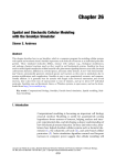
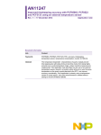
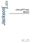
Platinum Studio ADC
Users Manual
Rev 2 (3/2012)
Digital Ouputs:
2 or 4 AES/EBU Balanced
MSB PRO I2S Output
(High Res Multichannel format convertible to USB)
Clock Jitter:Standard Clock 5 ppm TCXOs
Upgrade to Galaxy Femtosecond Clock with 77 femtosecond jitter
Clock In
Clock Out
Digital Trim Control:
+24dB - 181 dB in 0.1 dB steps
Output Sampling Frequency:
44.1Khz, 48Khz, 88.2Khz, 96Khz, 176.4Khz, 192Khz, 352.8Khz, 384Khz
Output Resolution:
up to
32 bits on PRO I2S, 24 bit on AES/EBU
Fully differential zero feedback discrete input buffers:
Low Gain Setting 0db: 26Vpp 9.28Vrms
High Gain Setting 0db: 13Vpp 4.64Vrms
Settable Gain: up to +60db (with plug-in)
MODELS: Stereo
8 Channel
1
ADC Users Manual
Unique Product - a Long History
The Platinum ADC has grown out of over 20 years of DAC development. Analog-to-Digital-Converters, ADCs, like DACs are generally
designed with a chip from someone like Analog Devices or Burr Brown and simply put in a box. As a result, all which use the same
chip sound about the same. Years ago we at MSB broke away from this mode by designing our own entirely discrete DAC. In years
past we have produced several ADCs, but by the conventional method. Finally, we have now addressed the analog-to-digital conversion
problem with the same care we have invested in the digital-to-analog conversion problem.
During the development of our Diamond DAC technology we were faced with the challenge of making a DAC more accurate than any
audio DAC ever produced. The first quandary we faced was finding an accurate and automated way to measure the output. Our first task
was to acquire the most accurate ADC we could. Well, as you can guess, nothing we could find came close to the precision we needed.
So once again, necessity drove us to develop the best ADC we could imagine. As the design was not restricted by a product requirement,
we simply did the best we could.
Setup and Quick Start
Presets - A group of presets make the ADC very simple to use. Very powerful features allow complete control, including
channel mixing, but the presets allow the user to select the type of recording being done and the MSB recommended
settings will all be loaded.
Power - The Platinum comes with a range of outboard power supplies. The supply automatically detects and switches
between 240V and 120V. This is not a switching supply that works at any voltage, but a linear supply with automatic
switching of the transformer leads. Always allow three to five hours for the Platinum to warm up and reach thermal
equilibrium.
Inputs - Connect the balanced analog inputs to your analog source. You have a high and low level gain setting. Any
gain setting can be locked in with a plug-in module. Generally gain should be set at the source.
Outputs
Connect the balanced or single-ended digital outputs to any recorder.
Burn-In
The concept of burn-in is little understood. Does it take your ears some time to get used to the incredibly detailed and life-like sound of
an MSB product or is something actually changing? The feedback we receive leads us to recommend at least 100 hours of burn-in on
this ADC. Customers generally recommend one month.
Expansion Options
The PRO I2S output on this ADC is very powerful. We envision several upgrade options that could
be plugged into this output including:
Extended Interface - We can plug in an extended interface that can be used remotely to setup and control
the ADC. It would have large level meters, sliders and buttons for setup. It could be customized to
interface to an existing studio system.
Computer Outputs - This interface contains up to 8 channels and the clock at full resolution. The
first computer interface under development is a USB2 output. Other outputs could be developed as
needed.
2
Presets for Quick setup
In each of these preset modes, the input pairs are mapped directly to the output
pairs. So in the 8 channel ADC, each pair of analog inputs creates a stereo digital output on each of the 4 digital outputs. In the Stereo ADC, the same input
pair is duplicated on each of the 2 digital outputs as a stereo pair. The clock
output defaults to word clock out.
Preset 16/44.1 – This is the best settings for recording music for use on an iPod
or burning to a CD. It can be modified to use 48 kHz if it will only be used for
computer or iPod sources but 44.1 kHz needs to be used for burning CDs.
Sample Rate:
Bit Depth:
Dither:
Channel Mix:
Delay:
Ground:
Gain:
DC Offset:
Filter:
44.1kHz
16
16
Normal
None
Connected
Low
Slow
Extended (Filter 2)
Preset 24/176.4 – Use this setting to record any high-resolution music over 48
kHz using the AES outputs. AES is limited to 192 kHz and 24 bits. The default
is 176.4 kHz as it is a convenient multiple of 44.1 kHz.
Sample Rate:
Bit Depth:
Dither:
Channel Mix:
Delay:
Ground:
Gain:
DC Offset:
Filter:
176.4kHz
24
24
Normal
None
Connected
Low
Slow
Standard (Filter 1)
Filter Options
This ADC has two filters in your tool box. You can select either one.
Filter 1 (standard) - This filter has a more gentle rolloff than filter 2. As a result it is perfect for higher
sample rates but should not be used at 44.1 or 48 kHz.
Filter 2 (extended) - This filter is a brickwall filter that extends all the way to nyquest. It is optimum
for low sample rate recordings.
3
Rear Panel Analog Details - 8 CH MODEL
8 Balanced Inputs – Each input is entirely independent, although input adjustments are grouped into pairs. So things like input gain can
only be set separately for each pair of inputs. Output gain and mixing levels can be set for each channel. The input impedance is 100
kOhms.
Analog Single-Ended Inputs – With a conversion cable, single-ended inputs can be used. The input impedance is 50 kOhms.
Input Levels – The ADC offers a high and low range input.
Low Gain Setting 0db: 26Vpp 9.28Vrms
High Gain Setting 0db: 13Vpp 4.64Vrms
Settable Gain: up to +60db (with plug-in)
Rear Panel Digital Details - (right)
Output Mixing - Each of the 10 output channels can be made up of any mix of the 8 input channels, at any levels. This allows multiple
mixes to be output simultaneously.
Balanced digital – The 4 AES/EBU Professional outputs provides 2 digital outputs from each XLR connector. The balanced nature of
this input allows great cable lengths as well as total noise immunity. Limited to 384 kHz, 24 bit data.
Single-ended digital – The Clock Output BNC connector can be set up as an additional digital output, giving you a 9th and 10th singleended digital channels. They are set up entirely independent of the other channels and are limited to 384 kHz, 24 bit data.
MSB Network – The MSB Network uses CAT-6 cabling. It provides an output for use with other MSB products. It can handle 8 channels
of data up to 384 kHz and 32 bits. It has an exact copy of what is output from the XLR outputs channels 1 to 8 except that it can handle
32 bit data.
RS-232 – The RS-232 interface is used for controlling the ADC using a remote system.
Clock Interface (advanced users)
Clock In – This clock input is for syncing to a studio system. It can be used with any of the standard clock rates. The input can be
configured to be either word clock, S/PDIF clock or a 512 times clock. The settings must match the clock provided. The 512 input
will determine if the output is a multiple of 44.1 or 48. The menu settings will determine which multiple is picked - 48, 96, etc.
512 times Clock - This clock is like a master clock. It is 512 times the frequency of the base or lowest sample rate. The following output
frequencies are made from each of two possible clocks as follows:
· 44.1, 88.2, 176.4 or 352.8 kHz sampling frequency source outputs or inputs a clock frequency of 22.5792 MHz
· 48, 96, 192 or 384 kHz sampling frequency source outputs or inputs a clock frequency of 24.576 MHz.
4
Rear Panel Analog Details - 2 CH MODEL
2 Balanced Inputs – All input and conversion settings are applied to both inputs. Only the output gain of each input channel and mixing
levels can be set for each of the 4 output channels. The input impedance is 25 kOhms.
Analog Single-Ended Inputs – With a conversion cable, single-ended inputs can be used. The input impedance is 12.5 kOhms.
Input Levels – The ADC offers a high and low range input.
Low Gain Setting 0db: 26Vpp 9.28Vrms
High Gain Setting 0db: 13Vpp 4.64Vrms
Settable Gain: up to +60db (with plug-in)
Rear Panel Digital Details - (right)
Output Mixing - Each of the 2 output channels can be made up of any mix of the 2 input channels, at any levels. This allows multiple
mixes to be output simultaneously.
Balanced digital – The AES/EBU Professional output provides 2 digital outputs from each XLR connector. The balanced nature of this
input allows great cable lengths as well as total noise immunity. Limited to 384 kHz, 24 bit data.
Single-ended digital – The Clock Output BNC connector can be set up as an additional digital output, giving you a 5th and 6th singleended digital channels. They are set up entirely independent of the other channels and are limited to 384 kHz, 24 bit data.
MSB Network – The MSB Network uses CAT-6 cabling. It provides an output for use with other MSB products. It can handle 8 channels of
data up to 384 kHz and 32 bits. In this case is provides just a stereo output identical to the XLR output except it can handle 32 bits.
Single-Ended Analog Input Cable
Word Clock - The word clock is the left/right clock which is the sample rate. So a 44.1khz word sync clock gives you a 44.1kHz L/R
clock which gives you a 44.1kHz S/PDIF output.
S/PDIF Clock - An S/PDIF signal is generated as an output at the sample rate. A clock can also be extracted from an S/PDIF input.
Internal Clock - The internal clock is on a header so it can be upgraded with a more accurate 512 times clock.
(Within the MSB Network connection is a 512 times low jitter clock interface that allows multiple Platinum products to be synchronized,
allows the Platinum Clock to be input or output. The interface is a propritary LVDS format that can only be negotiated over the network
by other MSB products.)
5
Power
Power Input – This product must be plugged into a Signature
or Diamond MSB power base with both analog and digital
supplies.
Power Base Connection Diagram
Features and Controls
This A/D is fully configurable with word lengths and bit depth adjustable up to with 32-bit output resolution, and sample rates up to
384 kHz. There are several grounding options that can be selected including complete isolation. Each input has a +24 db/- 181 db trim
adjustment and a full digital mixing of all 8 channels is possible, all with simple setup controls.
Front Panel Controls
Although the user interface is very simple and easy to use, in depth menus allow complete control of the DAC.
Menu Button – The square button is single purpose. It will enter the setup mode at the top of the menu tree. If in the setup,
and it doesn’t matter where, this button will exit the setup, save the settings and return to the normal operational mode.
Right/Left Arrows – Used for navigation in the menu structure.
Star Button - The star button changes the sample rate.
Input/Volume Knob - The large knob will navigate up and down in the menu structure.
Display - The display shows the sample rate and bit depth. There is also a bar graph. The output meter is shown on the display. It’s a
dual bar graph. One shows the average level and the other shows the peak level. Each line represents 2dB. It will display from 0dB
to -32dB in 2 dB steps. It shows all the input channels at the same time.
6
Global Menu Options
The high level menu options have to do with global settings. They are settings that impact directly all the conversion parameters and all
the output channels. Parameters that impact individual output channels are in the next section. See the Menu tree for details.
Presets - Two basic presets are provided. Details are in the quick start section at the beginning of the manual. A preset is not really a
menu setting, but a shortcut which just sets all the other menus to a predetermined setting. From there you can change parameters.
Selecting the preset again just resets all the parameters again.
Sample Rate - Any output sampling rate can be directly selected. This selection is applied to the sampling of all the analog inputs and
is the sample rate of all the digital outputs. The best sample rate to use is generally defined by the output media for the final use of
the material. If a CD is going to be prepared, then sample at 44.1 kHz. This will sound MUCH better than sampling at 192 kHz and
then downsampling with your sound processing software to 44.1 kHz. We do a MUCH better job in creating a perfect 44.1 master
than your sound processing software.
Clock Source - There are five options for clock source. In most cases, the best results can be achieved with our amazing 5 ppm accurate
internal 512 times clocks. Resist the temptation to use the studio clock unless you must. Even better consider using our clock output
as the studio master clock. See the details of the clock calculations in the clock interface box above.
Individual Channel or Global Menu Options
The second level menu options can either be set up globally or can be set for each input pair, or output channel. See the Menu tree for
details.
Input Ground - This setting literally connects the ground pins of the analog input XLR to the ADC ground or it keeps it completely
disconnected (equivalent to clipping the pin). The ADC will work perfectly with the ground disconnected if the balanced signals are
within the common mode specs. It’s used to get rid of ground loops. There are other uses as well. You must be aware that without
the ground connected you are relying on the 28 volt common mode range of the input (+/- 14 volts). If the inputs exceed it by a small
amount, there is no risk in damaging the ADC, if they exceed it by a lot, you risk damaging the ADC.
Input DC Offset Mode - This feature determines how the ADC handles DC offset on the inputs. The DC offset is removed by a very slow
high-pass filter. It assumes the signal on average should be zero and is a negative feedback loop and slowly steps to keep the average
at 0. It takes about 30 seconds to remove the DC offset of the ADC on power up, so they are all very very slow.
Setting
1
2
Outcome
Slow - removes less than one LSB and does not effect output resolution
Medium - removes more than one LSB per sample
Input Filter Select - Two filters are provided with a different rolloff rate. Each is optimized for a different range on sample rates.
Setting
1
2
Outcome
Best for sample rates of 44.1 and 48 kHz and below
Best for sample rates over 48 kHz
Output Dither Offset - Adjustable from 0 to 32. MSB uses a triangular probability density function to add dither. By default, the dither
setting matches the bit depth setting. In special cases, such as when signal post processing is expected you may want to add more dither,
knowing you will be truncating the output later. For example if you are recording for a 16 bit CD but have a post processing step in
mind, you would set the bit depth to 24 bits and the dither to +8. You will get better post processing results with the extra resolution
but the dither is correct for your final 16 bit output.
Output Bit Depth - Normally this should be set just as sampling frequency would, for the output media. So for CDs, set to 16 bits, etc.
Individual Output Channel and Mixing Menu Options - 8 Channel ADC
The third level menu options are setup for each output channel. See the Menu tree for details. Each digital output channel can be set up
to be any combination of any of the input channels at any level. This very powerful mixing funtion is done at high resolution and can
never be accomplished at this quality level again. So for each digital output channel, you scroll through all 8 analog inputs and set:
Output Level - This analog input is adjusted from +24 to -181 dB in 0.1 dB steps.
Downmix - Downmix or do not downmix this input.
Individual Output Channel and Mixing Menu Options - Stereo Channel ADC
The third level menu options are setup for each output channel. See the Menu tree for details. Each digital output channel can be set
up to be any combination of any of the input channels at any level. This very powerful mixing funtion is done at high resolution and
7
Gain
H/L
Input 4
Ground
Lift
Gain
H/L
Input 5
Ground
Lift
Gain
H/L
Input 6
Ground
Lift
Gain
H/L
Input 7
Ground
Lift
Gain
H/L
Input 8
Ground
Lift
Gain
H/L
Pair 3
Output 1
Pair 4
Mixed at level X
Not Mixed
AES/EBU 1
One of the most powerful features of MSB products is the PRO I2S
network. Most new MSB products have a PRO I2S connection available.
The MSB PRO I2S has the following capability:
•
•
AES/EBU 3
AES/EBU 4
BNC Out*
*Note: This output is only active
when clock out is set to “S/PDIF”
The MSB PRO I2S Network
•
•
AES/EBU 2
Output 10
Ground
Lift
Output 9
Input 3
Pair 2
Output 8
Gain
H/L
Output 7
Ground
Lift
Output 6
Input 2
Pair 1
Output 5
Gain
H/L
Output 4
Ground
Lift
Output 3
This chart shows how all inputs
can be level adjusted and
mixed into any number of output
channels. The default is a one-toone mapping.
You can actually output different
mixes at the same time using the
mixing feature.
Input 1
Output 2
Multichannel ADC Mixing
Chart
Works with standard CAT6 cable
Simultaneous transmission of 8 audio channels with 32 bit
resolution at 384 kHz sampling rate.
MSB CAN Interbox communication Bus (for communications
between boxes)
Low Jitter master clock distribution from the DAC back to the
Transport.
can never be accomplished at this quality level again. So for
each digital output channel, you scroll through both analog inputs
and set:
Output Level - This analog input is adjusted from +24 to -181 dB.
Downmix - Downmix or do not downmix this input.
This network is our answer to 384 kHz audio transmission and
multichannel transmission in the same package. We provide network
outputs on our own transports and offer a source upgrade to your
transport as well. With multichannel sources, up to 8 channels of
decoded data can be sent through one wire to separate DACs. CAT6
wire is very convenient as it has become the standard for all computer
networks. Several cables are available for connecting MSB transports
to the Platinum Line including CAT6 cable at any length up to 80 feet.
(Do not use CAT7 cable.)
8
Level Meter
The output meter is shown on the display. It’s a dual bar graph.
One shows the average level and the other shows the peak level.
Each line represents 2dB. It will display from 0dB to I think
-32dB. It shows all the input channels at the same time.
MSB Network Connector
Load preset 16/44.1
Load preset 24/176.4
Load user preset 1
Load user preset 2
Save user preset 1
Save user preset 2
Presets
Stereo ADC Menu Tree
44.1 kHz
48.0 kHz
88.2 kHz
96.0 kHz
176.4 kHz
192.0 kHz
352.8 kHz
384.0 kHz
Sample rate
Clock source
Internal oscillators
MSB upgrade
Word sync input (BNC)
512x clock (BNC)
S/PDIF (BNC)
Clock output
Word Sync
512x Clock
S/PDIF
Off
Digital out 1
Dither
Variable
0-32
Digital out 2
Bit depth
Variable
8-32
Input gain
High gain
Low gain
Channel 1
Left on/off
Off
On
Left ground
Ground con
Ground discon
Channel 2
Left level
Variable
+24dB - -180dB
Right ground
Ground con
Ground discon
Right on/off
Off
On
DC offset mode
Slow DC Offset
Med. DC Offset
Right level
Variable
+24dB - -180dB
Filter select
Filter 1
Filter 2
Display mode
Bar graph
Numerical
Display
Brightness
1-15
Display On/Off
Display On
Display Off
9
Presets
Sample rate
Load preset 16/44.1
Load preset 24/176.4
Load user preset 1
Load user preset 2
Save user preset 1
Save user preset 2
44.1 kHz
48.0 kHz
88.2 kHz
96.0 kHz
176.4 kHz
192.0 kHz
352.8 kHz
384.0 kHz
Clock source
Internal oscillators
MSB upgrade
Word sync input (BNC)
512x clock (BNC)
S/PDIF (BNC)
Clock output
Word Sync
512x Clock
S/PDIF
Off
Global
(overrides
settings)
Dither
Variable
0-32
Bit depth
Variable
8-32
Input gain
High gain
Low gain
Input
ground
Ground con
Ground discon
DC offset
mode
Slow DC Offset
Med. DC Offset
Filter select
Filter 1
Filter 2
Channe
Pair 1
(Ch 1 + 2)
Input gain
High gain
Low gain
Output
channels
Channe
Pair 2
(Ch 3 + 4)
Input
ground
Ground con
Ground discon
Chanel
Input channels
Display
Brightness
1-15
Display On/Off
Display On
Display Off
Pair 3
(Ch 5 + 6)
DC offset
mode
Slow DC Offset
Med. DC Offset
Pair 4
(Ch 7 + 8)
Filter select
Filter 1
Filter 2
8 CH ADC Menu Tree
10
*Note: O
channe
and 10
the BNC
ble
2
Dither
Variable
0-32
Upgrades and Modifications
Removal of the cover - Unplug the AC power. Work on a
clean surface. Start by removing the 14 screws of the cover.
Carefully remove and set aside the cover.
Galaxy Femtosecond Clock Upgrade - Remove the cover.
ble
2
Bit depth
ain
ain
Channel 1
ON/OFF
Variable
8-32
Unplug the old clock and plug the new clock in the clock
upgrade header. Install the clock mounting screw located in
the cover of the clock box. Re-Install the cover.
Other Upgrades - Check the instructions supplied with the
upgrade.
Quality Check
Off
On
Each Platinum is comprehensively tested and the actual
outputs measured.
Troubleshooting
Channel 1
level
con
discon
Variable
+24dB - -180dB
under development.
Warranty
Offset
Offset
1
2
Off
On
Channel 2
level
Variable
+24dB - -180dB
Channel n
ON/OFF
Off
On
Channel n
level
Variable
+24dB - -180dB
Channel 8
ON/OFF
Off
On
Channel 8
level
Variable
+24dB - -180dB
Channel 1
Channel n
n
et
et
All MSB products carry a one year warranty. No returns
accepted without an RMA. Upon receipt, MSB will repair
or replace any defective product. All product shipped FOB
Aptos. Shipping and shipping damage is the responsibility of
the consignee.
Channel 2
ON/OFF
Chanel 10*
*Note: Output
channels 9
and 10 are
the BNC out
11