1
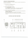
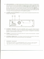
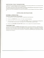
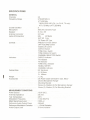
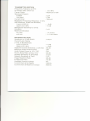
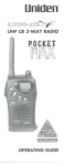
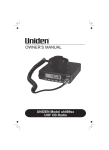
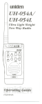
uni
~n@
UHF CB TRANSCEIVER
OWNER'S
MANUAL
FlLJI-I-O11
IBIIdm
o
n~
UH-O11
\...
T.CALL
11
"
Cl
110
11
0
I::J
I::J
I::J
I::J
.- .-
.--,
TX RX
CACUP I ,_, ,-, !
= = =
L-~ L~J
= =
cs
~o
M~
DESCRIPTION
YourUNIDEN Model SUNDOWNER UH-011 represents one of the most advanced Mobile
Station type radio ever designed for use in the Citizens Band Radio Service. It will operate
on any of the 40 frequencies designated as citizens band channels by the Department of
Communications. Your Model SUNDOWNER UH-011 features a frequency synthesizing
circuit with PHASE LOCK LOOP techniques to assure ultraprecise Frequency control.
This radio has been Type Accepted and Type Certified by the D.O.C.
WARNING
Before transmitting with your transceiver, you must obtain a Department of Communications (D.O.C.) Citizens Radio Licence. Obtain an application form from the
D.O.C. Before completing the form you should read the conditions governing the licensing and operation of the C.R.S. A brochure can be obtained from the D.O.C.
After completing the application form, mail it with the appropriate fee to the Superintendant Regulatory of Licensing in the State or territory in which the station will be
operated.
CHANNEL INFORMATION
This radio has been designed to provide high level performance in the Citizens Band Radio
Service, which is comprised of the following frequency assignments:
Channel Frequency
inMHz
476.425
476.450
476.475
476.500
476.525
476.550
476.575
476.600
476.625
476.650
476.675
476.700
476.725
476.750
Channel
1
2
3
4
5
6
7
8
9
10
11
12
13
14
Channel
15
16
17
18
19
20
21
22
23
24
25
26
27
28
Channel Frequency
inMHz
476.775
476.800
476.825
476.850
476.875
476.900
476.925
476.950
476.975
477.000
477.025
477.050
477.075
477.100
Channel
29
30
31
32
33
34
35
36
37
38
39
40
Channel Frequency
inMHz
477.125
477.150
477.175
477.200
477.225
477.250
477.275
477.300
477.325
477.350
477.375
477.400
DUPLEX OPERATING FREQUENCIES
CHANNEL
CH1
CH2
CH3
CH4
RX
TX
476.425 MHz 477.175 MHz (CH31)
476.450"
477.200 "(CH32)
477.225 "(CH33)
476.475"
476.500"
477.250 "(CH34)
CHANNEL
CH5
CH6
CH7
CH8
RX
476.525
476.550
476.575
476.600
TX
MHz
"
"
"
477.275
477.300
477.325
477.350
MHz (CH35)
"(CH36)
"(CH37)
"(CH38)
INSTALLATION
MOBILE STATION INSTALLATION
Plan the location of the transceiver and microphone bracket before starting the installation. Select a location that is convenient for operation and does not interfere with the driver
or passenger in the vehicle. The radio should be securely fastened to some solid face, using the mounting bracket and self-tapping screws which are provided.
MOBILE STATION ANTENNA
Since the maximum allowable power output of the transmitter is limited by the D.O.C., the
antenna is a very important factor affecting transmission distance. It is for this reason that
we strongly recommend that you install only a quality antenna in your new citizens band
system. You have just purchased a superior transceiver. Don't diminish its performance
by installing an inferior antenna.
Only a properly matched antenna system will allow maximum power transfer from the 50ohm transmission line to the radiating element. Your Uniden dealer is qualified to assist
you in the selection of the proper antenna to meet your application requirements.
For automobile installation, the whip antenna may be used with good effect. The most efficient and practical installation is a full quarter wave whip antenna mounted on the rear
deck or fender top midway between the rear window and bumper.
A short "loaded" whip antenna is more convenient to install on your automobile, although
the efficiency is less than a full quarter wave whip antenna.
For marine installation, consult your dealer for information regarding an adequate grounding system and prevention of electrolysis between fittings in the hull and water.
GROUND SYSTEM
Connect the red DC power cord from the transceiver to the positive, or (+), battery terminal
or other convenient point and con nect the black power lead to the chassis or veh icle frame,
or (-) battery terminal.
SELCALL
SELCALL (Selective Calling) is a special Squelch System which quiets your receiver until
it receives an Encoded signal from another set which matches the one installed in your set.
This means your set will remain quiet and not receive idle chit chat or other signals until the
station you want to hear calls.
SELCALL is not initially installed in your set (each one has to be individually programmed)
but may be purchased as an option.
OPERATING PROCEDURE TO RECEIVE
1. Be sure that the power source, antenna and microphone are connected to the proper
connectors before going to the next steps.
2. Turn the unit ON by rotating the OFF/VOLUME Control clockwise.
3. Set the CHANNELSELECTOR switch to the desired channel.
4. Set the OFF/VOLUME Control to a comfortable listening level.
5. Listen to the background noise from the speaker. Turn the SQUELCH control slowly
clockwise until the noise JUST disappears (no signal should be present). Leave the
control at this setting. The SQUELCH is now properly adjusted. The receiver will remain quiet until a signal is actually received. Do not advance the control too far, or
some of the weaker signals will not be heard.
OPERATING PROCEDURE TO TRANSMIT
CAUTION
-
The transceiver Voltage Standing Wave Ratio (V.S.W.A.) measurement must be
performed priorto the use of the transmitter. A V.S.W.R. ratio in excess of 2:1 may
damage the transmitter.
1. Be sure the operator has read and understands D.G.C. Rules and Regulations priorto
operating the transmitter.
2. Select the desired channel.
3. If the channel is clear, depress the PRESS- TO-TALK switch on the microphone and
speak in a normal voice.
PREVENTIVE MAINTENANCE
At six to twelve month intervals, the following system checks should be made:
1. Check Standing Wave Ratio (SWR).
2. Inspect all electrical connections to ensure that they are tight.
3. Inspect antenna coaxial cable for wear or breaks on shielding.
4. Inspect all screws and other mounting hardware for tightness.
OPERATOR TROUBLESHOOTING
Should the unit malfunction or not perform properly, the operator should perform the
procedures indicated below:
1. If the transceiver is completely inoperative.
* Check the power cord and fuse.
2. If trouble is experienced with receiving.
* Check OFF/VOLUME control setting.
* Be sure SQUELCH is adjusted properly. Is the radio over-squelched?
* Check to see that the radio is switched to an operational mode.
3. If trouble is experienced with transmitting.
* Check to see that the transmission line (coaxial cable) is securely connected to the
ANTENNA CONNECTOR.
*
*
Be sure that the antenna is fully extended for proper operation.
Be sure that all transmission line (coaxial cable) connections are secure and free of
corrosion.
CONTROLS AND THEIR FUNCTIONS
2
1
r-'-
T.CALL
= == = =
14
.13
' '-' ,il
I
'-.' LU
1.
PRESS- TO- TALK MICROPHONE: The receive and transmit are controlled by the
PRESS- TO-TALK switch on the microphone. Press the switch on the microphone to
activate the transmitter; release the switch to receive. When transmitting, hold the
microphone two inches from the mouth and speak clearly in a normal voice. The microphone provided with your radio is detachable Iow impedance dynamic type.
2.
TONE CALL SWITCH: This switch is reserved for optional SELCALL operation.
Push the T. CALL switch, (when this action is taken, TX indicator will flash), then,
TONE SIGNAL will be generated and it opens the Squelch of the other units which
have the same tone squelch function.
3.
TONE SQUELCH SWITCH: This switch is reserved for optional SELCALL operation.
Push the T.SQ switch while receiving the TONE SIGNAL. Then, the Circuit of the
SQUELCH is automatically opened.
4.
S-INDICA TOR: The signal indicator will illuminate to monitor the relative strength
of the signal.
5.
TX INDICATOR: This LED indicates red while transmitting.
6.
RX INDICATOR: Lights during the receive mode whenever a station is being received, or whenever the SQUELCH control is adjusted fully counter clockwise.
7.
TONE CALL INDICATOR: When a SELCALL module is installed: While receiving
TONE SIGNAL, this LED will be on.
8.
DUPLEX INDICATOR: When the channel indicated by the CHANNEL INDICATOR
and Duplex memory is programmed, this LED is turned on.
9.
CHANNEL INDICATOR: LED indicates the channel number in use.
10. FRONT MICROPHONESOCKET
11.
OFF/VOLUME CONTROL: Turn clockwise to apply power to the radio and to set the
audio volume to the desired listening level. Turn fully counterclockwise to turn the
radio OFF.
12.
SQUELCH CONTROL: This SQUELCH Control is rotated to cut off or eliminates
received background noise in the absence of an incoming signal. For maximum receive sensitivity, it is desired that the control be rotated only to this point where the receive background noise or ambient background noise is eliminated. Turn the control
fully counterclockwise, then slowly rotate clockwise until ~he receive noise disappears. Any signal to be heard must now be slightly stronger than the average received noise. Further clockwise rotation will increase the threshold level which a
signal must overcome in order to be heard. Only strong signals will be heard at the
maximum clockwise setting.
13.
DUPLEX SWITCH: To program semi-duplex operation for channel 1 through channel8. Select the channel you would like to use as repeater channel (check your local
repeater station frequency first) and push the DUP switch and then DUP indicator will
turn on. Select next repeater channel and push the DUP switch again and so on. To
put the channel back to normal simplex operation, just select the DUPLEX programmed channel by channel selector and push the switch so that the DUP indicator
turns off to indicate that channel is no longer repeater frequency off-set channel. CH
1 through CH 8 are programmed for the repeater operation.
14.
CHANNEL SELECTOR SWITCH: This switch selects the desired channel for transmission and reception.
.15
.16
.17
J
5» EX
SP.
@r
I
@I
(
@
ANT
(
15.
EXTERNAL SPEAKER: The External Speaker Jack is used for remote receiver
monitoring. The external speaker should have 8-ohm impedance and be rated to
handle at least 4.0 watts. When the external speaker is plugged in, the internal
speaker is automatically disconnected.
16.
POWER: This jack permits connection of the D.C. power to the transceiver. A power
cord is supplied with the radio.
17.
ANTENNA CONNECTOR: This female connector permits connection of the transmission line cable male connector (M-Type) to the transceiver.
MEMORY BACKUP
Channels maintained in the SUNDOWNER UH-O11 memory are protected
from less by a built-in capacitor which protects the memory for up to
12 hours when you disconnect
the DC Power Cable.
SERVICING YOUR TRANSCEIVER
It is the user's responsibility to see that this radio is operating at all times in accordance with
the D.O.C. Citizens Radio Service regulations.
We highly recommend that you consult a qualified radiotelephone technician for the servicing and alignment of this UHF CB radio product.
Please refer to the WARNING information contained in the 2nd page of this Owner's Manual.
OPERATING INSTRUCTIONS
NORMAL OPERATION
RECEIVE OPERATING PROCEDURE
1. Connect the 13.8 Volt power lead, microphone and antenna.
2. Rotate the SQUELCH control (12) fully counterclockwise.
3. Switch the radio on by turning the OFF/VOLUME control (11) clockwise and adjust for
a comfortable volume level, and adjust for a comfortable squelch level.
4. Rotate the CHANNEL SELECTOR switch (14) to select the required channel.
TRANSMITTING
To transmit, depress the PRESS- TO- TALK switch (1) on the microphone. Hold the microphone 5-10 cm from your mouth and slightly to one side so that your voice does not project
directly into the microphone (this provides best results). Speak at a normal level. Never
raise your voice or shout into the microphone. Whenever the PTT switch is pressed, the TX
indicator (5) will light.
SPECIFICA TIONS
GENERAL
Channels
Frequency Range
Crystal Oscillator
Microphone
Speaker
Antenna Connector
Jacks & Connectors
Controls
Indicators
Cabinet Size
I
Weight
Accessories
MEASUREMENT CONDITIONS
Power Source
Antenna Impedance
Test Temperature
Modulation Frequency
Mean Signal Input Level
Reference Audio Output' Power
Reference Modulation Deviation
Audio Output Load
: 40
: 476.425 MHz to
477.400 MHz
* REPEATER USE (CH-1 to CH-8, TX only):
477.175 MHz to 477.350 MHz
:2
:
:
:
:
600 ohm, Dynamic Type
8ohm, 3W
M-Type
Mic
4P Metal
EXT SP 3.5~
DC Power 3P Type
: PRESS-TO-TALK Switch
OFF/VOLUME Control
SQUELCH Control
DUPLEX Switch
TONE CALL Switch
TONE SQUELCH Switch
CHANNEL SELECTOR Switch
: DUPLEX Indicator
TX Indicator
RX Indicator
TONE CALL Indicator
SIGNAL METER
CHANNEL Indicator
: W: 154.5 mm
H: 52.5mm
D: 189mm
: 1.2 kg
: DC Power Cable with Built-in fuse, Microphone, Microphone Hanger
Mounting Bracket
Screw (2), Washer (2) For Microphone Hanger
Screw (2), Washer (2) For Mounting Bracket
:
:
:
:
:
:
:
:
13.8V (DC)
50 ohm
25°C
1 kHz (RX/TX)
1000 pV
500mW
:!:3 kHz Deviation
8 ohms resistive
-- ---
~---
TRANSMITTER SECTION
Frequency Tolerance at 25°C
,(5 minutes after switch on)
Carrier Power
: I 0.5 kHz
: Maximum of 5W
Spurious Emission
: 5/1W
In Band
: 1/1W
: 1500 mA
Out Band
Current Drain
Modulation Frequency Response: (1 kHz,
OdB reference, at 600 Hz deviation)
Lower at 500 Hz
:
:
Upper at 2.5 kHz
Microphone Sensitivity for 3 kHz
Deviation
:
Maximum Deviation
at 1 kHz
:
at 6 kHz
.
-6dB
+5dB
1mV
I4.75 kHz
I 1.5 kHz MAX
RECEIVER SECTION
Sensitivity for 12 dB SINAD
Overall Audio Fidelity
(1 kHz, 0 dB reference)
Lower at 500 Hz
: 0.25/1V
Upper at 2.5 kHz
Adjacent Channel Selectivity ( I25
Maximum Audio Output Power
Audio Output Power at 10% THD
Hum & Noise Ratio at Input 1mV
Squelch Sensitivity at Threshold
Squelch Sensitivity at Tight
Image Rejection Ratio
IF Rejection Ratio
Oscillator Dropout Voltage
Current Drain at No Signal
Current Drain at Maximum Output
kHz)
: +3dB
: -8dB
: 65 dB
: 3W
: 2W
: 40 dB
: 0.2/1V
: 1/1V
: 60dB
: 70 dB
: 9V
: 300mA
: 600mA
-,
MEMO
\
--.;;;;c-
- ---------
'-.
WARRANTY
Uniden UH-O11 Australian 1 Year Warranty.
Note: Please keep your sales docket as it provides evidence of warranty.
WARRANTOR:Uniden Australia Pty. Ltd.
ELEMENTSOF WARRANTY:Unidenwarrants to the original retail ownerfor the duration
of this warranty, its UH-011 UHFCB Product (hereinafter referredto as the Product),to be
free from defects in materials andcraftsmanship with onlythe limitationsor exclusionsset
out below.
WARRANTY DURATION: This warranty to the original user only shall terminate and be of
no further effect One (1) Year after the date of original retail sale. This warranty will be
deemed invalid if the product is (A) Damaged or not maintained as reasonable and necessary, (B) Modified, altered, or used as part of any conversion kits, subassemblies, or any
configurations not sold by Uniden, (C) Improperly installed, (D) Repaired by someone
other than an authorised Uniden Repair Agent for a defect or malfunction covered by this
warranty, (E) Used in conjunction with any equipment or parts or as part of a system not
manufactured by Uniden, (F) Installed, programmed or serviced by anyone other than an
authorised Uniden Repair Agent.
PARTS COVERED: This warranty covers the transceiver unit, microphone and power
lead only.
STATEMENT OF REMEDY: In the event that the product does not conform to this warranty
at any time while this warranty is in effect, the warrantor will at its discretion, repair the defect or replace the product and return it to you without charge for parts or service. THIS
WARRANTY DOES NOT COVER OR PROVIDE FOR THE REIMBURSEMENT OR PAYMENT OF INCIDENTAL OR CONSEQUENTIAL DAMAGES. Some states do not allow this
exclusion or limitation of incidental or consequential damages, sothe above limitation may
not apply to you.
WARRANTY CARD: If a warranty card had been included with this product then please fill
it in and return it to us within 14 days of purchase. Your name and the serial number of the
product will then be registered in our database and this will help us to process your claim
with greater speed and efficiency should you require a warranty service on the product.
PROCEDURE FOR OBTAINING PERFORMANCE OF WARRANTY: In the event that the
Product does not conform to this warranty, the Product should be shipped or delivered,
freight pre-paid, with evidence of original purchase, (eg/ a copy of the sales docket),'to the
warrantor at:
unlden
AUSTRALIA PTY LTD - SERVICE DIVISION
345 Princes Highway, Rockdale, Sydney. NSW 2216.
Ph (02) 599 3100 Fx (02) 599 3278
Customers in other States should ship or deliver the Product
freight pre-paid to their nearest Uniden Authorised Repair Centre.
(Contact Uniden for the nearest Warranty Agent to you).
Adelaide (08) 3652588
Brisbane (07) 290 1188
Melbourne (03) 335 4322 Perth (09) 362 9306
UTUAO1846AA
@ Copyright
1992 Uniden Australia
Pty, Ltd,
Printed in the Philippines