1
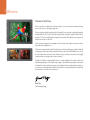
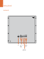
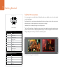
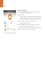
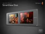
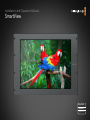
Installation and Operation Manual SmartView Mac OS X™ Windows™ December 2011 2 Welcome Welcome to SmartView. We hope you share our dream for the television industry to become a truly creative industry by allowing anyone to have access to the highest quality video. Video monitoring is needed everywhere in a facility. SmartView Duo provides two completely independent and beautiful 8 inch LCD screens in a 3RU rack housing less than an inch thick. SmartView HD provides an amazing 17" LCD screen in a 6RU rack housing less than an inch thick. All SmartView monitors support SD, HD and even 2K video via 3 Gb/s SDI! Video monitoring is designed to work straight out of the box and our free utility provides the user with an easy and intuitive configuration tool. This instruction manual should contain all the information you’ll need on installing your SmartView, although it’s always a good idea to ask a technical assistant for help if you are not sure what IP addresses are, or if you don’t know much about computer networks. SmartView is easy to install, however, there are a few slightly technical preferences you may need to set after you install it. We think it should take you approximately 5 minutes to complete installation. Please check our web site at www.blackmagic-design.com and click the support page to download the latest updates to this manual and SmartView software. Lastly, please register your SmartView when downloading software updates so we can keep you updated when new software is released. We are constantly working on new features and improvements, so we would love to hear from you! Grant Petty CEO Blackmagic Design Contents SmartView Operation Manual 4 Getting Started Planning your SmartView Installation 4 SmartView Duo product diagram 6 SmartView HD product diagram 7 Optimizing the Viewing Angle 8 Plugging in SDI Monitoring 10 SmartView Duo Connection Diagram 11 SmartView HD Connection Diagram 12 Connecting SmartView to a Network 13 Direct Ethernet Connection 14 Ethernet Network Switch 15 Installing the Blackmagic SmartView Utility Software 16 Updating the Firmware in Your SmartView 17 Configuring Blackmagic SmartView Utility Software 18 Network Settings Pane: Device Name 19 Network Settings Pane: Configure Address 19 Monitor Settings Pane: Brightness, Contrast, Saturation 20 Monitor Settings Pane: Adjust both monitors together 20 Monitor Settings Pane: Always display SD in 16:9 20 Monitor Settings Pane: Identify monitor 21 Add Device 21 Copy/Paste Display Settings 22 23 Tally Port Pin Connections 24 25 33 Help Developer Information Blackmagic 2K Format 26 Blackmagic SmartView Ethernet Protocol v1.1 29 Warranty Information 4 Getting Started Planning your SmartView Installation SmartView monitors are perfect for any facility which requires rack-based monitoring. SDI input connections support auto-detection of SD, HD or 3 Gb/s SDI including 2K video. SmartView Duo features two monitors with 8" LCD screens, 2 SDI inputs, 2 reclocked SDI loop-through outputs, 2 Ethernet ports, tally connector, USB 2.0 connector and configuration software for Mac OS X and Windows. The simultaneous display of different video formats is supported on the two, independent monitors. SmartView Duo is 3 RU (rack units) high and less than an inch deep. SmartView HD features a 17" LCD screen, 1 SDI input, 1 reclocked SDI loop-through output, 2 Ethernet ports, tally connector, USB 2.0 connector and configuration software for Mac OS X and Windows. SmartView HD is 6 RU high and less than an inch deep. The Blackmagic SmartView Utility can be used to change network settings and monitor settings. The computer display resolution needs to be 1280 x 800 or higher to display the Blackmagic SmartView Utility. While SmartView monitors display video without needing any configuration, any network settings needs to be configured prior to deployment. Network configuration is performed using a direct USB 2.0 connection to a computer. You will need to provide a standard USB 2.0 type A-B male cable to connect SmartView to your computer. A laptop computer with a USB 2.0 port would be ideal for this task. This same USB cable can be used for applying occasional firmware updates downloaded from the Blackmagic Design website. Programmable firmware can provide new features, compatibility with new hardware and support for new formats. The SmartView firmware update utility runs on a Mac OS X or Windows computer and uses the USB 2.0 connection to update SmartView. Local monitor configuration can be performed with a direct USB 2.0 connection between your computer and a SmartView unit. Remote monitor configuration can be performed via an Ethernet network switch. The network switch also enables multiple computers to configure SmartView monitor settings. Additional SmartView units can be daisy-chained together using the active loop-through Ethernet OUT port on each unit so as to only use a single port on your switch. Daisy-chaining SmartView via Ethernet also avoids having to run Ethernet cables back to the network switch for each SmartView unit. Power must be supplied to all units for Ethernet daisychaining to work. Remote monitor configuration can also be performed via a direct Ethernet connection between your computer and SmartView. No network switch is required in this configuration which is great if you need to install and set up SmartView fast. Additional SmartView units can be daisy-chained together using the active loop-through Ethernet OUT port on each unit. Power must be supplied to all units for Ethernet daisychaining to work. 5 Getting Started A tally connector is provided for use with switcher and automation systems. The 9-pin D connector wiring description is printed on the rear of the unit showing contact closures to display red, green or blue tally borders on each, independent monitor. If SmartView is to be installed high up in an equipment rack, you may wish to physically invert the LCDs for the optimum viewing angle. The images on the LCDs will automatically flip to the correct orientation when they sense an inversion. A number 02 size Pozidriv screwdriver is required to disconnect and reconnect the faceplate from its rear assembly. This is a simple procedure and does not involve opening the rear assembly. SmartView includes a universal power supply with international power socket adapters for all countries. To stop power from being accidentally disconnected, a cable tie point is included just below the power socket to lock down the power connection. You will need to provide a mains power socket for the universal power supply. 6 Getting Started SmartView Duo Monitor 1 Monitor 2 SD/HD-SDI In & Out Monitor 2 Tally Ethernet with loop through USB Monitor 1 SD/HD-SDI In & Out +12V main power supply connection 7 Getting Started SmartView HD Tally Ethernet with loop through USB SD/HD-SDI In & Out +12V main power supply connection 8 Getting Started Optimizing the Viewing Angle Before you install SmartView high up in a rack, it is a good idea to check the optimum viewing angle by connecting an SDI video signal and then temporarily inverting the unit. The unit will automatically sense the inversion and flip the video images to the correct orientation. The following procedure describes how to invert the unit while keeping any labelling in the correct orientation on the front face plate. A number 02 size Pozidriv screwdriver is required. Step 1. Remove the screws from the top, bottom, left and right sides of SmartView. SmartView Duo has 10 screws and SmartView HD has 18 screws. Step 2. Lift the front face plate away from the rear assembly as illustrated. You may wish to perform a test inversion, to check the optimum viewing angle, before bolting SmartView high up in a rack. 9 Getting Started Step 3. Invert the rear assembly. Step 4. Reinstate the face plate on the inverted rear assembly. Step 5. Reinstate the screws in the SmartView chassis. SmartView is now ready to be installed in a high position in a rack. Once bolted into a rack, SmartView will continue to display the optimum viewing angle, even if bumped, as there are no external knobs or adjustments to mishandle or to come loose. 10 Getting Started Plugging in SDI Monitoring SmartView monitors feature regular BNC connectors to make it easy to connect cables from other SDI equipment including switchers, cameras, capture cards, decks and disk recorders. After powering on the SmartView and connecting an SDI video source to an SDI In connector, the video should immediately be visible on the corresponding monitor and no configuration is required. Each monitor has its own, independent, 3 Gb/s SDI input as well as a loop-through output. SD, HD and 2K signals are automatically detected and supported by the SDI input and loop-through connections. When multiple SmartView units are daisy-chained together via SDI, all units must be powered on to support the loop-through SDI output. The independent monitors on each SmartView Duo enable one monitor to display a YUV 4:2:2 signal while the other receives RGB 4:4:4. One monitor could be showing NTSC while the other shows PAL. One monitor could be showing HD while the other shows 2K. There are many possible combinations but it is all as simple as connecting a single SDI cable to each monitor. Following are examples of different SDI signals connecting to SmartView. Connecting a 4:2:2 SDI or HD-SDI source to SmartView Duo The illustration on the following page shows the SDI output of an HyperDeck Shuttle disk recorder connected to an SDI IN port on SmartView Duo. The HyperDeck Shuttle can send standard definition or high definition YUV 4:2:2 video to SmartView Duo. Connecting a dual-link 4:4:4 HD or 2K-SDI source to SmartView Duo If you wish to view an RGB 4:4:4 dual-link HD-SDI or dual-link 2K-SDI signal on SmartView Duo, you will need to use a dual-link to single-link SDI converter such as an HDLink Pro from Blackmagic Design. The illustration on the following page shows the dual-link HD-SDI outputs of a Sony HDCAM SR deck converted to a 3 Gb/s SDI signal, by HDLink Pro, and then connected to an SDI IN port on SmartView Duo. Connecting an SDI or HD-SDI source to SmartView HD As with SmartView Duo, you can connect a YUV 4:2:2 or RGB 4:4:4 signal to the SDI input of SmartView HD and SmartView HD will accept standard definition, high definition or even 2K video via SDI. The example in the next couple of pages shows the high definition multi-view output of an ATEM switcher connected to the SDI IN port on SmartView HD. 11 Getting Started SmartView Duo Connection Diagram HyperDeck Shuttle disk recorder +12V POWER HDMI IN HDMI OUT SDI IN This illustration shows two examples of different SDI hardware connected to SmartView Duo simultaneously. The HyperDeck Shuttle disk recorder is providing a YUV 4:2:2 signal at the same time that the HDCAM SR deck is providing an RGB 4:4:4 signal. SDI OUT SmartView Duo ANALOG I/O DIGITAL I/O (AES/EBU) AUDIO OUTPUT CH1 CH2 CH3 MONITOR OUTPUT R L CUE REF INPUT CH4 1 TIME CODE IN DIGITAL I/O OUTPUT AUDIO CH1/2 CH3/4 CH1/2 CH3/4 CH5/6 CH7/8 CH5/6 CH7/8 CH9/10 CH11/12 CH9/10 CH11/12 HD SDI INPUT FC OUT B INPUT MONITOR A 1 B INPUT B(OPTION) MONITOR 2 OUT HD REF OUT 1 IN INPUT AUDIO 2 SYNC REMOTE 2 PARALLEL I/O (50P) OUT 2 HD SDI OUTPUT 1 A 2 A MONITOR A SD OUT COMPOSITE (MONITOR) REMOTE 1-IN (9P) REMOTE 1-IN/OUT (9P) RS422 VIDEO CONTROL B(OPTION) B(OPTION) B(OPTION) FORMAT CONV. OUT (OPTION) 1 MONITOR 2 SD SDI OUTPUT 1 USB HDCAM SR deck 2 MONITOR HDLink Pro 3D 12 Getting Started SmartView HD Connection Diagram This illustration shows the multi-view SDI output of an ATEM switcher connecting to the SDI input of the SmartView HD. IN 5 SDI IN 4 SDI IN 6 SDI PROG USB 2.0 MULTI-VIEW SDI AES/EBU IN PROG HDMI IN 4 HDMI IN 3 HDMI IN 2 HDMI IN 1 HDMI Note: All SDI and HDMI video connections are SD/HD switchable. IN 3 SDI MULTI-VIEW 1 SmartView HD 12V POWER SWITCHER CONTROL REF IN PROG SDI ATEM Television Studio PROG SDI 13 Getting Started Connecting SmartView to a Network It is not necessary to connect SmartView to a computer in order to view SDI video and you can skip this section if you simply want to view video without making any adjustments. However if you wish to remotely adjust the monitor settings, a network connection will be required. SmartView has two 10/100Base-T Ethernet ports. You can connect the IN port to a network switch or directly to an Ethernet port on your computer. The OUT port can be connected to additional SmartView units or to other network devices such as a Videohub router. Power must be supplied to all SmartView units for Ethernet daisy-chaining to work. If you want to connect several SmartView units without using IP addresses from your existing studio network, or if you don't have an existing network, simply connect them directly to the Ethernet port on your computer. This is also a fast way to connect SmartView units via Ethernet as you don't need to run any cables back to a network switch. If you want to connect several SmartView units to your studio's network, you only need to connect one SmartView to the network switch and the rest can be daisy-chained to each other so you don't have to run multiple cables back to a network switch. Power must be supplied to all units for daisy-chaining to work. Connecting SmartView to a network switch means that any Mac or Windows PC on the network can change SmartView settings. Any Mac or Windows laptop computer can also change SmartView settings via a WiFi connection if your network includes a wireless access point. You will need to carry out the following steps to connect SmartView to a local area IP based network. Step 1. Securely connect and switch on the power supply included with your SmartView. Step 2. Connect the SmartView to a network switch, or directly to a computer, with a standard RJ45 Ethernet cable. 14 Getting Started Direct Ethernet Connection You can connect the Ethernet port of a computer directly to a SmartView without needing a network switch. Additional SmartView units can be daisy-chained to each other so you don't have to run multiple cables back to a network switch. Power must be supplied to all units. 15 Getting Started Ethernet Network Switch If you want to connect several SmartView units to your studio's existing network, you only need to connect one SmartView to the network switch. The rest can be daisy-chained to each other so you don't have to run multiple cables back to a network switch. Power must be supplied to all units. Ethernet Network Switch Client Computers 16 Getting Started Installing the Blackmagic SmartView Utility Software It is not necessary to install any software in order to view SDI video and you can skip this section if you simply want to view video without making any adjustments. However if you wish to adjust the network or monitor settings, you will need to install the Blackmagic SmartView Utility software. The Blackmagic SmartView Utility software runs on the latest Snow Leopard and Lion versions of Mac OS X. On the Windows platform, SmartView Utility software runs on both 32 and 64-bit versions of Windows 7 with the latest service packs installed. Testing on previous versions of these operating systems is not conducted and so it is always best to keep up to date with the latest versions of Mac OS X and Windows. The Blackmagic SmartView Utility software only needs to be installed on one computer but can be installed on multiple, networked computers if desired. While the CD supplied with SmartView contains the software installer, we recommend you visit www.blackmagic-design.com to ensure you have the latest version. Mac OS X installation: Drag the Blackmagic SmartView Utility to the Applications folder On Mac OS X, open the supplied CD, or downloaded disk image, and drag the Blackmagic SmartView Utility to your Applications folder. On Windows, open the supplied CD, or downloaded disk image, and double-click on the SmartView installer. Follow the onscreen prompts to install the software. Windows installation: Follow install prompts. 17 Getting Started Updating the Firmware in Your SmartView Once the software installation has been completed and SmartView is powered on, it is a good idea to check that the firmware in the SmartView is up to date. Step 1. Launch the Blackmagic SmartView Utility. Step 2. Connect your SmartView unit to the computer via USB 2.0. Blackmagic SmartView Utility application icon Step 3. If no firmware update is required, you will simply see the settings used by your SmartView. Settings can be changed now if desired and this is a good opportunity to give each SmartView a unique "Device Name". Please skip the rest of the steps in this section as your SmartView is already up to date. If a firmware update is required, the following message will appear: "Firmware Update Required. The firmware on this device is out of date. Would you like to update it now?" Click Yes. The update will take 4 or 5 minutes to complete. Step 4. The message, "The firmware has been successfully updated," should appear at completion of the update. Click OK to dismiss the message. Settings can be changed now if desired and this is a good opportunity to give each SmartView a unique "Device Name". This message will appear if a firmware update is required. The update will take about 4 or 5 minutes to complete. Step 5. You can now unplug the USB cable from your SmartView. 18 Getting Started Configuring Blackmagic SmartView Utility Software After installing the Blackmagic SmartView Utility software, launch the Blackmagic SmartView Utility and it should immediately search your network for any SmartView units by using the Bonjour service discovery protocol. Any discovered units will be listed in the SmartView Monitors pane with an Ethernet network icon next to their name. Select the name of the desired SmartView and you will be able to change the device name and also the monitor settings for each monitor on each SmartView. Network settings will remain grayed out and can only be changed via USB. Blackmagic SmartView Utility application icon SmartView Duo and SmartView HD with Ethernet network icons next to their names. The Blackmagic SmartView Utility automatically searches your network for any SmartView units. Two units have been found in this picture. 19 Getting Started SmartView HD with a USB icon next to its name. If no SmartView monitors are found on the network, some units might not have received an IP address via DHCP and it will be necessary to manually configure each unit with appropriate network settings. To do so, connect a SmartView to your computer via a standard USB 2.0 type A-B male cable and launch the Blackmagic SmartView Utility. If the utility prompts you to update the firmware, refer to the previous section named "Updating the firmware in your SmartView". The USB-attached SmartView unit will be automatically selected in the SmartView Monitors pane and will show a USB icon next to its name. You will be able to change all device name, network settings and monitor settings for the USB-attached unit. Network Settings Pane: Device Name It is a good idea to change the default "device name" of SmartView so each unit is easy to identify on a network, e.g. "Field Cameras 1&2", "Multi-View Output", "2K feeds", etc. To change the device name, select the desired SmartView unit from the SmartView Monitors pane and then edit its device name from the Network Settings pane. You can use Blackmagic SmartView Utility to make changes to the device name when connected to the SmartView hardware via Ethernet or USB. The device name must not have a space character at the start or end of the name. If the software detects an invalid device name, the text will turn red as you are typing. The device name will turn red, if you type a space at the start or end of the name. Network Settings Pane: Configure Address By default, SmartView uses DHCP to automatically obtain an IP address from your network. You will probably want to leave the "Configure Address" option set to "Using DHCP" unless there is no DHCP server present. In the absence of a DHCP server, you may wish to enable the "Internet Sharing" feature of Mac OS X 10.6 and 10.7, or the "Internet Connection Sharing" feature of Windows 7, to provide DHCP addresses to any directly-attached SmartView units. This will avoid having to manually assign static IP addresses to each unit. You can use this feature to provide DHCP addresses even though your computer might not have an Internet connection. Internet sharing is described in the Mac OS X and Windows 7 Help documentation. If DHCP cannot be used in your configuration, choose to configure the address "Using Static IP". Please ask your system administrator for a spare IP address to avoid creating an IP conflict on your network. You will need to specify a unique IP address for each SmartView unit as well as a common subnet mask. It is unnecessary to change the default value in the "Gateway" field unless you intend to connect your SmartView units to a network gateway, such as an Internet router. You can use Blackmagic SmartView Utility to make changes to the network settings when connected to the SmartView hardware via USB. Network settings cannot be changed via Ethernet. Network settings can be set to use DHCP or a Static IP address and can only be changed via USB. 20 Getting Started Monitor Settings Pane: Brightness, Contrast, Saturation You can use Blackmagic SmartView Utility to make changes to the brightness, contrast and saturation of the monitors when connected to SmartView hardware via Ethernet or USB. Monitor Settings Pane: Adjust both monitors together When this setting is enabled, any changes made to the brightness, contrast and saturation will be applied to both SmartView Duo monitors. Yellow borders will surround both monitors in the software interface to indicate that changes to brightness, contrast and saturation will be applied to both monitors. Deselect this setting if you wish to make independent changes to the two monitors. Click on Monitor 1 or Monitor 2 and a yellow border will surround the selected monitor, in the software interface, to indicate that changes to brightness, contrast and saturation will only be applied to the selected monitor. You can use Blackmagic SmartView Utility to enable or disable the "Adjust both monitors together" setting when connected to SmartView Duo hardware via Ethernet or USB. SmartView Duo monitor settings can be adjusted independently or together Monitor Settings Pane: Always display SD in 16:9 When this setting is enabled, widescreen anamorphic standard definition video will be displayed in the 16:9 aspect ratio on a SmartView HD monitor. Leave this option disabled when viewing traditional 4:3 aspect ratio standard definition video otherwise the video will appear to be stretched. You can use Blackmagic SmartView Utility to enable or disable the "Always display SD in 16:9" setting when connected to SmartView HD hardware via Ethernet or USB. A yellow border will appear around the selected monitor(s) in the Blackmagic SmartView Utility. Enable "Always display SD in 16:9" when viewing anamorphic standard definition video on SmartView HD. 21 Getting Started Monitor Settings Pane: Identify monitor Enable this setting to display a white border on the selected SmartView monitor. If you have several SmartView units on a network, this setting makes it easy to identify the selected monitor. The white border will appear both on the LCD monitor and in the Blackmagic SmartView Utility software interface. If this setting is used with SmartView Duo in conjunction with the "Adjust both monitors together" setting, the white border will be displayed on both monitors. You can use Blackmagic SmartView Utility to enable or disable the "Identify monitor" setting when connected to SmartView hardware via Ethernet or USB. A white border will appear around the selected LCD monitor(s) when the "Identify monitor" feature is enabled. Add Device If you already know the IP address of a SmartView but it hasn't automatically appeared in the SmartView Monitors pane, you can add the SmartView manually. To do so, go to the Device menu and choose Add Device or alternatively click Add Device (+) at the bottom of the SmartView Monitors pane. Type in the IP address of the SmartView monitor and click OK. The software will verify the presence of the SmartView unit and add it to the SmartView Monitors list. If the Blackmagic SmartView Utility does not find a SmartView at the specified address, it will not add the unit to the list and will instead present a warning, "A SmartView Monitor could not be found." You can manually add a SmartView, by IP address, to the list of SmartView Monitors You can use Blackmagic SmartView Utility to manually add a SmartView when connected to SmartView hardware via Ethernet or USB. 22 Getting Started Copy/Paste Display Settings If you have already set up one SmartView unit with monitor settings that you would like to apply to other SmartView units, you can copy and paste the settings to those other units. To do so: • select the already configured unit from the SmartView Monitors pane • go to the Device menu, or alternatively click the action button (gear icon) at the bottom of the SmartView Monitors pane, and choose Copy Display Settings (Ctrl-C, Cmd-C) • select the unit, whose monitor settings you wish to change, from the SmartView Monitors pane. • go to the Device menu, or alternatively click the action button (gear icon) at the bottom of the SmartView Monitors pane, and choose Paste Display Settings (Ctrl-V, Cmd-V) You can use Blackmagic SmartView Utility to copy and paste the display settings when connected to the SmartView hardware via Ethernet or USB. Copy and Paste Display Settings 23 Getting Started 5 4 3 2 1 Tally Port Pin Connections It is not necessary to connect the tally port of SmartView and you can skip this section if you do not intend to use the tally feature. Each SmartView Duo screen features independent tally borders in red, green or blue which can be used to indicate the status of a video signal such as on-air, preview or recording. 9 8 7 6 SmartView tally port SmartView Duo Tally Pin Connections Pin The 9-pin D-sub tally port on SmartView accepts contact closure signals from switchers and automation systems. Please refer to the accompanying SmartView tally pin connections diagram for information about wiring the tally port for use with your switcher or automation system. Function 1 Monitor 1 Red 2 Monitor 1 Green 3 Monitor 1 Blue 4 Ground 5 Ground 6 Ground 7 Monitor 2 Red 8 Monitor 2 Green 9 Monitor 2 Blue SmartView HD Tally Pin Connections Pin SmartView HD can also display a red, green or blue tally border. Function 1 Red 2 Green 3 Blue 4 Ground SmartView Duo showing green and red tally borders 24 Help There Are Four Steps To Getting Help. Step 1. Check out the Blackmagic Design web site www.blackmagic-design.com and click on the “Support” page for the latest support information. Step 2. Call your dealer. Your dealer will have the latest technical updates from Blackmagic Design and should be able to give you immediate assistance. We also recommend you check out the support options your dealer offers as they can arrange various support plans based on your workflow requirements. Step 3. The next option is to email us with your questions using the web form at www.blackmagic-design.com/support/contact Step 4. Phone a Blackmagic Design support office. Check our web site for current support phone numbers in your area. www.blackmagic-design.com/company. Please provide us with as much information as possible regarding your technical problem and system specifications so that we may try to respond to your problem as quickly as possible. 25 Developer Information Developing Custom Software Using Blackmagic Design Hardware The Blackmagic SmartView Ethernet Protocol allows developers to remotely control Blackmagic SmartView hardware with their own custom software. The Blackmagic SmartView Ethernet Protocol is a text-based status and control protocol. Downloading the Free SmartView Ethernet Protocol The Blackmagic SmartView Ethernet Protocol is free. It is included in the SmartView manual and can be downloaded from http://www.blackmagic-design.com/support/ Joining the Blackmagic Design Developer List The Blackmagic Developer mailing list is designed for technical questions regarding technologies used by Blackmagic Design, eg QuickTime, Core Media, DirectShow, codecs, APIs, SDKs, etc. The free mailing list is a forum where developers can discuss ideas and problems with other developers. Any subscriber may reply and the Blackmagic Design engineers may also respond when appropriate. You can subscribe to the mailing list at: http://lists.blackmagic-design.com/mailman/listinfo/bmd-developer In some cases, we might request a brief outline of the software you are developing if it is not immediately obvious from your domain name that your organization develops video software. Please don't take offence as we're simply trying to keep the list free of spam and viruses as well as end-user customers asking non-development questions, employment agents or sales people trying to promote products on the list. The list is just for developers. Contacting Blackmagic Design Developer Assistance You can also contact us via [email protected] if you have any developer related questions or wish to ask questions off the list. 26 Developer Information Blackmagic 2K Format – Overview The latest Blackmagic Design products use the new 3 Gb/s SDI video, which allows twice the data rate of traditional HD-SDI video. We thought it would be a really nice idea to add 2K film support, via this new 3 Gb/s SDI technology, so we could simplify feature film workflows. With the popularity of Blackmagic Design editing systems worldwide, now thousands of people can benefit from a feature film workflow revolution. This information includes everything product developers need to know for building native 2K SDI equipment. Of course, all Blackmagic products can be updated, so if the television industry adopts an alternative SDI-based film standard, we can add support for that too! Frame Structure Transmitted at 23.98, 24 or 25 frames per second as a Progressive Segmented Frame. Active video is 2048 pixels wide by 1556 lines deep. Total lines per frame : 1650 Active words per line are 1535. One word consists of a 10-bit sample for each of the four data streams, i.e. a total of 40 bits. See the diagram named Blackmagic 2K Format - Data Stream Format. Total active lines : 1556 Total words per line : 1875 for 23.98/24Hz and 1800 for 25Hz. Fields per frame : 2, 825 lines each Active lines located on lines 16-793 (field 1) and 841-1618 (field 2). Transport Structure Based on SMPTE 372M Dual Link mapping and SMPTE 425M-B support for mapping SMPTE 372M into a single 3 Gb/s link. Timing reference signals, line number and line CRC insertion is the same as above. Optional ancillary data is inserted into both virtual interfaces. At present, only audio data is included: as per standard HD audio insertion (SMPTE S299M) the audio data packets are carried on data stream two and audio control packets are carried on data stream one. During active video, 10-bit Red, Green and Blue data is sent in the following sequence: Data stream 1: Green_1, Green_2, Green_3, Green_5...Green_2047 Data stream 2: Blue_1, Blue_2, Green_4, Blue_5...Green_2048. Data stream 3: Red_1, Blue_3, Blue_4, Red_5...Blue_2048. Data stream 4: Red_2, Red_3, Red_4, Red_6...Red_2048. The diagram, Vertical Timing Reference, shows the vertical timing details with line numbers and Field, Vertical and Horizontal bits for the Timing Reference Signal codes. The diagram, Data Stream Format, shows the data stream formats around the optional ancillary data section of the horizontal line. Note that each active pixel takes up three samples. 27 Developer Information Blackmagic 2K Format – Vertical Timing Reference FIELD 1 ACTIVE F 1 0 0 0 0 0 0 0 0 0 0 0 V 1 1 1 1 1 1 0 0 0 0 1 1 LINE # 1650 1 2 … 14 15 16 … 792 793 … 825 FIELD 2 ACTIVE F 0 1 1 1 1 1 1 1 1 1 1 1 V 1 1 1 1 1 1 0 0 0 0 1 1 LINE # 825 826 827 … 839 840 841 … 1617 1618 … 1650 1872 1873 1874 1875 1 2 3 4 5 6 7 8 9 … 335 336 337 338 339 340 341 342 343 1798 1799 1800 1 2 3 4 5 6 7 8 9 … 260 261 262 263 264 265 266 267 268 25 PsF 1797 WORD# 1871 23.98/24 PsF 1796 WORD# R6 R4 R3 R2 SAV(XYZh) SAV(000h) SAV(000h) R5 B4 B3 R1 SAV(XYZh) SAV(000h) SAV(000h) G2046 G2047 EAV(3FFh) EAV(000h) EAV(000h) EAV(XYZh) B2045 B2046 G2048 EAV(3FFh) EAV(000h) EAV(000h) EAV(XYZh) CRC1 CRC1 B5 G4 B2 B1 SAV(XYZh) SAV(000h) SAV(000h) G5 G3 G2 G1 SAV(XYZh) SAV(000h) SAV(000h) SAV(3FFh) CRC0 CRC0 SAV(3FFh) LN1 LN1 ANC/AUDIO DATA SAV(3FFh) 040 … 040 CRC1 CRC0 LN1 G2045 G2044 ANC/AUDIO DATA SAV(3FFh) 200 … 200 CRC1 CRC0 LN1 G2043 B2042 LN0 G2042 B2041 LN0 G2041 DATA STREAM 2 LN0 EAV(XYZh) EAV(000h) EAV(000h) EAV(3FFh) B2048 B2047 R2045 B2044 B2043 R2041 DATA STREAM 1 LN0 EAV(XYZh) EAV(000h) EAV(000h) EAV(3FFh) R2048 R2047 R2046 R2044 R2043 R2042 DATA STREAM 4 1870 DATA STREAM 3 1795 28 Developer Information Blackmagic 2K Format – Data Stream Format 29 Developer Information Blackmagic SmartView Ethernet Protocol v1.1 Summary The Blackmagic SmartView Ethernet Protocol is a text-based status and control protocol, very similar in structure to the Videohub protocol, that is accessed by connecting to TCP port 9992 on a SmartView device. Upon connection, the SmartView device sends a complete dump of the state of the device. After the initial dump, state changes are sent asynchronously. The SmartView device sends information in blocks which have an identifying header, followed by a colon. A block can span multiple lines and is terminated by a blank line. To be resilient to future protocol changes, clients should ignore blocks they do not recognize, up to the trailing blank line. Within recognized blocks, clients should ignore lines they do not recognize. Legend ↵ carriage return … and so on Version 1.1 of the Blackmagic SmartView Ethernet Protocol was released with SmartView 1.1 software. Protocol Preamble The first block sent by the SmartView Server is always the protocol preamble: PROTOCOL PREAMBLE:↵ Version: 1.1 ↵ ↵ The version field indicates the protocol version. When the protocol is changed in a compatible way, the minor version number will be updated. If incompatible changes are made, the major version number will be updated. Device Information The next block contains general information about the connected SmartView device. SMARTVIEW DEVICE:↵ Model: SmartView Duo↵ Hostname: stagefront.studio.example.com↵ Name: StageFront↵ Monitors: 2↵ Inverted: false↵ ↵ This example shows the output for a SmartView Duo device, which has two LCD displays. The INVERTED flag indicates whether the device has detected that it has been mounted in an inverted configuration to optimize LCD viewing angle. 30 Developer Information Network Configuration The next block shows the TCP/IP networking configuration: NETWORK:↵ Dynamic IP: true↵ Static address: 192.168.2.2↵ Static netmask: 255.255.255.0↵ Static gateway: 192.168.2.1↵ Current address: 192.168.1.101↵ Current netmask: 255.255.255.0↵ Current gateway: 192.168.1.1↵ ↵ The network settings prefixed with CURRENT show the active TCP/IP settings, and are read-only. The CURRENT settings reflect either the DHCP or Static configuration, depending on the DYNAMIC IP flag. Monitor Settings Finally there is a configuration block for each monitor, i.e. for each LCD panel. The monitor header indicates the number of the monitor e.g. A or B for SmartView Duo, and always A for SmartView HD. MONITOR A:↵ Brightness: 255↵ Contrast: 127↵ Saturation: 127↵ Identify: false↵ Border: none↵ WidescreenSD: off↵ ↵ 31 Developer Information Changing Networking Settings The network can be configured to use either DHCP or a static configuration. To enable DHCP: NETWORK:↵ Dynamic IP: true↵ ↵ To set a fixed IP address, supply all static parameters, thus: NETWORK:↵ Dynamic IP: false↵ Static address: 192.168.2.2↵ Static netmask: 255.255.255.0↵ Static gateway: 192.168.2.1↵ ↵ The parameters with the CURRENT prefix are read-only, and show the active configuration, regardless of the static or dynamic setting. Changing the device name, or any network settings, will cause the IP connection to be dropped. The device will restart it's networking and advertise it's new name on the network. Changing Monitor Settings The display settings for each monitor are specified individually. Sending an empty block will display all the current settings, as shown above. One or more parameters can be modified at the same time and multiple settings can be supplied in one block. The valid range for numeric values is 0-255. The CONTRAST and SATURATION properties are zerocentered, so the normal value is 127, such that the displayed picture is the same as the original. A value greater than 127 in either channel will cause the contrast or saturation to be increased, and similarly a value less than 127 will cause a decrease. For example, to set the brightness to 50% and desaturate the image to Black & White: MONITOR A:↵ Brightness: 127↵ Saturation: 0↵ ↵ 32 Developer Information Identification and Tally Settings The Identify flag is transient, and will cause a white border to be displayed around the entire picture for a duration of 15 seconds, after which it will be reset. This feature is primarily aimed at identifying which monitor is currently being configured when it is mounted in a rack comprising multiple units. To turn on: MONITOR A:↵ Identify: true↵ ↵ The IDENTIFY border will temporarily override any other border setting in effect. The BORDER property can be used to programmatically set the soft Tally colored borders to one of the primary colors: RED, GREEN, BLUE, WHITE or NONE. This setting can be overridden by the electrical Tally signals at the DB-9 input on the device itself. For example, to set the soft Tally to green: MONITOR B:↵ Identify: green↵ ↵ To query the current border/tally setting, send an empty MONITOR block, which will return the full state. If the hardware Tally is in effect, its value will override the soft Tally setting. The actual border value in effect is always returned: MONITOR B:↵ Brightness: 255↵ Contrast: 127↵ Saturation: 127↵ Identify: false↵ Border: none↵ ↵ 33 Warranty 12 Month Limited Warranty Blackmagic Design warrants that this product will be free from defects in materials and workmanship for a period of 12 months from the date of purchase. If a product proves to be defective during this warranty period, Blackmagic Design, at its option, either will repair the defective product without charge for parts and labor, or will provide a replacement in exchange for the defective product. In order to obtain service under this warranty, you the Customer, must notify Blackmagic Design of the defect before the expiration of the warranty period and make suitable arrangements for the performance of service. The Customer shall be responsible for packaging and shipping the defective product to a designated service center nominated by Blackmagic Design, with shipping charges pre paid. Customer shall be responsible for paying all shipping changes, insurance, duties, taxes, and any other charges for products returned to us for any reason. This warranty shall not apply to any defect, failure or damage caused by improper use or improper or inadequate maintenance and care. Blackmagic Design shall not be obligated to furnish service under this warranty: a) to repair damage resulting from attempts by personnel other than Blackmagic Design representatives to install, repair or service the product, b) to repair damage resulting from improper use or connection to incompatible equipment, c) to repair any damage or malfunction caused by the use of non Blackmagic Design parts or supplies, or d) to service a product that has been modified or integrated with other products when the effect of such a modification or integration increases the time or difficulty of servicing the product. THIS WARRANTY IS GIVEN BY BLACKMAGIC DESIGN IN LIEU OF ANY OTHER WARRANTIES, EXPRESS OR IMPLIED. BLACKMAGIC DESIGN AND ITS VENDORS DISCLAIM ANY IMPLIED WARRANTIES OF MERCHANTABILITY OR FITNESS FOR A PARTICULAR PURPOSE. BLACKMAGIC DESIGN’S RESPONSIBILITY TO REPAIR OR REPLACE DEFECTIVE PRODUCTS IS THE WHOLE AND EXCLUSIVE REMEDY PROVIDED TO THE CUSTOMER FOR ANY INDIRECT, SPECIAL, INCIDENTAL OR CONSEQUENTIAL DAMAGES IRRESPECTIVE OF WHETHER BLACKMAGIC DESIGN OR THE VENDOR HAS ADVANCE NOTICE OF THE POSSIBILITY OF SUCH DAMAGES. BLACKMAGIC DESIGN IS NOT LIABLE FOR ANY ILLEGAL USE OF EQUIPMENT BY CUSTOMER. BLACKMAGIC IS NOT LIABLE FOR ANY DAMAGES RESULTING FROM USE OF THIS PRODUCT. USER OPERATES THIS PRODUCT AT OWN RISK. © Copyright 2011 Blackmagic Design. All rights reserved. ‘Blackmagic Design’, ‘DeckLink’, ‘HDLink’, ‘Workgroup Videohub’, ‘ Videohub’, ‘DeckLink’, ‘Intensity’ and ‘Leading the creative video revolution’ are registered trademarks in the US and other countries. All other company and product names may be trade marks of their respective companies with which they are associated.