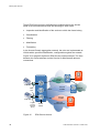
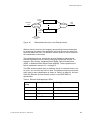
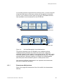
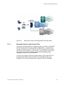
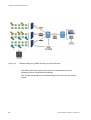
1
System Overview
EDA
System Overview
EDA
.
Copyright
© Ericsson AB - 2005 All Rights Reserved
Disclaimer
No part of this document may be reproduced in any form without the written
permission of the copyright owner.
The contents of this document are subject to revision without notice due to
continued progress in methodology, design and manufacturing. Ericsson shall
have no liability for any error or damage of any kind resulting from the use of
this document.
Trademark List
ii
Windows
Windows is a registered trademark of Microsoft
Corporation
Solaris
Solaris is a registered trademark of Sun Microsystems,
Inc.
Extreme Networks®
Extreme Networks is a registered trademark of Extreme
Networks, Inc.
Sybase®
Sybase is a registered trademark of Sybase Corporation
LSA-PLUS®
LSA-PLUS is a registered trademark of KRONE, Inc.
LSA-PROFIL®
LSA-PROFIL is a registered trademark of KRONE, Inc.
1/1551-HSC 901 35/3 Uen C 2005-12-02
.
Contents
1
Introduction to this Guide
1
1.1
Revision History
1
1.1.1
This revision (C)
1
1.1.2
Version B
1
1.1.3
Version A
1
2
The EDA Concept
2
2.1
ADSL Standards
3
2.2
The EDA System – Basic Principle
4
2.2.1
The IP DSLAM
5
2.2.2
The Aggregation Node
6
2.2.3
The EDA Management System
6
3
The EDA Access Network
8
3.1
The Access Domain
8
3.1.1
The Size of the Access Domain
8
3.1.2
Domain Subnets and IP Networks
9
3.1.3
The Domain Server
11
4
The EDA Components
13
4.1
The IP DSLAMs
13
4.1.1
The EDA Management Proxy (EMP)
15
4.1.2
EDA Solution without EMP
16
4.1.3
The EDN312 and EDN312x IP DSLAM
18
4.1.4
The EDN288 IP DSLAMs
19
4.1.5
The ECN Aggregation Node
22
4.2
The EDA Switches
26
4.3
The EDN424 HDSL IP DSLAM
30
4.4
Ethernet Power Nodes
32
4.5
The EDA Converters
33
1/1551-HSC 901 35/3 Uen C 2005-12-02
iii
Contents
iv
4.5.1
The FE to E1 and T1 Converter
33
4.5.2
Ethernet Gateway
34
4.6
Remote Powering
35
4.7
The EDA Subracks and Cabinets
37
5
Customer Premises Equipment
38
6
EDA System Services
40
6.1
The EDA Services
40
6.1.1
Bandwidth Control
44
6.1.2
CPE Access Methods
46
6.1.3
Transparent VLAN Service
46
6.2
Quality of Service
50
6.2.1
Traffic Classification
51
6.2.2
Traffic Handling
52
6.2.3
QoS Implementaion
54
6.2.4
QoS in IP Based Network Sections
54
6.2.5
Delay Imposed on Telephony over IP
54
6.3
QoS and Bandwith Control in the IP DSLAM
56
6.3.1
Downstream Mechanisms
57
6.3.2
Upstream Mechanisms
65
7
System Maintenance
68
8
Telephony and Multimedia Services
69
8.1
Baseband POTS and ISDN in EDA
70
8.1.1
Baseband Solution with Integrated Filter
70
8.1.2
Baseband Solution with External Filter
71
8.1.3
Baseband Solution with External ISDN Filter
72
8.2
Telephony over IP
73
8.2.1
Quality Considerations
75
8.2.2
Capacity
76
8.2.3
Security
76
1/1551-HSC 901 35/3 Uen C 2005-12-02
Contents
8.3
Multimedia Services
76
8.3.1
Quality
77
8.3.2
Security
77
8.4
Telephony Deployment in EDA
78
8.5
Broadcast Handling
78
8.6
Multicast Handling
79
9
Security
81
9.1
EDA Security Issues
81
9.2
PPP, VLAN and Forced Forwarding
82
9.2.1
PPP (Point to Point Protocol)
82
9.2.2
VLAN Technique
83
9.2.3
Forced Forwarding
85
9.3
DHCP Relay Agent Information Option
86
9.4
IP DSLAM Security Mechanisms
88
9.4.1
Filtering
88
9.4.2
Layer-2 Separation
89
9.5
Encryption and Tunneling
91
9.6
Other Security Measures
92
9.6.1
Management Security Policies
92
9.6.2
Network Monitoring and Intrusion Detection
92
10
EDA System Design
93
10.1
System Design Approach
93
10.2
Determining the EDA System Functions
94
10.2.1
Designing the Actual EDA System
95
10.3
EDA Scenario Examples
96
10.3.1
No Service Selection
96
10.3.2
Service Selection Using a BRAS
97
10.3.3
Service Selection Using VLAN
99
10.3.4
Service Selection by Using Domain Subnets
101
10.3.5
Service Selection using LAN-to-LAN Transparency
101
10.4
Dimensioning the Network
103
1/1551-HSC 901 35/3 Uen C 2005-12-02
v
Contents
10.4.1
Capacity of System Elements
103
10.4.2
Dimensioning an EDA Access Network
103
Glossary
vi
104
1/1551-HSC 901 35/3 Uen C 2005-12-02
Introduction to this Guide
1
Introduction to this Guide
This guide is intended to provide the reader with an overview of the EDA
system and concept. The guide describes the different elements forming an
EDA network, and how they interact in order to constitute a versatile and
flexible ADSL access network.
The guide may be read without prior knowledge of EDA and the
technologies used, but to fully understand the system function the reader
should be familiar with the basics of IP (Internet Protocol) technology.
The guide can be printed on a monochrome printer, but illustrations are
easier to understand if a color printer is used.
1.1
Revision History
The guide is valid for EDA 2.2 R2A. Other product versions, with functions
not described in this guide, may be available.
1.1.1
This revision (C)
The following changes have been made:
•
1.1.2
Minor changes section 4.2 on page 26.
Version B
The following changes have been made:
•
1.1.3
Line bonding description added.
Version A
This is the first version based on System Overview
1/1551-HSC901 35/2 Uen B. The following changes have been made:
•
ECN330 added.
•
Section 6 on page 40 rewritten.
•
New subrack solutions added
Version A was never publicly published.
1/1551-HSC 901 35/3 Uen C 2005-12-02
1
The EDA Concept
2
The EDA Concept
The EDA system can be tailored to a wide range of access scenarios,
depending on the actual requirements to function and performance.
Performance requirements are about for example the number of end-users
that the access system can handle, and the bandwidth allocated to the endusers. The functional requirements are more versatile, covering for
example which IP services to support, how to ensure security and privacy,
and how to provide options for service selection.
Both performance requirements and function requirements will often vary
significantly from one access scenario to another. Consequently, the EDA
system is designed to allow adaptation to almost any possible scenario.
The demand for broadband access to homes and small businesses is
rapidly increasing these years. Several technologies have been developed
to meet this demand - one technology is DSL (Digital Subscriber Line).
In DSL the telephony copper lines between end-users and the local
exchange are used for providing high-speed data access.
There are several types of DSL, characterized by a theoretical maximum
data rate offered to the individual end-users. Today, the most common type
is Asymmetric DSL (ADSL) in which the maximum data rates are
approximately 8 Mbps downstream (to the end-user), and 1 Mbps upstream
(from the end-user).
EDA is the product name for Ericsson’s ADSL access system. The concept
sets a new standard for implementing digital access systems in a fast,
flexible and future-proof way. EDA solves the major problems faced by
operators who want to go for mass-deployment of ADSL. These problems
include the relatively large number of man-hours required to install,
configure and manage traditional ADSL systems, the size and poor
scalability of these systems, and the growing requirements to provide
flexible unbundling of the local loop. The following summarizes the EDA
concept:
2
•
Complete ADSL concept providing Ethernet based access
•
Ultra compact DSLAM
•
Developed and optimized for easy deployment and maintenance
•
Adaptable to any broadband access scenario and penetration rate
•
Well suited for unbundling scenarios
1/1551-HSC 901 35/3 Uen C 2005-12-02
The EDA Concept
2.1
ADSL Standards
The EDA system supports the following ADSL standards:
•
ITU-T G992.1 Annex A (ADSL over POTS)
•
ITU-T G992.1 Annex B (ADSL over ISDN)
•
ITU-T G992.2 (ADSL Lite)
•
ITU-T G992.3 Annex A (ADSL2 over POTS)
•
ITU-T G992.3 Annex B (ADSL2 over ISDN)
•
ITU-T G992.3 Annex L (Extended Reach)
•
ITU-T G992.3 Annex M
•
ITU-T G992.5 (ADSL2+) Annex A and B
•
ITU-T G992.5 Annex L and M
Broadband Access over the Local Loop: Like traditional DSL systems
EDA provides broadband access over the local loop copper wires.
Traditional ADSL systems are based on a DSL access multiplexer
(DSLAM), which terminates the ADSL protocol layer towards the end-user.
The ATM connections running on top of the ADSL layer may be terminated
locally in an access node, or they may be conveyed over an ATM backbone
network to a remote Service Provider. New end-users obtain ADSL access
through individual wires drawn from their position in the main distribution
frame (MDF) to the DSLAM.
Transmission technology shift from ATM to Ethernet: With EDA the
main transmission technology is shifted from ATM to Ethernet. Compared
to ATM, the Ethernet technology is superior on important areas like
scalability, simplicity and equipment cost.
IP all the way: EDA deploys an “IP all the way” system supporting
integrated high-speed always-on triple play services (data, video and voice)
and supports more advanced services such as multicasting. EDA also
provides an innovative solution for base band telephony.
1/1551-HSC 901 35/3 Uen C 2005-12-02
3
The EDA Concept
2.2
The EDA System – Basic Principle
The basic principle of the EDA System is illustrated below in Figure 1 on
page 4.
The end-users are connected to the EDA network through the IP DSLAM.
The IP DSLAM is connected to an aggregation node, which provides layer2 Ethernet switching and subsequently connects the end-users to various
IP services through the EDA access network. The EDA system is managed
by the EDA Management System called Public Ethernet Management
(PEM).
The EDA system supports base band POTS, base band ISDN and
telephony over IP. Telephony over IP, and one base band telephony, either
POTS or ISDN, may coexist within a single EDA system and each end-user
can be allowed to access any of the applications, including all in parallel.
The EDA system can interface to any local exchange. The IP DSLAM
separates ADSL signals from base band signals, and base band signals
(telephony) are sent to the local exchange.
The EDA system can be extended to create different types of multi-service
network architectures. For example by adding a broadband remote access
server (BRAS), authentication, authorization and accounting (AAA) can be
provided. Please note that neither BRAS nor telephony over IP is part of
the EDA solution.
Figure 1
4
The EDA Concept Basic Principle
1/1551-HSC 901 35/3 Uen C 2005-12-02
The EDA Concept
2.2.1
The IP DSLAM
The IP DSLAM is the cornerstone in the EDA system.
It converts and aggregates all incoming ADSL subscriber lines into a 100
Mbps Ethernet connection and as opposed to a traditional DSLAM system,
the ATM layer in the ADSL protocol stack is terminated directly in the IP
DSLAM. By using link aggregation the subscriber lines can be increased to
200 Mbps connections.
To ensure high security for end-users and EDA equipment the IP DSLAMs
are capable of filtering the traffic in both upstream and downstream
direction.
The Ethernet based access function provided by the IP DSLAMs can be
extended to create different types of multi-service network architectures.
The EDA system is built around a number of different IP DSLAMS
described in more detail in section 4 on page 13.
2.2.1.1
Line Bonding
The IP DSLAM enables bonding of lines in order to provide high or very
high bandwidth to End-users. Line bonding is defining and using several
twisted pairs copper wires as a one line. Up to six lines can be bonded,
enabling a theoretical downstream bandwidth 132 Mbps. 44 Mbps can be
achieved with two bonded lines (1.5 km or less). Figure 2 on page 5
illustrates a comparison of line bandwidths using ADSL, ADSL2+ and two
bonded ADSL2+.
Bandwidth
(Mbps)
50
2 bonded ADSL2+ lines
40
ADSL2+
30
ADSL
20
10
1
Figure 2
1/1551-HSC 901 35/3 Uen C 2005-12-02
2
3
4
Reach (km)
Line Bonding Utilization
5
The EDA Concept
2.2.2
The Aggregation Node
As shown in Figure 1 on page 4 the IP DSLAMs are connected to an
aggregation node. Ethernet switches can be used as aggregation nodes
and provide the capability to increase the LAN bandwidth because they
allow for simultaneous switching of data packets between their ports.
Furthermore, an Ethernet switch may be able to perform more advanced
functions regarding traffic, such as prioritizing and separation.
A typical EDA switch used in an EDA system is the ESN310, which has 24
100 Mbps ports and two Gigabit Ethernet ports for the aggregated traffic
towards the edge node. The ESN310 has built-in power over Ethernet and
can thus supply the IP DSLAMS with –48 V power.
The Ethernet Controller Node and the EAN
Another type of aggregation node is the Ethernet Controller Node ECN,
which also provides layer-2 Ethernet switching with built-in power over
Ethernet, but has additional functions like automatic loading of software and
configuration data into the connected EDA nodes. The ECN has a built-in
node controller. It is a self-sustained IP DSLAM so to speak, composed of a
number of IP DSLAMs (EDN312) connected to the ECN330/ECN320 either
directly or through the EDA 8-port switch ESN108.
One of the key features of the EAN is the ability to act as a single node in
the EDA network, and all the “embedded” IP DSLAMs are added or
removed in a true plug-and-play way. The ECN330/ECN320 automatically
registers the nodes and their ports making implementation, expansion and
replacement of nodes very user-friendly and another advantage is, that
network elements are maintained by the ECN330/ECN320.
This means that the EAN does not depend on the Public Ethernet
Management system (PEM) when starting or restarting, and does not
depend on a Domain Server during normal operation, and furthermore
reduces the number of IP addresses necessary in the management
network.
The ECN330/ECN320 and the EAN are described in further detail in
section 4.1.4 on page 19.
2.2.3
The EDA Management System
The EDA management system provides the operator with a single
aggregated management platform for the complete EDA system.
The EDA management system is called Public Ethernet Management
(PEM). The management system is designed with scalability in mind, and
scales from a single server solution, where all parts of the system are
6
1/1551-HSC 901 35/3 Uen C 2005-12-02
The EDA Concept
running on a central computer, to a fully distributed solution where different
parts are deployed on multiple servers.
The Management Server contains the PEM servers and the database of
the EDA system. The database contains all end-user and network
configuration data. In a distributed configuration, the Management Server
acts as a central point for operation and maintenance, providing the full
view of the network.
PEM can be integrated through standard interface with an overlaying
management system.
The management system is described in further detail in section 8 on page
68.
1/1551-HSC 901 35/3 Uen C 2005-12-02
7
The EDA Access Network
3
The EDA Access Network
The main objective of the EDA system is to support provisioning of IP
services to end-users. The EDA system supports this through:
•
Network Access
•
Service Access
Network Access means providing access through the Access Domain.
Service Access means managing the end-users access to IP services.
The EDA system is mainly focused on providing network access, but it also
provides several integrated service access solutions. In this way, the EDA
system provides a complete IP service-enabling platform, which offers IP
services such as Telephony over IP and Video over IP.
3.1
The Access Domain
An EDA network is divided into geographically separated Access Domains,
as indicated in the principle illustration of the Access Network shown in
Figure 3 on page 9, showing an EDA system where the network has been
divided into three Access Domains. Each Access Domain is managed
locally and has an interface to an operation and maintenance center that is
the PEM. Furthermore the Access Domain has a Domain Server assigned
to it. The Domain Server can be present in the Access Network in a
physical sense but may also be installed on a Management Server.
Basically, the Access Domain is capable of conveying any network layer
protocol, but the Internet Protocol (IP) is thought of as the absolute
dominant layer-3 protocol used within EDA. The end-users can access IP
services offered by different providers at their Point-of-Presence (PoP)
through the backbone network.
The Ethernet within an Access Domain may span a single or multiple
physical sites.
3.1.1
The Size of the Access Domain
An Access Domain has no theoretical size limit, but the practical size limits
(due to IP DSLAMs start-up time, and limitations of the management
system), are as follows:
8
1/1551-HSC 901 35/3 Uen C 2005-12-02
The EDA Access Network
The EDA system network may have up to 20 Access Domains. Each
Access Domain can have up to 2,000 IP DSLAMs. The maximum number
of end-users in the EDA system network is approximately 1000,000.
If the number of end-users exceeds the maximum, multiple EDA systems
can be deployed.
Figure 3
3.1.2
The Access Network
Domain Subnets and IP Networks
The Access Domain comprises one or more IP Networks each defined by a
Network ID, a Subnet Mask and a Default Gateway, and comprises one or
more Domain Subnets, see Figure 4 on page 10.
Each IP Network in the Access Domain is divided into a number of Domain
Subnets. The Domain Subnet contains the network elements that are the
EDA nodes like IP DSLAMs, FE-E1 converters, and EDA switches.
An IP range is defined in each Domain Subnet for network elements, which
dynamically receives IP addresses from a DHCP Server. (Component of
the Domain Server), unless the EDA network is based on the Ethernet
Access Node (EAN), where the Domain Server function is an integrated
part of the ECN330/ECN320.
1/1551-HSC 901 35/3 Uen C 2005-12-02
9
The EDA Access Network
Figure 4
The Access Domain in the Access Network
The figure below shows that a Network ID, a Subnet Mask, and a Default
Gateway, identify an IP network in the Access Domain.
10
1/1551-HSC 901 35/3 Uen C 2005-12-02
The EDA Access Network
Figure 5
3.1.3
IP Network and Domain Subnets
The Domain Server
An Access Domain is a logical network handled by a management system
and defined by approved IP addresses. The components in an Access
Domain are managed by a Public Ethernet Management (PEM) system
through a Domain Server.
As shown in Figure 6 on page 12 the Domain Server is physically located in
the Access Domain or on the Management Server, but for an EAN, which is
shown to the right in Figure 6 on page 12, the Domain Server function is
integrated in the ECN330/ECN320 controller node.
The Domain Server comprises a DHCP server, a Domain File Server, an
NTP Server, PEM Domain Services, and HPOV clients.
1/1551-HSC 901 35/3 Uen C 2005-12-02
11
The EDA Access Network
Figure 6
The Access Domain and Domain Subnets
The Domain Server City 1 is responsible for all network nodes in the
Access Domain City 1.
The Domain Server for Access Domain City 2 is installed on the same
computer as the Management server. This will typically be the case when
the EAN is used as indicated in Figure 6 on page 12. Several Access
Domains is only necessary in EDA deployment scenarios where the EAN is
not used and the total number of end-users is high.
12
1/1551-HSC 901 35/3 Uen C 2005-12-02
The EDA Components
4
The EDA Components
The components of the EDA solution are described in further detail in the
following sections.
The nodes or components in an Access Domain are all connected to the
same Ethernet, which carries both end-user and management traffic. The
EDA system is built on the following components, which can be combined
to form a specific EDA solution:
•
IP DSLAMs - EDN312 and EDN288
•
Switches - ESN108, ESN310, ESN410 and ELN220
•
Ethernet Controller Node - ECN320 (An ESN310 with built-in EDA
Management Proxy (EMP) function) and ECN330 (A Layer 3 switch
with built-in EDA Management Proxy (EMP) function)
•
Subracks - Micro Subrack, Small Subrack, Medium 288 Subrack
•
Cabinets - Outdoor Cabinet
•
Converters - FE-E1 Converter (EXN104) and Ethernet Gateway
EXN401/410
•
Power Node - EPN102
•
Management system - Public Ethernet Management system (PEM)
The components are described in more detail in the following.
4.1
The IP DSLAMs
The EDA solutions are based on IP DSLAMs, which are available in a 12line, a 24-line version and a 288-line version. The IP DSLAMs are powered
over the Ethernet cables and both data and power is conveyed in the same
cable.
The IP DSLAMs can be aggregated in the network by using a 24-port
switch ESN310, without built-in EDA Management Proxy. The IP DSLAMs
can also be aggregated by the 24-port Ethernet Controller Node
(ECN330/ECN320), in which case the EDA Management Proxy is used.
1/1551-HSC 901 35/3 Uen C 2005-12-02
13
The EDA Components
As opposed to many traditional DSLAMs the IP DSLAM also terminates the
ATM layer used on top of the ADSL connections, thus interfacing directly to
the switched Ethernet within the Access Domain. The IP DSLAM bridges
between the switched Ethernet and the Ethernet at the customer premises,
see Figure 7 on page 14.
Figure 7
Bridging the Access Domain and the CPE Ethernet
The IP DSLAM terminates all end-user lines, and is able to provide high
speed IP access to all end-users simultaneously. Installing the IP DSLAM
at the Central Office, does not force the end-users connected to an IP
DSLAM to have ADSL, which means that service activation of ADSL is
done individually per subscriber line through the EDA Management System
(PEM).
On the local loop each end-user has up to eight ATM Permanent Virtual
Circuits (PVCs), depending on the CPE modem. Each PVC is individually
configured with a maximum bandwidth and can be used for different Quality
of Service scenarios.
The IP DSLAM is also able to make a Line Qualification Test in order to
estimate the ADSL connection properties. The Line Qualification Test can
be performed when the IP DSLAM is installed. The ADSL line does not
have to be activated in order to perform a Line Qualification Test.
The IP DSLAM has a built-in Over Voltage Protection (OVP), which
replaces the primary OVP typically mounted in the MDF and conforms to
ITU-T K.20 and ITU-T K.21.
When the IP DSLAMs are aggregated using a non-EMP switch the IP
DSLAMs are often referred to a stand-alone.
When the IP DSLAMs are aggregated using the EMP based
ECN330/ECN320 they are often referred to as embedded nodes.
14
1/1551-HSC 901 35/3 Uen C 2005-12-02
The EDA Components
In order to clarify the concept of a stand-alone and embedded IP DSLAM
the EMP and non-EMP solution is explained below.
4.1.1
The EDA Management Proxy (EMP)
EDA Management Proxy (EMP) is a built-in application in the Ethernet
Controller Node ECN330/ECN320. EMP removes dependency of PEM
servers during start-up and restart, and reduces the number of IP
addresses needed in the management network as it defines the
ECN330/ECN320 and its connected network elements as one logical node
named Ethernet Access Node (EAN).
Figure 8
Example of an EAN
The EAN above shows a number of network elements connected to an
ECN330/ECN320. The local IP addresses of the network elements are not
visible in the management network, except for the IP address of the
Ethernet Controller Node. The ECN330/ECN320 maintains the connected
network elements using local IP addresses.
1/1551-HSC 901 35/3 Uen C 2005-12-02
15
The EDA Components
EMP makes the ECN330/ENC320 appear as one large IP DSLAM with one
static IP address and up to 2016 end-users. This number of lines can be
reached, if all ECN330/ECN320 downlink ports are used for aggregation of
ESN108 switches, and the ESN108 switches each employ 7 electrical
downlink ports, and if the EDN312 IP DSLAMs are used entirely. If the
EDN312 IP DSLAMs are connected directly to the downlink ports of the
ECN330/ECN320, then 288 ADSL lines will be available. This solution is
achieved with the EDN288, which is described later. The EDN288 is
referred to as an 288-lines IP DSLAM but should be thought of as an EAN
with EDN312 IP DSLAMs.
The ECN320 benefits from automatic registration of all connected network
elements and their ports, thus making implementation, expansion and
replacement of nodes very user-friendly. Another advantage is, that
network elements are maintained by their local EMP and do not depend on
a Domain Server during normal operation.
The Domain Server is only used by the EAN for software upgrade,
synchronization, and for SNMP commands.
The network elements are loaded with application software and a
configuration file from the EMP. The load is done locally and not from the
PEM management system, thus reducing management traffic in the
network.
Characteristics of an aggregation node with EMP:
4.1.2
•
Auto-registration of network elements
•
Network element software and configuration files are distributed to the
EMP
•
One IP address per aggregation node
EDA Solution without EMP
The figure below, see Figure 9 on page 17, shows four IP DSLAMs and
one 8-port Ethernet switch (ESN108) connected to an ESN310, which is an
Ethernet switch without EMP. All six IP addresses of the network elements
are visible to the management network and all six elements are maintained
individually from PEM.
Each network element is registered manually in PEM.
The Ethernet switch ESN310 aggregates traffic in the Access Domain. The
PEM Domain Server provides network elements in the Access Domain with
application software and configuration data. The Domain Server is also
responsible for alarm handling and network topology discovery.
16
1/1551-HSC 901 35/3 Uen C 2005-12-02
The EDA Components
The Domain Server co-operates with the Management Server, thus
creating a distributed management system. SNMP trap filtering in the
Domain Server reduces management traffic towards the Management
Server. Automatic discovery of nodes in the Access Domain by the local
Domain Server is another advantage of a distributed management system.
The number of maintenance IP addresses in the Access Domain can be
quite high because every network element has its own IP address. The
maximum number of maintained IP addresses per Domain Server is 2000.
Characteristics of an aggregation node without EMP:
•
Manual registration of network elements
•
Application software and configuration files are loaded from the Domain
Server
•
Discovery and trap filtering by the Domain Server
•
Many IP Addresses in each Access Domain
Figure 9
1/1551-HSC 901 35/3 Uen C 2005-12-02
Solution without EAN
17
The EDA Components
4.1.3
The EDN312 and EDN312x IP DSLAM
The 12-line IP DSLAM comes in two version, the EDN312 and the
EDN312x both and available in different variants
•
EDN312p – 12 lines with built-in POTS filter
•
EDN312i – 12 lines with built-in ISDN filter
•
EDN312e – 12 lines with built-in POTS filter and complies to ETSI
standard.
•
EDN312xp – 12 lines with built-in POTS filter, ADSL2+ facilities and
two 100 Mbps Ethernet uplink ports, making it possible to use them in a
link aggregation scenario.
•
EDN312xi - 12 lines with built-in ISDN filter, ADSL2+ facilities and two
100 Mbps Ethernet uplink ports, making it possible to use them in a link
aggregation scenario.
•
EDN312xe – 12 lines with built-in POTS filter, ADSL2+ facilities and
two 100 Mbps Ethernet uplink ports, making it possible to use them in a
link aggregation scenario. Complies to the ETSI standard.
Redundancy and Aggregation Options (EDN312x only)
The EDN312x versions (EDN312xp, EDN312xi and EDN312xe) have two
uplink ports, which EAN redundancy, and EDN312x link aggregation. EAN
redundancy utilizes Rapid Spanning Tree, which can be setup in the
ECN320. The two scenarios are described in further detail below in section
4.1.4 on page 19, but for a full understanding the reader is referred to the
EDN288 User Guide.
There is no difference between the two uplink ports of the EDN312x. It
does not matter which port is connected to which aggregation switch. The
EDN312x draws power from one of the links. There is no indication and it is
not possible to know which link supplies the power (applies also to the
redundancy scenario).
Note:
18
If the link that currently supplies the EDN312x is disconnected, or
the power fails, the EDN312x will restart and draw power from the
other link.
1/1551-HSC 901 35/3 Uen C 2005-12-02
The EDA Components
4.1.4
The EDN288 IP DSLAMs
With the 288-lines IP DSLAM Ericsson introduces the new and important
concept of the Ethernet Access Node (EAN). In order to understand the
function of the EDN288 it is important to understand the EAN concept,
therefore the EAN is described in detail in the following.
The EDN288
The EDN288 is an EAN node, and available in the variant EDN288p and
EDN288xp.
Figure 10
The 288-line IP DSLAM - EDN288
The EDN288p is a complete all-in-one system for 288 lines and consists of
24 12-lines EDN312p IP DSLAMs and an Ethernet Controller Node
(ECN330/ECN320) fully cabled and assembled in a subrack prepared for
installation in a standard 19” or ETSI cabinet, see Figure 10 on page 19.
The EDN288xp is similar to the EDN288p but supplied with 24 12-lines
EDN312xp IP DSLAMs.
Furthermore the EDN288xp can be extended with an extra
ECN330/ECN320, which makes it possible to enable EAN redundancy or
link aggregation, depending on how cabling is performed. This is explained
in more detail below.
1/1551-HSC 901 35/3 Uen C 2005-12-02
19
The EDA Components
EAN Redundancy
EAN redundancy is ensured by connecting the two Ethernet ports of the IP
DSLAM to each ECN330/ECN320, as illustrated in Figure 11 on page 20.
Redundancy requires enabling of Rapid Spanning Tree (RSTP) in both of
the ECN330/ECN320.
Figure 11
Cabling of Ethernet Cables for EAN Redundancy
EDN312x Link Aggregation
The two ports of the IP DSLAM can also be used to enable link bandwidth
of 200 Mbps to a single EDN312x.
20
1/1551-HSC 901 35/3 Uen C 2005-12-02
The EDA Components
Figure 12
EDN312 Link Aggregation
Two ports of the ECN330/ECN320 can be joined to form one aggregated
link. This is also called a trunk. By trunking two ports, the speed can be
increased to 200 Mbps. The two uplink ports can also be grouped. There is
a limitation though because the ECN330/ECN320 only supports up to 6
aggregated links.
This means that if the two uplink ports are grouped, only 5 downlink trunks
can be created. If the extended EDN288x is cabled and configured to
utilize the maximum number of aggregated links, this will result in two EANs
with 144 end-user connections each (72 aggregated and 72 normal).
Connecting the single uplink IP DSLAMs to two ports will ensure PoE
redundancy, as well as easy change of the aggregated devices without the
need of changing the cabling on site.
When a link aggregation is selected as the link type of an EDN312x in
PEM, both Ethernet connections will automatically be activated. As
previously mentioned it is not possible to select more than six aggregated
links for a single ECN330/ECN320.
The cabling is illustrated below in Figure 13 on page 22. The illustration
shows how the IP DSLAMs in the upper row of the EDN288x are connected
to the ECN330/ECN320. The IP DSLAMs in the lower row are connected to
the lower ECN330/ECN320 the same way.
1/1551-HSC 901 35/3 Uen C 2005-12-02
21
The EDA Components
Figure 13
4.1.5
Cabling of Ethernet Cables for Link and PoE Redundancy
The ECN Aggregation Node
The heart of an EAN is a node controller, the Ethernet Node Controller,
which is an integrated part of the ECN330/ECN320, which also functions as
a 24 ports Ethernet switch.
22
1/1551-HSC 901 35/3 Uen C 2005-12-02
The EDA Components
Figure 14
The Ethernet Controller Node - ECN320
The switch part has Power over Ethernet capabilities and apart from the
controller IP DSLAMs (EDN312), and ESN108 can be connected to it to
form an EAN. Furthermore the optical switch ELN220 can be connected to
it in order to support small remote sites using fiber optical connections. The
embedded nodes may be installed as and when desired.
The Ethernet Node Controller of the ECN330/ECN320 manages all the
embedded nodes. From a management point of view, the switch is also an
embedded element, even though it is located and integrated in the
ECN330/ECN320. All management of the embedded nodes is done
through the Ethernet Node Controller, which is the only element
communicating directly with the Public Ethernet Manager (PEM).
Using the EDA Management Proxy (EMP) function as described previously
in section 4.1.1 on page 15, the Ethernet Node Controller forwards the
communication to and from the embedded nodes. Note that only the
management traffic goes through the Ethernet Node Controller. The enduser traffic is unaffected by the EAN structure.
The Ethernet Node Controller handles all functions of the Access Domain
Server for the embedded nodes. Therefore the embedded nodes does not
depend on the Access Domain Server, but the Access Domain Server must
be running for the following reasons:
1. All communication with the ECN is SNMP based.
2. The Ethernet Node Controller gets new SW applications for the ECN
from the Domain File Server when SW upgrade is performed.
3. The Ethernet Node Controller gets SW applications and configurations
for the embedded nodes from the Domain File Server when the EAN is
synchronized from PEM.
1/1551-HSC 901 35/3 Uen C 2005-12-02
23
The EDA Components
Figure 15
Ethernet Access Node Structure
The ECN320 contains 24 10BASE-T/100BASE-TX RJ-45 ports and two
combo ports—10/100/1000BASE-T ports which operate in combination with
Small Form Factor Pluggable (SFP) transceiver slots.
The ECN330 contains 24 10BASE-T/100BASE-TX RJ-45 ports and two
combo ports—10/100/1000BASE-T ports which operate in combination with
Small Form Factor Pluggable (SFP) transceiver slots and an additional
electrical 10/100/1000BASE-T port.
The ECN330/ECN320 is used as the first and second level aggregation
switch in the EDA network (second level with ESN108 or ELN220 as first
level), while also supplying IP DSLAMs with DC power over the Ethernet
connections.
It has two power supply ports which establishes power redundancy.
As well as its Power-over-Ethernet capabilities, the ECN320 provides
comprehensive network management features, such as, multicast
switching, virtual LANs, and Layer 2/3/4 CoS services that provide reliability
and consistent performance for network traffic.
24
1/1551-HSC 901 35/3 Uen C 2005-12-02
The EDA Components
ECN330 looks very similar to ECN320, but ECN330 is built on an improved
hardware platform supporting a number of advanced features like 4k VLAN,
16k MAC table, full link aggregation, and Layer 3 routing.
ECN330 also supports Layer 2 MPLS for tunneling and a number of
redundancy protocols, e.g. Rapid Spanning Tree Protocol (RSTP), Multiple
Spanning Tree Protocol (MSTP) and Ethernet Automatic Protection
Switching (EAPS).
1/1551-HSC 901 35/3 Uen C 2005-12-02
25
The EDA Components
4.2
The EDA Switches
The EDA solution offers a suite of switches - two 1st level aggregation
Ethernet switches (ESN108 and ESN310) with integrated Power over
Ethernet functionality for powering the IP DSLAMs, and one 2nd level optical
aggregation Ethernet switch (ELN220).
The ESN108 Switch
For small sites in areas with low subscriber density the EDA Ethernet
switch, ESN108, fits very well, see Figure 16 on page 27.
The modularity of the switch is optimal for small sites with up to 96 lines
and thus fits perfectly with a small pre-cables solution containing eight 12port IP DSLAMs and one ESN108 aggregation switch for traffic uplink, see
section 4.7 on page 37.
The switch offers 8-ports 100 Mbps Fast Ethernet downlink and 1 optical
100/1000Mbps Mbps aggregate (uplink) port. It has built in Power over
Ethernet (PoE) used for distributing the power to the connected IP DSLAM
through the downlink ports.
The ESN108 offers multicast loading of IP DSLAM software and multicast
video streaming by use of IGMP snooping. Listening to Internet Group
Management Protocol (IGMP) messages it builds mapping tables and
associates forwarding filters. It dynamically configures the switch ports to
forward multicast traffic only to those ports associated with multicast hosts.
The switch also offers port mapping filtering and is transparent for VLAN
IDs. It is managed by the Public Ethernet Manager (PEM).
26
1/1551-HSC 901 35/3 Uen C 2005-12-02
The EDA Components
Figure 16
EDA Ethernet Switch (8 ports) with PoE - ESN108
The ESN310 Switch
The ESN310 is a switch specially designed for the EDA solution, see
Figure 17 on page 27. The switch offers 24 ports 100 Mbps Fast Ethernet
downlink ports. The uplink ports can be either 2 Gigabit (10/100/1000) Fast
Ethernet ports or 2 Gigabit optical ports.
It has built in Power over Ethernet (PoE) and can be managed by the PEM.
The switch supports multicast loading of IP DSLAM software and multicast
video streaming by use of IGMP snooping.
Figure 17
1/1551-HSC 901 35/3 Uen C 2005-12-02
EDA Ethernet Switch (24 ports) with PoE - ESN310
27
The EDA Components
The ELN220 Switch
The ELN220 switch shown in Figure 18 on page 28, is a 2nd level
aggregation switch offering 24 optical ports for aggregation of the ESN108
and ESN310.
It has 2 Gigabit Ethernet uplink ports, and can be managed through PEM.
The ELN220 can be used as an embedded node in an EAN and is then
connected to the optical uplink port-25 of the ECN320. The main purpose is
to support small remote sites through fiber optical connections.
The scenario is illustrated below in Figure 19 on page 29.
Figure 18
Ethernet Switch (24 optical ports - ELN220)
The purpose of the ELN220 switch is to support small remote sites through
fiber optical connections. The ELN220 switch has 24 optical ports, which
can be connected to the optical uplink port of the 8-port ESN108 switch.
This means that up to 24 ESN108 switches can be connected to the
ELN220, thus making it possible to support up to 24x8x12=2304 remote
end-users.
As indicated by the illustration in Figure 19 on page 29 the 12-line IP
DSLAM EDN312 is used in this scenario. The ECN320 has 24 downlink
ports, which can be connected to for example 24 12-lines IP DSLAMs
locally and thus the total supported end-users will be extended with 288
local end-users.
28
1/1551-HSC 901 35/3 Uen C 2005-12-02
The EDA Components
Figure 19
The ELN220 as an Embedded Node in the EAN
The ESN410 Switch
The ESN410 is a layer-3 Gigabit aggregation switch for the EDA solution,
primary for network configurations that require some type of routing
functionality. This means that it supports IP routing with the ability of routing
at layer-3. Furthermore it has comprehensive network management
functions such as Spanning tree protocol for standard bridging, GVRP for
VLAN configuration, SNMP, RMON and Web management.
The switch is seen as a second level aggregation switch for the ECN320
and the ESN310. It has 12 1000Mbps ports, 4 of which are Ethernet combo
ports for either RJ-45 cables or connection to fiber cables through a SFP
connector.
The switch is manageable through a Command Line Interface (CLI) and
through SNMP.
1/1551-HSC 901 35/3 Uen C 2005-12-02
29
The EDA Components
The ESN410 is prepared for 19” rack mounting and has built-in fan units
that can be replaced without service interception.
Figure 20
4.3
The ESN410 Layer-3 Gigabit Switch
The EDN424 HDSL IP DSLAM
The EDN424 is a 24-port IP DSLAM in the EDA solution. EDN424 is an
environmental hardened, 1U high mini-DSLAM that aggregates 24 SHDSL
lines to one 100 Mbps Ethernet. Design flexibility enables the EDN424 to
be mounted as rack, wall or vertical positioned units inside an existing
closure.
Downlink and Uplink ports
EDN424 offers 24 SHDSL downlink ports, each supporting symmetrical
bandwidth of up to 2.3 Mbps for single pairs and 4.6 Mbps in 4-wire mode.
Future upgrade will enable 5.7 Mbps per pair according to SHDSL.bis. The
uplink aggregates the 24 ports to 100 Mbps Ethernet. Management.
The Public Ethernet Manager (PEM) is the element manager for EDN424.
A customized management VLAN is terminated in the EDN424 to enable
remote management of the unit. The northbound interface of PEM offers
generic interfaces, such as CORBA and SNMP, enabling use of the same
provisioning and management system already employed in the operator’s
network.
Services
EDN424 enables the operator to offer a wide range of services:
30
•
Telephony over IP (ToIP) to the end-users
•
Data services as either fixed bandwidth or bandwidth on demand, with
the possibility of using the existing PPP authentication
1/1551-HSC 901 35/3 Uen C 2005-12-02
The EDA Components
•
Small Medium Enterprise (SME) services, such as video conferencing,
LAN to LAN, VPN services to the enterprise over the existing copper
The SHDSL loops provide flexibility in the deployment schemes. The loops
can be delivered individually in single port SHDSL customer premises.
Other deployment options include 4-wire mode for longer reach or higher
bandwidth.
Security
EDN424 ensures a secure network by offering VLAN according to IEEE
802.1Q. In future upgrades of EDN424 it will be possible to form up to 12
IMA groups with 2 to 18 ports per group. This feature makes it possible to
differentiate the service by offering different symmetrical bandwidths up to
more than 40 Mbps. Up to eighteen copper pairs are required to offer this
service.
Ethernet DSL Access
Figure 21
1/1551-HSC 901 35/3 Uen C 2005-12-02
The EDN424 HDSL IP DSLAM
31
The EDA Components
4.4
Ethernet Power Nodes
For EDA solutions where the IP DSLAMs are not powered by an EDA
switch or where a Fast Ethernet to E1 converter is used, Ethernet Power
Nodes can be applied. The Ethernet Power Node is available, EPN102,
Figure 22 on page 32.
The Ethernet Power Node, EPN102, is able to supply two devices with
power, but only one IP DSLAM. It is used for small sites for powering an IP
DSLAM and a Fast Ethernet to E1 converter (FE-E1). A typical scenario is
shown in Figure 24 on page 34.
Figure 22
32
Ethernet Power Node - EPN102
1/1551-HSC 901 35/3 Uen C 2005-12-02
The EDA Components
4.5
The EDA Converters
For small site solutions the EDA system offers two types of converters, the
FE to E1 converter (EXN104) and the Ethernet gateway (EXN401/410) for
bridging the Ethernet and the ATM network.
4.5.1
The FE to E1 and T1 Converter
The Fast Ethernet to E1 converter (EXN104) is a small-managed converter
developed for EDA rollout where no Ethernet uplink is available, see Figure
23 on page 33. The FE-E1 converter is intended for installation of the EDA
solution at small sites with a few IP DSLAMs, see Figure 24 on page 34.
Figure 23
Fast Ethernet to E1 and T1 Converter - EXN104
A cost-effective solution to this problem is to transport the Ethernet traffic
through vacant E1 lines using the FE-E1 converter. For a small site either
remote or at the CO the typical PoE box is an EPN102.
Furthermore the converter can be setup to transport the Ethernet traffic
through T1 lines. The converter is default setup to run in E1 mode, but can
be configured to run in T1 mode as well. One important difference between
running E1 and T1 is the data transfer speed, which for an E1 line is 2.048
Mbps and for a T1 line is 1.544 Mbps.
1/1551-HSC 901 35/3 Uen C 2005-12-02
33
The EDA Components
Figure 24
4.5.2
Fast Ethernet to E1 or T1 Converter in a Small Site Solution
Ethernet Gateway
The EXN401/410 is a small 1U easy-installable Ethernet to ATM STM-1
gateway developed to facilitate re-use of existing legacy ATM core
networks. Ethernet traffic from a Fast or Gigabit port is encapsulated
according to RFC2684 bridged mode onto ATM AAL5 PVCs according to
traditional ATM DSLAM installations, see Figure 26 on page 35.
EXN401/410 provides a unique possibility to implement Ethernet-based
broadband access networks while re-using the existing ATM core
infrastructure such as ATM core interfaces and routers.
The EXN401/410 series supports the migration of broadband access
networks from traditional ATM over SDH/Sonet to cost-efficient Ethernet,
while preserving the quality of service and service availability.
Figure 25
34
The Ethernet Gateway EXN401/410
1/1551-HSC 901 35/3 Uen C 2005-12-02
The EDA Components
Figure 26
4.6
Migration from Ethernet to ATM through EXN401/410
Remote Powering
Remote powering is a concept for distributing DC power over existing
twisted pairs. Remote powering is typically used in broadband applications,
where telecom equipment located close to the end-user requires power.
What makes remote powering attractive is the independence of local power
utilities and centralized back-up systems (batteries). The system consists of
a Remote Power System at the Central Office and a converter at the
Remote Site. The design of the system is based on safety standards IEC
60950-21, IEC 60950-1, and GR 10989-CORE.
At the Central Office the Flatpack Remote Power Systems are designed for
remote powering of telecom equipment, and provide ±190 V DC from a 48
V DC source. The power system consists of a 2HU Flatpack Mini PRS
chassis, 19” or 21” (ETSI) wide. This chassis houses up to two DC/DC
converters and VA limiters (24 channels).
1/1551-HSC 901 35/3 Uen C 2005-12-02
35
The EDA Components
Central Office
Remote site
Flatpack
Remote Power System
Remote Unit
I [mA]
190V-380V/48V
DC/DC Converters
Line impedance
[Ohm]
VA limit
VA limit
DC/DC
converter
-48 to
±190
+190
Vremote
[V]
Vco
[V]
1
48V to DSLAM
1
GND
-190
Cable length
[m, km, kft]
5
12
VA limit
Figure 27
Block diagram for the remote powering
Figure 27 on page 36 shows a block diagram of the remote powering
system.
The DC/DC converter is a 1500-watt step up converter which provides
±190 V DC from a traditional –48 V DC source. The VA limiter distributes
the ±190 V DC and provides a safe power distribution over existing twisted
pairs, protecting the Remote Feeding Circuits (RFT) from over-voltage,
over-current, and leakage current to ground. The VA limiter has 12
individual outputs of up to 100 W each (RFT-V).
The converters at the remote site consist of parallel DC/DC converters that
terminate the twisted pairs being fed from the Central Office. The
converters incorporate high-energy surge protection and one specifically
designed to work with a limited power source (VA limiter) and fed over a
high-impedance line. The modules can be paralleled to meet the power
requirement at the Remote End.
36
1/1551-HSC 901 35/3 Uen C 2005-12-02
The EDA Components
4.7
The EDA Subracks and Cabinets
Subracks are available in various sizes and configurations adapted for
different solutions. An overview of available pre-cabled subracks and
cabinets is shown below in Table 1 on page 37.
Table 1
Overview of Subracks and Cabinets
Name
Description
Subrack/36
Subrack based on 2x12-line IP DSLAMs and the 8
port switch (ESN108)
12-36
Subrack/96
Subrack with 8x12-line IP DSLAMs and one 8-port
switch
96
Subrack/144
Subrack with 12x12-line IP DSLAMs and one 24-port
Ethernet Controller Node (ECN330)
144
Subrack/288
2 rows with each 12x12-lines IP DSLAMs and one
24-port switch (ESN310) or an Ethernet Controller
Node (ECN320 or ECN330) with EDGE plugs
288
Outdoor
Cabinet
8x12-lines IP DSLAMs and one 8-port switch
(ESN108)
96
1/1551-HSC 901 35/3 Uen C 2005-12-02
Capacity/
end-users
37
Customer Premises Equipment
5
Customer Premises Equipment
The termination of the ADSL connection at the customer premises may be
performed in various ways, depending on the type of access protocol and
the customer’s type of equipment. Since EDA is based on Ethernet, some
part of the Customer Premises Equipment (CPE) must provide termination
of this layer.
The following possibilities exists:
1. The Access Domain Ethernet may be bridged by the modem towards a
local physical Ethernet. The modem terminates the ADSL and ATM
layers. Hosts are connected to the modem via the local Ethernet.
2. The Access Domain Ethernet (and lower layers) may be terminated by
the modem, turning it into a combined ADSL modem and IP router.
Typically, hosts are connected to the router via Ethernet.
3. The modem may terminate only the ADSL layer, and convey the
Access Domain Ethernet and ATM layers over USB towards the host.
Thus the Ethernet layer is emulated within the host.
The CPE equipment protocol termination is shown in Figure 29 on page 39.
The EDA concept is able to operate with any standard CPE modem
complying with the ADSL standards. In Figure 28 on page 38 a CPE
modem from Ericsson is shown: The HM310dp is an efficient and highperforming broadband router, using the ADSL2 Annex M technology.
Figure 28
38
Ericsson Modem HM310
1/1551-HSC 901 35/3 Uen C 2005-12-02
Customer Premises Equipment
Figure 29
CPE Equipment Protocol Termination
Some ADSL modems are able to operate in either bridged or routed mode.
A bridging modem requires a minimum of configuration, but does not
provide any security for hosts connected through it.
A routing modem, on the other hand, often provides means for enhancing
the security, for example by firewall and NAT function. If telephony is
required, the CPE should provide a POTS interface to legacy telephones.
1/1551-HSC 901 35/3 Uen C 2005-12-02
39
EDA System Services
6
EDA System Services
EDA is a versatile and flexible system, and can be designed to fit various
requirements regarding service access, network architecture, and network
performance. Furthermore the EDA system solution can be adapted to
various requirements regarding scalability and redundancy.
This section gives an overview of the services that can be provided by the
EDA system.
6.1
The EDA Services
An EDA Service is a set of rules and properties, which defines how traffic is
handled to and from an End-user through the aggregation network. A
Service always has a Service Identifier that defines how to identify traffic of
the specific Service.
The EDA Service should not be confused with a service offered by Service
Providers as for example Internet connection, IP Telephony, IP video
services and so on. The EDA Service defines properties such as
associated VLAN, PVC, CPE Access Method and more. Thus the Service
Provider provides the contents of the service, while the EDA Service
provides the means to access the contents, with a defined bandwidth. The
Quality of Service is the part of the rules, which defines the desired
transport quality with respect to for example packet loss and delay.
The rules are applied to each frame, thus enabling the End-user to reach
specific Service gateways or servers, and with the desired quality.
A key requirement of an access network is to impose service access
constraints, that is, ensure that access is allowed only to services for
which the End-user is authorized. In traditional broadband access network,
this task is ensured by a Broadband Remote Access Server (BRAS). The
BRAS is a single node through which all traffic must flow. The BRAS is
located at the border between the aggregation network and the application
servers or external network like the Internet.
40
1/1551-HSC 901 35/3 Uen C 2005-12-02
EDA System Services
Figure 30 on page 41 depicts a traditional access network scenario, where
a BRAS controls what End-users can access. The aggregation network in
itself imposes no constraints, but only transport all the End-user traffic to
and from the BRAS.
Application
Server
Access
Node
IP Network
Access
Node
Access
Node
Local loop
Figure 30
BRAS
Aggregation
network
Application
Server
Traditional BRAS Controlled Access
Figure 31 on page 41 illustrates a multiple edge access network scenario.
In this scenario it is the access nodes and aggregation network that must
impose the restrictions on the End-user traffic.
Access
Node
Application
Server
IP Network
Access
Node
Access
Node
Local loop
Figure 31
1/1551-HSC 901 35/3 Uen C 2005-12-02
Gateway
Aggregation
network
Application
Server
Multiple Edge Access
41
EDA System Services
These EDA Service rules or definitions are implemented in the Access
Node as a virtual switch that does the following on each frame:
•
Inspection and identification of the service to which the frame belong
•
Classification
•
Filtering
•
Modification
•
Forwarding
In the Access Domain aggregation network, the rules are implemented as
VLANs with a specified classification, configured throughout the network.
Figure 32 on page 42 depicts an EDA Service Access example. The lines
between the virtual switches and the Service VLANs illustrate allowed
connections.
Access Node
Application
Server
Service
VLAN 1
BRAS
End-user
Service
VLAN 2
ADSL
layer
Router
Service
VLAN 3
End-user
Logical
Access
Channel
(PVC)
Figure 32
42
Internet
Virtual
switch
Ethernet
Access Domain
Application
Server
EDA Service Access
1/1551-HSC 901 35/3 Uen C 2005-12-02
EDA System Services
As Figure 32 illustrates, EDA Access network support both BRAS and
multiple edge access scenario. The basic service identifier is a PVC
(denoted as logical access channel in Figure 32). A virtual switch controls
the traffic for each PVC in the network. It is important here to remark that
the virtual switch is automatically configured when a service is assigned to
an End-user. The Service VLAN1 in Figure 32 illustrates an EDA Service
that contains two provider services that might have different QoS demands.
The Ethernet in the Access Domain is capable of treating different frames
with different QoS classification differently. The EDA Service allows for
different CoS (Class of Service) flows with different QoS through the same
PVC thus ensuring differential treatment of traffic through the DSL
connection even if only one PVC is used.
A Service VLAN can also be used to create layer-2 connections to other
End-users, either locally or across a transport network, creating a
Transparent LAN Service (TLS).
The traffic to the End-user is identified by the PVC that it came from or was
destined to. Since a Service VLAN is a property of the Service, there is a
one to one traffic mapping between PVC and VLAN. However, it is also
possible to add a parameter to the PVC as the Service identifier. It is
possible to use Ethertype information and to create a service where the
traffic from one PVC is mapped to two VLANs (and two gateways)
according to the Ethertype (PPP or IP). Figure 33 on page 43 illustrates this
scenario.
Traffic
Ethertype:
PPP
Service VLAN 1 BRAS
PPP
Internet
IP
Traffic
Ethertype:
IP
Service VLAN 2
Application
Server
Access Node
Figure 33
1/1551-HSC 901 35/3 Uen C 2005-12-02
Traffic Mapping to Two VLANs
43
EDA System Services
In practice, this scenario is done by creating two Service Configurations,
and using the same PVC for both.
6.1.1
Bandwidth Control
The bandwidth control in EDA is done in several layers:
1. The DSL layer by setting the overall bandwidth for the DSL connection
2. The ATM layer by setting the bandwidth for each PVC
3. The Ethernet layer by applying traffic policing
Figure 34 on page 44 illustrates an example of the bandwidth control
principle.
Service
2
Service
3
Service DSL:
1
13184/1216 kbps
IAD
Access Domain
Ethernet
4 PVCs
Service
4
Service
VLAN 3
PVC1: Service 1, Telephony 384/384 kbps
PVC2: Service 2, Data 8192/256 kbps
Service
VLAN 1
Service
VLAN 4
Router/
BRAS
PVC3: Service 3, Video 4096/64 kbps
PVC4: Service 4, LAN to LAN 512/512 kbps
Flow
2
Total bandwidth all PVCs: 13184/1216 kbps
DSL:
12288/640 kbps
1 PVC
Flow
2
Flow
1
Service
VLAN 2
IP
DSLAM
End-user 1
Video
Server
Voice
Gateway
Internet
Flow 1
Ethernet
Switch
DSL
CPE
PVC1 needs:
Flow 1: Service 2, Video 4096/128 kbps
Flow 2 : Service 2, Data 8192/512 kbps
End-user 2
Figure 34
44
Total bandwidth PVC 1: 12288/640 kbps
Bandwidth Control with Services
1/1551-HSC 901 35/3 Uen C 2005-12-02
EDA System Services
Two End-users are shown in Figure 34 on page 44. The DSL configuration
is set for the total bandwidth of the entire customer services combined.
End-user 1 has four EDA Services, which gives a total bandwidth demand
of 13184 kbps downstream, and 1216 kbps upstream. The bandwidth for
each PVC is set individually, and the DSL bandwidth is set to the total
amount of all PVCs bandwidths together.
End-user 2 has one EDA service (single PVC) that contains two CoS flows:
high priority for video and low priority for data. The bandwidth needs for the
PVC is 12288 kbps downstream and 640 kbps upstream. It is not possible
to configure the bandwidth of each CoS flow individually.
The DSL bandwidth can also be set to less than the sum of the services
bandwidth. In this case, the bandwidth of the services will decrease
according to the priority of each service, when simultaneously used
services demand more than the available DSL bandwidth.
The control of the upstream bandwidth for each service should be done by
the CPE modem. The IP DSLAM supports Integrated Local Management
Interface (ILMI) for the configuration of the CPE modem. If the CPE modem
does not support ILMI, the IP DSLAM can force upstream policing. No
matter how the CPE modem is configured, the total upstream bandwidth
can never exceed the DSL upstream bandwidth.
The bandwidth of the EDA Services can be changed on the fly. In order to
be able to do that, the DSL bandwidth must be set to the highest requested
bandwidth. That means that there might be situations where the DSL
bandwidth is larger than the sum of all the PVCs bandwidths. If there is no
total control over the configuration of the CPE modem PVC upstream
bandwidth, it is possible to impose policing in the Ethernet layer in the IP
DSLAM. The policing can be imposed per PVC, CoS flow or both. Please
note that policing, unlike shaping, discards packets if the specified
bandwidth is exceeded even in short periods.
1/1551-HSC 901 35/3 Uen C 2005-12-02
45
EDA System Services
6.1.2
CPE Access Methods
When the End-user is to receive an IP based service, the Customer
Premises Equipment (CPE) must be configured with IP settings such as IP
address, subnet mask and default gateway. The way in which the
equipment receives these settings is called Access Method. The Access
Method is an attribute of an EDA Service, and when the Service is
assigned to an End-user, the CPE can only use that specific Access
Method. The following Access Methods can be used:
6.1.3
•
DHCP - Dynamic Host Configuration Protocol, which means that the IP
address of the CPE is set dynamically by the Service Broker’s DHCP
server.
•
Static IP address - The CPE equipment is assigned a static IP address
or IP address range (that is, DHCP or PPP cannot be used).
•
Transparent LAN – When LAN-to-LAN transparency is used, all filtering
in the IP DSLAM for the subscriber is disabled, and broadcast is
allowed. If any filtering or protection is desired, it must be done in the
Edge Node or CPE.
•
PPP over Ethernet – The CPE can only use PPPoE to access the
network.
•
PPP over ATM – Only PPPoA can be used by the CPE. The IP DSLAM
will convert the PPPoA from the CPE to PPPoE.
•
PPP Automatic – The IP DSLAM will automatically sense the access
method (PPPoE or PPPoA) used by the CPE.
•
Static IP over ATM – This method is used for IPoA access
(RFC2684R) with end-user equipment by using a static IP address.
•
Dynamic IP over ATM – This method is used for IPoA access
(RFC2684R) with end-user equipment requesting dynamic IP address
assignment via DHCP.
Transparent VLAN Service
The transparent VLAN Service (TVLS) is realized by using VLAN stacking,
also called QinQ. QinQ is a method used for allowing multiple VLAN tags in
a single Ethernet frame. The VLAN transparency and QinQ function has no
relation to the End-user Access Method. Note that the use of QinQ is not
mandatory.
46
1/1551-HSC 901 35/3 Uen C 2005-12-02
EDA System Services
QinQ is used for the following reasons:
•
To be able to preserve an existing tagging of the traffic from the Enduser or a sub-provider.
•
To enable the re-use of the VLAN IDs, thereby extending the amount of
used VLANs above 4096.
The QinQ can be used with any Access Method. Figure 35 on page 47
illustrates the QinQ principle.
Local loop
Ethernet Sub.
header VLAN
Data
Ethernet Access Domain
IP
DSLAM
Ethernet Outer Inner Sub.
header VLAN VLAN VLAN
Data
Legend:
Mandatory
Optional
Figure 35
Using QinQ in EDA
When a frame from the End-user reaches the Access node, one (outer) or
two (inner and outer) VLAN tags are added to the frame. The frame is sent
into the Access Domain Ethernet where the outer VLAN tag is used as the
VLAN ID, priority and Ether type. When the frame leaves the Access
Domain both VLAN tags are removed (either by an IP DSLAM or by a
router. However, the node can read the inner VLAN tag and use the
information further if so required.
Figure 36 on page 48 illustrates one way of using the QinQ for VLAN per
End-user, while using the same VLAN for a service.
1/1551-HSC 901 35/3 Uen C 2005-12-02
47
EDA System Services
Application
Server
Outer VLAN
IP DSLAM
Router/BRAS
Inner VLANs
Figure 36
Inner VLANs
VLAN per End-user
In the example in Figure 36, each user is assigned a different inner VLAN.
The End-users are thus layer 2 separated, since the IP DSLAM
(terminating and acting upon the inner VLAN) will not allow direct layer 2
traffic between the two End-users. The Router or BRAS terminates both
VLAN tagging, but acting only on the outer VLAN, and therefore supplying
access to the application server for all the End-users.
Figure 37 on page 48 illustrates another example of using QinQ, this time
for Multiple Server Access through the same Service.
ADSL
Application
Server
Outer VLAN
PVCs
Inner VLANs
IP DSLAM
Router/BRAS
Application
Server
Inner VLANs
Figure 37
VLAN per Server
In the example in Figure 37, different PVCs of the same End-user are
assigned with two different services using the same outer VLAN, but
different inner VLAN. When the VLAN tagging is terminated by the Router
or BRAS, traffic from one inner VLAN will be forwarded to one application
server, while the traffic from the other inner VLAN will be forwarded to the
other application server.
48
1/1551-HSC 901 35/3 Uen C 2005-12-02
EDA System Services
The IP DSLAM supports up to five VLAN tags (including the two it can add),
in order to enable QinQ of frames that where QinQ is already used. If a
frame already contain four tags, and the IP DSLAM should add two tags,
the frame will be discarded.
The IP DSLAM supports two types of QinQ:
•
IEEE 802.1Q (Ether type 8100)
•
VMAN (Ether type 8A88) VLAN stacking defined by Extreme Networks.
The two QinQ types cannot be mixed within the same service. The inner
VLAN can be changed individually for each End-user PVC, that is, different
End-users can have different inner VLANs for the same service.
1/1551-HSC 901 35/3 Uen C 2005-12-02
49
EDA System Services
6.2
Quality of Service
Quality of Service (QoS) of a network deals with the ability of the network to
provide transport services suitable for the applications using the network.
There are three main parameters that affect the quality of the transmission:
•
Packet loss – packets of information that get lost in the network and do
not reach the receiver
•
Delay – the time it takes for a packet to traverse through the network
from the sender to the receiver
•
Jitter – variation in the delay within the same traffic flow
Table 2 illustrates different requirements that different services have:
Table 2
QoS Requirements of different Service Types
Packet loss
Delay
Jitter
Video
Very sensitive
(Not) sensitive
Not sensitive
Voice
Not sensitive
Sensitive
Very sensitive
Data
Not sensitive
Not sensitive
Not sensitive
The Very sensitive adjectives in Table 2 indicate which parameter will
cause the perceived quality of the application using the transport to
deteriorate. Not sensitive means that as long as the deterioration is
reasonable (there is no definite definition for limits), the perceived quality
will not be changed.
Video applications – As long as the video is only streaming video, only the
packet loss is important for the perceived quality. Delay will only affect the
time elapse when changing a channel. However, if the video service is
interactive video, the delay becomes more important, and should be kept at
a time that is acceptable as response time.
Voice applications – Such applications like telephony, are very sensitive,
especially to delay and jitter. The jitter is especially important since voice
packets may arrive in the wrong order if they have different delay length.
Buffering the packets can help this, but the buffer will then increase the
delay. Loss of packets can be handled by a telephony application without
substantial service deterioration, provided that the loss is limited to a small
fraction of the packets, and that the packets are not lost in bursts.
Data applications – Such as Internet surfing, using the TCP/IP protocol
stack, are generally not very sensitive, neither to packet loss nor delay.
50
1/1551-HSC 901 35/3 Uen C 2005-12-02
EDA System Services
Interactive gaming however, is more sensitive to large packets losses and
unacceptably long delays.
Loss of packets is rare within the EDA access network, unless the loss is
caused by capacity limitations. In that case it tends to occur in bursts.
Consequently, in order to provide the transport service required for
Telephony over IP there are two main requirements for the QoS function.
One is to minimize the delay of voice packets, the other to minimize the
influence of capacity limitations on voice packets.
In a network carrying a mixture of real-time applications and data packets,
delays are mainly imposed on voice packets when they have to wait for
transmission of often-longer data packets.
The Quality of Service in EDA is ensured by classifying packets and
handling their transmission through the network according to the
classification of each packet.
6.2.1
Traffic Classification
The classification of the traffic is done by the edge nodes in the network.
The Access nodes (IP DSLAM or POTS line board) tag upstream frames
with classification tags (also called p-bit), determined by the origin of the
frame. A frame generated internally by the Access node is tagged with the
management priority tag. A frame originating from an ATM PVC is tagged
with the priority tag defined for that PVC or the CoS flow within the PVC by
the operator.
The classification tags included in downstream frames may originate from a
voice gateway or a Service Provider’s PoP or it may be a result of a
conversion performed at the edge of the EDA network. Figure 38 on page
52 illustrates the classifying nodes in the network.
1/1551-HSC 901 35/3 Uen C 2005-12-02
51
EDA System Services
Classification
Classification
Classification
PoP
PoP
IP Network
Ethernet
Access Domain
Edge
Router
Access
node
Ethernet
Switch
Access
node
Classification
Figure 38
6.2.2
Voice
Gateway
PSTN/ISDN
network
Classification
Traffic Classification in an EDA Network
Traffic Handling
The principle of differentiated services is that every single switch or router,
as an autonomous unit, decides the order, in which packets or frames are
forwarded on the transmission link. The decision is based on the
classification (p-bit) of the packet or frame, and the QoS policy.
The differentiated services implementation used in the Ethernet is
according to the IEEE 802.1Q specification, specifying 8 values using three
bits, the so called p-bit. The p-bit value indicates the classification of the
frame.
Figure 39 on page 53 illustrates the operation of a differentiated services
based forwarding process of a network element using two priority levels
(Classes of Service), one for voice and one for data.
52
1/1551-HSC 901 35/3 Uen C 2005-12-02
EDA System Services
“Voice”
Class
Entrance
Link
High Priority Queue
Exit
Link
Mapping and
Queuing
“Data”
Class
Scheduling
Low Priority Queue
Network
Service Class
Policy
Figure 39
Differentiated Services in an Ethernet Switch
When a frame is received, the mapping and queuing process determines
by examining the header, the destination port and the queue in which the
frame will wait to be sent. The decision of which queue to use is based on
the classification of the frame.
The scheduling process, submits the queued frames for transmission.
Different algorithms can be used for emptying the different queues. For
example, Strict Priority, Weighted Round Robin, Deficit Round Robin
(DRR), or Modified Deficit Round Robin (MDRR). These algorithms are
further explained in section 6.3.1 on page 57.
The EDA access network uses as default a queue for network control, one
for voice, one for video and one for data. The default transport service and
traffic type for each classification is shown in Table 3 on page 53. All units
within the Ethernet Access Domain conform to the IEEE 802.1Q
specification.
Table 3 Ethernet QoS Mapping in EDA
Classification
(p-bit)
Priority
Traffic Type
7
Highest
Management
6
Higher
Voice (Telephony over IP only)
5
High
Video
0-4
Best Effort
Data
1/1551-HSC 901 35/3 Uen C 2005-12-02
53
EDA System Services
6.2.3
QoS Implementaion
The Quality of Service functions (mapping and queuing, scheduling) are
implemented in different places in the EDA network in different ways. The
implementation in the aggregation part of the network (switches and
routers) is less demanding since it is expected that the ratio of available
bandwidth compared with the traffic is greater than in the Access nodes
(DSL lines).
In the Access Domain Ethernet the QoS functions are implemented as
described in this section. On the DSL lines, the QoS functions are
implemented based on the ATM native PVCs, or Ethernet like mechanism
in a single PVC, or a combination of both. These mechanisms are further
explained in section 6.3 on page 56.
6.2.4
QoS in IP Based Network Sections
Within routed parts of the network, that is, when EDA traverses an IP
network in order to reach a remote Service Provider’s PoP, differentiated
services is used on the IP level. The principle of the forwarding process of a
router is similar to the process in an Ethernet switch.
Within IP networks various standards for priority tag indication exist, using
DiffServ Code Point (DSCP) fields within the IP header. The tags used to
indicate specific services within these fields also differ from network to
network. Therefore mapping must be performed within the edge nodes in
order to adapt to the priority tags used in the specific network.
6.2.5
Delay Imposed on Telephony over IP
There are two contributors to the delay imposed on voice packets:
•
The interacting functions (decoding and encoding of analog
information).
•
The network itself, queues in network devices and physical distance (no
matter how fast the connection is, one bit of information has a definite
speed).
Figure 40 on page 55 illustrates the definition of the delays.
54
1/1551-HSC 901 35/3 Uen C 2005-12-02
EDA System Services
Ethernet
Access Domain
IAD
IP
DSLAM
Interacting
Delay
Figure 40
Ethernet
Switch
Network Delay
Voice
Gateway
Interacting
Delay
Delay Contributors
Delay Imposed by the Network
Due to the QoS measures implemented throughout the network the total
one-way delay is kept on a minimum for Telephony over IP frames.
The EDA Ethernet Access Domain, including the ADSL line, introduces
delays that vary with the bandwidth provisioned for the ADSL line and with
the amount of competing Telephony over IP traffic to or from the same IAD,
(when two or more lines on the same IAD are involved in calls). Table 4 on
page 55 shows examples of theoretical maximum one-way delays
introduced by the Ethernet Access Domain (up to 8 aggregating switches).
These examples are based on strict priority scheduling and ATM based
QoS (multiple PVCs).
Table 4 Maximum Imposed Network Delay
ADSL Line Capacity
One Active Call
Two Active Calls
640 kbps
8 ms
10 ms
384 kbps
10 ms
13 ms
Note that setting interleave to more than zero will add a substantial delay to
the network delay.
Delays Imposed by Interacting Functions
The delays imposed by the interacting functions of the voice gateway and
the IAD depend on the length of voice packets, and the type of the voice
gateway and IAD used.
As can be seen from Table 4, the maximum one-way delays imposed on
Telephony over IP traffic at 384 kbps and one call, by the EDA is
approximately 10 ms. Even with extra delay from the voice gateway and
IAD in the order of 30 ms, the total delay will be approximately 40 ms.
1/1551-HSC 901 35/3 Uen C 2005-12-02
55
EDA System Services
Such small delays are in contrast to other VoIP based systems, often
imposing one-way delays of 100 ms or more, and they are very close to
what can be achieved with ATM based systems implemented according to
the BLES model (Broadband Loop Emulation Service), as recommended
by the DSL Forum.
The delay figures for Telephony over IP can also be validated in a
comparison with the recommended acceptable one-way delay of less than
150 ms, as specified by ITU.
Due to propagation delay a transatlantic call from San Francisco to London,
or any call over a distance of approximately 10,000 km, would introduce a
delay of the order of 50 ms. A call that both originates and terminates at
EDA Telephony over IP subscribers would consequently experience a total
one-way delay of approximately 130 ms (40+50+40 ms). This is well below
the recommended value of 150 ms.
6.3
QoS and Bandwith Control in the IP DSLAM
Like the rest of the EDA network, differentiated services are also used to
prioritize transmission on the ADSL line. However, on this line the
prioritization is not sufficient to ensure low latency.
The bandwidth of the ADSL line is often significantly lower than the
capacity of other links in the system. Due to low transmission capacity,
considerable time is used to transfer a video or voice-carrying frame over
the ADSL line. Transmission of a number of large data frames may also
cause long delays for real time service traffic if QoS mechanisms are not
imposed.
Two techniques are used to secure adequate QoS for different service
types on the ADSL line:
•
Using different ATM PVCs with different service classes
•
Packet based queuing which ensures different treatment of Ethernet
frame according to their classification (the packet based queuing is
described in further details in section 3 on page 59)
The two techniques coexist and are always active. Note that the IP DSLAM
can only ensure the QoS on the downstream direction. QoS handling in the
upstream direction must be done in the CPE.
In cases where the IP DSLAM is overloaded with traffic, it must be ensured
that the high priority packets are always processed first. This is done using
56
1/1551-HSC 901 35/3 Uen C 2005-12-02
EDA System Services
an overload protection mechanism that is always active. In order to be able
to limit the traffic from an End-user, policing can be applied on the traffic
per PVC, per CoS flow or both. Figure 41 on page 57 illustrates the QoS
and bandwidth control mechanisms in the IP DSLAM.
IP DSLAM
ATM
prioritization
Packet
based
queuing
and (optionally)
policing
PVC
mapping
overload
protection
Ethernet
Downstream traffic
IP DSLAM
Overload
protection
PVC
Policing
(optional)
VLAN
Mapping
and
Classification
CoS Flow
Policing
(optional)
Ethernet
Upstream traffic
Figure 41
QoS and Bandwidth Control Mechanisms
The policing imposed by the IP DSLAM is not a traditional policing.
Traditional policing discards all packets that exceed the configured
bandwidth. However, this property is very unfortunate for TCP traffic, which
is a burst traffic by nature, and has a self-adjusting mechanism. The EDA
policing therefore, allows the operator to configure an extra bandwidth
(burst size) that will be allowed to pass for a short period of time.
Since there are different mechanisms in the upstream and downstream,
they will be explained separately.
6.3.1
Downstream Mechanisms
Figure 42 on page 58 illustrates the flow of the traffic in the downstream
direction.
1/1551-HSC 901 35/3 Uen C 2005-12-02
57
EDA System Services
IP DSLAM
Packet
based
queuing
ATM
prioritization
PVCs
Service
VLAN
Packet
based
queuing
Packet
based
queuing
IP
DSLAM
overload
protection
Service
VLAN
PVC
mapping
Ethernet
Packet
based
queuing
ATM
prioritization
PVCs
Service
VLAN
Packet
based
queuing
Traffic
Figure 42
Downstream QoS Mechanisms
The traffic from the Ethernet will go through the following processes:
1. Overload Protection
The overload protection is only in use if there is more than one packet
waiting to be processed. There are four queues in the IP DSLAM
downstream overload protection. They correspond to the following
classification classes:
Table 5
Overload Protection Queues
Queue
Priority
Classification Class
1
Highest
7
2
High
6
3
Medium
5
4
Low
0-4
Note the same four queues are used for all traffic coming from the Ethernet.
Strict priority is used in the scheduling of the overload protection.
58
1/1551-HSC 901 35/3 Uen C 2005-12-02
EDA System Services
2. PVC Mapping
The Service of the packets is identified and the packets are sent towards
the packet queuing of the designated PVC.
3. Packet Based Queuing
The packet based queuing enables treating different traffic contents on the
same PVC by transmitting high priority traffic before lower priority traffic.
This is done in three steps:
1
Sorting the packets in up to four different queues (a queue for each
CoS flow) according to their classification.
2
Applying policing on each CoS flow (optional)
3
Emptying the queues by sending the packets according to a schedule
that defines how these queues are emptied.
Figure 43 on page 60 illustrates the packets based queuing principle with
an End-user that has two services (on two PVCs). One service contains
only one CoS flow. That is, there is only one QoS definition for all the traffic
in that service. The other service contains four CoS flows. Frames in this
service will be treated according to their classification. That means that
higher priority frames will be sent by the traffic scheduler before lower
priority frames (according to the scheduler algorithm) for further processing.
Prioritizing between the two services after the packet based queuing, is
done in the ATM prioritization, according to the ATM Class of Service of
each PVC.
1/1551-HSC 901 35/3 Uen C 2005-12-02
59
EDA System Services
IP DSLAM
Packet based queuing (4 flows)
VBR-rt
7
CoS Flow
policing
6
CoS Flow
policing
5
CoS Flow
policing
0-4
CoS Flow
policing
Traffic
scheduler
ATM
Prioritization
OLP
PVC
mapping
Packet based queuing (1 flow)
Traffic
scheduler
CoS Flow
policing
Algorithms:
• Strict Priority
• Deficit Round Robin
• Modified Deficit Round Robin
Downstream traffic
Figure 43
Packet Based Queuing
The buffer for the queues can contain up to 128 Ethernet frames per Enduser. The buffer allocated to each queue is dynamic. If there is no more
available buffer and new traffic arrives, frames from the lowest priority will
be discarded in order to make place for higher priority frames.
As illustrated in Figure 43, if only one CoS flow is defined in a service, the
frames will be placed in a queue that will be emptied right away by the
traffic scheduler.
The traffic scheduler can use the following algorithms when emptying the
queues:
60
•
Strict Priority - The queues are processed by strict priority order. As
long as there are packets in a higher priority queue, packets in a lower
priority queue will not be sent. Queue 1 is the highest priority and
queue 4 is the lowest.
•
Deficit Round Robin (DRR) - The queues are serviced by weight in
terms of bytes transmitted from each queue. The weights are fully
operator configurable. The queue numbers has no importance when
DRR is used, only the weight of each queue.
1/1551-HSC 901 35/3 Uen C 2005-12-02
EDA System Services
Figure 44
•
Queue 1
Weight
Queue 2
Weight
Queue 3
Weight
Queue 4
Weight
One
Round
Deficit Round Robin
Modified Deficit Round Robin (MDRR) - The highest prioritized queue
(queue 1) is processed first and next the remaining queues are
processed by weight as for Deficit Round Robin. The weights are fully
operator configurable. Note that when MDRR is used, queue 1 has no
weight since there is strict priority between queue 1 and all the other
queues (meaning that queue 1 will always be emptied when serviced).
One
Round
Queue 1
Figure 45
Queue 2
Weight
Queue 3
Weight
Queue 4
Weight
Modified Deficit Round Robin
DRR and MDRR weight is given in Bytes per round. The weight defines the
number of bytes that can be sent from a specific queue in one round. This
way the relative bandwidth of a CoS flow with relations to other QoS flows
can be defined. When a queue is serviced, an Ethernet frame is the
smallest unit (whichever size the actual frame has) that can be sent. If the
frame waiting in the queue is larger in size than the weight for the specific
queue (for example if the frame is 1500 bytes and the weight is 1000 bytes)
then the frame will not be sent in the first round. The unused bytes that
could have been sent in this round will be summed to the bytes in the next
round. At that time the allowed bytes will be 2000, and therefore the frame
1/1551-HSC 901 35/3 Uen C 2005-12-02
61
EDA System Services
(1500) will be sent. The remaining 500 bytes (if there is no frame with less
than 500 bytes waiting in the queue) will be summed with the weight of the
next round again. When a queue is completely empty, any unused weight is
deleted (not summed with the weight of the next round).
Line Overload Situations
Line overload situation, is a situation when the traffic coming downstream
to a specific line is much larger than the bandwidth configured on the DSL
line (typically UDP traffic). In this case, the queues for the line will be filled,
since the IP DSLAM is not allowed to send more than the configured
bandwidth, and at the end, packets will have to be discarded.
As part of the IP DSLAM’s QoS mechanism, the discarded packets will be
of the lowest classification, by a mechanism according to the following
rules:
When the queues are filled, and a new packet arrives, it will be mapped in
order to identify its destination line, PVC and its classification. After it is
identified, the IP DSLAM evaluates if there is a lower classification packet
waiting to be sent according to the “discard rules”. If there is, the lower
classified packet will be discarded and the new packet will be put in a
queue, otherwise the new packet will be discarded. The “discard rules” are
based on three levels (most important first):
1. ATM class
2. Scheduling mechanism and queue number
3. Length of the queue
The IP DSLAM evaluates each level and if there is more than one queue in
the level, it will use the next level. Table 6 on page 63 show the order in
which the IP DSLAM will determine from which queue a packet will be
discarded. The IP DSLAM will start from the top and stop as soon as a
queue that is not empty is found, and discard the last packet from that
queue.
62
1/1551-HSC 901 35/3 Uen C 2005-12-02
EDA System Services
Table 6
Discarding Evaluation Steps
Step
Evaluate
1
UBR: Strict priority queues 4
2
UBR: Strict priority queues 3, MDRR queues 2-4, DRR queues 1 – 4, PVC with one CoS
flow only
3
UBR: Strict priority queues 2, MDRR queues 1
4
UBR: Strict priority queues 1
5
VBR-nrt: Strict priority queues 4
6
VBR-nrt: Strict priority queues 3, MDRR queues 2-4, DRR queues 1 – 4, PVC with one
CoS flow only
7
VBR-nrt: Strict priority queues 2, MDRR queues 1
8
VBR-nrt Strict priority queues 1
9
VBR-rt: Strict priority queues 4
10
VBR-rt: Strict priority queues 3, MDRR queues 2-4, DRR queues 1 – 4, PVC with one CoS
flow only
11
VBR-rt: Strict priority queues 2, MDRR queues 1
12
VBR-rt: Strict priority queues 1
13
CBR: Strict priority queues 4
14
CBR: Strict priority queues 3, MDRR queues 2-4, DRR queues 1 – 4, PVC with one CoS
flow only
15
CBR: Strict priority queues 2, MDRR queues 1
16
CBR: Strict priority queues 1
If more than one queue is found in the same step, a packet from the
longest queue (largest number of packets) will be discarded.
4. ATM Prioritization (Native ATM QoS)
Measures have been taken to ensure that the full bandwidth provisioned for
the ADSL line is utilized during transmission of voice frames and that voice
frames can be transmitted as soon as they arrive and are available for
transmission. These measures are based on standard ATM QoS
mechanism, see Figure 46 on page 64.
Note that there will only be management traffic on the ADSL line if Interim
Local Management Interface (ILMI) is used to control the CPE. In this case
1/1551-HSC 901 35/3 Uen C 2005-12-02
63
EDA System Services
the management traffic will use a hidden UBR PVC (a ninth PVC if eight
other PVCs are used for End-user traffic).
Class of Service (CoS)
Classification
(p-bit)
Service Queues
7
Management
6
Voice (Telephony over IP)
5
Video (Video Multicast)
0-4
Data (Best Effort)
Voice
Gateway
Voice
VBR-rt
P: 6
Video
VBR-nrt
P: 5
P: 0
Data
IAD
Management
Max 8*PVC per
ADSL connection
UBR
IP
DSLAM
P: 7
Video SP 1
Ethernet
Switch
ISP 1
Ethernet VLAN
IEEE 802.1Q
CPE
Management
System
Figure 46
Service Mapping and QoS in EDA
QoS in the ATM network uses the following features to ensure the fastest
possible transmission of voice traffic over the ADSL line:
•
Priority and service classes
•
Segmentation
•
Burst allowance
Priority is implemented by creating Permanent Virtual Circuits (PVCs) for
voice, video and data on each ADSL line. Each PVC is like an open
connection in a traditional circuit switched network.
Voice PVCs are configured with the service class VBR-rt (Variable Bit Rate
real-time). The service class requires strictly controlled delays and delay
variations, but not necessarily a constant bandwidth. It is characterized by
Peak Cell Rate (PCR), Sustainable Cell Rate (SCR) and Maximum Burst
Size (MBS) / Burst Tolerance (BT).
The Peak Cell Rate defines the maximum bit rate (kbps) that may be
transmitted in the PVC. The Maximum Burst Size/Burst Tolerance is the
number of cells or maximum time for which data may be transmitted at the
Peak Cell Rate. The PCR and MBS or BT thus defines what is called burst
64
1/1551-HSC 901 35/3 Uen C 2005-12-02
EDA System Services
allowance. The Sustainable Cell Rate is an upper limit for the average cell
rate that may be transmitted in the PVC.
Video services are configured with service class VBR-nrt. This service
class is suitable for non-real-time “burst” applications requiring service
guarantee from the network. It is also characterized by PCR, SCR and
MBS.
Data services are configured with the service class UBR (Unspecified Bit
Rate). UBR is used for non-real-time, “burst” applications, which tolerates
delays and packet loss and is often referred to as a “Best Effort” service.
Segmentation is a native feature of ATM, dividing the ADSL traffic into
small cells, each containing 48 bytes payload, as opposed to Ethernet
frames of up to 1500 bytes.
Burst allowance , which is defined by the Peak Cell Rate (PCR), and
Burst Tolerance (BT) or Maximum Burst Size. The Burst Tolerance is the
maximum time for which the PVC may transmit data at Peak Cell Rate.
Limiting the Burst Tolerance to the size of a voice frame (per used POTS
port), and allowing the voice PVC to use maximum capacity, ensures
maximum QoS. The IAD maps only data coming from the POTS ports into
the voice PVC, thus ensuring that the bandwidth configured for voice is
always available.
6.3.2
Upstream Mechanisms
Upstream traffic is considered less critical from the Access network point of
view. The most critical link – the DSL link is controlled by the CPE in the
upstream direction. It is assumed that the uplink from the From the Access
Node can easily handle any traffic coming from the slower DSL line. Still,
an overload protection similar to the one in the downstream direction, but
which is based on the ATM service classes, secures the upstream traffic.
Other policing and classification mechanisms are also used. Figure 47 on
page 66 illustrates the different QoS mechanisms on the upstream
direction.
1/1551-HSC 901 35/3 Uen C 2005-12-02
65
EDA System Services
IP DSLAM
Ethertype based multi-flow
IP and PPPoE
Services
On a
Single PVC
PVC
policing
VLAN
mapping
IP
DSLAM
overload
protection
PVCs
PVC
policing
VLAN
mapping
classification
CoS Flow
policing
classification
classification
CoS Flow
policing
classification
CoS Flow
policing
Multiple
Flow
service
Classification based multi-flow
CoS Flow
policing
Upstream traffic
Figure 47
Upstream QoS Mechanisms
The upstream mechanisms work in the following steps:
1. Overload protection
The overload protection is only in use if there is more than one packet
waiting to be processed. There are three queues in the IP DSLAM
upstream overload protection. They correspond to the following ATM
classes:
Table 7
66
Overload Protection Queues
Queue
Priority
Classification Class
1
High
VBR-rt
2
Medium
VBR-nrt
3
Low
UBR
1/1551-HSC 901 35/3 Uen C 2005-12-02
EDA System Services
Note the same four queues are used for all traffic coming from the DSL line.
Strict priority is used in the scheduling of the overload protection.
2. PVC policing
Discards frames if the traffic from the End-user on that PVC exceeds the
configured bandwidth. This policing discards frames randomly. This policing
is optional and is configured per service.
3. VLAN mapping
Maps the frames to VLANs. The mapping is done on basis of the PVC from
which the frame came from, or the PVC and Ethertype (IP or PPPoE) – if
there are two services with two VLANs defined with that same PVC.
4. Classification
Sets the p-bit for the frame. The classification is based on one of the
following:
•
PVC
•
PVC and Differentiated Services Code Point (DSCP) value (comes from
the End-user)
•
PVC and Ethertype
The method and the values of the conversion are defined when the service
is created.
5. CoS flow policing
Discards frames if the outgoing traffic for that CoS flow exceeds the
specified bandwidth. This policing is optional, and is configured per service.
1/1551-HSC 901 35/3 Uen C 2005-12-02
67
System Maintenance
7
System Maintenance
The EDA system does not require any scheduled maintenance apart from
backup of the PEM. The only parts that should be replaced from time to
time are the fans of the IP DSLAMs and switches. For a more detailed
description of how to maintain the EDA nodes please see the specific user
guide and installation guide.
68
1/1551-HSC 901 35/3 Uen C 2005-12-02
Telephony and Multimedia Services
8
Telephony and Multimedia Services
When migrating from analog line to ADSL, the EDA System supports the
different telephony solutions as well as multimedia solutions:
•
Base band POTS
•
Base band ISDN
•
Telephony over IP
•
Multimedia services such as video over IP
Base band POTS is traditional analog telephony, supplied by a local
exchange, in the frequency band below the DSL frequency spectrum, see
Figure 48 on page 69.
Base band ISDN is traditional ISDN telephony, supplied by a local
exchange, in the frequency band below the DSL frequency spectrum, see
Figure 48 on page 69. Note that the ISDN upper frequency is approximate
since the frequency depends on the coding).
Figure 48
1/1551-HSC 901 35/3 Uen C 2005-12-02
Base band POTS and ISDN Frequency Separation
69
Telephony and Multimedia Services
Telephony over IP (ToIP) is a Voice over IP (VoIP) based carrier class
telephony application. The voice is transmitted in data packets, together
with other data packets, but with higher priority. It can be used for
replacement of POTS, and supports legacy telephony services including
supplementary services (Class 5 services). Services are supported with the
same functions as in local exchanges.
Multimedia services are supported using basic EDA data access. There is
however no higher priority, and the multimedia services are treated as data
applications.
All applications (that is Telephony over IP, Multimedia services and one
base band telephony either POTS or ISDN) may coexist within a single
EDA system and each subscriber can be allowed to access any of the
applications, including all in parallel. It should be noted, that while base
band POTS and ToIP are perceived by the user as high quality telephony,
the multimedia is perceived as lower quality.
8.1
Baseband POTS and ISDN in EDA
EDA innovatively supports base band telephony deployment based on
generic filter/splitter functionality, which separates low frequency analog
speech from high frequency digital ADSL information. A POTS/ADSL
splitter must be deployed at the Customer Premises as well as within the
Central Office (CO) site. The data traffic is delivered into the Ethernet
switch. The base band solution is recommended when an existing
narrowband (PSTN/ISDN) is updated to a broadband connection (ADSL)
and the existing narrowband infrastructure is maintained.
EDA offers IP DSLAM and splitter/filter combinations with either integrated
filters or external filters, as described below.
8.1.1
Baseband Solution with Integrated Filter
The 12-line IP DSLAM EDN312 has built-in base band POTS or ISDN filter,
which simplifies installation compared to an external filter. The EDN312 IP
DSLAM is shown in Figure 49 on page 71 and for an example please see
the EDN288 solution illustrated on Figure 10 on page 19.
70
1/1551-HSC 901 35/3 Uen C 2005-12-02
Telephony and Multimedia Services
Figure 49
8.1.2
Base band Solution with Integrated POTS/ISDN Filter
Baseband Solution with External Filter
The 10-line IP DSLAM EDN110 supports a variety of external mechanical
POTS low-pass filters and one combined ISDN splitter + low-pass filter
solution. Connected to the IP DSLAM, the POTS low-pass filter complies
with ETSI recommendations. In the network, the POTS filter is placed on
the network side of the IP DSLAM between the IP DSLAM and the
exchange, as shown in the figure below.
In Figure 50 on page 72 the EDA implementation of base band POTS is
illustrated with a filter inserted between the IP DSLAM and the local
exchange. This is only necessary when using the 10-line IP DSLAM.
1/1551-HSC 901 35/3 Uen C 2005-12-02
71
Telephony and Multimedia Services
Figure 50
8.1.3
Base band Solution with External POTS Filter
Baseband Solution with External ISDN Filter
When implementing base band ISDN a splitter/filter is used and placed
before the IP DSLAM as shown in Figure 51 on page 73. Connected to the
IP DSLAM, the combined ISDN splitter/low–pass filter complies with ETSI
recommendations. In the network, the combined ISDN splitter/low-pass
filter is placed the same way as a traditional ADSL splitter – on the enduser side of the IP DSLAM - connecting directly to the ADSL line, to the IP
DSLAM and to the local exchange, as shown below.
72
1/1551-HSC 901 35/3 Uen C 2005-12-02
Telephony and Multimedia Services
Figure 51
8.2
Base band Solution with External ISDN Filter
Telephony over IP
Telephony over IP (ToIP) is a Voice over IP (VoIP) based application,
intended to supplement or replace traditional POTS. The function and
quality as perceived by the subscribers, is identical to traditional POTS.
Charging is performed entirely in the local exchange. Consequently the
same charging and billing systems can be used independently of the
subscriber connection method, base band POTS or ToIP.
The Telephony over IP deployment is simple to implement, and gives the
full advantage of the EDA System. There is no need to consider existing
equipment (such as existing local exchange), and there is no need for a
technician to work at the customer premises, since no installation of splitter
and filters is required. This solution is especially advantageous in new
subscriber installation, since half of the MDF (equipment part) is not
needed. Subscriber aggregation is done in an Ethernet, eliminating the
need for a PSTN line per subscriber
Telephony over IP is implemented by combining the ETSI TIPHON
architecture of H.323 VoIP with the ETSI Access Network architecture,
using the V5.2 protocol standard, see Figure 52 on page 74.
1/1551-HSC 901 35/3 Uen C 2005-12-02
73
Telephony and Multimedia Services
Figure 52
Telephony over IP Architecture
Telephony over IP is based on an H.323 to V5.2 voice gateway (VoGW),
connected to a local exchange. H.323 signaling is used between the
subscriber’s Integrated Access Device (IAD) and the voice gateway while
V5.2 signaling is used between the voice gateway and the local exchange.
The use of V5.2 signaling enables utilization of existing class 5 services
available in the local exchange, in the same way as done in circuit switched
networks with Remote Sub Systems (RSS). The voice gateway just
prolongs the services supported by the exchange over the packet-based
network, using H.323 signaling. Consequently, with Telephony over IP it is
possible to support all class 5 services1.
The use of V5.2 and H.323 constitutes a very flexible architecture. The
voice gateway may be connected to an exchange physically located at a
site within an EDA Ethernet Access Domain, or to a centralized exchange
system, covering several Ethernet Access Domains with a voice gateway
each.
If the broadband network between the Ethernet Access Domains provides
QoS capabilities to support Telephony over IP, the voice gateways may
also be centralized. The location of the voice gateway and the local
1
74
With the single exception of Private Metering
1/1551-HSC 901 35/3 Uen C 2005-12-02
Telephony and Multimedia Services
exchange is limited only by capacity and capabilities of the packet based
and/or circuit switched networks. Figure 53 on page 75 shows possible
locations of local exchanges and voice gateways.
Figure 53
8.2.1
Locations of VoGW and Local Exchange
Quality Considerations
Reliability
Telephony over IP in EDA provides highly reliable telephony service,
implemented on carrier grade HW platforms.
Speech Path
ToIP is provided with full 64kbit/s G.711 coding with packet loss
concealment (lost packet regeneration). Differentiated services, packet
fragmentation and other measures are implemented to ensure low latency
and jitter throughout the EDA network. The result is a voice quality similar
to normal POTS and capable of carrying DTMF, Fax and legacy modem
signalling. For more detailed information on how QoS is provided in EDA
(see section 8.5 on page 78).
1/1551-HSC 901 35/3 Uen C 2005-12-02
75
Telephony and Multimedia Services
Call Signaling
Call establishment timing has been optimized and is comparable to design
objectives as specified for digital exchange equipment.
8.2.2
Capacity
Providing G.711 ToIP requires 170 kbps per voice channel each way (with
10 ms voice packets). However, VoIP can be provided at lower speed, if
POTS comparable quality is not required.
8.2.3
Security
Identification of a subscriber accessing the VoGW is based on the
subscriber’s IP address. In order to ensure correlation between this IP
address and the IAD, measures have been taken to restrict access to the
Telephony over IP network, whether this network is separated from the
data network by VLAN or by forced forwarding.
When access to the Telephony over IP network does not include a PPPoE
connection, access to the network can be limited to equipment with known
IP address, configured in the IP DSLAM for the specific voice PVC. A filter
in the IP DSLAM thereby prevents address spoofing.
8.3
Multimedia Services
Multimedia services comprise high-quality video applications over IP. Video
over IP is based on standard protocols, independent of type of access as
long as IP and sufficient capacity can be provided to the home. However,
the network must support IP multicasting in order to distribute broadcast
programming such as live TV, premium channels, Pay Per View (PPV), and
Near Video on Demand (NVOD).
A solution for Video over IP consists of the following main parts:
76
•
Customer Premises Equipment (CPE) - A Set-top Box
•
Network platform - A broadband IP access and backbone network
supporting IP multicast and Quality of Service (QoS)
•
Service platform - Contains the servers and systems that implement
and deliver the broadcast and interactive TV services to the end-users.
•
Content creation platform - Providing the tools and processes needed
to create and maintain the service offerings of the service platform.
1/1551-HSC 901 35/3 Uen C 2005-12-02
Telephony and Multimedia Services
Increasing demands for streaming and broadcast video services in high
quality make demands on the bandwidth. In order to save bandwidth the
EDA system provides IGMP multicast for video streams in both the IP
DSLAM and the aggregation layer. Using IGMP snooping saves Ethernet
bandwidth. Requests from one end-user for video are detected by the
switch, which connects the end-user to an already active stream to another
end-user. This is illustrated in Figure 54 on page 80.
8.3.1
Quality
The EDA solution enables a multi-service access scenario in which all endusers are able to access different services simultaneously. The Quality of
Service is ensured by Ethernet prioritization and ATM QoS mechanisms.
The Ethernet Access Domain elements conform to the IEEE 802.1Q
specification, which specifies the priority tag for video services to 5). The
upstream Ethernet traffic is tagged with the corresponding priority
information, and downstream traffic is de-tagged and mapped to a PVC
corresponding to the priority value.
The ATM QoS mechanisms are described further in section 6.3.1 on page
57.
8.3.2
Security
The recommended way for the EDA solution is to separate services using
VLAN technology as specified in IEEE 802.1Q. A VLAN for video traffic
such as TV broadcasting or pay per view can thus be created, see Figure
63 on page 102.
Other security mechanisms are described in more detail in section 9.4 on
page 88.
1/1551-HSC 901 35/3 Uen C 2005-12-02
77
Telephony and Multimedia Services
8.4
Telephony Deployment in EDA
Whether base band POTS or Telephony over IP should be used to provide
telephony services depends on the specific EDA deployment scenario.
Both applications are capable of providing first line telephony, that is, they
can provide reliable telephony with the range of services supplied by
existing POTS telephony implementations.
Telephony over IP provides a number of independent phone lines on a
single local loop, emulated on the ADSL link in order to provide derived
telephony services. Telephony over IP may consequently be used to supply
additional lines to customers, either alone or in combination with base band
POTS. In the latter case more lines per subscriber can be supported, one
as base band POTS more as Telephony over IP, (the number depends on
the IAD used).
8.5
Broadcast Handling
Within the Ethernet parts of the EDA network special attention must be paid
to the amount of broadcast traffic generated.
Basically, Ethernets are broadcast networks. In principle, a frame
transmitted from one unit may reach the ports of all other units. The
learning switches used in EDA limits the amount of broadcast traffic.
However, broadcast traffic cannot be totally prevented.
Especially in networks with links of different capacity there is a risk of
overloading the low capacity links. What appears to be just a few percent of
overhead on a Gigabit Ethernet link may impose a heavy load on a link with
less bandwidth.
In EDA, the IP DSLAMs act as ARP proxies and as filters, thereby
preventing broadcast traffic originated in the Central Office parts of the
Ethernet Access Domain from reaching the ADSL line. Only traffic destined
for known addresses is allowed.
EDA also provides an opportunity to divide the physical Ethernet into virtual
sections distinguished by VLAN ID’s. Thereby the broadcast traffic can be
isolated and limited to the amount of traffic generated within each VLAN.
78
1/1551-HSC 901 35/3 Uen C 2005-12-02
Telephony and Multimedia Services
8.6
Multicast Handling
The EDA system supports IP multicasting, which is especially suitable for
multimedia services in order to avoid overloading the network for example if
more end-users receive video over IP simultaneously.
Multicasting actually means that a network node sends a packet addressed
to a special group address. Nodes that are interested in this group register
to receive packets addressed to the group. IP multicasting is a method to
utilize the available bandwidth in an effective way. Instead of broadcasting
all packets only one multicast packet is transmitted. The switches and
routers will transmit the packet to the members of the multicast group only.
When using IGMP snooping the switch listens to IGMP messages to build a
mapping table and associate forwarding filters. It dynamically configures
the switch ports to forward IP multicast traffic only to those ports associated
with multicast hosts.
In this way the IP multicast technology:
−
reduces the total traffic load in the network by eliminating
unnecessary traffic.
−
only requested broadcasts is transmitted downstream
−
only one downstream to several listeners
In the EDA network multicasting groups can be established, so that video
transmissions are sent only to the members of the multicast group. The
IGMP protocol handles packet inspection to ensure that the packet is
transmitted to the multicast group members only. This is also called IGMP
snooping. This is illustrated in Figure 54 on page 80,.
1/1551-HSC 901 35/3 Uen C 2005-12-02
79
Telephony and Multimedia Services
Figure 54
IP Multicasting using IGMP Snooping for Video Services
The EDA system can prevent end-users from unauthorized access to
Multicast services using Multicast Whitelist.
The number of simultaneous multicast streams to an end-user can also be
limited.
80
1/1551-HSC 901 35/3 Uen C 2005-12-02
Security
9
Security
The ability to protect communication systems and information from various
types of attacks has become increasingly important over the last years.
Since the advent of the Internet, hackers have become more and more
skilled and are today equipped with numerous tools to perform a multitude
of different attacks on data networks. The number of attacks per day has
increased dramatically and is ever increasing.
In general, all IP networks are susceptible to attacks from both external and
internal parties. The attacks can have many forms, including information
theft, denial-of-service attacks, and corruption of programs or information.
Thus, a number of threats are facing an EDA system.
9.1
EDA Security Issues
The EDA concept is based on Ethernet technology as a common data-link
layer (layer 2) and IP as the typical common network layer. Thus, in
addition to the general IP network threats, security issues are imposed by
the use of Ethernet as the common layer 2 technology within an Access
Domain. Sharing a broadcast media to convey management traffic as well
as traffic for all subscribers requires the system to provide
countermeasures to ensure privacy and integrity of the transported data.
Consequently, the EDA concept includes mechanisms to handle any type
of attack on the system, including attacks on EDA system entities (i.e.
equipment within the Access Domain), on subscriber equipment, and on
the data conveyed via the EDA network.
The mechanisms, which can be used to improve security, are:
•
Layer 2 separation to force the upstream traffic to go through a router
using PPP, VLAN or Forced Forwarding technique.
•
Using DHCP Relay Agent Information Option (Option 82) to
authenticate the end-user.
•
Filtering of IP frames in the IP DSLAM in order to filter out broadcast
traffic, verify source MAC and IP addresses of upstream traffic, limit
destination addresses and frame types in both directions.
•
Using Virtual MAC addresses to prevent MAC spoofing
Security risks to subscribers (for example viruses) are not considered the
responsibility of the EDA system.
1/1551-HSC 901 35/3 Uen C 2005-12-02
81
Security
9.2
PPP, VLAN and Forced Forwarding
9.2.1
PPP (Point to Point Protocol)
Using PPP, sessions are created between the clients and the BRAS. The
IP DSLAM does not take active part in handling the PPP sessions.
Being able to recognize and verify the identity of a subscriber enables the
Service Provider to deliver the exact service that the subscriber is entitled
to. Furthermore, to perform charging of service usage the identity of the
service user must be known to the system. The usual way of recognizing a
subscriber is by a unique combination of username and password or DHCP
Relay Agent Information Option (Option 82). The subscriber must present
these login credentials before access to services is granted.
The Point-to-Point Protocol (PPP) is widely deployed for providing dialup
access to an Internet service provider via an analogue modem. With PPP a
point-to-point connection that can convey a packet-oriented network layer
protocol (for example, IP) is created between the subscriber’s equipment
and the service provider’s access server. The access server constitutes the
Service Providers Point-of-Presence (PoP). To establish a PPP session the
subscriber usually must login with username and password to get access.
These login credentials are typically verified towards a server with
subscriber profile information, for instance a RADIUS server. In case of
successful login the subscriber is equipped with network configuration data,
for example an IP address, a subnet mask, and a default gateway.
PPPoA is also supported and is converted to PPPoE.
The subscriber’s PPP client may be located in the CPE modem or at the
subscriber’s PC. It is possible to start multiple PPP sessions over the same
DSL connection, for instance from different PCs connected to the CPE
LAN. In this way it is possible to access different services simultaneously.
PPP in EDA is implemented according to the standard for PPP over
Ethernet (PPPoE). The standard supports the presence of multiple
broadband access servers (BRAS) on the same Ethernet, for example
representing individual service providers. Via the PPPoE client the
subscriber is presented with a list of available BRAS servers to choose
from.
After the BRAS have obtained the username and password from the
subscriber, it is sent to the RADIUS server in an access request.
The contained subscriber password is encrypted using a “secret” shared
between the RADIUS client and server. The RADIUS server can accept or
reject the authentication request. Alternatively, the RADIUS server may
wish to perform authentication directly towards the subscriber, before
82
1/1551-HSC 901 35/3 Uen C 2005-12-02
Security
validating takes place. If the authentication request from the subscriber is
acknowledged, the RADIUS server may provide subscriber profile
information such as IP address, subnet mask, compression parameters,
MTU, and more.
9.2.2
VLAN Technique
The VLAN technology can be used to create separate logical networks
within a LAN like the Access Domain Ethernet. The VLAN principle is useful
for separating the traffic through the Access Domain Ethernet. The
separation can be based on different criteria depending on the reason to
separate the traffic.
VLAN can be used for layer-2 separation. Assigning an individual VLAN
to each subscriber, will force all communication through a router. The
maximum of VLANs is defined by the IEEE802.1Q as 4096, which may be
exceeded in larger access scenarios. Alternatively, VLANs may be defined
for a group of users, to create for instance a virtual corporate network, or a
group of on-line gamers.
A basic use of VLAN for separation of traffic types has been devised, in
order to enhance the security of the EDA system. With this scheme the
following VLANs are defined:
•
The Management VLAN. This VLAN is used for all operation and
maintenance purposes, for example SNMP messages, routing
information, and DHCP messages regarding the IP DSLAM.
•
The Subscriber Data VLAN. This VLAN is used to convey the traffic
that gives subscribers access to the data backbone.
•
The Subscriber Voice VLAN. This VLAN conveys all traffic pertaining
to the IP Telephony function.
•
The Subscriber Video VLAN. This VLAN conveys all multimedia traffic
such as video over IP.
Figure 55 on page 84 illustrates the use of the VLANs mentioned above.
1/1551-HSC 901 35/3 Uen C 2005-12-02
83
Security
Figure 55
Separation of Traffic Types with VLANs
Each of these VLANs has a unique value (the VLAN ID) indicated by the
VLAN tag.
Within the Access Domain the VLAN tag is included in the Ethernet frame,
according to IEEE802.1Q, see Figure 56 on page 84.
Figure 56
802.1Q MAC Frame with VLAN Tagging
In an IP DSLAM the VLAN IDs are used to direct the traffic to the
appropriate PVC. The basic scenario in Figure 55 on page 84 is an
84
1/1551-HSC 901 35/3 Uen C 2005-12-02
Security
example of assigning the voice VLAN ID to all voice PVCs, and the data
VLAN ID to all data access PVCs.
Separating the traffic in this way is a security mechanism that prevents
EDA subscribers from attacking the local Management System, or
performing hacking attacks on the access equipment (IP DSLAMs,
aggregation switches, routers, voice gateway).
Other schemes than the one illustrated in Figure 55 can be used for
enhancing the security. For example, it is possible to dedicate a VLAN to a
single subscriber, to provide for corporate access. The subscriber’s traffic is
guaranteed logical isolation from the traffic pertaining to other subscribers.
VLANs may also be associated with different services or Service Providers.
In this way traffic belonging to different service providers can be separated,
and it constitutes a way of service selection. This is described more
detailed in section 10.3.3 on page 99.
9.2.3
Forced Forwarding
Forced forwarding is an EDA-specific technique in which the subscriber
is forced to use the router as default gateway for all upstream traffic. This is
easily obtained by defining individual IP subnet for all subscribers. In that
case a subscriber will automatically use the router for communicating with
other subscribers, and the IP DSLAMs need only verify that the upstream
traffic is indeed sent to the router’s MAC address, and not anywhere else.
Using a unique IP subnet per subscriber is considered problematic in a
network of public IPv4 addresses, because it wastes a lot of scarce
addresses. The minimum subnet takes up 4 addresses, but only one of
these addresses can be assigned to a subscriber because the remaining 3
addresses are reserved2. A way of obtaining better address utilization is to
have more subscribers in the same subnet, because there are still only 3
reserved addresses.
The apparent conflict between layer-2 separation and subnet sharing is
solved by an ARP proxy function in the IP DSLAM. An EDA subscriber,
who wishes to communicate with another subscriber in the same subnet,
will issue an ARP request to get the destination MAC address. However,
the ARP proxy will respond to the ARP request with the MAC address of
the default gateway for the subnet. In this way the requesting subscriber
will now forward its traffic via the default gateway, believing that it is in fact
the other subscriber. For this mechanism to work properly the default
gateway must be configured to accept and forward (or actually return)
traffic between hosts within the same subnet, which is a procedure that is
not the default behavior of a router. It is still necessary for the IP DSLAM to
2
One address for the other peer of the network, one for the network itself, and one for broadcast.
1/1551-HSC 901 35/3 Uen C 2005-12-02
85
Security
verify that the upstream traffic actually uses the returned MAC address of
the default gateway as destination address in subsequent frames.
The ARP proxy function implementing Forced Forwarding is an optional
security feature that ensures layer-2 separation (rules for the Forced
Forwarding are configurable through the management system). However, it
is also a way to optimize the utilization of the downstream bandwidth. The
ARP proxy will also respond to downstream requests so they will not take
up bandwidth on the ADSL link. Finally, Forced Forwarding can be viewed
as a way of associating subscribers with a given Service Provider, thus
providing a simple method of service selection. This is described in more
details in section 9 on page 81.
9.3
DHCP Relay Agent Information Option
In access scenarios where the end-users IP address is obtained by use of
DHCP the EDA solution offers a feature to authenticate the DHCP request
send from the end-user equipment.
To obtain an IP address the equipment at the end-user premises will send
a DHCP request to a DHCP server. The IP DSLAM will insert an identifier
in all DHCP requests from the end-user on a PVC basis. This allows the
Service Provider to authenticate and control the rights for assigning IP
addresses to the end-user. This function is known as DHCP Relay Agent
Information Option (Option 82) according to RFC 3046.
Figure 57 on page 87 shows an end-user PC sending a DHCP request to
obtain an IP address from a Service Provider (SP). The End-user Profile in
the IP DSLAM has been configured through the PEM system to insert a
unique Option 82 identification in the DHCP request. This identifier could
for example be the end-users phone number of the ADSL line or a
password, specified by the Service Provider.
86
1/1551-HSC 901 35/3 Uen C 2005-12-02
Security
Figure 57
DHCP Request with Relay Agent (Option 82)
The Service Provider receives the DHCP request in the DHCP server and
(based on the Option 82 identifier) authenticates the DHCP request. The
DHCP server can then assign an IP address to the end-user according to
the services offered by the ISP.
The EDA solution offers three different identification options to be used
when DHCP Option 82 is enabled:
•
String option - A string of up to 253 octets can be inserted
•
Cisco option - A format specified by Cisco.
•
Customer Number Format - A format specified automatically by PEM.
If the String Option 82-identifier option is selected a binary string of up to
253 octets will be inserted as sub-option 2 (Agent Remote ID).
The String Option complies with RFC 3046.
If the Cisco Option 82 identifier option is selected, the option 82 will be
encoded in a Routed Bridge Encapsulation (RBE) format specified by
Cisco.
1/1551-HSC 901 35/3 Uen C 2005-12-02
87
Security
The encoding is used by Cisco for a number of routers, which supports the
relay agent information scheme.
With this configuration only the second sub-option, Remote Agent ID, is
used. A total of 16 bytes are inserted, where the contents of each byte have
been defined in advance.
Even though the Cisco configuration is used with routers, the encoding is
still relevant for the EDA system, and the requirement from RFC 3046
concerning a global unique Remote Agent ID is still fulfilled.
The Customer Number will be an ASCII String using bytes x1, x2, x3 and
so on. Since the IP DSLAM acts as a bridge and not as a router, a few
deviations from RFC 3046 will be made:
If a DHCP request from a subscriber already contains an option 82
identifier the Ethernet packet is not discarded. The unique identifier is
replacing the original to prevent spoofing of the DHCP request.
9.4
IP DSLAM Security Mechanisms
The bridging function of the IP DSLAMs virtually creates a common
Ethernet covering both the Access Domain Ethernet and the CPE LANs.
While this creates simple and flexible network architecture, it also
introduces some potential security issues to be addressed by the EDA
system.
The nature of a broadcast media like Ethernet implies that information is
distributed to multiple entities connected to the media, including to some
that are not intended as receivers. This may be acceptable in a corporate
LAN environment, but in an access scenario like EDA, it must be possible
to ensure that subscribers will only receive information that is explicitly
intended for them. A key entity here is the IP DSLAM, which is able to
perform filtering and other functions that ensure security and privacy.
9.4.1
Filtering
By introducing filtering in the IP DSLAM it is possible to control the traffic to
and from EDA subscribers, thereby restricting the types of frames/packets
forwarded by the IP DSLAM.
The filtering policy can be based on a wide set of rules. Consequently, the
filter may be tailored to a specific deployment scenario, and it can be
updated on the fly if a security risk is discovered after installation. The filters
are configurable individually per PVC.
88
1/1551-HSC 901 35/3 Uen C 2005-12-02
Security
9.4.1.1
Broadcast
Broadcast traffic can in general be filtered out. This filtering will prevent
subscribers from loading the network with broadcast traffic. Also, network
information messages that are normally broadcasted on an Ethernet are
not sent to the EDA subscribers. One example of exception is DHCP
request from subscribers. These are needed to obtain the initial network
configuration, for example an IP address, from a DHCP server. The DHCP
request is forwarded only in the upstream direction, never to other
subscribers.
9.4.1.2
Source MAC/IP Address
In order to prevent EDA subscriber from spoofing, the source MAC and IP
address of upstream traffic can be verified as belonging to some allowed
set of addresses. The IP DSLAM stores the valid combinations of MAC and
IP addresses for each subscriber in a MAC table. The MAC table entries
can be static or dynamic. Static entries correspond to a fixed IP address
permanently assigned via the management system to a specific
subscriber’s PVC. Dynamic entries are created based on the DHCP
responses from the DHCP server. In order to maintain an updated picture
of the MAC addresses and IP addresses in use, all subscribers must repeat
their DHCP requests with a configurable interval (the IP address lease
time). The MAC table entries will time out after a while. The exact time is
configurable, but should be at least as long as the IP address lease time.
9.4.1.3
Destination MAC/IP Address
In order to prevent EDA subscribers from attacking EDA system nodes it is
possible to filter out upstream packets towards those addresses, located in
a given range. It is also possible to allow only limited destination addresses
for the upstream traffic.
9.4.1.4
Ethernet Frame Type
It is possible to limit the acceptable frame types in both directions.
Examples of acceptable frame types could be those carrying IP traffic.
Examples of rejected frame types could be LAN routing protocols
(NetBEUI).
9.4.2
Layer-2 Separation
IP Hosts connected to the same LAN can communicate directly with each
other by knowing the other party’s MAC address. The way a host can see if
the other party is on the same LAN is by looking at the subnet mask. If the
1/1551-HSC 901 35/3 Uen C 2005-12-02
89
Security
other party’s IP address is located within the same subnet, then the sender
can obtain the destination MAC address by an Address Resolution Protocol
(ARP) request.
The Access Domain Ethernet enables direct communication between EDA
subscribers on layer 2. This can be considered an advantage in terms of
efficiency, compared to the alternative of routing all communication via
some IP router at the top of the Access Domain hierarchy. However, the
direct communication enables subscribers to perform attacks that are
normally not associated with a DSL access system. An example of this is
manipulation of ARP tables in the CPE, with the purpose of intercepting
traffic to and from the subscriber.
Figure 58
Layer 2 Separation and Visibility
Thus, in some access scenarios it is necessary to prevent direct layer-2
communication between subscribers. Instead, all traffic must be transmitted
via an IP router, as indicated in Figure 58 on page 90.
Forcing the upstream subscriber traffic via a router can be done in different
ways. The EDA System operates with four different methods: PPP, VLAN
and Forced Forwarding.
Virtual MAC Address
To prevent MAC spoofing and to be able to uniquely identify an end-user in
the EDA access system, the EDA solution offers the use of the function
called virtual MAC address.
90
1/1551-HSC 901 35/3 Uen C 2005-12-02
Security
The basic principle of virtual MAC addresses is that the IP DSLAM
performs address translation of MAC addresses. The IP DSLAM preassigns a number of potential MAC addresses to be associated with the
real MAC address from the end-users equipment for example a PC or a
STB (Set Top Box) for video service.
The IP DSLAM maps between the MAC addresses received from the endusers equipment and the locally administered MAC (Virtual MAC) address
used in the Ethernet Access Domain.
For upstream traffic the source MAC address from the end-user is replaced
with its corresponding locally administered address and just forwarded
toward the aggregation switch. For downstream traffic the locally
administered address is replaced with its corresponding end-user MAC
address and forwarded towards the ADSL line.
In this way, it does not matter if multiple end-users equipment is configured
with the same MAC address (spoofing); the addresses are never used
within the Access Domain.
Virtual MAC addresses are statically assigned by the IP DSLAM and allow
the operator to control and limit the number of equipment (PCs) the enduser is able to connect to the ADSL line (per PVC). It makes it possible to
identify the end-users traffic in the EDA access network by looking at the
virtual MAC address in the Ethernet frame, since this is traceable to the
specific PVC on the end-users ADSL line.
The Virtual MAC is an optional feature to prevent MAC spoofing.
9.5
Encryption and Tunneling
The Access Domain interfaces to other data network that may be subject to
hacking attacks. An attacker may intercept the traffic sent over the external
network, or he may try to access the EDA system via that network.
To protect the EDA network and traffic from external attackers the
communication via external networks can be protected. The keywords here
are tunneling and encryption.
Between the Access Domain and remotely located service providers the
traffic is sent in tunnels. For example, the PPP sessions may be tunneled to
a remote service provider.
The communication between the Access Domains and the Operation
Center can be protected using secure VPN connections.
Even if the EDA access node is considered secure the subscriber traffic
may be snooped on the public Internet. A solution to this is VPN.
1/1551-HSC 901 35/3 Uen C 2005-12-02
91
Security
Encryption of subscriber traffic is generally considered outside the EDA
scope.
9.6
Other Security Measures
General security measures should also be implemented in order to secure
the network.
9.6.1
Management Security Policies
Another type of attacker is trusted personnel misusing their authority.
In this case nearly any threat is possible, because these people often have
knowledge about security systems. However, one measure is to provide
staff with strictly personal passwords to be used when logging into EDA
equipment. This is supported by the EDA management system.
9.6.2
Network Monitoring and Intrusion Detection
An important tool in network security is the ability of monitoring and logging
the activity on the network and within the entities. In this case, attacks can
potentially be detected, or it is possible to backtrack an attack scenario to
find the source of the attack, in order to prosecute attackers and take
measures to prevent future successful attacks.
92
1/1551-HSC 901 35/3 Uen C 2005-12-02
EDA System Design
10
EDA System Design
10.1
System Design Approach
A wide range of different access scenarios can be designed to fit various
requirements regarding service access functions, network architecture and
network performance. Based on requirements to service selection, security,
and services the function of the EDA System can be determined and
optimized. Combined with requirements to network architecture and
performance this can be used as the basis for designing the specific EDA
System. Figure 59 on page 93 illustrates the system design approach.
Figure 59
1/1551-HSC 901 35/3 Uen C 2005-12-02
EDA System Design Approach
93
EDA System Design
10.2
Determining the EDA System Functions
The basic EDA System functions are based on requirements to services,
service selection, and security. The actual EDA scenario must provide
these functions while observing the remaining system requirements such
as the chosen MDF deployment scenario and the network performance
requirements. The latter covers for example the number of subscribers, the
bandwidth allocation policy, scalability options, and redundancy
requirements.
The EDA System functions involve the following design considerations and
choices:
•
•
94
Service Requirements - Each service is connected to the end-user
through a PVC and each PVC is connected to a VLAN through the IP
DSLAM. The end-user can have up to 8 PVC connections.
−
Access to voice services can be offered and implemented as
traditional base band telephony (POTS) or as high quality
Telephony over IP (ToIP). Both services can be implemented and
offered simultaneously.
−
Access to the Internet.
−
Access to a LAN (LAN to LAN).
−
Access to multimedia services, such as video.
Service Selection - The EDA System allows each individual PVC to be
configured to use one of the listed access methods to create
associations between the end-user and the Services Provider:
−
DHCP - which means that the IP address of the end-user
equipment is set dynamically by the Service Broker’s DHCP server.
−
Using PPPoE, where a PPP session is created towards a BRAS.
This solution offers integrated options for authentication,
authorization and accounting via RADIUS.
−
Using PPPoA, where the IP DSLAM converts the PPPoA user to a
PPPoE user creating a PPP session as described above.
−
Static IP address, where the end-user equipment is assigned a
static IP address.
−
Transparent LAN, which sets LAN to LAN transparency
1/1551-HSC 901 35/3 Uen C 2005-12-02
EDA System Design
•
Security Requirements - Different security measures can be deployed
in order to protect the EDA system and the end-users connected to it.
Some of the security settings may overlap but can be activated
simultaneously to improve the security.
The following measures can be used:
−
Using PPP as access method can be used for verifying the identity
of an end-user before granting access to the services. PPP
sessions can be forwarded towards remote Service Providers using
secure tunnels.
−
The IP DSLAMs can be configured to filter out unwanted traffic
based on a variety of parameters.
−
VLANs can be used to create logically separate network within the
Access Domain Ethernet. In this way different traffic types, as for
example management traffic and subscriber traffic, are separated.
−
Using Forced Forwarding towards the Service Provider’s default
gateway.
−
Using DHCP Relay agent configuration (Option 82) to authenticate
end-users and to allow access to specific services.
−
Using Virtual MAC addresses to prevent MAC spoofing.
Although not all of the functions above are the responsibility of the Access
Provider, the Access Provider creates the EDA network and functions that
enables the services to be offered to end-users. For more detailed
description of security measures please see section 9 on page 81.
10.2.1
Designing the Actual EDA System
In addition to function requirements and MDF deployment scenario, the
total solution is influenced by a number of performance requirements to the
system:
•
The number of subscribers connected to the local exchange, and the
expected DSL penetration forecast.
•
The bandwidth allocated to individual subscribers, and the degree of
aggregation.
•
The requirements to different quality of service levels.
•
The requirements to redundancy.
1/1551-HSC 901 35/3 Uen C 2005-12-02
95
EDA System Design
These requirements are the main input when dimensioning the aggregation
network (the number of switches and the bandwidth required to connect
them).
10.3
EDA Scenario Examples
The following examples of EDA scenarios are divided primarily according to
the method used for service selection:
1. No service selection.
2. Using a BRAS.
3. Using a VLAN per service or super VLAN.
4. Using IP sub-netting combined with Forced Forwarding.
5. LAN-to-LAN transparency
10.3.1
No Service Selection
In some access scenarios it may not be required or relevant to use any
form of service selection. The Access Domain merely provides unrestricted
Ethernet access to one or more Edge Nodes (IP Routers and/or Voice
Gateways). There is no authentication or authorization of subscribers. An
example network is depicted in Figure 60 on page 97.
This scenario provides layer-2 visibility. This implies that peer-to-peer
connections between EDA subscribers within the same IP subnet are
possible. The advantages of such connections are a better usage of
network resources and lower delay.
The drawbacks are potential security risks caused by the accessibility on
layer 2.
While layer-2 visibility between subscribers is an implicit feature of this
scenario, it is possible to protect the Access Domain equipment by using
one or both of the following security mechanisms:
1. Traffic filtering in the IP DSLAM. Relevant options are:
96
a
IP/MAC address filtering
b
Broadcast filtering
1/1551-HSC 901 35/3 Uen C 2005-12-02
EDA System Design
c
Non-IP-traffic filtering
2. Separating traffic types in different VLANs within the Access Domain,
for example a separate VLAN for management traffic.
This access scenario imposes no limits to what IP services can be offered.
However, unmanaged access to Telephony over IP service may be
considered inappropriate due to the lack of security and charging options.
Consequently, Figure 60 on page 97 illustrates the use of base band POTS
instead.
Figure 60
10.3.2
Base band POTS with and without Service Selection
Service Selection Using a BRAS
Service selection based on a Broadband Access Server offers a multitude
of access functions integrated in a single entity.
End-user authentication is performed using either PPP or HTTP. In the first
case, the subscriber initiates a PPPoE client on the CPE host in order to
start a PPP session. In the other case, the BRAS presents a web page to
the subscriber on which the login must be performed.
1/1551-HSC 901 35/3 Uen C 2005-12-02
97
EDA System Design
The use of PPP creates a kind of tunnel between the CPE and the BRAS.
This provides an inherent level of security, because it creates layer-2
separation of the subscribers. Configuring the IP DSLAM filter to allow only
PPPoE frames provides additional security.
The security level can be extended with the use of VLAN to separate traffic
types within the Access Domain.
Multiple providers may each have a BRAS located within a single Access
Domain. These BRAS servers may be separated in different VLANS,
causing each subscriber to be able to reach only one BRAS, or the BRAS
may be located within the same broadcast domain. In the latter scenario, a
subscriber can access any of the BRAS servers, but must of course still
perform a successful login in order to be authenticated by the BRAS.
It is possible to provide practically any IP service via the BRAS; however,
IP multicast services to PPP-connected subscribers requires that the traffic
is sent as unicast from the BRAS to each of these subscribers.
The Telephony over IP (ToIP) service offered by the Voice Gateway may
also be accessed via the BRAS, thus requiring the ToIP client to perform a
PPP-based authentication before being authorized to use this service.
However, the use of PPP as encapsulation protocol for voice may not be
optimal in terms of delay, Calculation of the extra delay, using a specific
BRAS must be made before choosing this possibility.
An example of an EDA solution using a BRAS, and employing both data
access services and Telephony over IP, is depicted in Figure 61 on page
99. The BRAS offers connectivity towards remote service nodes (ISP PoP)
through tunneling of PPP sessions over a backbone network. The BRAS,
acting as an ISP PoP, may also terminate the PPP sessions. For this
purpose a RADIUS Server may optionally be located within the Access
Domain (not shown in Figure 61 on page 99).
The Voice Gateway provides Telephony over IP function towards the
PSTN. If the telephone calls are encapsulated using PPP sessions, they
must be terminated in the BRAS before they are passed on to the Voice
Gateway. In that case it may be more optimal (with respect to delay), to
send the traffic directly from the BRAS to the Voice Gateway instead of via
the upper aggregation switch.
98
1/1551-HSC 901 35/3 Uen C 2005-12-02
EDA System Design
Figure 61 EDA Access Network Incorporating a BRAS
10.3.3
Service Selection Using VLAN
The VLAN technology may be used to separate the Access Domain
between Network Service Providers, giving each Service Provider a
logically separated access network with a unique VLAN ID. The Service
Provider has the option of using a BRAS, or an IP router. Subscribers are
associated to a specific Service Provider by configuring the association in
the IP DSLAM between the PVCs and the Service Provider’s VLAN.
It is also possible to define different VLANs for specific services. For
example, a Service Broker may have 10 unique VLANs used for different
services offered to subscribers. One VLAN may provide best effort Internet
access, while another may provide high quality access. Some VLANs may
be used for providing certain contents, such as Telephony over IP, online
games, TV broadcasting etc. This usage of VLAN still supports multiple
Service Brokers within the Access Domain, the difference being that each
can administer more than one VLAN. Figure 62 on page 100 illustrates a
scenario with two Service Providers with their domains separated by VLAN.
Both Service Providers offer data access via an IP router, whilst one of the
Service Providers offers Telephony over IP via a Voice Gateway.
1/1551-HSC 901 35/3 Uen C 2005-12-02
99
EDA System Design
Four different VLANs are defined: One for system management traffic
(VLAN1), one for the voice access domain (VLAN2), and one for each of
the two data access domains (VLAN3, VLAN4). The IP DSLAMs map
between PVCs and VLANs (magnified to the right in Figure 62 on page
100). Between the IP DSLAMs and the top-level switch all VLANs are
present. At the top-level switch (magnified to the left in Figure 62 on page
100) the VLANs are mapped to physical ports, thereby controlling the
subscribers’ access to different Edge Nodes and preventing them in
accessing the Management System.
Figure 62
VLAN-based Scenario with Data Access Services and ToIP
Another way of using VLAN for service selection is by employing Super
VLAN technology. With this method a unique VLAN is provided to each
subscriber (or even to each PVC). Within the Edge Node a number of
Super VLANs are defined, and each subscriber VLAN is associated with
one of these Super VLANs. Each Super VLAN is associated to a certain
Service Provider. The Super VLAN is grouping subscribers associated with
this Service Provider.
The Edge Node creates tunnels between each Super VLAN and the
Service Provider’s PoP that is associated with the Super VLAN. A limitation
with Super VLAN is that the maximum number of VLANs in any broadcast
network is 4096.
100
1/1551-HSC 901 35/3 Uen C 2005-12-02
EDA System Design
All VLANs solutions except for the three VLANs scenario (Management,
Data and Voice) have one drawback: each IP DSLAM and each top-level
switch must be configured manually. The PEM does not support automatic
configuration of VLANs, other than the three mentioned above, which are
the default for the IP DSLAMs. The top-level switches have to be
configured under all circumstances.
The various VLAN scenarios offer different levels of security. If VLANs are
used to separate different services or service providers it is natural to
define also a VLAN for management traffic. Still, the IP DSLAM filter must
be used if layer-2 separation is required.
Layer-2 separation is achieved automatically when VLANs are assigned to
individual subscribers, because traffic from one VLAN must pass an IP
router (the Edge Node) to reach another VLAN.
10.3.4
Service Selection by Using Domain Subnets
VLAN divides the Access Domain in separated layer-2 domains. It is
possible to associate a specific service or Service Provider with each layer2 domain. It is also possible to perform a layer-3 separation of the Access
Domain, and associate different Service Providers with each domain, by
splitting the Access Domain into different subnets. Each subnet has a
default gateway managed by a specific Access Provider. Different subnets
may use the same default gateway.
EDA subscribers are always assigned to a subnet (and a default gateway)
together with an IP address. Each EDA subnet may include one or more
subscribers, depending on its size. Assigning individual subnets per
subscriber is straightforward but can have some drawbacks regarding
efficient use of IP addresses. Consequently, a typical requirement to
address assignment is to have multiple subscribers share an IP subnet.
In order to provide layer-2 separation it is possible to use Forced
Forwarding in the IP DSLAM. This ensures that subscribers within the
same IP subnet cannot access each other directly on layer-2, but are
forced via the default gateway.
Forced forwarding requires the use of a single destination (the default
gateway) for upstream traffic. Thus, if Forced Forwarding is used together
with Telephony over IP, the voice traffic must go through IP router acting as
default gateway before it is passed on to the Voice Gateway.
10.3.5
Service Selection using LAN-to-LAN Transparency
LAN-to-LAN transparency enables the Service Broker to offer connections
by use of VLANs without any filtering in the IP DSLAM. The connection is
1/1551-HSC 901 35/3 Uen C 2005-12-02
101
EDA System Design
transparent for both tagged and untagged Ethernet frames. This allows
services like Home office, where the IP address is assigned from the DHCP
server at the office premises. Another service example is a VLAN for Home
interconnections where a group of end-users wants to interconnect their
LAN networks.
Figure 63 on page 102 shows the VLAN service for Home Office and Home
interconnection.
Figure 63
Interconnection
VLAN Service for Home Office and Home
When LAN-to-LAN transparency is used, all filtering in the IP DSLAM for
the subscriber is disabled, and broadcast is allowed. If any filtering or
protection is desired, it must be done in the Edge Node or CPE.
Interconnected LAN-to-LAN end-users may be located on the same IP
DSLAM or different IP DSLAMs. They may use any mixture of DHCP
obtained and static IP addresses.
102
1/1551-HSC 901 35/3 Uen C 2005-12-02
EDA System Design
10.4
Dimensioning the Network
An EDA access network is build around generic system elements that to a
great extent adapt automatically to architectural changes in the network. It
can therefore easily be extended to support increasing traffic and/or
changed performance requirements.
10.4.1
Capacity of System Elements
All elements included with the EDA system are optimized to meet the
capacity requirements of any ADSL access network.
The EDA IP DSLAM is capable of handling up to 8 Mbps downstream traffic
and 1 Mbps upstream traffic on all lines simultaneously.
The EDA switches are capable of switching traffic between all ports at full
wire speed.
10.4.2
Dimensioning an EDA Access Network
The capacity requirements of an EDA network depends on the following
issues:
•
The number of subscribers connected.
•
The bandwidth provisioned per subscriber.
•
The nature and combination of applications that must be supported.
•
Service Level Agreements, that is, the service guaranties purchased by
the subscribers.
•
The subscriber’s traffic patterns.
A substantial concentration of traffic onto oversubscribed links is normally
acceptable in an access network. However, a generally applicable ratio of
over subscription cannot be given.
1/1551-HSC 901 35/3 Uen C 2005-12-02
103
Glossary
Glossary
AAA
Authentication, Authorization and
Accounting
AAL5
ATM Adaptation Layer 5
Access Domain
A logical network handled by the OAM
system and defined by the approved IPaddresses. One or more Access Domains
makes up an EDA network, which is a
switched Ethernet. An Access Domain is
managed by one Collection Station.
Access Provider
The Access Provider owns the physical
network, installs equipment and monitors
network status and provides the basis for
offering services to end-users.
Account Management
Account Management tracks usage of
services in the network in order to handle
billing or disable services for exceeded
accounting limits. See also FCAPS.
ADSL
Asymmetrical Digital Subscriber Line
ARP
Address Resolution Protocol. A method for
finding a host's Ethernet address from its
Internet address. An ARP request is sent to
the network naming the IP address; then the
machine with that IP address returns its
physical address so it can receive the
transmission.
ARP proxy
A function, embedded in an Ethernet
device, that answers ARP requests on
behalf of other devices. Used in switching
and bridging equipment to limit broadcast
104
traffic. Using one machine to respond to
ARP (Address Resolution Protocol)
requests for another machine.The proxy
machine routes transmission packets to the
proper destination.
ARP requests
Requests, broadcasted within Ethernets in
order to get MAC addresses to use for
transmission towards known IP addresses.
ATM
Asynchronous Transfer Mode. A network
technology that enables the transmission of
data, voice, audio, video, and frame relay
traffic in real time.
Backup Manager
A GUI client for handling backup of data in
the PEM system.
Baseband Telephony
Traditional analog telephony as supplied
from a local exchange. See also POTS.
Best Effort
A transport service, defined in IEEE 802.1Q
and normally used for transfer of data when
no special requirements to Quality of
Service (QoS) are specified.
BLES
Broadband Loop Emulation Service. A
method using ATM with AAL2 adaptation
layer encapsulation, recommended by ATM
Forum.
BRAS
Broadband Remote Access Server. A BRAS
is a multi-service access node to manage IP
service access for a large number of
subscribers. See also VLAN.
1/1551-HSC 901 35/3 Uen C 2005-12-02
Glossary
Broadband
A transmission bandwidth higher than
2Mbps.
Burst Tolerance (BT)
The maximum time for which the source
may transmit the PCR.
Carrier Grade
Designates highly reliable equipment
intended for use in telecommunication
(central office and backbone installations).
Cell
The unit of data, transferred as an entity
through an ATM network. A cell has a fixed
length of 53 bytes.
Central Office
Building with telecommunication equipment.
Also referred to as CO.
Class 5 services
Telephony supplementary services,
provided by a local exchange, as opposed
to Class 4 services, provided by a PBX.
Class 5 services are services like Call Hold,
Call Forwarding, Call Waiting, Call Transfer,
3tpy and Conference Call.
CLIP
Calling Line Identification Presentation
CO
Central Office
Collection Domain
The network monitored by a Collection
Station. In EDA identical with the Access
Domain.
Collection Station
A Collection Station (CS) is a remote point
in a distributed installation of HP OpenView
Network Node Manager (NNM). Multiple
Collection Stations can connect to a
Management Station to form an NNM
distributed system. When the HP OpenView
NNM is installed on a server it is configured
1/1551-HSC 901 35/3 Uen C 2005-12-02
to be either a Management Station or a
Collection Station.
The Collection Station software is installed
on the Domain Server.
Configuration
A logical group of parameters with specific
values. An operator can set a number of
parameters in one operation. A
Configuration can be compared to a profile
or a template.
Configuration Management
Managing configuration of resources in
PEM and the network elements, both in
terms of viewing, setting and backing up
configuration parameters. Examples are
network engineering, software upgrading,
managing end-users and services,
backup/restore, discovery of new resources
in the network and keeping an inventory list.
CPE
Customer Premises Equipment
CS
Collection Station
Database
The database contains all data related to
the IP DSLAMs, subscribers, end-users and
O&M Operators. The database is a
standard SQL Sybase® database. A
Network Management System (NMS) can
retrieve data from the database through the
NMS server.
DHCP
The Dynamic Host Configuration Protocol
(DHCP) is an Internet protocol for
automating the configuration of computers
that use TCP/IP. DHCP can be used to
automatically assign IP addresses, to
deliver TCP/IP stack configuration
parameters such as the subnet mask and
default router, and to provide other
configuration information such as the
addresses for printer, time and news
servers. In EDA the following counts:
105
Glossary
Re. the CPE equipment, a DHCP server
shall be available somewhere in the ISPnetwork to provide IP addresses for the
IADs.
Re. the Access Domain/Domain subnet,
there shall be access to an Access Domain
DHCP server to provide IP-addresses for
the Elements in the Access Domain/Domain
subnet server.
DHCP server
Dynamic Host Configuration Protocol
server. A configuration server, capable of
configuring hosts with a variety of
information required for their operation. In
EDA there is one or more DHCP servers for
each Access Domain.
Differentiated services
A priority based approach to providing
transport services with distinct QoS in
packet based networks. The differentiated
services approach relies on each network
element to invoke the network QoS policy
hop-by-hop.
Domain Server
A Domain Server is a server computer that
handles part of the network managed by
PEM. The Domain Server will host an NNM
Collection Station and a Domain Service
(which links the application software to
NNM), and probably also a DHCP Server
and a Domain File Server.The DHCP
Server and the Domain File Server can be
installed on separate server computers.
Domain Service
Also referred to as PEM Domain Service
has two functions:
Interface between NNM and the other EDA
specific elements and interface between the
EDA servers and the IP DSLAMs (a
protocol converter between CORBA and
SNMP).
There are two types of Domain Services:
PEM Management Domain Service, and
PEM Access Domain Service. The two
106
types are identical; the name only refers to
their placement in the EDA system.
DSL
Refers to Digital Subscriber Lines
DSL technologies use sophisticated
modulation schemes to pack data onto
copper wires. They are sometimes referred
to as last-mile technologies because they
are used only for connections from a
telephone switch to a home or office, not
between switches.
DSLAM
Digital Subscriber Line Access Multiplexer
DTMF
Dual Tone Multiple Frequency
Dual Latency
An ADSL option, enabling establishment of
two separate physical channels with
different characteristics on an ADSL line.
The characteristics in question are bit error
rate and delay, which are traded off against
each other. Optimizing one deteriorates the
other.
EAN
Ethernet Access Node
ECN
Ethernet Controller Node
EDA Core System
Mandatory parts of an EDA access system.
EDF
Ethernet DSL Filter
Edge Node
The node that connects the switched
Ethernet of the EDA with the backbone
network (can be either data network or
telephony network).
1/1551-HSC 901 35/3 Uen C 2005-12-02
Glossary
EDN
Ethernet DSL Node comprises EDN110 and
EDN312.
management are done by the ECN320. The
EDN288 IP DSLAM is an example of an
EAN.
EMP
Ethernet DSL Node
Ethernet Converter Node
Converter Node for Ethernet.
End-user
An end-user is a consumer of services in
the access network. The end-user is
physically connected to the network and is
uniquely identified in PEM. Services are
given to and removed from end-users.
EDA
Official product name for the EDA product.
Engineering
Engineering is typically also referred to as
Network Engineering. The work prior to the
network goes into operation. (Engineering is
not part of FCAPS).
Engineering includes: Network planning, (IP
addresses, usage and location of Domain
Servers), installation of equipment
(switches, IP DSLAMs, servers), initial
configuration of equipment (assigning IP
addresses, subnet, defining management
VLAN), "loading" equipment into the
management system.
Once the Engineering is done and the
equipment is ready to go into service,
Configuration Management will take over.
Engineering is executed by Network
Managers.
EPN
Ethernet Power Node
Erlang
Erlang is a unit of measurement for
telephony traffic. One Erlang corresponds to
one telephony connection.
Ethernet Access Node
The EAN is a logical node built on the
ECN320 switch with built-in EMP function.
To create a EAN a number of ESN108
switches and 10-lines or 12-lines IP DSLAM
are connected to the ECN320. The nodes
are embedded in the sense that all
1/1551-HSC 901 35/3 Uen C 2005-12-02
Ethernet Power Node
Power supply for Power over Ethernet
(PoE) devices comprises EPN124 and
EPN102.
EXN
Ethernet Converter Node
Fault Management
Fault Management (FM) covers the area of
viewing and handling alarms coming from
the PEM or the managed network. Also
logging, filtering and correlating alarms are
handled within this functional area.
FCAPS
The term covers different functional areas
within the discipline of network
management.
FE-E1
Fast Ethernet to E1 converter used for small
sites in for example a back-to-back
transmission solution.
Frame
The unit of data, transferred as an entity
through an Ethernet.
FTP
File Transfer Protocol
G.711
The voice codec standard normally used for
telephony in digital exchange equipment
within the switched circuit network.
H.323
A suite of protocols, standardized by ITU for
107
Glossary
use in multimedia applications, for example
Voice over IP (VoIP)
HPOV
Hewlett Packard Open View - a term for
packages used for viewing networks.
HTTP
Hyper Text Transfer Protocol
HUt
High Unit
IAD
Integrated Access Device - a generic term
for various customer equipment.
IEEE
Institute of Electrical and Electronic
Engineers
In-band Telephony
Means that the ADSL/IP also has voice
(Voice over IP) transmission within the
ADSL/IP signal. This is called Telephony
over IP. See also Baseband.
Installation Manager
A GUI based manager for addition,
replacement and removal of IP DSLAM and
FE-E1 data from the system. The
Installation Manager is a client of the
Installation Server, and is installed on the
Management Center. The Installation
Manager is aimed at the Access Provider.
Installation Server
This server interfaces between the EDA
GUI’s, Database, IP DSLAM (through the
PEM Domain Service) and NNM.
Interacting Function
Protocol converter function, embedded in
gateways and IADs.
IP
Internet Protocol
108
IP DSLAM
The cornerstone in the EDA solution – a
small, compact DSLAM (EDN108 and
EDN110).
IP DSLAM port
A single DSL interface in the IP DSLAM
(EDN108 and EDN110).
ISDN
Integrated Services Digital Network
LAN
Local Area Network
Latency
The amount of time it takes a packet to get
to its destination.
Link Aggregation
Grouping parallel Ethernet links into a single
logical link. Defined in IEEE 802.1 ad.
Load Sharing
A feature of Link Aggregation, distributing
the load over the grouped links.
Local loop
The physical line traditionally used for
POTS telephony, that is, the copper
connecting subscribers to the central office
installation.
LSA-PLUS 8/10
Notation of connector from KRONE.
Available as LSA-PLUS 8 and LSA-PLUS
10 for mounitng on a Back-Mount frame.
LSA-Profile 8/10
Notation of connector from KRONE.
Available as LSA-Profile 8 and LSA-Profile
10 for mounting on a Profile Rod or a
Backmount frame.
LSA Filter
Compact POTS filter in a similar mechanical
design as the IP DSLAM.
1/1551-HSC 901 35/3 Uen C 2005-12-02
Glossary
MAC
Media Access Control
unless it is a connection initiated from within
the local network.
MAC address
Media Access Control address. The
physical address of a device connected to a
network, expressed as a 6 byte
hexadecimal number.
Network Configuration Manager
The Network Configuration Manager is a
GUI used for management of IP DSLAMs
and their related servers (Domain File
Server and DHCP Server). The Network
Configuration Manager is a client of the
Network Configuration Server, aimed at the
Access Provider.
Management Center
Work Station (PC) used for running
manager applications.
Management Domain
The network managed by a Management
Station (also through Collection Stations).
Management Server
The core of the PEM, which contains the
database, PEM application servers and
HPOV Management Station.
Management Station
A Management Station is the central point in
a distributed installation of HP OpenView
NNM to which multiple Collection Stations
can connect. When the NNM is installed on
a server it is configured to be either a
Management Station or a Collection Station.
MBS
Maximum Burst Size is the maximum
number of cells for which the source may
transmit the Peak Cell Rate.
MDF
Main Distribution Frame
MTBF
Mean operation Time Between Failures
NAT
Network Address Translation. A method that
allows a multiple number of computers
within a local network to connect to the
Internet though one IP address.Network
Address Translation can also act as a
firewall by preventing outside computers
from connecting with the local network,
1/1551-HSC 901 35/3 Uen C 2005-12-02
Network Configuration Server
This server interfaces between the GUI’s,
database, IP DSLAMs (through the PEM
Domain Service) and NNM
Network Operator
A Network Operator is an individual working
in the Access Provider organization. The
Network Operators are responsible for
managing and maintaining the access
network, for example installation of new
equipment and alarm monitoring.
NMS
Short for Network Management System. An
overlaying management system that can
interact with the PEM through the North
bound interface.
NNM
Short for Network Node Manager, an HPOV
package for viewing a network topology,
managing fault and performance data.
Available as a collection station (CS) or
Management Station (MS).
Operation Center
Center where Operation and Maintenance
takes place.
Operator
An Operator is a person or an IT system
that can access the PEM system. An
Operator can log in to PEM and execute
actions according to the security profile
defined for the Operator. Operator roles can
109
Glossary
be: Network Operator; Service Operator;
Subscriber Operator.
collected and stored, and an Operator can
extract the data and view them.
OVP
Over Voltage Protection
PoE
Power over Ethernet
Packet
A format in which data is transmitted over
an IP network A packet contains the data
itself as well as addresses, error checking,
and other information necessary to ensure
the packet arrives intact at its intended
destination.
Power over Ethernet
Power supplying devices through category 5
LAN cables.
Peak Cell Rate (PCR)
The Peak Cell Rate is an ATM term which
defines the maximum bit rate that may be
transmitted from the source. In EDA it is the
maximum capacity which the PVC is
permitted to use.
POTS
Plain Old Telephone Service.The standard
analog telephone service.
PEM
Public Ethernet Manager. PEM is the
management system solution for the EDA.
PEM Access Domain Service
PEM Access Domain Service is the PEM
Domain Service installed on a Domain
server.
PEM Application
All PEM specific SW developed by
Ericsson.
PEM Domain Service
See Domain Service.
PEM Management Domain Service
PEM Management Domain Service is the
PEM Domain Service installed on a
Management server.
Performance Management
Performance Management (PM) is the area
of tracking the usage of resources in the
network, typically communication links.
Often the objective is to support the
capacity planning process and find
bottlenecks in the system. Data can be
110
PoP
Point of Presence which means the place
where the Service Provider is present.
PPP
Point to Point Protocol. A protocol for
communication between computers using
TCP/IP.
PPPoE
Point-to-Point Protocol over Ethernet. A
small protocol for using PPP over Ethernet
networks.
PSTN
Public Switched Telephony Network
Public Ethernet Access
Common term for EDA, FEA, TAG and PEM
solutions.
PVC
Permanent Virtual Circuit. A point-to-point
connection in the ATM layer.
QoS
Short for Quality of Service.
Retailer
A place where a subscriber can buy for
example an ADSL solution.
RADIUS (RFC2138)
Remote Authentication Dial In User Service.
1/1551-HSC 901 35/3 Uen C 2005-12-02
Glossary
An authentication and accounting system
used by many ISPs.
RSS
Remote Sub System
RSS filter
Compact clip-on POTS filter for the Ericsson
SDH
Synchronous Digital Hierarchy is the
physical layer in the ATM network.
Security Manager
GUI used for PEM user’s management.
Security Server
The Security Server interfaces between the
Security Manager and the database.
Server
The term Server in the PEM can be either a
robust computer with high specifications (as
opposed to a workstation) or a SW
application.
Service Configuration Manager
The Service Configuration Manager is a
GUI used for handling end-users and their
IP services. The Service Configuration
Manager is a client application of the
Subscriber server.
Service Operator
A Service Operator is an individual working
in the Access Provider organization. The
Service Operators are responsible for
service and Service Broker related issues
within the Access Provider organization.
Service Provider
A provider of services also called content
provider, for example Internet access
service, contend services or firewall
services. Service provider equipment may
be located anywhere in the network.
SNMP
Short for Simple Network Management
Protocol, a set of protocols for managing
networks.
Service Broker
The Service Broker is the organizational
entity supporting the access network with
specific services, such as Internet or Video.
The Service Broker will make agreements
with a number of Service Providers, to be
able to offer their services to end-users.
Service Brokers are optional in PEM and
the Access Provider can act as a Service
Broker. How this is structured depends on
customer preferences and organization.
Spanning Tree
A protocol specified in IEEE 802.1Q,
allowing links to be physically available but
unused, until another link breaks. Spanning
Tree creates a tree structure without loops
and changes this structure in case of failure.
Service Configuration
A Service Configuration is a setting of
parameters defining a service to be offered
through the access network. A Service
Configuration is used as the basic template
when applying the service to an end-user,
and the defined parameters will be common
to all end-users subscribing to the service.
Parameter examples could be VLAN ID and
priority.
Subscriber Operator
A Subscriber Operator is an individual
working in the Service Broker organization.
The Subscriber Operators are responsible
for handling service related issues for
subscribers and end-users within the
Service Broker organization.
1/1551-HSC 901 35/3 Uen C 2005-12-02
Status Manager
A GUI client shows the line status of the IP
DSLAM (8 or 10 lines) and the FE-E1
converter (4 lines).
Subscriber Server
This server interfaces between the GUI’s,
111
database, IP-DSLAMs (through the PEM
Domain Service) and NNM.
Sustainable Cell Rate (SCR)
The upper limit for the average cell rate that
may be transmitted in the PVC.
TAG
Telephony Access Gateway
TCP
Transmission Control Protocol
TFTP
Trivial File Transfer Protocol
Time Synchronization Server
The Time Synchronization Server is used
for setting the real time in the system
elements. The real time is used for making
the time stamps in log files and alarms, and
in the IP DSLAM also for the Remote
Storage. The Server is optional in the
Domain Server, but there must be a Time
Synchronization Server present in the
system
ToIP
Telephony over IP
Transport service
A service, accessible for the users of a
network, providing consistent and well
defined transmission conditions in terms of
for example throughput, packet loss and
delay.
112
Unbundling
The process of enabling competitive carrier
access to the local loop in order to liberalize
the telecommunications market.
V5.2 multilink
V5.2, including the option of supporting
more than a single E1 system
V5.2
A standard for Local Exchange and Network
Access Node interconnection, using
dynamic allocation of E1 timeslots as voice
bearer media
VLAN
Virtual LAN. A method used to separate and
group traffic within a physical LAN.
VLAN ID
A numerical value identifying a certain
VLAN.
VoGW
Voice Gateway
VoIP
Voice over IP
VPN
Virtual Private Network. Secure
communication between multiple networks
or network devices using insecure public
networks, such as the Internet.
1/1551-HSC 901 35/3 Uen C 2005-12-02
Ericsson AB
© Ericsson AB - 2005 All Rights Reserved
www.ericsson.com
1/1551-HSC 901 35/3 Uen C 2005-12-02