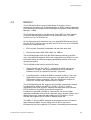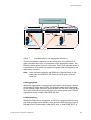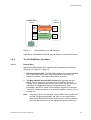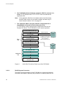
1
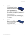
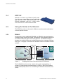
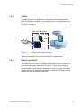
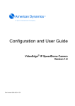
EDN312, ESN108, EXN104, EPN102 User
Guide
EDA 1200
EDN312, ESN108, EXN104, EPN102
User Guide
EDA 1200
.
Copyright
© Copyright Ericsson AB 2006 - 2009. All rights reserved.
Disclaimer
No part of this document may be reproduced in any form without the written
permission of the copyright owner.
The contents of this document are subject to revision without notice due to
continued progress in methodology, design and manufacturing. Ericsson shall
have no liability for any error or damage of any kind resulting from the use of
this document.
Trademark List
LSA - PROFIL®
LSA - PROFIL is a registered trademark of KRONE Inc.
LSA PLUS®
LSA PLUS is a registered trademark of KRONE Inc.
CORBA®
CORBA is a registered trademark of Object Management Group, Inc.
Broadcom®
Broadcom is a registered trademark of Broadcom Corporation
The following information is for FCC compliance of class B devices, valid for EDN312xa - BFB 401 05/D11
R1B:
Changes or modifications not expressly approved by Ericsson for compliance could void the user's authority
to operate the equipment.
NOTE: This equipment has been tested and found to comply with the limits for a Class B digital device,
pursuant to part 15 of the FCC Rules. These limits are designed to provide reasonable protection against
harmful interference in a residential installation. This equipment generates, uses and can radiate radio
frequency energy and, if not installed and used in accordance with the instructions, may cause harmful
interference to radio communications. However, there is no guarantee that interference will not occur in a
particular installation. If this equipment does cause harmful interference to radio or television reception,
which can be determined by turning the equipment off and on, the user is encouraged to try to correct the
interference by one or more of the following measures:
-
ii
Reorient or relocate the receiving antenna.
Increase the separation between the equipment and receiver.
Connect the equipment into an outlet on a circuit different from that to which the receiver is connected.
Consult the dealer or an experienced radio/TV technician for help
4/1553-HSC 901 101/2 Uen B 2009-02-27
.
Contents
1
Introduction
1
1.1
Revision History
1
1.1.1
This Revision (B)
1
1.1.2
Version (A)
1
2
Introduction to the Nodes
2
2.1
EDN312
2
2.2
ESN108
3
2.3
EXN104
3
2.4
EPN102
4
2.5
Using the Nodes in the Network
4
2.5.1
EDN312
4
2.5.2
ESN108
5
2.5.3
EXN104 and EPN102
5
3
Function Description
7
3.1
Common Functions
7
3.1.1
EDN312, ESN108, EXN104 Fan and Temperature Control
7
3.1.2
Upgrading SW in EXN104 and ESN108 Nodes
11
3.2
EDN312
13
3.2.1
Redundancy and Aggregation Options (EDN312x only)
14
3.2.2
IP DSLAM SW Architecture
16
3.2.3
The IP DSLAM Start Procedure
17
3.2.4
Self Recovery
26
3.2.5
Reset On LAN
26
3.2.6
DHCP Lease Time Issues
27
3.2.7
Remote Storage
27
3.3
EXN104
29
3.4
EPN102
29
4/1553-HSC 901 101/2 Uen B 2009-02-27
iii
Contents
4
User Interface
31
4.1
ESN108 Ethernet and PoE Status LEDs
32
4.2
EDN312 Port Status LEDs
33
5
Basic Configuration
34
5.1
ESN108 Basic Parameters
34
5.2
EXN104 Basic Parameters
36
5.2.1
Default Settings
36
5.2.2
T1 Transmission Parameters
36
6
Software Upgrade
38
7
Maintenance
39
7.1
Replacing a Fan
39
7.1.1
Removing the Fan
39
7.1.2
Mounting the new Fan
39
8
Troubleshooting
41
9
EMC Regulation
43
10
Technical Specifications
44
10.1
General Port Use Designation
44
Glossary
iv
45
4/1553-HSC 901 101/2 Uen B 2009-02-27
Introduction
1
Introduction
This document describes the function, usage and specifications of the EDA
EDN312, ESN108, EXN104 and EPN102. It is intended for planning,
installation and maintenance personnel.
The reader should have a basic understanding of the Internet Protocol (IP).
The guide can be read separately, but for a full understanding of the EDA
system the reader is referred to the System Description.
The guide can be printed on a monochrome printer, but the illustrations are
easier to understand if a color printer is used.
1.1
Revision History
The guide is valid for EDA 4.1 R1A and later. Refer to the Release Notes
for valid versions of the nodes and the application software (SW). Other
product versions, with functions not described in this guide, may be
available.
1.1.1
This Revision (B)
The fan replacement procedure has been corrected.
1.1.2
Version (A)
This is the first version of this manual for EDA 4.1, based on the EDA 4.0
document 4/1553-HSC 901 35/4 Uen B.
Other than editorial changes, this document has been revised as follows:
•
References to TFTP multicast have been removed.
•
References to EDN312xs-i have been included.
•
The node technical specifications (previously part of section 10 on
page 44) have been removed, since the node datasheets are included
in the Customer Product Information.
4/1553-HSC 901 101/2 Uen B 2009-02-27
1
Introduction to the Nodes
2
Introduction to the Nodes
EDN312, EXN104, ESN108 and EPN102 are the nodes that make EDA
able to offer very flexible, as well as high volume cost efficient broadband
solutions. These nodes can be combined in different ways and with other
EDA nodes to create a specific solution.
2.1
EDN312
The EDN312 is a small, cost-efficient, 12port IP DSLAM designed for the EDA
solution. It aggregates 12 ADSL lines to
one or two 100 Mbps Ethernet and offers
aggregation both as bridge mode or
routed encapsulation mode.
The IP DSLAM can be used with the EDA subrack solutions and outdoor
cabinet. Management wise it can be managed as a part of an Ethernet
Access Node (EAN) or as a stand-alone node with the PEM management
system.
EDN312 is powered over the Ethernet cable. Power, End-user data and
management traffic run in the same Ethernet cable. EDN312x versions,
which include two Ethernet uplink connections, can be used for power
redundancy, uplink redundancy (RSTP), or link aggregation
EDN312xs versions are cost effective nodes with one Ethernet uplink and
no line LEDs (see section 4.2 on page 33 for more information about line
LEDs).
Subscriber legacy POTS connection to the local exchange is not changed
by the IP DSLAM, which means that telephony service can still be provided
to the subscribers in addition to ADSL.
The IP DSLAM is also fully suitable as a highly scalable standard DSLAM
where each block is a stand-alone node that aggregates 12 ADSL lines into
a standard Ethernet switch instead of a special designed box with back
plane. It is mounted on KRONE PROFILE rod mounting system (KRONE
LSA-PLUS EC 25).
The IP DSLAM is fully managed through SNMP. Most of the management
including line provisioning can also be done locally by using the ECN330
LCT.
2
4/1553-HSC 901 101/2 Uen B 2009-02-27
Introduction to the Nodes
2.2
ESN108
The ESN108 is a small Fast Ethernet
Layer-2 aggregation switch developed for
the EDA solution. It is used for
concentrating the data traffic upwards in
the network.
The ESN108 switch is equipped with 8
electrical 100Mbps Fast Ethernet ports,
and two redundant Small Form-factor
Pluggable (SFP) optical modules with 100/1000 Mbps (Single Mode Fiber,
Dual Fiber) intended to be used for the uplink. It is also possible to use one
of the electrical ports as an uplink.
The switch can supply Power over Ethernet to EDA nodes, which are
connected to the electrical ports.
The ESN108 can be mounted on rods or U-shaped back mount frames.
The switch can be managed through any Ethernet port, using PEM and the
Local Craft Tool (LCT).
2.3
EXN104
The EXN104 is a small managed Fast
Ethernet to E1 or T1 converter
developed for EDA rollout where no
Ethernet uplink is available. Up to four
E1 or T1 lines can be used in parallel.
This is a cost-effective solution for
transporting the Ethernet traffic through vacant E1 lines using the EXN104.
4/1553-HSC 901 101/2 Uen B 2009-02-27
3
Introduction to the Nodes
2.4
EPN102
EPN102 is a Power over Ethernet (PoE) node.
It is built as a crossed Ethernet connection that
can feed two other EDA nodes with PoE.
EPN102 distributes -48V DC to EDA nodes
over free wires in a CAT5 Ethernet cable.
2.5
Using the Nodes in the Network
The EDA Box nodes can be used in different scenarios and combinations
to suit a specific solution.
2.5.1
EDN312
As opposed to many traditional DSLAMs, the EDN312 also terminates the
ATM layer used on top of the ADSL connections, thus interfacing directly to
the switched Ethernet within the Access Domain. The EDN312 bridges
between the switched Ethernet and the Ethernet at the customer premises,
see Figure 1 on page 4, where the IP DSLAM is used in a medium subrack
solution.
Local Loop
CPE
Modem
IP
DSLAMs
Router/
BRAS
Customer Premises
Figure 1
Access Domain
Bridging the Access Domain and the CPE Ethernet
The IP DSLAM can be used as a stand-alone node, aggregated by a
simple PoE switch and controlled directly by PEM, as part of an Ethernet
Access Node (EAN) where it is controlled by the Ethernet Controller Node
(ECN).
4
4/1553-HSC 901 101/2 Uen B 2009-02-27
Introduction to the Nodes
2.5.2
ESN108
The ESN108 can be used whenever aggregation and powering of up to
eight IP DSLAMs is needed. The most typical use is in a small remote site,
where the ESN108 will also supply the IP DSLAMs with PoE as illustrated
in Figure 2 on page 5.
EDA Small site solution
Broadband
Network
-48 VDC
FE/GE
ESN108
Router/
GE BRAS
Ethernet
Switch
EDA Access
Domain
IP DSLAMs
Figure 2
ESN108 Use in an EDA System
Note that the ESN108 can use either electrical or optical uplink.
2.5.3
EXN104 and EPN102
The EXN104 can be used for utilizing unused copper lines to a remote site.
It can be used together with other FE to E1 or T1 converters. However,
better utilization of the four lines can be achieved when the E1 or T1 lines
are terminated by an EXN104 on both sides. Figure 3 on page 6 illustrates
a typical example of the EXN104 together with an EPN102, which supplies
the EXN104 (and the EDN312) with PoE.
4/1553-HSC 901 101/2 Uen B 2009-02-27
5
Introduction to the Nodes
CPE
Local
Loop
Remote Site
Central Office
FE
FE
1-4 x E1 (T1)
120 Ω Copper
EDN312
Figure 3
6
EPN102
FE to E1(T1)
FE to E1(T1)
Use of the EXN104 and EPN102 in the EDA Network
4/1553-HSC 901 101/2 Uen B 2009-02-27
Function Description
3
Function Description
Some of the functions in the different nodes are common for two or three
nodes, while others are specific for a specific node.
3.1
Common Functions
This section describes functions that are common for at least two of the
nodes.
3.1.1
EDN312, ESN108, EXN104 Fan and Temperature Control
The nodes uses temperature control state for controlling the fans, as
condition for sending temperature related traps, and if the state is TooHigh
- deactivating all the ADSL lines (EDN312 only). The EDN312 will turn off
the LEDs when the temperature reaches 85° C.
The ADSL lines are stopped in order to reduce the power consumption and
avoid damage to the IP DSLAM. The high temperature value is probably
caused by fan failure, high environment temperatures, or blocked air
outlets. The lines remain deactivated until the temperature reaches the
Normal state, when they are activated again, and an alarm-ceasing trap is
sent.
The thresholds between the temperature states contain hysteresis, as
depicted in Figure 4 on page 8. Note that under normal operation the
temperature state will change between Low, Normal and High. The fan
control will try to maintain the Normal temperature state.
4/1553-HSC 901 101/2 Uen B 2009-02-27
7
Function Description
Threshold
tempTooHighCeasing
Trap
Temperature
temperatureTooHigh
Trap
High to
TooHigh
Node temperature
Normal
to High
High or
TooHigh
to
Normal
Low to
Normal
Normal
to Low
State:
Low
Normal
Figure 4
Low
Normal
High
Normal
High
TooHigh
Normal
Temperature States of the Nodes
Table 1 on page 8 lists the thresholds for the different nodes:
Table 1
Temperature Thresholds
Threshold
EDN312 (Cº)
ESN108 (Cº)
EXN104 (Cº)
High to TooHigh
95
95
95
Normal to High
75
75
75
High or TooHigh to Normal
73
73
73
Low to Normal
67
67
67
Normal to Low
65
65
65
Note:
The IP DSLAM EDN110 has a threshold value of 105° C for High to
TooHigh.
The temperature is measured in hot spots that can endure very high
temperature. The temperature is measured with one-minute intervals.
8
4/1553-HSC 901 101/2 Uen B 2009-02-27
Function Description
The Control state changes from Low to Normal, if the temperature is
above threshold Low to Normal, which is 67° C for the EDN312.
The Control state changes from Normal to Low, if the temperature is below
threshold Normal to Low, which is 65° C for the EDN312.
The Control state changes from Normal to High, if the temperature is
above threshold Normal to High, which is 75° C for the EDN312.
The Control state changes from High to Normal, if the temperature is
below threshold High to Normal, which is 73° C for the EDN312.
The Control state changes from High to TooHigh, if the temperature is
above threshold High to TooHigh, which is 95° C for the EDN312.
Note:
If the Control state changes to TooHigh the IP DSLAM will send a
Critical Alarm and deactivate all the ADSL lines. The ADSL lines
are stopped in order to reduce the power consumption and avoid
damage to the IP DSLAM. The lines will be activated again, when
the Control state changes from TooHigh to Normal and an alarmceasing trap will be sent.
Fan Performance States
A fan can be in one of the following performance states: Failed, Poor and
Good, see Figure 5 on page 10.
4/1553-HSC 901 101/2 Uen B 2009-02-27
9
Function Description
Good Performance Alarm
Poor Performance Alarm
Failed Alarm
Fan rotation speed
Threshold 4
Threshold 3
Threshold 2
Threshold 1
State:
Figure 5
Good
Poor
Failed
Poor
Good
Poor
Good
Overview of Performance State for the Fans
Table 2 on page 10 lists the thresholds for the different nodes:
Table 2
Temperature Thresholds
Threshold
EDN312 (rpm)
ESN108 (rpm)
EXN104 (rpm)
Threshold 4
11,000
12,000
12,000
Threshold 3
10,000
11,000
11,000
Threshold 2
7,000
10,000
10,000
Threshold 1
6,000
9,000
9,000
A fan changes the state from Good to Poor, if the rotation speed of the fan
in rpm, after 2 minutes of running at full speed level, is below the Threshold
3.
10
4/1553-HSC 901 101/2 Uen B 2009-02-27
Function Description
A fan changes state from Good or Poor to Failed if the rotation speed of
the fan in rpm, after 30 seconds of running at full speed level, is below
Threshold 1.
A fan changes state from Failed to Poor if the rotation speed of the fan in
rpm is above Threshold 2 and from Failed to Good if the Poor if the rotation
speed of the fan in rpm is above Threshold 4.
A fan changes state from Poor to Good if the rotation speed of the fan in
rpm is above Threshold 4.
Note:
3.1.2
If both fans fail the EDN312 will send a Critical Alarm, which is
ceased when at least one of the fans is not in the failed state any
more.
Upgrading SW in EXN104 and ESN108 Nodes
The EXN104 FE-E1 converter and the ESN108 switch both contain two
types of software modules, that is, the boot SW and the application SW.
In the following the SW upgrading process is described in details. The two
nodes are, in practice, upgraded through PEM, or alternatively through the
ECN330 or ECN320 depending on which of the controller nodes that has
been used in the EDA system to control the nodes.
For information on how to use PEM to upgrade the application and boot
software in EDA nodes, both stand-alone and embedded nodes, the
operator should consult the Update Description for Windows Platform or
Update Description for Solaris Platform, and the ECN User Guide. The
Network Configuration Guide, which is one of the PEM guides, also
describes the upgrade procedure in some details.
From a theoretical point of view both software modules, application and
boot software, can be upgraded remotely using SNMP commands. The
boot SW is stored in one single flash area and will be replaced when
upgrading. The application SW is stored in an active and passive flash area
allowing a secure upgrade procedure.
When an application SW upgrade has been ordered through DHCP, the
node downloads the SW module from the Domain File Server, using a
TFTP server, and stores the SW in the passive flash area, see Figure 6 on
page 12. By using a header pointer the role of the two areas are swapped,
which means that the former passive area is changed to become the active
area and the former active area is changed to become the passive area.
Next step is to reboot and the node will now restart with the latest
downloaded version of the application SW.
4/1553-HSC 901 101/2 Uen B 2009-02-27
11
Function Description
If no module is stored in any of the flash areas of the node, a SW module
will be downloaded from the Domain File Server using TFTP.
Priorities between the different possible SW applications are: active flash
area, passive flash area and then module from the Domain File Server.
This means that the switch will start using the application SW in the active
area first, and if the active area does not contain any SW it will try to use
the application SW stored in the passive area. If the passive area does not
contain any SW the node will start downloading the application SW from
the Domain File Server as described above.
Passive Area: New Application SW
TFTP
New Application SW
Flash memory
Active Area: Old Application SW
Domain File Server
The Active Area and the
Passive Area Swaps “Role”
Active Area: New Application SW
Flash memory
Passive Area: Old Application SW
The node is Rebooted and will start-up
with the new application SW
Figure 6
12
Upgrading Application SW to the ESN108 or EXN104
4/1553-HSC 901 101/2 Uen B 2009-02-27
Function Description
3.2
EDN312
The IP DSLAM is able to provide high speed IP access to all the
subscribers simultaneously. Service activation of ADSL is done individually
per subscriber line through the EDA Management System (Public Ethernet
Manager – PEM).
The IP DSLAM has built-in Gas Discharge Tube (GDT) for Over Voltage
Protection and secondary protection on all subscriber lines. The GDT
conforms to ITU-T K.20 and K.21.
On the local loop each subscriber has up to eight ATM Permanent Virtual
Circuits (PVCs), however at most there can be 72 PVCs in one IP DSLAM.
Each can be configured with:
•
ATM cell rate: Peak and Sustainable cell rate, Max burst size
•
ATM service class: UBR, CBR, VBR-rt or VBR-nrt
The IP DSLAM maps traffic from the EDA Ethernet network to the Enduser, using different schemes, which are configurable from PEM. For more
information about the different mapping possibilities, please refer to the
System Description.
The IP DSLAM is also able to perform two tests:
•
Single Ended Line Test (SELT) - estimates the ADSL connection
properties. The SELT can be performed when the IP DSLAM is
installed. No CPE is required for the SELT execution.
•
Loop Diagnostics – defined in ADSL2 standard (G.992.3). The Loop
diagnostics measures the line properties, from both sides (Central
Office and Customer premises). The Loop Diagnostics require an
active CPE modem that supports ADSL2 or higher.
The IP DSLAM HW and SW supports various ADSL transmission modes
including ADSL, ADSL2 and ADSL2+ (G.992.1, G.992.3, G.992.5
respectively) with multi annexes, meaning that both base band services
POTS (Annex A), and ISDN (Annex B) are supported.
Furthermore, the ADSL2 (G.992.3) "symmetrical" service for higher
upstream bandwidths (Annex M) is supported. Also a special version of the
ADSL2 Annex M is supported with underlying POTS service. The IP
DSLAM also supports G.Lite (G992.2) with the same SW.
The ADSL (1, the first ADSL standard) downstream line rate is limited to
approximately 8 Mbit/s, but according to the G.992.1 this can be
increased by use of the optional S=½ feature. Increasing the downstream
4/1553-HSC 901 101/2 Uen B 2009-02-27
13
Function Description
line rate requires the CPE modems to support S=½. The higher line rate is
obtained by configuring the maximum interleave delay greater than 0
(which enables the ATUC S=½). The minimum and maximum bit rates
must be set for the line correspondingly. Tests have shown that a maximum
ADSL line rate of 11-13 Mbps should be attainable.
The ADSL2 transmission modes supports only interleaved path. Therefore
the IP DSLAM cannot directly be configured to fast latency. However, if the
transmission mode is selected to ADSL (1) and interleaved delay is
configured to zero, the IP DSLAM will use the fast path. For a detailed
description of how to configure the line please see the PEM User's Guide.
Furthermore the IP DSLAM supports the ADSL2+ standard, capable of
downstream line rates of up to 24480 kbps (ADSL2+ standard) and
approximately 29 Mbps (when connected to a CPE Modem based on a
Broadcom ADSL2+ chipset).
3.2.1
Redundancy and Aggregation Options (EDN312x only)
The EDN312x versions (EDN312xp, EDN312xi, EDN312xe and
EDN312xa) have two uplink ports, which facilitate power supply
redundancy, and either link aggregation (IEEE 802.1ad) or link redundancy
(by utilizing RSTP-like function). Figure 7 on page 15 illustrates these
possibilities.
14
4/1553-HSC 901 101/2 Uen B 2009-02-27
Function Description
2nd Level Aggregation Switch
RSTP Enabled
RSTP Enabled
Standby
Active
Link Aggregation
Link Redundancy
Data and management
Figure 7
Link Redundancy and Aggregation Scenarios
There is no difference between the two uplink ports of the EDN312x. It
does not matter which port is connected to which aggregation switch. The
EDN312x draws power from one of the links. There is no indication and it is
not possible to know which link supplies the power (this also applies to the
redundancy scenario).
Note:
If the link that is supplying the EDN312x is disconnected, or the
power fails, the EDN312x will restart and draw power from the
other link.
Link Aggregation
When Link Aggregation is deployed for the first time, the link that is first up
will be used for all the uplink traffic. The downlink traffic will be distributed
by the Ethernet Node Controller (ECN) between the two links. After the first
time, the IP DSLAM will always first try the link that was last used. The link
aggregation facility complies with IEEE 802.3ad.
Link Redundancy
When Link Redundancy is deployed, one ECN is configured as active and
one ECN is configured as standby. Only the active ECN will reply to the IP
DSLAM’s DHCP request with a valid DHCP offer. In both ECNs, RSTP is
4/1553-HSC 901 101/2 Uen B 2009-02-27
15
Function Description
enabled. The EDN312x detects the active ECN by the valid DHCP offer,
and uses only that link. If the link becomes inactive, or the uplink from the
active ECM320 is down, the EDN312x will switch over to the other link (on
basis of the RSTP). The EDN312x will keep its IP address as long as the
DHCP lease is valid. If the DHCP lease expires while the connection to the
active ECN is still down, the EDN312x will restart in an unmanaged mode.
As long as the EDN312x is using the standby ECN, remote storage is not
used.
When the active ECN is up again, the EDN312x will switch back to it. If the
EDN312x was in an unmanaged mode, it will restart. If it still has a valid IP
address, the switchover will be without a restart.
Note:
3.2.2
The IP DSLAM may be powered from the standby ECN, while all
the traffic goes through the link to the active ECN.
IP DSLAM SW Architecture
The IP DSLAM uses four main SW elements:
•
Reset SW
•
Boot SW
•
Application SW
•
Configuration File
All four elements are saved in the non-volatile memory (Flash) of the IP
DSLAM. The configuration file is only used for emergency cases when the
DHCP Server or Domain File Server is unavailable.
The application SW and configuration file are installed on the Management
Server. The Domain File Servers stores all the applications, configuration
files and DHCP data of the IP DSLAM (Remote Storage, see section 3.2.7
on page 27, in an Access Domain, see the PEM User Guides for more
information).
16
4/1553-HSC 901 101/2 Uen B 2009-02-27
Function Description
IP
DSLAM
Domain File
Server
FTP
Server
TFTP
Server
Figure 8
Up-/Download
of Remote Storage
files
Download
application and
configuration files
FTP
Client
TFTP
Client
Upload/Download of SW Elements
Note that an embedded IP DSLAM uses its ECN as a Domain File Server.
3.2.3
The IP DSLAM Start Procedure
3.2.3.1
Normal Start
When the IP DSLAM has been installed and is powered up it will do the
following, see Figure 9 on page 18:
1. Execute the Reset SW. The Reset SW unpacks the compressed Boot
SW. If more than one version of Boot SW exists in the Flash, the
newest is selected. The selected Boot SW is executed.
2. The Boot SW will issue a DHCP request and negotiate with the
DHCP Server, from which it will receive an IP address for the IP
DSLAM, the IP address of the Domain File Server and the names of
and path to the application SW and configuration files. Other
information, like DHCP option 82 for example, may also be received.
The DHCP request procedure is described in details in section 3.2.3.2
on page 18.
Note:
If the active ECN is unreachable, and the DHCP offer comes from
an ECN configured as standby, the offer is in an invalid format.
When the IP DSLAM detects the invalid format, it will immediately
start from the Flash (used in link redundancy during switchover).
4/1553-HSC 901 101/2 Uen B 2009-02-27
17
Function Description
3. The IP DSLAM will download the application SW file and store it in
Flash. The IP DSLAM uses a TFTP or FTP client to download the
application SW.
Note:
4.
If the application SW file to be loaded matches the file already
stored in flash, the file is not loaded. Instead, the flash copy is
used. See also section 3.2.3.4 on page 20.
The application SW is executed, and the configuration file is
downloaded and stored in Flash ready to be used.
A TFTP client is used to download the configuration file from the
Domain File Server. The IP DSLAM is now in normal operation.
IP DSLAM Starts (Power up)
DHCP request
Run Boot SW
DHCP response:
Boot
SW
New IP Address used
by the IP DSLAM
DHCP
Server
IP address of IP DSLAM
and Domain File Server
name and path to
Appl. SW and Conf. File
Download Application SW
Domain
File
Server
Store Application SW to Flash
Run Application SW
Application
SW
Download Configuration File
Store Configuration File to Flash
IP DSLAM runs in normal
managed mode
Figure 9
3.2.3.2
Initial Start Procedure (Power up) of the IP DSLAM
DHCP Request Procedure
The DHCP request procedure of the IP DSLAM is a compromise between
robustness and speed. Optimizing the procedure for startup speed will not
18
4/1553-HSC 901 101/2 Uen B 2009-02-27
Function Description
ensure that the IP DSLAM will always be able to start. Optimizing for
robustness will result in longer startup time. Both the Boot SW and the
Application SW can run the DHCP procedure. Under normal network
conditions, it will always be the Boot SW that runs the DHCP procedure
during startup. The Application SW will only run the procedure if there is no
reply for over four minutes during startup, or after the IP DSLAM is running
with the application SW (when the DHCP lease expires). Figure 10 on page
19 illustrates the DHCP procedure. Note that the procedure also
accommodates Dynamic Management VLAN (DMV) that also uses
untagged traffic. For more information about how the DMV works, please
refer to Dynamic Management VLAN Configuration Guide.
Retrieve Management VLAN ID
from flash
Send tagged DHCP request
Timeout
2 min.
No
Normal Start-up
DHCP Response
received?
Yes
Send untagged DHCP request
Yes
DHCP Response
received?
No
Timeout
2 min.
No
DHCP Response
Valid?
Yes
Change Management VLAN ID
Use IP Address from DHCP
IP DSLAM runs Unmanaged
Figure 10
IP DSLAM Runs Managed
DHCP Procedure
In normal network conditions (all network resources are available) the IP
DSLAM will immediately receive a legal DHCP response. After validating
the legality (format) of the response the IP DSLAM will use the received
parameters and proceed with the startup procedure. The procedure always
4/1553-HSC 901 101/2 Uen B 2009-02-27
19
Function Description
ends with either managed or unmanaged mode. In both modes End user
traffic will continue to flow. In the managed mode the IP DSLAM has an
IP addressed and can be managed from PEM (or through the ECN CLI). In
Unmanaged mode, the IP DSLAM does not have an IP address, and its
configuration cannot be changed. It uses the configuration stored in the
flash memory. When running in unmanaged mode the IP DSLAM cannot
use remote storage.
The running mode (Managed or Unmanaged) of the IP DSLAM is kept in a
section of the RAM that is not cleared at restart. This way the mode setting
survives a restart and can be tested by the BOOT loader. If the RAM has
lost its contents, for example after a sufficiently long power-off
(approximately 30 seconds), then the mode is set to Managed.
3.2.3.3
Application Software Download
The Boot SW is able to use either FTP or TFTP to download the
Application SW and configuration files (configuration file can only be
downloaded by TFTP). The protocol used for the Application SW download
is determined by the extension of the file. TFTP will be used if the extension
of the file is either “.tft” or “.tftp”. FTP will be used for any other extension.
3.2.3.4
Restarting the IP DSLAM
When an IP DSLAM is restarted the procedure is almost the same as when
it is initially powered up with the exception that the Application SW in Flash
will be compared to the Application SW on the Domain File Server.
If the files are identical the Application SW will be run from Flash. If the file
names are different the IP DSLAM will download the SW from the Domain
File Server. This procedure is illustrated in Figure 11 on page 21.
20
4/1553-HSC 901 101/2 Uen B 2009-02-27
Function Description
IP DSLAM Restart
Run Boot SW
Yes
Was the last mode
unmanaged?
No
DHCP
Server
DHCP procedure
IP Address used
Yes
Is the Appl. SW file
identical to Flash?
No
Download Appl. SW
And store in flash
Domain File
Server
Run application SW in
managed mode
Run Application SW from Flash
in unmanaged mode
Figure 11
Download and store
Configuration file to Flash
Restarting the IP DSLAM (Normal Procedure)
The stored mode – Managed or Unmanaged – is used to determine
whether the IP DSLAM should try to reach the DHCP server or not. If the
last mode was unmanaged, the IP DSLAM will start from the flash
immediately, skipping the DHCP procedure and saving start-up time. The
application will then go on polling for the DHCP server, but End user traffic
would flow in the meantime.
3.2.3.5
Start with Missing Servers
In the following the IP DSLAM behavior is described when one or more
network elements cannot be reached. The descriptions are based on a
distributed network where the DHCP Server and Domain File Server are
not installed on the same machine, but the IP DSLAM behavior will be the
same if the DHCP Server and the Domain File Server are installed on the
same machine. Note that the IP DSLAM continuously saves changes that
are made (both in Application SW and configuration) to Flash. This means
that both the Application SW and the configuration loaded from Flash will
be the last ones used.
4/1553-HSC 901 101/2 Uen B 2009-02-27
21
Function Description
3.2.3.6
Start without a DHCP Server (Start from Flash)
The following description does not take the unmanaged last mode into
account (for simplicity reasons). The only difference is where the DHCP
procedure is run from. If the last mode was unmanaged, the DHCP
procedure will be run from the application SW. If the last mode was
managed, the DHCP procedure will be run from the boot SW.
There are two scenarios that concern the DHCP server:
1. The DHCP server does not respond at all
2. The DHCP server responds with an illegal response (from a standby
ECN)
Figure 12 on page 22 illustrates the start-up of an IP DSLAM when there is
no DHCP response at all. Note the two timeouts of 2 minutes each: one
waiting for response in the tagged management VLAN, and the other
waiting for response in untagged traffic.
Start-up with
no DHCP Server
Retrieve Management VLAN ID
from flash
Send tagged DHCP request
Timeout
2 min.
DHCP Response
No
received?
Yes
Send untagged DHCP request
Yes
DHCP Response
No
received?
Timeout
2 min.
No
DHCP Response
Valid?
Yes
Change Management VLAN ID
Use IP Address from DHCP
IP DSLAM runs Unmanaged
Figure 12
22
IP DSLAM Runs Managed
IP DSLAM Start-up Without DHCP
4/1553-HSC 901 101/2 Uen B 2009-02-27
Function Description
Figure 13 on page 23 illustrates the start-up of an IP DSLAM when the
response comes from a standby ECN. The response is not a legal
response and the IP DSLAM skips the timeouts thus reducing the startup
time to approximately 30 seconds.
Retrieve Management VLAN ID
from flash
Send tagged DHCP request
Timeout
2 min.
DHCP Response
No
received?
Start-up with
illegal DHCP
response
Yes
Send untagged DHCP request
Yes
DHCP Response
No
received?
Timeout
2 min.
No
DHCP Response
Valid?
Yes
Change Management VLAN ID
Use IP Address from DHCP
IP DSLAM runs Unmanaged
Figure 13
IP DSLAM Runs Managed
IP DSLAM Start-up Without DHCP from a Standby ECN
While running in unmanaged mode, the IP DSLAM will keep on polling the
DHCP server approximately one minute after a previous polling is ended.
If the DHCP lease expires and the IP DSLAM cannot renew the license, it
will change the last mode state to unmanaged and restart.
4/1553-HSC 901 101/2 Uen B 2009-02-27
23
Function Description
3.2.3.7
Start without a Domain File Server
Upon reboot the IP DSLAM sends a DHCP request. It receives data (IP
address of Domain File Server, name and path to Application SW and
configuration file, IP address of IP DSLAM) from the DHCP Server.
The IP DSLAM will compare the Application SW file name with the name of
the file stored in Flash. If they are identical, the Application SW will be run
from Flash. If the Application SW file names are different, the IP DSLAM
will try to download the SW from the Domain File Server.
The IP DSLAM will try to download the SW for a specific amount of time
and uses an adaptive TFTP timeout. It measures the roundtrip delay (the
time that it takes a packet to reach the destination and back) and sets the
TFTP timeout as 10*roundtrip delay, but always selects a value between
0.5 to 20 seconds. After three timeouts, the IP DSLAM loads and runs the
Application SW from Flash.
From that point on it will try to reach the Domain File Server every minute.
An alarm will be sent only once and when the connection to the Domain
File Server has been re-established and the IP DSLAM is able to download
the configuration file a ceasing alarm is sent.
Any end-user configured in the configuration file and saved in the flash
memory will be able to use the ADSL connection. When the Domain File
Server can be reached again, the IP DSLAM will download the
configuration file and compare it with the file saved in the Flash. If they are
identical, the downloaded file will be discarded, and the IP DSLAM will be in
normal operation state. If the configuration file is different, the IP DSLAM
will reboot and go through a normal reboot procedure.
24
Note:
Subscriber traffic will be interrupted during reboot. Figure 14 on
page 25 illustrates the start scenario when the Domain File Server
cannot be reached by the IP DSLAM.
Note:
Only the configuration file is compared. If the Application SW has
been changed, PEM will always check that the IP DSLAM is
running with the SW specified in PEM.
4/1553-HSC 901 101/2 Uen B 2009-02-27
Function Description
IP DSLAM Reboot
DHCP request
Run Boot SW
IP Address etcetera
DHCP
Server
New IP Address used
Yes
Check if the Appl.
SW file name is identical to
Flash
Run Application SW
from Flash
Download
Configuration File
No
Download Appl. SW
Timeout
Run Appl. SW from
Flash
Timeout
Try to download Configuration
Use Configuration File from Flash
Alarm (every 10th minute)
Domain File Server Up again
Domain
File
Server
Download Configuration File
Yes
Check if
Downloaded Configuration
is identical to Flash
configuration
Continue in normal mode
Figure 14
4/1553-HSC 901 101/2 Uen B 2009-02-27
No
IP DSLAM Reboot
IP DSLAM Start with no Domain File Server Reachable
25
Function Description
3.2.4
Self Recovery
The IP DSLAM contains a self-recovery timer (keep alive counter), which
will reboot the IP DSLAM if there has been no traffic (that is management
polling, subscriber traffic or broadcast beacons from other nodes) for six
hours (default).
In order to ensure that there is always some traffic in the network, the
EDN312 and EXN104 sends a broadcast beacon every 30 seconds.
The time from the traffic stops and the IP DSLAM reboots, will be between
6 and 12 hours, depending on how far the counting got when the traffic
stopped, as illustrated in Figure 15 on page 26.
Note:
The IP DSLAM broadcast beacon can be stopped if desired, using
the Advance Node Configuration facility in PEM. This is however
not recommended, since it may result in IP DSLAM restart in
periods with no traffic.
Traffic
No traffic
Broadcast beacons
from other EDA nodes
No traffic at all
Keep-alive timer
6 hours
Reboot
Figure 15
6 hours
6 hours
Reboot
Self-Recovery Mechanism
The keep alive counter time can be changed from PEM by changing the
value of the timer in the engineeringServer.properties file. For
more details about how to change values in .properties files, please refer to
the PEM Advanced Configuration Guide.
3.2.5
Reset On LAN
The IP DSLAM can be rebooted from PEM if necessary by using the Reset
On LAN facility. The Reset On LAN is a special Ethernet frame (Wake-onLAN like) that can be used even if the IP DSLAM is running without an IP
26
4/1553-HSC 901 101/2 Uen B 2009-02-27
Function Description
address. Note that the Reset-on-LAN frame has a proprietary format and
that a standard Wake-on-LAN frame will not restart the IP DSLAM.
3.2.6
DHCP Lease Time Issues
If the DHCP Server is down for a long time, the lease time of the IP
DSLAM’s IP address might expire, without the IP DSLAM being able to
renew it. In such a case, the IP DSLAM will reboot, and start with the same
scenario described in previously, that is start from Flash without an IP
address after four minutes timeout, and then keep on searching afterwards
for a DHCP Server.
Therefore it is recommended to configure the lease time of the DHCP
Server to long periods. The IP DSLAM will start to renew the lease time
after half of the lease time has passed. For example, if the lease time is set
for eight days, then the DHCP Server will have to be down for a period of
four days before the IP DSLAM will reboot.
3.2.7
Remote Storage
If an IP DSLAM reboots while the customer equipment (for example a PC)
is connected, the customer will not be able to continue the session without
requesting a new IP address (rebooting the PC or releasing the old IP
address). To address this problem, remote storage is used.
The remote storage is used for saving data that cannot be stored in Flash
and should survive a reboot.
The remote storage is used for saving the IP addresses of the Customer
Premises Equipment (CPE) and if PPPoE is used as the access method,
the MAC address of the CPE as well.
The IP DSLAM filter blocks any traffic to an IP address or MAC address it
does not know. The known IP addresses are obtained either from PEM
(static IP address) or from the DHCP traffic. After a reboot, the list will be
empty, but since the CPE already has an IP address, the CPE will not
make a new DHCP request. All traffic to and from the End-user will
therefore be blocked, until the lease time expires, or by releasing the old IP
address in the CPE, which will result in a new DHCP request issued by the
CPE. If PPPoE is used, the MAC address of the CPE is restored after a
reboot, in order to continue the PPPoE session.
The IP DSLAM uses the Domain File Server as remote storage media and
utilizes an FTP session to upload and download data from the Domain File
server, see Figure 8 on page 17.
4/1553-HSC 901 101/2 Uen B 2009-02-27
27
Function Description
Each time a change occurs in the dynamic IP address table in the IP
DSLAM (that is, each time a user receives or releases an IP address), the
IP address table is saved to the Domain File Server. Each time the IP
DSLAM restarts, it will download the IP address table from the Domain File
Server.
For each entry (IP address), the IP DSLAM also saves the line (from which
it came), the real time, the lease time and the MAC address. When the
entry is retrieved, the IP DSLAM checks that the IP address is still valid
(with respect to the current time, the time the address was given and the
lease time). If the IP address is not valid, it will be discarded.
The remote storage is also used for storing traffic counters, that is, the
frame counter for downstream traffic and the frame counter for upstream
traffic. The counter will normally be reset when an IP DSLAM restarts.
When the counters are stored in the remote storage, the counters can
upload with the values before the restart.
To survive situations where the domain server is not available after a
reboot, the IP DSLAM keeps a copy of the saved remote storage data in
RAM. This RAM is not erased at reboot. When the IP DSLAM restarts, it
will check the validity of the RAM storage area first and use this copy
without fetching any data from the remote storage file. The remote storage
file can therefore be seen as the non-volatile backup of the remote storage
data, which is kept locally in RAM in the IP DSLAM itself.
3.2.7.1
Time Synchronization
In order to be able to time stamp entries in the Remote Storage, and
evaluate them when they are retrieved, the IP DSLAM has a real time
synchronization. A Simple Network Timing Protocol (SNTP) agent is
implemented in the IP DSLAM. The IP DSLAM synchronizes upon reboot,
and then every 12 hours.
The IP DSLAM can synchronize with any SNTP server, either in the Access
Domain, or with a central server. Figure 16 on page 29 illustrates both
scenarios. In the Access Domain1, there is a Time Synchronization Server
in the Domain, and the IP DSLAMs synchronize with it. The server is
synchronized with the Access Providers Main Time Server or any other
Time Server. Access Domain2 does not have a Time Synchronization
Server and the IP DSLAMs must therefore synchronize directly with the
main external Time Server.
28
4/1553-HSC 901 101/2 Uen B 2009-02-27
Function Description
Access Provider Main
Time
Synchronization
Server
Time
Synchronization
Server
Access
IP
Domain1
IP
DSLAM
DSLAM
Figure 16
3.3
Access
IP
Domain2
IP
DSLAM
DSLAM
Time Synchronization Scenarios
EXN104
The EXN104 has a single RJ-45 port, which supports 100BASE-TX on CAT
5 cables and conforms to IEEE 802.3u. On the MDF interface the EXN104
supports four 120Ω E1 ports (2048 kbps), which conforms to ITU-T G.703.
The ports can also be connected to T1 lines, but this will require changing
the basic configuration as explained in section 5.2.2 on page 36.
The EXN104 is powered through the Ethernet port (PoE, similar to the
IP DSLAM). It is fully manageable using SNMP from PEM. The EXN104
can operate autonomously because firmware and configuration are stored
in flash.
All software and firmware can be upgraded through the FE and E1 ports
(thus enabling upgrade of nodes placed at both the central and the remote
site). Software and firmware upgrades are done from PEM.
3.4
EPN102
The EPN102 is capable of distributing power (-48 V DC) to two EDA nodes.
It is intended to be used as a power distribution unit for one IP DSLAM and
one EXN104 (Ethernet to E1 converter) in a remote site. The EPN102 is
mounted in a 10-line KRONE LSA block. Fast Ethernet is accessed through
two shielded RJ45 connectors that are crossed connected internally in the
EPN124. The EPN102 is grounded through the LSA block. The EPN102 is
unmanaged.
The EPN102 provides the following external interfaces:
4/1553-HSC 901 101/2 Uen B 2009-02-27
29
Function Description
30
•
One Fast Ethernet (FE), 100BASE-TX according to ANSI/IEEE STD
802.3, clause 25. The LAN connection is implemented as crossed
cable.
•
Two Power over LAN outputs, connected according to IEEE DRAFT
P802.3AF/D3.1, clause 33, alternative B
•
One -48V input port.
4/1553-HSC 901 101/2 Uen B 2009-02-27
User Interface
4
User Interface
All the nodes’ main user display have two colored LEDs in the front. The
EDN312 and ESN108 have additional port LEDs (one for each port), which
indicate the state of the port. The port status LEDs are disabled by default,
in order to save power. These LEDs can be activated from PEM.
Table 3
Main LED Indications
LEDs Indication
Node Status
Green
Red
••••••
••••••
Power-on: Initial LED state
During operation: major HW error
Green
Red
••••••
Power-on: Boot SW starting (2.5 flashes per second)
Green
Red
••••••
••••••
••••••
Power-on: Loading application SW
(approximately 8 flashes per second)
Green
Red
••••••
••••••
Power-on: Switching from Boot SW to application SW (…or
not powered on)
Green
Red
••••••
Normal operation
Green
Red
••••••
••••••
••••••
Information: No DHCP offer received or SW upgrade in
progress (2 flashes per second)
Green
Red
••••••
Minor error, or service needed
Green
Red
••••••
Green
Red
••••••
••••••
••••••
••••••
Legend: █ or █ : LED is On
4/1553-HSC 901 101/2 Uen B 2009-02-27
Indication set manually from the PEM, to point out a
specific node (for example to help maintenance personnel
to locate a node in the MDF). Light shift every second.
EXN104 only: All E1 links are down (Short flash every 1.5
seconds)
• : LED is Off
31
User Interface
4.1
ESN108 Ethernet and PoE Status LEDs
Port 1-8 are electrical Ethernet ports, which can be configured for delivering
Power over Ethernet, and the 8 LEDs can therefore indicate the link status
(status green) and fault in the Power over Ethernet operation (status red).
The LED for port 9 indicates the link status of the optical Ethernet port, if
equipped with a Small Form-factor Pluggable (SFP) module. Note that port
9 is indicated, in the display, as A (Aggregate).
Table 4
Ethernet and PoE LED Indication on the ESN108 Switch
Status LED
ESN108 Ethernet Status
•••••••
Power over Ethernet failure (only port 1-8)
(flashes approximately 6 time per second)
•••••••
Link is not established or no SFP plugged in port 9
•••••••
Link is established
•••••••
Link is established.
Data is transmitted or received at 10 Mbit/s Ethernet
(flashes approximately 3 times per second)
•••••••
Link is established.
Data is transmitted or received at 100 Mbit/s Ethernet
(flashes approximately 6 times per second)
Legend: █ or █ : LED is On
• : LED is Off
32
4/1553-HSC 901 101/2 Uen B 2009-02-27
User Interface
4.2
EDN312 Port Status LEDs
The Line status indicators are LEDs shown as numbers on the EDN312.
Each number LED shows the status of the corresponding line. The function
of the Line Status indicators is normally turned off to save power. They can
be activated for approximately 30 (±10) minutes from PEM (IP DSLAM
Properties in the Network Configuration Manager), when needed, after
which, PEM will turn off the Line Status LEDs again. The Line LEDs
indicates the following:
Table 5
EDN312 Line LEDs
Line LED
Condition
Status
•••••••
Line not activated
•••••••
The IP DSLAM is training or trying to train the line
•••••••
The line is active (OK)
Legend: █ : LED is On
• : LED is Off
Note:
The Line Status LEDs are invisible when they are off.
Note:
The Line Status LEDs do not exist in EDN312xsp, EDN312xs-p,
EDN312xse and EDN312xs-i.
4/1553-HSC 901 101/2 Uen B 2009-02-27
33
Basic Configuration
5
Basic Configuration
Since the nodes get the entire network configuration from the DHCP
Server, the nodes need no configuration. The Management VLAN ID is
stored in flash memory (VLAN ID 246) when dispatched from the factory.
When the nodes are embedded nodes in an EAN, the management VLAN
is configured automatically by the ECN (default VLAN ID 247).
If the node is not an embedded node, the Management VLAN ID can be
changed from the Local Craft Tool (LCT), or by using the Dynamic
Management VLAN concept (please refer to Management VLAN
Configuration Guide or Local Craft Tool User Guide for detailed
information).
Apart from the Management VLAN ID, the EDN312 receives its entire
configuration from a Configuration File located on the Domain File Server.
The ESN108 and EXN104 have their default configuration stored in the
flash memory when dispatched from the factory.
5.1
ESN108 Basic Parameters
Under normal conditions, the ESN108 is managed through PEM. However,
for some tasks the Local Craft Tool is used.
The ESN108 has a set of default data stored in Flash-memory, which can
be changed through the PEM. The factory default settings are:
•
Power over Ethernet is enabled on Port 1-7.
•
Spanning Tree is disabled.
Note:
Spanning tree is enabled through PEM or CLI to an ECN. The
spanning tree default parameter values correspond to the RSTP
standard. The default values can be changed though CLI to the
ECN (embedded) or Node Advanced Configuration (stand-alone).
The spanning tree parameters are stored in the Flash. Once the
spanning tree is set to enable, it will start with spanning tree
enabled again.
The ESN108 has a set of default data stored in Flash that cannot be
changed from PEM. These are the defaults:
•
34
Management VLAN ID (1 to 4095), default = 246.
4/1553-HSC 901 101/2 Uen B 2009-02-27
Basic Configuration
•
Quality of Service is enabled. Priority barrier is set to 5, which means
that all traffic with a priority equal or higher then 5 will be put in the high
priority queue.
•
IGMP snooping is enabled.
•
Bandwidth Threshold is set to 99%, which means that if the bandwidth
on any port is higher than 99% of maximum supported bandwidth an
alarm will be issued.
•
Flow control is disabled on all ports.
•
Duplex mode is Auto negotiation.
•
Port based VLAN is set to enable traffic flow from uplink to any
downlink port and from downlink ports only to uplink port. This implies
that it is not possible to communicate between the downlink ports by
default. Port 9 (the optical port) and port 8 are configured as possible
uplink ports. Table 6 on page 35 illustrates the factory default settings.
“1” denotes true (the ports may communicate directly) and “2” denotes
false.
Table 6
Traffic Forwarding Table
Ingress
1
2
3
4
5
6
7
8
9
(FE1) (FE2) (FE3) (FE4) (FE5) (FE6) (FE7) (FE8) (Optical)
Egress
1
2
2
2
2
2
2
2
1
1
(FE1)
2
2
2
2
2
2
2
2
1
1
(FE2)
3
2
2
2
2
2
2
2
1
1
(FE3)
4
2
2
2
2
2
2
2
1
1
(FE4)
5
2
2
2
2
2
2
2
1
1
(FE5)
6
2
2
2
2
2
2
2
1
1
(FE6)
7
2
2
2
2
2
2
2
1
1
(FE7)
8
1
1
1
1
1
1
1
2
1
(FE8)
9
1
1
1
1
1
1
1
1
2
(Optical)
4/1553-HSC 901 101/2 Uen B 2009-02-27
35
Basic Configuration
Note:
The traffic forwarding values can be changed by using the Local
Craft Tool. Please refer to the Local Craft Tool User’s Guide for
detailed information.
5.2
EXN104 Basic Parameters
5.2.1
Default Settings
Under normal conditions, the FE-E1 Converter is managed from PEM.
The FE-E1 converter has the following set of default data stored in FLASH
that can only be changed using the Local Craft Tool:
•
E1 line coding, default = HDB3.
•
E1 lines in use (1 to 4), default = 4.
•
E1 framing type (BFA or CRC4), default = CRC4.
•
Synchronization (Clock master or slave), default = clock master.
•
Management VLAN ID (1 to 4095), default = 246.
These default values are commonly used for E1 transmission, and should
bring the E1 link into service in most networks. The FE-E1 converter
(EXN104) automatically selects the synchronization mode, which means
that the converter at the Central Office will run as master and the converter
at the Remote site will runs as slave. If the converter does not know if it is
placed at the Central Office or the Remote site, it will run as master.
The converter can be forced to run as master or slave through PEM.
When the converter is in service it can be configured through PEM but E1
lines in use can only be changed by using the Local Craft Tool. Please refer
to the Local Craft Tool User’s Guide for detailed information about how to
use it.
5.2.2
T1 Transmission Parameters
The EXN104’s default setup is to run in E1 mode, which means that in
order to make it run in T1 mode it must be configured before connecting it
to the network. The SNMP MIB parameters are changed by using the Local
Craft Tool (LCT) and for a detailed description of how to use the LCT
please see the Local Craft Tool User’s Guide. Furthermore, the remote site
must be configured first and then the site at the Central Office.
36
4/1553-HSC 901 101/2 Uen B 2009-02-27
Basic Configuration
In order to enable the EXN104 converter to convert the Fast Ethernet traffic
to T1 lines the SNMP MIB parameters for the EXN104 must be changed as
follows:
1. T1 framing type (D4 or ESF) = ESF
The framing type ESF contains CRC check and is considered the
better of the two formats. Only the line coding B8ZS has been
implemented when running T1. The T1 frame type can be changed “on
the fly”, which means that it is possible to change from EFS to D4 or
vice versa “on-the-fly”. The framing type is set by changing the
dsx1LineType (OID 1.3.6.1.2.1.10.18.6.1.5) in the MIB to either D4 or
ESF. Only one line has to be set, as all the other lines automatically will
change to the new setting.
The framing type is set to ESF by changing the dsx1LineType (OID
1.3.6.1.2.1.10.18.6.1.5) to 2.
The framing type is set to D4 by changing the dsx1LineType (OID
1.3.6.1.2.1.10.18.6.1.5) to 3.
2. Save the new line type by changing the saveCfgToNvm (OID
1.3.6.1.4.1.193.72.600.1.1.12) to 1. This will save the new setting in the
non-volatile memory. Restart the EXN104 to activate the new line type.
The line coding, when running T1, will automatically change to B8ZS,
which is the only coding that has been implemented.
3. The line coding can be verified by reading out the value of the MIB
parameter: dsx1LineCoding (OID 1.3.6.1.2.1.10.18.6.1.6).
4/1553-HSC 901 101/2 Uen B 2009-02-27
37
Software Upgrade
6
Software Upgrade
The application SW of the nodes is upgraded from PEM. Refer to the
Network Configuration Guide for instructions of how to perform a SW
installation and upgrade for an embedded node, that is, a node managed
by an Ethernet Controller Node (ECN).
The boot SW of the nodes can also be updated. Refer to PEM Advanced
Configuration Guide for instructions about how to upgrade boot SW in
stand-alone nodes.
Refer to the ECN User Guide for instructions about upgrading boot SW in
embedded nodes.
When the SW of the EXN104 is upgraded (through PEM), it is a good
practice to always upgrade the Remote Site node first and then the Central
Site node. For details about how to upgrade refer to Network Configuration
Guide.
38
4/1553-HSC 901 101/2 Uen B 2009-02-27
Maintenance
7
Maintenance
The only parts that should be replaced from time to time in the EDN312,
ESN108 and EXN104 are the fans. There is no maintenance work for the
EPN102.
Each node has two fans. The speed of the fans is regulated according to
the temperature. An alarm is issued if a fan stops.
The node will check both fans every 24 hour to validate the quality of the
fan, based on revolutions per minute (rpm) at full speed. An alarm is issued
if a fan fails to reach a specific threshold value.
7.1
Replacing a Fan
Required Tools: Plastic tweezers
Stop!
Use only plastic tweezers to avoid short circuiting the power.
7.1.1
Removing the Fan
The replacement of a fan is done from the front, (see Figure 17 - example
from EXN104). Use the wires (with the tweezers) to pull out the plug. Use
the wires to pull the fan out. In the EDN312 use the tweezers to level the
fan on the opposite side of the wires while pulling it out.
7.1.2
Mounting the new Fan
Stop!
Do not press the rotor directly as this may damage the fan.
4/1553-HSC 901 101/2 Uen B 2009-02-27
39
Maintenance
ESN108 and EXN104:
Insert the keyed plug of the new fan into the socket using the tweezers.
Click the new fan into place (air flow direction must be towards the MDF
connector).
EDN312:
Click the new fan into place (air flow direction must be towards the MDF
connector). Insert the keyed plug of the new fan into the socket using the
tweezers.
2
Figure 17
40
1
Replacing a Fan
4/1553-HSC 901 101/2 Uen B 2009-02-27
Troubleshooting
8
Troubleshooting
Table 7 on page 41 lists faulty situation indications on the main LEDs. For
each fault indication the probable cause and remedy are given. This
information applies to all nodes except EPN102.
Table 7
Troubleshooting
Symptom Indication
Possible Cause
Remedy
Green
Red
••••••
The “Flash LEDs” function in PEM
was activated.
Deactivate the “Flash LEDs” function.
••••••
Green
Red
••••••
One or both fans have stopped.
Replace the faulty fan.
Green
Red
••••••
1.
Temperature too high:
Replace the faulty fan.
One or both fans may be
faulty.
The ambient temperature is
too high.
Make sure that the ambient temperature is
within the specified range.
The HW is faulty or the Flash
contains no valid Reset SW.
Replace the node.
••••••
••••••
2.
Green
Red
••••••
Green
Red
••••••
Green
Red
Check the power node connected to the
node. Check the Ethernet cable through
which the power is supplied.
The IP DSLAM contains no valid
Boot Loader, only Reset SW.
Replace the node.
Boot Command Mode. This mode is
only entered, if the Boot Loader
cannot initiate a DHCP request.
Typically, because there is no valid
Ethernet MAC address stored in the
Flash.
Replace the node.
DHCP Server not reachable and no
SW image stored in the Flash.
Check that the DHCP Server is up, and
verify the connections.
••••••
••••••
••••••
••••••
0.5 s On,
0.5 s Off
(slow blink)
Green
Red
There is no DC power.
••••••
••••••
0.2 s On,
0.2 s Off
(medium blink,
for a period
longer than four
minutes)
4/1553-HSC 901 101/2 Uen B 2009-02-27
41
Troubleshooting
Table 8 on page 42 lists faulty situation indications on the main LEDs
during installation (stand alone nodes) of EXN104. For each fault indication
the probable cause and remedy are given.
Table 8
Troubleshooting of EXN104 during Installation and Registration
Symptoms
Possible Cause
Remedy
Remote node cannot
be registered
Defect E1 links or
incompatible SW
Check the E1 links.
The converter does not
function
Installation of the converter
with the wrong framing type
Change the framing type to the
correct one.
42
4/1553-HSC 901 101/2 Uen B 2009-02-27
EMC Regulation
9
EMC Regulation
The EPN102 conforms to the EN 300 386 (2001-09) standard, whether
shielded or unshielded category 5 LAN cables are used.
Warning!
EPN102 is a Class A products. In a domestic environment, this product
may cause radio interference, in which case the user may be required to
take adequate measures.
4/1553-HSC 901 101/2 Uen B 2009-02-27
43
Technical Specifications
10
Technical Specifications
10.1
General Port Use Designation
The ports of the EDN312, ESN108, EXN104 and EPN102 have the
following port use designation (according to EN 300 386 V1.3.2 [2003-05],
class B):
44
•
Electrical Ethernet ports – Indoor Signal Line Port
•
Optical Ethernet ports – Outdoor Signal Line Port
•
Line ports (EDN312) – Outdoor Signal Line Port
•
Exchange ports (EDN312, excl. EDN312i) – Outdoor Signal Line Port
•
Exchange ports (EDN312i) – Indoor Signal Line Port
•
E1/T1 Lines ports (EXN104) – Outdoor Signal Line Port
4/1553-HSC 901 101/2 Uen B 2009-02-27
Glossary
Glossary
Access Domain
A logical network handled by the OAM
system and defined by the approved IPaddresses. One or more Access Domains
make up an EDA network, which is a
switched Ethernet. An Access Domain is
managed by one Domain Server.
Access Provider
The provider of the physical network enabling
subscriber connection to service providers
and their equipment. In the PEM the Access
Provider deals with Service Providers, and
does not deal with subscribers.
ADSL
Asymmetric Digital Subscriber Line
ATM
Asynchronous Transfer Mode. A network
technology that enables the transmission of
data, voice, audio, video, and frame relay
traffic in real time.
Broadcast Beacon
A repetitive broadcast message sent by a
node at specific time intervals.
Broadcast
Sending a message to all devices connected
to an Ethernet.
CBR
Constant Bit Rate
CRC
Cyclic Redundancy Check
DHCP
Dynamic Host Configuration Protocol
DHCP server
A configuration server, capable of configuring
hosts with a variety of information required for
their operation.
Domain Server
A Domain Server is a server computer that
handles part of the network managed by
PEM.
DSL
Digital Subscriber Line
FTP
File Transfer Protocol
HW
Hardware
IGMP
Internet Group Management Protocol. Used
to establish host memberships in particular
multicast groups on a single network. The
mechanisms of the protocol allow a host to
inform its local router that it wants to receive
messages addressed to a specific multicast
group.
CLI
Command Line Interface
IP DSLAM
IP based Digital Subscriber Line Access
Multiplexer
CORBA
Common Object Request Broker Architecture
IP
Internet Protocol
CPE
Customer Premises Equipment
ISDN
Integrated Services Digital Network
4/1553-HSC 901 101/2 Uen B 2009-02-27
45
Glossary
LAN
Local Area Network
SELT
Single Ended Line Test
LCT
Local Craft Tool
Server
The Server term in the PEM can be either a
robust computer with high specifications (as
opposed to a workstation), or a SW
application.
Local loop
The physical line traditionally used for POTS
telephony, that is, the copper wires
connecting subscribers to the central office
installation.
MAC address
Media Access Control address. The unique
hardware address of an Ethernet interface
unit.
MDF
Main Distribution Frame
MIB
Management Information Base
MTBF
Mean Time Between Failures
Multicast
Sending a message to a selected group of
recipients. The message is sent only once
and is distributed to all the recipients.
SNMP
Simple Network Management Protocol
SNTP
Simple Network Time Protocol
SW
Software
TCP
Transmission Control Protocol
TFTP
Trivial File Transfer Protocol
Trap
SNMP alarm generated by an SNMP agent in
a device.
UBR
Unspecified Bit Rate
PEM
Public Ethernet Manager
Unicast
Sending a message to a single device.
PoE
Power over Ethernet. EDA standard for power
supplying devices through category 5 LAN
cables.
VBR-nrt
Variable Bit Rate not real time
POTS
Plain Old Telephony System
PVC
Permanent Virtual Circuit
RSTP
Rapid Spanning Tree Protocol
46
VBR-rt
Variable Bit Rate real time
VLAN
Virtual LAN. A method used to separate and
group traffic within a physical LAN. VLANs
can be port oriented (frames received on a
specific port belongs to a certain VLAN) or
they can be tagged (frames carry a tag,
identifying the VLAN they belong to).
4/1553-HSC 901 101/2 Uen B 2009-02-27
Glossary
VLAN ID
A numerical value identifying a certain VLAN.
4/1553-HSC 901 101/2 Uen B 2009-02-27
47
Ericsson AB
www.ericsson.com
© Copyright Ericsson AB 2006 - 2009. All rights reserved.
4/1553-HSC 901 101/2 Uen B 2009-02-27