1
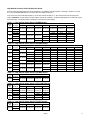
75--530.0 5H081891 A August, 2013 SELECT TION AND D INSTAL LLATION INSTRUC CTIONS high h altitude e gas pressure adjjustmentt and pres ssure sw witch kit forr models HD/HDB, H PD DP/BDP, P PTP, HDS/H HDC, PTS/B BTS, and P PTC/BTC WARN NING 1 1. All field gas piping must be e pressure/leak k tested prior to o operation. Never N use an open o flame. Us se a soap solution or equivalent e for te esting. 2 2. Gas supply shall be shut-o off and the elec ctrical power eeding with the conversion. disconnected before proce Failure to do o so could resu ult in fire, explos sion, electrical shock, or the e unit starting suddenly s resultting in injury. IM MPOR RTANT T 1 1. The use of this manual is specifically s inte ended for a qualified insttallation and se ervice agency. All installation n and service of these kits must m be perform med by a qualified insttallation and se ervice agency. 2 2. These instru uctions must als so be used in conjunction c with the Insttallation and Se ervice Manual originally o shipped with h the appliance e being convertted, in addition to any other accompanying g component supplier literature. M Modine’s gas-fired equipment standard s input ratings are ce ertified by CSA A or ETL. For elevations e abov ve 2,000 ft., AN NSI Z223.1 req quires ratings be b reduced 4 percent for ea ach 1000 ft. ab bove sea level. For units in Ca anada, CSA re equires that ratiings be reduce ed 10 percent at a elevations ab bove 2,000 ft. The high altitude adjustment instructions an nd pressure sw witch kits appea aring in this bulletin are for usse with units that will be installed over 2,000 0 ft. These m methods and kits s comply with both b ANSI Z22 23.1 and CSA re equirements. ection of the Proper Pres ssure and Kitt Sele To de etermine the prroper manifold pressure at altitude and if requiired, the proper combustion a air pressure sw witch kit, the full m model number o of the heater, th he fuel to be ussed, and the a altitude the unitt will be installe ed at must be kknown. Refe r to the unit serial plate or carton label to ob btain the essary informattion about the u unit. nece efer to the prop per gas Afterr obtaining this information, re presssure and selecttion charts. Th he pressure charts are differrentiated by ele evation, fuel typ pe, and countryy the produ uct is being insstalled in. The selection chartts are differrentiated by pro oduct type, altittude and fuel tyype. If conv verting from natural gas to propane gas a and operration at high a onversion altitude, both a propane co kit an nd a pressure e switch kit mu ust be used (iff appliicable). Selecction charts include the proper kit suffix, when n required. Man nifold Pressu ure Adjustme ent The iinlet pressure tto the unit musst be confirmed to be within n acceptable lim mits (6-7” W.C C. for natural ga as and 1114” W W.C. for propan ne gas) before opening the sh hutoff valve or the e combination gas valve mayy be damaged. ers for use with h natural gas have gas valve es factory Heate set a at 3.5” W.C. ma anifold pressure e at 7.0” W.C. iinlet presssure. Unitss for use with p propane gas are set for 10.0”” W.C. mani fold pressure a at 14.0” W.C. in nlet pressure. Insta allation above 2 2,000 ft. elevation requires ad djustment of manifold pressu ure as detailed in the following g pages. the m If a unit is to be installed at higher elevations AND co onverted from natural n gas to propane p gas op peration, a prropane convers sion kit must be e used in conju unction with th he pressure adjustment metho ods and pressu ure switch kits lissted herein. Fo or the Selection n and Installatio on Instructions fo or propane conv version kits for units with tubu ular heat exxchangers (HD D, HDB, HDS, HDC, H PTP, PTS S, BTS, PTC, orr BTC), please see the latest revision of Mod dine Bulletin 75 5-515. For the Selection and Installation Ins structions for prropane convers sion kits for uniits with clamsh hell heat exxchangers (PD DP or BDP), ple ease see the lattest revision off M Modine Bulletin 75-511. ANUAL IS THE E PROPERTY OF THE OWNER. THIS MA PLEASE BE SURE TO LEAVE IT WIT TH THE OWNE ER WHEN YOU U LEAVE THE JOB. for detailed information about the gas type and BTU content (heating value) before operating any heater. Tables 2.1 and 2.2 show the standard derated heating values (4% per 1,000’ of elevation in the USA and 10% between 2,001’ and 4,500’ elevation in Canada) of natural and propane gases at various altitudes. If the utility is supplying gas with heating values as shown in Tables 2.1 and 2.2, the manifold pressure should be set to 3.5 in. W.C for natural gas and 10.0 in. W.C. for propane gas. Derated BTU Content Gas and Manifold Pressure Calculation Some utility companies may derate the BTU content (heating value) of the gas provided at altitude to a value 3 3 other than 1,050 BTU/ft for Natural Gas or 2,500 BTU/ft for Propane Gas to allow certain heating appliances to be used with no manifold pressure adjustments. For this reason it is necessary that the supplying utility be contacted Table 2.1 – Natural Gas Heating Values at Altitude Gas Heating Values at Altitude (BTU/ft 3) USA CANADA Altitude (ft) 0‐2,000 1,050 1,050 2,001‐3,000 929 945 3,001‐4,000 892 4,001‐4,500 874 4,501‐5,000 856 856 5,001‐6,000 822 822 6,001‐7,000 789 789 7,001‐8,000 757 757 8,001‐9,000 727 727 9,001‐10,000 698 698 Table 2.2 – Propane Gas Heating Values at Altitude Gas Heating Values at Altitude (BTU/ft 3) USA CANADA Altitude (ft) 0‐2,000 2,500 2,500 2,001‐3,000 2,212 2,250 3,001‐4,000 2,123 4,001‐4,500 2,080 4,501‐5,000 2,038 2,038 5,001‐6,000 1,957 1,957 6,001‐7,000 1,879 1,879 7,001‐8,000 1,803 1,803 8,001‐9,000 1,731 1,731 9,001‐10,000 1,662 1,662 Values shown are for 3.5 in. W.C. manifold pressure , for other BTU content values (available from local utility) use Equation 2.1 to calculate manifold pressure. Values shown are for 10.0 in. W.C. manifold pressure , for other BTU content values (available from local utility) use Equation 2.1 to calculate manifold pressure. When installed at altitudes above 2,000', a pressure switch may need to be changed. Refer to Tables 3.1 through 4.2 to determine if a switch change is required. Gas Heating Values are derated 4% per 1,000' of elevation in the USA and 10% between 2,000' and 4,500' elevation in Canada in accordance with ANSI Z223.1 and CSA-B149, respectively. If the heating value of the gas being supplied is different than the values shown in Tables 2.1 and 2.2, use the following equation to determine the appropriate manifold pressure for the altitude and gas heating value being supplied. Equation 2.1 – Manifold Pressure for Derated Gas Where: MPACT ManifoldPressure in.W.C. atAltitude–Manifoldpressuresettingfortheheaterbeinginstalled BTUTBL BTU/ft3contentofgas‐obtainedfromTables2.1or2.2 whicheverisapplicable BTUACT BTU/ft3contentofgas‐obtainedfromtheutilitycompany MPSL ManifoldPressure in.W.C. ,atSeaLevel–use3.5”W.C.forNaturalGasand10.0”W.C.forPropane NOTE: Only the primary Manifold Pressure should be adjusted on units equipped with two-stage or modulating gas controls. No adjustments to the Low Fire Manifold Pressure are necessary on these units. High Altitude Pressure Switch Kit Selection In some instances, the combustion air proving (pressure) switch may need to be changed depending upon the unit style, model size, and installation altitude. The example selection procedure shown on the following page, along with the associated tables, will guide the installer as to when a High Altitude Pressure Switch is required and which switch is to be used. 2 75-530 High Altitude Pressure Switch Kit Selection Guide Example: select the appropriate kit for an HD 125AS0111 for installation at 6,000’ elevation. Referring to Tables 3.1 through 3.5, it can be identified that Table 3.1 should be used as it applies to HD units. In the column for 5,501-6,500 feet elevation, it can be seen that the kit suffix is -4. All conversion kits have the same base number (3H037813), only the suffix of the part number changes by model size. All kits are appropriate for use with both natural and propane gas. The full kit number is 3H037813-4 and the item code is 68408. Table 3.1 – High Altitude Switch Kits for HD/HDB Models Model Size 30-60 75 100 125 U.S.A and Canada Kit Details 2,001-4,500 ft 4,501-5,500 ft 5,501-6,500 ft 6,501-7,500 ft 7,501-8,500 ft 8,501 - 9,500 ft 9,501-10,000 ft Kit Suffix Not Required Not Required Not Required Not Required Not Required Not Required Not Required Not Required Not Required Not Required Not Required Not Required Not Required Not Required Not Required Not Required Item Code Kit Suffix Item Code Kit Suffix Item Code Kit Suffix Item Code 0001 0001 0001 68405 68405 68405 0004 0004 0004 0004 68408 68408 68408 68408 0004 0004 0004 0004 0004 68408 68408 68408 68408 68408 Table 3.2 – High Altitude Switch Kits for HDS/HDC Models Model Size 30 45 60 75 100 125 U.S.A and Canada Kit Details 2,001-2,500 ft 2,501-4,500 ft 4,501-5,500 ft 5,501-6,500 ft 6,501-7,500 ft 7,501-8,500 ft Kit Suffix -2 68406 -3 68407 -3 68407 -3 68407 -4 68408 -3 68407 -3 68407 -5 68409 -3 68407 -5 68409 -5 68409 Not Required Not Required Not Required Not Required Not Required Not Required Not Required -4 68408 Not Required Not Required Item Code Kit Suffix Not Required Item Code Kit Suffix Not Required Item Code Kit Suffix Not Required Item Code Kit Suffix Item Code Kit Suffix Item Code -5 68409 -6 68410 -7 68411 -7 68411 -4 68408 -4 68408 -10 68414 -10 68414 -11 68415 -11 68415 -4 68408 -4 68408 8,501 - 9,500 ft 9,501-10,000 ft -10 68414 -10 68414 -11 68415 -11 68415 -4 68408 -4 68408 -10 68414 -11 68415 -11 68415 -11 68415 -4 68408 -4 68408 Table 3.3 – High Altitude Switch Kits for PDP/BDP Models Model Size 150-400 U.S.A. and Canada Kit Details 2,001-4,500 ft 4,501-5,500 ft 5,501-6,500 ft 6,501-7,500 ft Kit Suffix Not Required Not Required Not Required Not Required Item Code Table 3.4 – High Altitude Switch Kits for PTP/PTS/BTS Models Model Size U.S.A. and Canada Kit Details 2,001-4,500 ft 4,501-5,500 ft 5,501-6,500 ft 6,501-7,500 ft Kit Suffix 150-300 Item Code Not Required Not Required Kit Suffix 350 Item Code Not Required Not Required Kit Suffix 400 Item Code -9 68413 -9 68413 Not Required Not Required -8 68412 -9 68413 -8 68412 -9 68413 Table 3.5 – High Altitude Switch Kits for PTC/BTC Models Model Size 55-310 U.S.A. and Canada Kit Details 2,001-4,500 ft 4,501-5,500 ft 5,501-6,500 ft 6,501-7,500 ft Kit Suffix Not Required Not Required Not Required Not Required Item Code 75-530 3 Installation 1. Read these instructions carefully. Failure to follow instructions can damage product or cause a hazardous condition. 2. Adjustment of the manifold pressure and installation of the pressure switch (if applicable) must be performed by a qualified service person. The qualified service agency performing this work assumes responsibility for the proper conversion and adjustment of this appliance. 3. This procedure requires the following: A conversion rating plate (5H0807146005) A pressure switch (see Tables 3.1 – 3.5) 4. On the High Altitude Conversion Label included with these instructions, write the new manifold pressure at both high and low fire, elevation of installation, derated input, and derated output at high fire in permanent marker. 5. Remove the access panel to the heater. 6. For units requiring a pressure switch change (refer to Tables 3.1 through 3.5), disconnect wires and remove screws. Install new switch and attach wires. Note: wires are interchangeable. 5. Repeat the process for low stage heating by turning the thermostat setting down to call for low stage heating. Verify the manifold pressure setting is correct per the I&S manual that came with the unit. Adjust as necessary using the instructions in the I&S manual. 6. There are no adjustments that can be made to the burner flame on units with tubular heat exchangers. Units with clamshell heat exchangers may have air shutters for flame adjustment. If the flame is lifting or rising above the burner port, loosen the thumb screw on the air shutter and slide it forward toward the mixer tube. If the majority of the flame is yellow, move the air shutter back away from the mixer tube. Some yellow in the flame is acceptable on propane flames as long as no carbon (black soot) is being formed. For more specific flame control adjustment instructions, see the I&S manual that came with the unit. 7. Turn the heater off and replace the inlet and outlet pressure tap plugs. 8. Place the heater back into service and leak test the inlet and outlet pressure tap plugs, as well as the connection between the gas valve and the manifold piping and supply piping to the gas valve. 7. Affix the High Altitude Conversion Label that came with the unit or kit on the heater near the serial plate on the same panel as the common replacement parts label. Check 1. See the original rating plate for the unit heater’s rated input and verify by checking the correct main burner orifice size and manifold pressure. This information is presented in the unit Installation & Service (I&S) manual. 2. Remove the inlet and outlet pressure tap plugs and place pressure taps on both the inlet and outlet pressure tap of the gas valve. 3. Connect a pressure-measuring device capable of reading inches of water column onto the inlet and outlet pressure taps. 4. Follow lighting instructions on the unit. Turn up thermostat setting to call for high stage heating. After the main burners light, measure the outlet (manifold) pressure of the combination gas valve. The pressure should be as determined in Tables 2.1 and 2.2 or as calculated with Equation 2.1, whichever is applicable. The outlet pressure can be adjusted at the valve’s regulator. Turning the adjustment clockwise will increase the outlet pressure, while turning it counterclockwise will decrease the pressure. Modine Manufacturing Company has a continuous product improvement program, and therefore reserves the right to change design and specifications without notice. Commercial Products Group Modine Manufacturing Company 1500 DeKoven Avenue Racine, WI 53403 Phone: 1.866.828.4328 (HEAT) www.modinehvac.com Modine Manufacturing Company 2013