1
USER GUIDE
Hardware Reference
Matrix3 Audio Show Control System
Edition: 2007-09-18 for CueStation 4.6.0
LCS SERIES
Meyer Sound Laboratories Inc
2832 San Pablo Avenue
Berkeley, CA 94702
www.meyersound.com
T: +1 510 486.1166
F: +1 510 486.8356
© 2007
Meyer Sound Laboratories Inc.
© 2007 Meyer Sound. All rights reserved.
Hardware Reference
The contents of this manual are furnished for informational purposes only, are subject to change without notice, and
should not be construed as a commitment by Meyer Sound Laboratories Inc. Meyer Sound assumes no responsibility or liability for any errors or inaccuracies that may appear in this manual. Except as permitted by applicable
copyright law, no part of this publication may be reproduced, stored in a retrieval system, or transmitted, in any form
or by any means, electronic, mechanical, recording or otherwise, without prior written permission from Meyer Sound.
CueStation, CueConsole, LCS Series, Matrix3, Wild Tracks, VRAS and all alphanumeric product names are trademarks
of Meyer Sound. Meyer Sound and SpaceMap are registered trademarks of Meyer Sound Laboratories Inc. (Reg.
U.S. Pat. & TM. Off.). All third-party trademarks mentioned herein are the property of their respective trademark
holders.
Printed in the U.S.A.
Part Number: 05.164.072.01 rev.A
Table of Contents
LX-300 Start Up Routine
7
Overview
A. Power-On Self Test
B. Hardware Initialization
C. System Firmware Startup
EtherTracks Startup
Firmware Updates
11
Before You Begin
Firmware Update Procedures
Special DSP ID Codes
Matrix3™ Repair Procedures
19
Overview
Replacement of Power Fuse
Removal and Installation of Modules
LX-300 Maintenance
23
Overview
Recommended Schedule
Inspection and Maintenance Procedure
Operational Testing
Hardware Specifications
25
LX-300 Specifications
Power Requirements
Component Specifications
LX-300 Error Codes
43
Status LED Blink Codes
Frame Status Error Codes
Frame Status Error Messages
CueStation Log Window Messages
Appendix
47
Returns Policy
Shipping Address
5
6
LX-300 Start Up Routine
Overview
A. Power-On Self Test
B. Hardware Initialization
C. System Firmware Startup
EtherTracks Startup
7
8
8
9
10
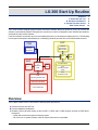
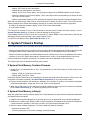
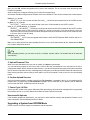
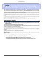
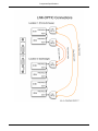
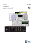
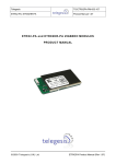
The LX-300 contains a digital signal processor and built-in software. When you power-on ("boot") an LX-300, this
software is automatically loaded. During the boot, it performs a number of diagnostic tests, initializes the hardware,
and loads the latest control software.
If the boot software encounters any non-recoverable (fatal) errors, it will attempt to display the error. The following
boot sequence description should assist you in identifying at which point the error occurred and what caused it.
ELC
COS
LX-ELC
EtherTracks
Ethernet Port
LX-COS
ComSync
Serial Ports
PPC
ELC
RAM
DSP
EPROM
1.6.1
TI
320C6701
DSP
ELC Boot Flash
DSP
RAM
ELC
Operating System
Flash
ELC
IP Address Flash
DSP
Operating System Flash
User Boot Script Flash
User Project Flash
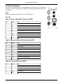
Overview
The LX-DSP module in the LX-300 does the following when powered-on:
A. Performs a Power-On Self Test.
B. Performs hardware initialization.
C. Reads the Frame ID switch setting on the LX-DSP, LX-EXP, and LX-VRA modules, and then for DSP IDs 01
through 32:
• Loads and executes the system firmware program.
• OR, if there is no system firmware, waits for system firmware to be uploaded.
7
A. Power-On Self Test
For all other Frame IDs, the DSP performs special functions as described in Special DSP ID Codes (p. 16).
These steps are described in detail in the sections that follow.
A. Power-On Self Test
During the first stage of power-on boot, the LX-DSP processor module waits for the LX-300 power and bus signal
conditions to stabilize. It then tests its main SDRAM memory circuits and loads the next stage of boot software.
1. Power is turned on.
2. Wait for the LX-300 circuits to fully power-on and stabilize.
• Wait 1/2 second. The Watchdog LED is red.
• Start a watchdog timer that will turn the LED red if the system stalls.
• If the Watchdog LED does not turn green, the LX-300 is completely non-functional and must be returned to
Meyer Sound for repairs.
3. Test the SDRAM memory.
• Green Watchdog LED: success.
• Red Watchdog LED: failure.
4. Initialize Hardware. Proceed to B. Hardware Initialization (p. 8), below.
POST Failure
In the event of a POST error, rebooting the LX-300 may resolve the issue. Repeated failure indicates the LX-DSP
processor module is non-functional. Replace the LX-DSP with a known-good module. Return the non-working
module to Meyer Sound for repairs.
Multiple LX-DSP failures indicate a problem with the LX-300 itself. Replace the LX-300 with a known-good LX-300.
You may re-use the modules from the non-working LX-300, but they should be treated as suspect until proved good
(they may have been damaged by the non-working LX-300.) Return the non-working LX-300 to Meyer Sound for
repairs.
Multiple LX-300 failures indicate a problem with the facility power system. This is a situation beyond the scope of
this manual. Facility power problems may result in non-warrantable damage to your LX-300s.
B. Hardware Initialization
1. Prepare boot monitoring: set Watchdog LED to green.
When possible, the LX-300 will display an error code when the boot process fails. It does this by blinking the
Watchdog LED and by using the Frame Status display.
Most errors will display an two-digit error code in the Frame Status ("IE" plus two numbers).
There are several errors that make it impossible to use the Frame Status display. For these errors, the Watchdog
LED will repeatedly blink the error code, with a pause between each cycle. The number of green-red blinks corresponds
to the error code.
Consult the LX-300 Error Codes (p. 43) section of this manual for trouble-shooting advice for known failure modes.
The cause of a failure that stalls the system, such that errors can not be displayed, can not be directly determined.
In such cases, contact Meyer Sound LCS Series™ customer support for assistance.
2. Perform various vital hardware initializations.
• Green Watchdog LED: initialization is proceeding successfully.
• Red Watchdog LED: system initialization has stalled.
• Blinking Red-Green LED: initialization has failed. See LX-300 Error Codes (p. 43).
There are two possible failures that do not stop the system at this point. The error messages will be scrolled across
the Frame Status. They refer to "DMA0" and "DMA1". See LX-300 Error Codes (p. 43) for details.
3. Enable front panel display.
8
C. System Firmware Startup
•
•
•
•
Display "INIT" briefly on the Frame Status.
Display all front panel lights for one second.
Display "E1V6" on the Frame Status. The two digits correspond to the EPROM software version number.
Show the Frame ID in the Frame ID display. This is a two-digit number corresponding to the Frame ID value
set on the LX-DSP module.
• Show the appropriate Expansion LEDs, indicating the expansion slots which have modules installed in them.
When the boot process has made it this far, it becomes easier to identify any failure points. The LX-300 can now
display messages in the Frame Status display, allowing you to monitor the boot process as it progresses.
4. Initialize the expansion modules: display "LCS3" on the Frame Status display.
5. Load system firmware.
For Frame IDs 01 through 32, the LX-300 will attempt to load the system firmware from flash memory. Go to C.
System Firmware Startup (p. 9), below, to continue following the boot process.
If the software load fails (or if the Frame ID is 33 through 79), display "REBO" on the Frame Status, and blink the
Watchdog LED five times repeatedly, with a pause between cycles.
For other IDs, see Boot ID codes Special DSP ID Codes (p. 16).
C. System Firmware Startup
The boot process takes one of two paths at this point, depending on the contents of the system flash memory:
• When the system flash memory is empty (no firmware exists), the LX-300 initializes its LX-LNK module and awaits
a firmware upload. Unless a fatal error occurs, an animated -EP- will be displayed in the Frame Status.
• When the firmware is available, the LX-300 attempts to load it. Unless an error occurs, the hardware will be further
initialized. If an LX-ELC EtherTracks module is installed in the LX-300, it will be loaded with the Linux server.
If the boot sequence completes successfully, an animated -OK- will be displayed in the Frame Status.
The following two sections describe these boot paths in detail.
If System Flash Memory Contains Firmware
1. Display "FILu" (uncompressed file) or "FILc" (compressed file) on the Frame Status for 2/10th seconds, then
load the file.
• Display "LOAD" for 1/10th second: success
• Display "badF" and "IE14": failure.
Erasing the System Flash memory and reloading the firmware may help resolve this problem. Please refer to the
instructions for firmware upgrades in the Matrix3 Repair Procedures (p. 19) section of this manual.
2. Execute firmware program and initialize the hardware. This sequence is similar to the hardware initialization
process described above, except that "E1V6" and "LCS3" are not displayed.
3. When the LX-300 has an LX-ELC EtherTracks module installed, the boot sequence will continue as described
below, EtherTracks Startup (p. 10), before progressing to the next step.
If System Flash Memory is Empty
When the system flash memory has been erased, the LX300 falls back to a simple software subsystem initialization
and awaits its firmware upload.
1. Initialize control software subsystems. In the event of an error, the appropriate error code will be displayed.
2. Initialize the LX-LNK module. Display "LINK" on the Frame Status, and update the link module FPGA program,
if newer software is available. In the event of a failure, the Frame Status will display "IE12".
3. Start the control software subsystems. The Frame Status will show the following:
• Display an animated "-EP-".
• Scroll any messages, such as error messages, across the display.
9
EtherTracks Startup
4. Await EPROM upload. Refer to the "Matrix3 Repair Procedures" section for more information.
Subsystem Initialization Failure
Subsystem initialization failure will usually result in a general system failure. The system will display an error message
(see LX-300 Error Codes (p. 43)) and "REBO", and flash the Watchdog LED red and green.
Subsystem failure usually indicates a failure in the LX-DSP or LX-LNK modules. Some subsystems can fail without
causing a system failure. If the EtherTracks, internal time code, or SMPTE time code subsystems fail, the system
at large can continue to work without these features.
EtherTracks Startup
In systems that have an LX-ELC EtherTracks module installed, the boot sequence will continue as follows:
1. Initialize the LX-ELC EtherTracks module, and display "ETRX" on the Frame Status.
2. Load the boot program. An error message will be displayed if a failure occurs.
3. Load LX-ELC Linux kernel. When successful, the Frame Status will alternate between displaying the MAC address
and the IP address of the LX-ELC module. An error message will be displayed if a failure occurs.
4. Start the Linux EtherTracks server.
5. Start LX-ELC communications, and continuously perform the following:
• Monitor system conditions.
• Display "/OK\" twirlies in the Frame Status.
• Scroll any messages across the Frame Status.
• Update time code and meter displays.
• Update communication LED displays.
10
Firmware Updates
Before You Begin
Firmware Update Procedures
Special DSP ID Codes
11
12
16
The LX-DSP, LX-ELC, LX-VRA, and LX-EXP modules load operating system files into RAM during power-on. These
files are stored in flash memory on each of the modules. Because these files are stored in the module, they are referred
to as “firmware”. The version number for the firmware files and CueStation must match. If you upgrade to a new
version of CueStation, you must also upgrade all firmware files.
Firmware files are sent from the Mixer Configuration window in CueStation using the “Upload Firmware” command.
CueStation 4 requires an Ethernet connection to an LX-ELC module. If the flash memory of the LX-ELC module has
been erased you will need an LX-COS comm/sync module and Virtual LX in order to upload firmware.
In a multiple LX-300 system connected with LX-LNK Link modules, all LX-300s are upgraded simultaneously.
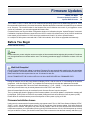
Before You Begin
Please read the following:
Note
Please make sure you are using the most recent version of documentation before beginning this procedure. Procedures
may change between one release and the next. The following procedures apply to CueStation versions 4.6.0 and
earlier.
Wait Until Complete!
Do NOT power-off before the update is complete! Firmware files are automatically transferred to the appropriate
LX-300 modules. The transfer will take from a few seconds to several minutes. For serial transfers of the LX-ELC
EtherTracks files the time required can be over 15 minutes for each file.
DO NOT POWER-OFF THE LX-300s UNTIL ALL LX-300s HAVE UPDATED ALL FIRMWARE FILES
During the transfer, the LX-300 Frame Status will display "XFRx", with the value of "x" incrementing as the transfer
progresses. It will then display "WAIT" as it updates the firmware and checks that the update was successful.
The update is complete ONLY when the Frame Status displays "...FILE... GOOD...". It may take several minutes to
reach this point and there may be a delay between the words "FILE" and "GOOD".
Several firmware flash files may be contained in each firmware file sent from the computer.
The Log window will show the progress of the firmware updates. As each file update is completed a message will
be displayed: "[INFO] Write to FLASH file succeeded (Changes will take effect after the frame is power cycled)".
Please allow ten seconds between power-off and power-on when power cycling a LX-300.
Firmware Installation Issues
Under some circumstances the firmware transfer may appear to stall. The LX-300 Frame Status will display "XFRx",
"WAIT", or -OK-, but the display will be frozen. This is a normal part of the firmware update. If this state continues
longer than four minutes, the system may have actually stalled. If that is the case and the stall occurred before
transfer was complete, you may be able to power cycle the LX-300 and recover. If the LX-300 does power up correctly
and you are able to connect, you should use the Erase Flash command to clear the flash memory and then try up11
Firmware Update Procedures
loading the file again. If you use the Erase Flash command for the EtherTracks module and then switch off the LX300 (or power fails), You will have to use VirtualLX and a serial connection to an LX-COS module to recover.
If part of the erase procedure had already been started, the flash memory could be corrupted or incomplete and the
LX-300 will not start up properly. To remedy this situation you must force an erase of the problem firmware file using
the LX-DSP module ID switch. See Special DSP ID Codes (p. 16).
Firmware Update Procedures
Upgrading a Matrix3 System Running CueStation 4
If you are trying to upgrade a system running CueStation 3 firmware, please see section Upgrading a System
Running CueStation 3 (p. 14).
1. Download Firmware Files
The most recent version of the firmware is available at http://www.lcsforums.com, or by contacting [email protected]. When downloading firmware files, you will have either one .zip file containing all firmware
files, or four separate .zip files. Save them to an easily accessible location on a computer running a CueStation client.
You can either unzip them and upload the .csf files, or upload the .zip file(s).
2. Connect CueStation to the LX-300
Start CueStation and connect to the server of the system you wish to upgrade. You can use a newer version of
CueStation 4 to upload new firmware. You may get an alert message in the log when you connect, warning you that
the version numbers do not match. As long as all you are doing is uploading firmware, you can proceed. Open the
Mixer Configuration window. Save the current project and configuration if you haven't yet done so.
3. Disable LX-300 Auto Start
As part of uploading firmware, the system will need to be power cycled. If an Auto Start project is enabled, it is best
to disable it before proceeding:
1. Select LX-300 Auto Start... from the Configuration menu.
2. In the dialog box that appears, open the menu labeled "On Power Up:", and select Do Not Auto Start.
3. Click on the Save Settings button, and then close the dialog box. The log will then report "Boot Script save to
disk SUCCEEDED".
At this point, you should power cycle all LX-300s in the system.
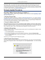
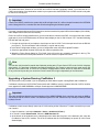
4. Select Firmware Files to Upload
After the LX-300s have finished the startup procedure and are displaying the "-OK-" twirlies on the front panel display,
open the Mixer Configuration window. In the Configuration menu, select Upload Firmware... You will see a warning
like this:
12
Firmware Update Procedures
After you click OK, a blank configuration will be sent to the hardware. This is to prevent audio processing while
firmware is uploaded.
Another dialog box will appear, allowing you to locate the firmware file(s).
All modules should be using the same firmware version as CueStation. There are five firmware files in each release:
lx300_vx_x_x_xx.csf
(where "x_x_x_xx" is the version number) The lx300___.csf file has two firmware files for the LX-DSP module.
et_boot_v_x_x_x_xx.csf
The et_boot___.csf file is a very small file that is the first of 3 files needed for the LX-ELC module.
etrx1_x_x_x_xx.csf, etrx2_x_x_x_xx.csf
The etrx1___.csf and etrx2___.csf files are very large and are the rest of the files needed for the LX-ELC module.
All three of these must be sent to the ELC module or it will not run correctly. If only part of them are sent, you
may have to force an erase of the ELC module and upload via a serial connection to an LX-COS module in order
to recover. (See LX-300 ID Codes)
lx300exp_vx_x_x_xx.csf
The lx300exp___.csf file is used to upgrade the firmware in both LX-EXP Expansion DSP modules, and for LXVRA VRAS modules.
Make sure to select all five files when uploading firmware, or one .zip file that contains all files. Hold down the Shift
key to select multiple files at once.
Tip
When uploading firmware, you can select a .zip file, or multiple .zip files, and the .csf firmware files will be extracted
automatically.
5. Upload Firmware Files
When you have selected the files you wish to upload, click Open to upload them.
You can watch the progress on the front of the LX-300 as the files are transferred. You must wait for all files to
complete the transfer and be written into flash memory. If you shut off the power before the process has completed,
the LX-300 will not operate correctly. If this happens you may have to use the special DSP module ID codes to erase
flash memory and then connect using a serial cable to an LX-COS module in order to recover. See the following
part B.
6. Confirm Upload Success
Once the firmware upload is complete, there will be File Complete... messages in the log. If you uploaded all five
firmware files, you should see six File Complete messages: one for each DSP in your system, plus an additional
one from the main DSP. All DSPs should now be online.
7. Power Cycle LX-300s
Power cycle all LX-300s in the system. When they finish powering up, there should be messages in the log reporting
the firmware version, so you can double-check that the firmware upload succeeded.
Unsuccessful Uploads
If the firmware upload was unsuccessful, you may have to erase the flash memory and upload the firmware over a
serial connection. See the following section for details.
Upgrading a System from EPROM Mode
Please contact LCS Series support for assistance with this operation.
13
Firmware Update Procedures
This assumes that the firmware in the LX-DSP and LX-ELC has been completely erased. You must have an LXCOS Communication / Synchronization module in your system since the EPROM in the LX-DSP module is only able
to connect to a serial port.
Important
If there is an LX-EXP module in the system with an ID set higher than 32, it will not accept firmware while in EPROM
mode. Change the ID to a number less than 32 before beginning the firmware upload.
For newer computers without an RS-232 serial port, we have used the Keyspan USB to Serial adapter (USA-19QW).
Other adapters have been used successfully.
Even if the LX-ELC still has valid firmware, you will not be able to connect to the DSP. It is best to start with a known
good state. If you are in EPROM mode, the Frame Status display on the LX-300 will show "-EP-" and the Watchdog
LED will flash red and green.
1. Connect the serial port of your laptop to a serial port on the LX-COS. For this example we will use the RS-232
port (Port C). The communication rate is 38.4kbs, 1 stop bit and no parity.
2. In the Mixer Configuration window, go to the Configuration menu and select Upload Firmware...
3. Select the appropriate firmware file(s) and click Open to upload the files.
4. Watch the Frame Status display for "File Good", there will not be any completion messages in the log. The
EtherTracks firmware usually takes between 15 and 20 minutes to upload over serial.
Note
You can also verify that the file transfer has finished by looking at the "Frame Control" LED on the LX-300. It displays
serial activity. If is dark then CueStation has finished sending the file. Please be aware that any serial activity will
light the Frame Control LED, so if there is a CueMixer compact Matrix3 control surface or other device connected
to any of the serial ports they can cause the Frame Control LED to light independently of the file transfer.
Upgrading a System Running CueStation 3
This information is only needed if you are upgrading an older Matrix3 system running BeOS and CueStation 3.
CueStation 4 requires an LX-ELC EtherTracks module with 128MB of memory. Systems with older LX-ELC modules
must upgrade the 64MB SODIMM to a Meyer Sound-approved 128MB SODIMM.
Important
There are two different physical memory mappings of the 128MB SODIMM. Only a two bank type setup as 8MB by
16b will work with the LX-ELC module. The minimum speed is PC-100. Please use only memory modules provided
by Meyer Sound.
CueStation 4 client can not directly connect to a LX-300 running version 3 firmware. To make a connection you must
use VirtualLX.
1. Open CueStation 4, and select Network > Server > localhost (127.0.0.1).
2. In VirtualLX, enable Show Details. Select the HSB Simulator tab.
3. At the bottom of the window there is a drop down menu and a data entry box. In the data entry box, enter the
IP address of the LX-ELC module. This is the IP address that the LX-300 displays on power up in the Frame
Status display.
14
Firmware Update Procedures
4. In the drop-down menu, select Use TCP Connection. An alert box will open with a "System Reset Warning".
This is a normal caution. Click Yes.
5. In CueStation 4 open the Mixer Configuration window. Select Configuration > Upload Firmware. Make sure
that you comply with the instruction in the alert box that opens and then click OK.
6. A file requester window will open. Navigate to the location with the CS4 firmware files.
Note
Files can be sent in any order as long as all of them are sent before power-cycling the LX-300 The order listed here
goes from the shortest file to the longest.
7. Select the first file: et_boot-yyyymmdd.csf. This is a very small file and will upload in only a few seconds. If
possible, watch the front of the LX-300 for the acknowledgment "File Good".
8. CueStation 4 will display an Alert box cautioning you to wait for file upload to complete. Click OK.
CS3 will not be able to send a message to CS4 so you will not see an acknowledgment in the log window that the
file upload was successful.
Note
While it is not necessary, if you have a BeOS computer connected to the Matrix3 system during this upgrade, you
will see the CS 3 messages that confirm when Write to FLASH has succeeded.
9. Select the second file: lx300-yyyymmdd.csf. This file will take longer to upload and it has two parts that must
report "File Good". You must wait for both "File Good" messages.
10. If you have an Expansion DSP module, LX-EXP, or a VRAS module, LX-VRA you need to select lx300expyyyymmdd.csf as your third file.
11. The next files that need to be uploaded are the main firmware for the LX-ELC module. With Wild Tracks 4, the
size of the firmware file has grown to the point where it had to be split into two parts.
The first part is etrx1--2.4.23-yyyymmdd.csf. This will take some time to upload. Once you see "File Good" on the
Frame Status, upload the second part.
The second part is etrx2--2.4.23-yyyymmdd.csf. This will take some time to upload. You must wait for File Good to
be displayed and this will be a number of minutes, often several times longer than the wait for the first part of the
main EtherTracks firmware. Once you see "File Good", there is only one more file to upload.
12. The last file that has to be uploaded is a configuration for the EtherTracks module. In the Mixer Configuration
window, select Frame 1.
13. Set the Slot that has the LX-ELC EtherTracks module installed to EtherTracks. Note that the (Master) setting
is used for an LX-ELC module in Frame ID 01, while the (Slave) setting is used for any module that is in a LX300 with a higher ID number.
14. Enter the IP address for the module. Check the Send box. Then choose Configuration > Send Configuration
to Frames.
15. Once Configuration has been sent, go to VirtualLX and change the Connection to LX-300 in the drop-down
menu to use the built-in simulator. If you don’t do this, then when the LX-300 is re-started, VirtualLX will take
over the firmware running in the LX-ELC module.
16. You can now power-cycle the LX-300s to boot into version 4.6.0. Remember to leave the power off for at least
10 seconds before switching it back on again.
15
Special DSP ID Codes
Special DSP ID Codes
The ID switch on an LX-DSP module may be used to force the LX-300 to erase flash memory areas in the DSP,
EXP, and ELC modules. You may need to do this if flash memory has become corrupted, or if there is a problem
after uploading system flash. Both situations are rare, and erasing flash memory is not required in normal operation.
Try the Erase Flash commands first as they will allow you to erase and then replace flash files without requiring a
serial connection to re-load system and ELC flash files.
It is important to know that the operating system for the DSP, EXP, and ELC modules is loaded into RAM during
startup. You can erase the flash memory and the LX-300 will continue to run until power is switched off. If the firmware
files are not in flash, the next time the LX-300 is powered up, there will be no operating system to load and the
system status display will show “/EP\” to indicate that the LX-300 is operating from diagnostic code in the EPROM.
Normal operation will not be possible until the operating system has been re-loaded into flash memory and the LX300 power cycled.
There is also a diagnostic setting of the ID to force the LX-300 to run from EPROM. If you set the Frame ID switch
to 00, flash memory will be bypassed during the startup procedure and you will be running in EPROM mode. To
restore normal operation, return the switch to the proper ID and power cycle the LX-300.
There are four flash file locations that can be erased with an ID code setting on the LX-DSP module:
LX-ELC Flash
The LX-ELC Flash is the operating system for the Embedded Linux Computer that is the heart of the EtherTracks
module. When this is erased, you will not be able to make a network connection to the LX-ELC module. With
CueStation 4 there are four files that must be uploaded for the LX-ELC module to work. These are et-boot, etrx1,
etrx2, and a valid mixer configuration containing an Ethernet address. If any of these files are missing, the Frame
Status window will scroll a message listing the missing file.
System Flash
The System Flash is the operating system for each LX-300, and is stored in the LX-DSP module. If the system
flash is missing, the Frame Status will display /EP\ and the Watchdog LED will blink red and green. Please note
that if the ID switch is set to 00 or to an invalid id you will also get the /EP\ display. The system flash file is lx300.
This setting will also erase the operating system files in the LX-EXP and LX-VRA modules. The system flash
file for both of these modules is the lx300exp file.
NV RAM Settings
NV RAM is where some of the system flags are stored. These include the boot-from-flash flag. The erase command may not have an effect on systems running CueStation 4.
User Flash
User Flash is where the Auto Start project file is saved. You may need to erase this if there is a large project
file that has been saved to flash memory and you wish to upload a new project file that will not fit until the old
one is erased. There is an external subcue that will erase this area that should be tried first. The only time when
you will have to use the ID switch to erase User Flash would be if a project file has been saved, and set to Auto
Start, containing a logic flaw that crashes the LX-300. These are rare, but possible. It is also possible to create
a project file that contains a cue to reboot the LX-300 that automatically executes. In this case you would have
a LX-300 that was in an endless loop.
16
Special DSP ID Codes
Erasing Flash Memory
Caution
If you erase the LX-ELC flash, you must upload replacement firmware files to the LX-ELC module before it will work
again. You will need an LX-COS module for serial connection or a network connection to an LX-ELC module on
another LX-300 in the system that has not been erased. In CueStation 4 you will have to use VirtualLX in order to
connect to a LX-300 with an erased ELC module.
If you erase the System Flash, you must upload replacement firmware for the main DSP before the LX-300 will work
again. You will need a network connection to an LX-ELC module on the system or a serial connection to an LX-COS
module on the system.
1. Start with the LX-300 powered off.
2. On the rear of the LX-300 locate the LX-DSP module. It is in slot 0, in approximately the middle of the rear
panel. Make note of the Frame ID, so that it can be returned it to the original setting after this procedure. Valid
ID settings for normal operation of the LX-DSP module are in the range of 01 to 32.
3. Set the LX-DSP module ID switch to one of the following codes depending on the action desired.
ID
Action
83
Erase LX-ELC Flash
87
Erase System Flash
88
Erase NV RAM
89
Erase User Flash
4. Power the LX-300 on. You will see the Frame Status window on the front of the LX-300 display one of the following messages:
Message
Meaning
*EET
Erase EtherTracks Flash (ID 83)
*ESF
Erase System Flash (ID 87)
*ENV
Erase Non-volatile RAM (ID 88)
*EUF
Erase User Flash (ID 89)
5. After the Erase has completed, the status display will show "REBO" (for reboot). Power off the LX-300.
6. Set the Frame ID back to the original setting (01 to 32).
7. Power the LX-300 on.
If you have erased the System Flash, the system status display will show /EP\ indicating that the LX-300 is running
from the minimum operating system in the EPROM. You must reload the main DSP firmware to use the LX-300:
see Upgrading a System from EPROM Mode (p. 13) for instructions on performing this operation.
If you have erased the LX-ELC Flash, the system status display a series of messages listing the missing ELC flash
files. You must upload the missing files as well as sending a mixer configuration with the IP Address Send checked
in order to load an IP address into the module. The default IP address is set to 192.168.0.(100+Frame ID), so Frame
ID 01 would have a default IP address of 192.168.0.101.
17
18
Matrix3 Repair Procedures
Overview
Replacement of Power Fuse
Removal and Installation of Modules
19
19
20
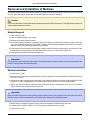
Physical repair of the Matrix3 system is limited to replacement of expansion modules.
Overview
Skills Required
• Removal of LX-300 from audio system.
• Removal and installation of expansion modules.
• Return of LX-300 to system, including cable re-connection.
Required Tools and Components
• Anti-static equipment, including a personal grounding strap.
• #2 Phillips screwdriver.
• Cable labels and pen.
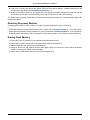
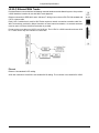
Replacement of Power Fuse
The LX-300 is protected from over-voltage conditions by a 2.5A, 240V slow-blow, 5◊20mm fuse. This fuse is located
in a fuse drawer beneath the power plug socket. The power plug must be removed to access the fuse.
1. Power off the LX-300. Remove power cable.
2. Open the fuse drawer, located immediately below the power plug socket.
The fuse drawer has two compartments: a spare fuse compartment, located at the front of the drawer; and the
working fuse compartment, located at the rear of the drawer.
3. Remove the failed fuse and replace it with the spare fuse.
Caution
If there is no spare fuse the LX-300 has experienced a fuse failure previously. Contact LCS Series technical support
for further instruction: the unit may be performing abnormally and may require advanced technical servicing.
4. Close the fuse drawer and plug in the power cable.
5. Power on the LX-300, and observe the System LED and Frame Status displays. A detailed description of the
boot process is provided in the LX-300 Start Up Routine (p. 7).
6. Within four seconds of power-on, the System LED must display and remain solid green (except after the first
all-indicators-on test, when it will momentarily flicker red). Wait for the LX-300 to finish booting.
The system has successfully booted with the Frame Status shows an animated "-OK-" message and the Status LED
displays solid green.
19
Removal and Installation of Modules
Removal and Installation of Modules
All modules must be installed to a valid slot position. Incorrect assignment of modules to slots may result in hardware
failure or poor performance, although the modules themselves will not be damaged.
Caution
Circuit card assemblies contain Electrostatic Discharge Sensitive (ESDS) components. Take appropriate precautions
when handling expansion modules.
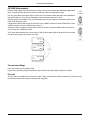
Module Removal
1. Power off the LX-300.
2. Label all cables attached to the module.
3. Disconnect all cables from the module.
4. Using a #2 Phillips screwdriver, completely loosen the module mounting captive machine screws. There are
two or four mounting captive machine screws, located at the top and bottom edges of the module. The captive
machine screws are permanently attached to the module.
5. Using gentle force, grasping the left-most pair of captive machine screws, pull the module from the frame. If the
module does not slide out easily, stop and find what is blocking it. Do not pry the module out!
6. Immediately place the module in an anti-static bag.
Important
Do not pull the module using the right-hand pair of mounting captive machine screws. They are not attached to the
module. Pulling on them will distort the panel.
Module Installation
1. Power off the LX-300.
2. Check the slot assignments. Modules will not function if assigned to an incompatible slot. Remove the blank
slot cover, if used.
3. Ensure the module engages the top and bottom rails. Modules that are not correctly aligned with the rails will
not install correctly. Using gentle force, slide the module firmly into place. Do not force the module!
4. Secure the mounting captive machine screws firmly and equally. Finger-tighten only: do not over-tighten.
Tighten the left-most captive machine screws first.
Important
Push the module using the left-most mounting captive machine screws. Do not apply force to the right-most captive
machine screws: they are not attached to the module and pushing them will distort the panel.
5. Attach cables, according to labeling. Ensure cables are snapped or fastened firmly into place.
6. If installing the LX-DSP, LX-EXP, or LX-VRA processor modules, set the Frame ID.
7. Power on the LX-300.
20
Removal and Installation of Modules
8. Power on the LX-300, and observe the System LED and Frame Status displays. A detailed description of the
boot process is provided in the LX-300 Start Up Routine (p. 7).
9. Within four seconds of power-on, the System LED must display and remain solid green (except after the first
all-indicators-on test, when it will momentarily flicker red). Wait for the LX-300 to finish booting.
The system has successfully booted with the Frame Status shows an animated "-OK-" message and the Status LED
displays solid green.
Restoring Processor Modules
If installing the LX-DSP, LX-VRA, LX-EXP, or LX-ELC processor modules, it may be necessary to:
• Erase and restore the System Flash firmware ("87"). Please refer to Firmware Updates (p. 11) for instructions.
• Erase and restore the EtherTracks Flash Memory ("83"). Please refer to Firmware Updates (p. 11) for instructions.
• Erase the User Flash Memory ("89"), clearing all cue automation programs. The procedure is described below.
Erasing Flash Memory
1. Record the Frame ID so that it can be restored after erasing flash memory.
2. Power-off the LX-300. Please wait ten seconds before power-off and power-on.
3. Set the Frame ID to "89" (Erase User Flash Memory).
4. Power-on the LX-300 and observe the front panel lights. Within one minute, the Frame Status will display
"DONE", followed by its "REBO" reboot message.
5. Power-off the LX-300 and restore the Frame ID to its original value.
21
22
LX-300 Maintenance
Overview
Recommended Schedule
Inspection and Maintenance Procedure
Operational Testing
23
23
23
24
Dust, heat, humidity and power surges are the most significant dangers to the system and its components. For best
performance, the Matrix3 should be operated in a cool, low-dust, low-humidity environment. In most operating environments, periodic inspection of the LX-300 will ensure its longevity.
Overview
Skills Required
Visual inspection of hardware; tightening of connectors; power-cycling of LX-300s.
Required Tools and Components
• #2 Philips screwdriver.
• Soft cloth and glass cleaner.
Recommended Schedule
In most environments, a monthly inspection will be adequate.
Where conditions allow for extreme temperatures, humidity or dust infiltration; or where there is a possibility of water
leakage; or where the system may be subjected to vibration, we recommend a weekly or even daily inspection.
Table 1. Inspection Schedule
Environment
Dry, cool, dust-free, no vibration
Inspection Frequency
Monthly
Concerns for temperature, humidity, dust levels, vibration Weekly or Daily
Possibility of burst water mains, flooding, severe vibration, Daily
extreme heat or humidity, high levels of dust
Inspection and Maintenance Procedure
1. Check that the ventilation blowers are working by feeling for airflow at each vent. The blower vents are located
on the front panel, to either side of the displays.
If there is low or no airflow, replace the LX-300 and return the non-functional chassis to Meyer Sound for servicing.
LX-300 replacement procedures are described in Matrix3 Repair Procedures (p. 19). Shipping instructions are
described in the Appendix (p. 47).
2. Inspect all cable connections made at the rear of the unit. All connectors must be secure in their sockets.
Tighten any connections that have become loose. Do not over-tighten.
If a module socket is damaged, replace the module. module replacement procedures are described in Matrix3 Repair
Procedures (p. 19).
3. Inspect the module and chassis mounting points. Each module is secured using two or four captive machine
screws located at the top and bottom edges of the module. Finger-tighten to snug the captive machine screws
firmly. Do not over-tighten.
23
Operational Testing
Important
Tighten the left-hand captive machine screws on double-width modules first, to prevent warping the panel.
The chassis will be secured to its rack using four captive machine screws, located at either edge of the front panel.
There may be optional mounting points at the rear of the LX-300. Tighten these as appropriate. Do not over-tighten.
4. You may choose to clean the front panel of LX-300s using ordinary glass cleaner. Dampen the cloth and wipe.
Do not use a dry cloth, as this may scratch the front panel displays.
Do not spray the front panel directly. The liquid may infiltrate the LX-300, causing unseen damage to internal components.
In exceptionally dusty environments, it is permissible to vacuum the LX-300s. Using an electrostatically grounded
vacuum, clean the rear panels first, followed by the front blower vents.
Do not use pressurized air to clean the unit. Pressurized air will drive dirt into mechanical connections.
Operational Testing
1. Power-cycle the LX-300 using the power switch. The switch is located toward the top-right of the chassis, when
viewed from behind.
2. Observe the front panel indicators during the boot process:
Within four seconds of power-on, the Watchdog Indicator must display and remain solid green (except after the first
all-lights-on test, where it will momentarily flicker red).
Several boot messages will appear in the Frame Status display.
There will be two all-lights-on tests. After the second test, the Frame Status display may show "LINK" for a relatively
long period.
3. Wait as long as one minute for the LX-300 to finish booting.
The system has successfully booted with the Frame Status shows an animated "-OK-" message and the Watchdog
displays solid green.
4. The LX-300 has failed its operational test if any of the following conditions applies:
• System takes longer than one minute to display the "-OK-" message.
• The "-OK-" message is not animated.
• The Watchdog indicator displays blinking red during any part of the boot process.
• The Watchdog indicator displays solid red or blinking red while the Frame Status displays "-OK-" .
24
Hardware Specifications
LX-300 Specifications
Power Requirements
Component Specifications
25
26
27
This chapter presents detailed electrical, mechanical and physical specifications for the Matrix3 and its modules.
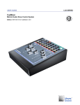
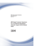
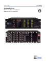
LX-300 Specifications
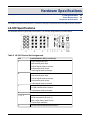
This illustration shows a typical Matrix3 back panel. The valid slot assignments are provided below.
Table 2. LX-300 Chassis Slot Assignments
Slot
Cards Allowed in Slot (* exclusively)
A
LX-AI8 analog audio input
LX-ML8 analog audio input
LX-ADAT digital audio input/output
LX-AO8 analog audio output
LX-AES digital audio input/output
B
LX-AI8 analog audio input
LX-ML8 analog audio input
LX-ADAT digital audio input/output
LX-AO8 analog audio output
LX-AES digital audio input/output
C
LX-AO8 analog audio output
LX-CBR CobraNet audio interface*
LX-AES digital audio input/output
0
LX-DSP system processor
1, 2, 3, 4
LX-LNK Link interconnect
LX-EXP expansion DSP (max. 3)
LX-ELC EtherTracks (Wild Tracks)
LX-VRA VRAS expansion
X
LX-COS communications/synchronization*
25
Power Requirements
Operating Environment
0° to 40° Celcius (32° to 100° Fahrenheit). 5% to 95% humidity, non-condensing. Low dust levels.
Warning
The internal temperature, as reported in the System Status window, is typically 10º C hotter than the operating environment. The Matrix3 may sustain damage if the internal temperature reaches 50º C.
Storage Environment
0° to 80° C (32° to 175° F). 5% to 95% humidity, non-condensing.
Power Consumption
AC, 47–70Hz, 100–250V, single phase. 150W maximum power required.
Fuse
2.5A, 240V slow-blow, 5x20mm.
Dimensions
W×H×D: 435×127×348mm (17.126×5×13.7 inches).
Weight
8.2kg (18lb) base configuration, with LX-DSP module and AC power cord.
Approximately 11kg (25lb) maximum weight with modules installed.
Shock/Vibration
8.2kg (18lb) base configuration, with LX-DSP system card and AC power cord.
Approximately 11kg (25lb) maximum weight with cards.
Heat Dissipation
150W maximum.
Racks/Enclosures
Standard 19” rack mount. All four mounting points on the front panel must be secured. Minimum 10cm (2.5 inch)
unobstructed air space behind and in front of each LX-300. No air space requirements above and below each LX300.
Racks shall be secured to floor and ceiling, to prevent tip-over, grounded against electrical shorts, and rated for
support of a minimum 150% of the weight of the equipment mounted on the rack.
Power Requirements
Each LX-300 requires an AC power source within 2 meters. The receptacles must have three-prong grounding, with
ground connected to protective earth.
The power supply must provide 100–250V, 47–70Hz, single-phase AC power. The power supply must be protected
by a 20A circuit breaker.
It is recommended that the power supply be EMI/RFI filtered, and protected against power surges. An Uninterruptible
Power Supply is recommended. It is further recommended that the overall power supply system be Ground Fault
Interrupt protected, as further precaution against electrical shock. The LX-300 chassis uses a standard IEC power
connector.
26
Component Specifications
Table 3. LX-300 IEC AC Power Connector
Pin
Name
1
Hot
2
Ground
3
Neutral
Component Specifications
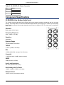
LX-ML8 Mic/Line Analog Audio Input
The LX-ML8 provides eight balanced XLR audio inputs with software-controlled microphone and line level gain
settings. The analog audio is converted to 24bit/48kHz digital data for processing by the LX-DSP. Up to two analog
input cards (for a total of sixteen input channels) can be used in a single LX-300. The cards must be installed in
Slots A or B.
Channels
Eight analog mic/line inputs.
Frequency Response
20Hz —20kHz (+/- 0.5dB)
Sampling
24bit/48kHz
Dynamic Range
109 dB (+26dBu, 20 kHz BW)
THD+N
<0.001% (+26dBu, 20-20kHz)
EIN
-125dBu (22kHz BW, max gain, Rs=150 ohms)
Crosstalk
-110dB (20-20kHz, +26dBu, channel-channel)
CMRR
-60dB (20-20kHz, -57dBu)
Input Load Impedance
9.2k ohms (balanced line-to-line)
Gain Settings for Full Scale
+26dBu, +16dBu to -57dBu in 1dB steps
Phantom Power
+48VDC at 10mA, switched per channel
27
Component Specifications
Pin-outs: LX-ML8 Balanced Female XLR
Pin
Name
Use
1
GND
Shield
2
Signal+
+Analog balanced input
3
Signal-
-Analog balanced output
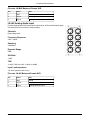
LX-Ai8 Analog Audio Input
Provides eight balanced-XLR analog audio signal inputs. Performs 24bit/48kHz digital
conversion with three conversion scaling settings.
Channels
Eight analog inputs.
Frequency Response
20Hz —20kHz.
Sampling
24bit/48kHz.
Dynamic Range
98dB.
S/N Ratio
-74dB.
THD
<0.005% THD from 20Hz - 20KHz at +26dBu
Input Load Impedance
7.5k ohms (balanced line-to-line)
Pin-outs: LX-Ai8 Balanced Female XLR
Pin
Name
Use
1
GND
Shield
2
Signal+
+Analog balanced input
3
Signal-
-Analog balanced output
28
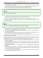
Component Specifications
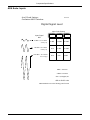
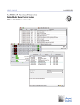
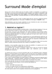
ADA Scale: Inputs
A to D Scale Settings
CueStation INPUTS window
20050929
Digital Signal Level
Input Scale Setting
Input Signal
dBu
+6
+16
+26
+6 dBu = 1.55 Vrms
2.2 V p-p
0 dBfs
+16 dBu = 4.9 Vrms
6.9 V p-p
CLIP
0 dBfs
-10 dBfs
+26 dBu = 15.5 Vrms
21.9 V p-p
CLIP
CLIP
0 dBfs
-10 dBfs -20 dBfs
0dBu=.775Vrms
+4dBu=1.23Vrms
dBu = (20log)E1/E2
dBfs is dB full scale
IEEE Standard 754 32 bit floating point format
29
Component Specifications
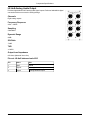
LX-Ao8 Analog Audio Output
Provides eight balanced-XLR analog audio signal outputs. Performs 24bit/48kHz digital
conversion with three conversion scaling settings.
Channels
Eight analog outputs.
Frequency Response
20Hz —20kHz.
Sampling
24bit/48kHz.
Dynamic Range
98dB.
S/N Ratio
-74dB.
THD
<0.005%
Output Load Impedance
600 ohms (balanced line-to-line)
Pin-out: LX-Ao8 balanced male XLR
Pin
Name
Use
1
GND
Shield
2
Signal+
+Analog balanced output
3
Signal-
-Analog balanced output
30
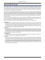
Component Specifications
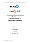
ADA Scale: Outputs
D to A Scale Setting
CueStation OUTPUTS window
20050929
Analog Output
Signal Level
Output Scale Setting
+6
+16
+26
Digital Signal Level
0 dBfs
+ 6 dBu
+16 dBu
+26 dBu
- 2 dBfs
+ 4 dBu
+14 dBu
+24 dBu
-10 dBu
- 0 dBu
+10 dBu
-16 dBfs
+6 dBu
1.55 Vrms
+16 dBu
4.9 Vrms
+26 dBu
15.5 Vrms
31
Component Specifications
LX-CBR CobraNet Audio Interface
Provides CobraNet 20bit/48kHz digital audio data transmission over Ethernet networks.
Pin-out
CobraNet communications: Use standard CAT5 cabling.
LED Status Indicator
Link
Watchdog
Conductor
Fault
RX Data
RX Error
TX Data
TX Error
Green LED indicates normal operation.
Red LED indicates a fault or error condition.
32
Component Specifications
LX-AES
33
Component Specifications
34
Component Specifications
LX-DSP System Processor
Performs matrix mixing automation and control, using the TI-TMS320C6701 Digital Signal Processor.
This DSP card also holds 32MB SDRAM and 8MB Flash memory, allowing stand-alone operation once
programmed with an automation cue list. The DSP is also interfaced to four relay contact outputs, four
digital sensor inputs and two analogue sensor inputs for control and reading of external devices.
Channels
Maximum 160/512 audio I/O channels
Dynamic Range
192dB
Digital Logic Inputs
LX-DSP cards with serial numbers 0000–0688 require an external pull-up resistor to use the Digital Logic
Inputs. Connect a 1/4W 2K2 resistor between the Digital Logic Input terminal and the +5V reference
voltage. One resistor is required for each Digital Logic Input.
Special DSP ID Numbers
The ID switch on an LX-DSP module can be set to force the LX-300 to erase the flash memory. This is not required
in normal operation. See Special DSP ID Codes (p. 16) for more information.
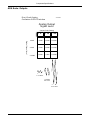
LX-DSP Pin-outs: LX-DSP Sensor I/O Terminal Block
Pin
Name
Signal
Use
1
+5V ref
+5V
Reference voltage
2
ADC1
0-5V
Analog sensor input
3
ADC2
0-5V
Analog sensor input
4
D1
5
D2
-TTL (active low with internal Digital logic input
2K2 pull-up resistor)
6
D3
7
D4
8
GND ref
GND
Reference ground
9
R1
500mA@48V max
Relay N/O dry contact
10
11
R2
12
13
R3
14
15
R4
16
35
Component Specifications
LX-EXP Expansion DSP
The expansion DSP card provides additional processing power for the LX-300.
LX-VRA VRAS DSP
The VRAS DSP provides reverberation, and early and late reflections capabilities for the Matrix3.
36
Component Specifications
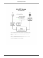
LX-ELC Ethernet/Wild Tracks
Provides Ethernet communications link between external hardware and the Matrix3 system. Also provides
a SCSI hard drive interface for use with Wild Tracks playback.
Ethernet connection is IEEE 802.3 and is 100 base T. Wiring must conform to EIA.TIA 568 standard with
CAT-5 or better cable.
Each LX-ELC module that is used for Wild Tracks requires a network connection to transfer audio files.
Wild Tracks drives provided by Meyer Sound do not have internal termination. An external terminator
must be used. LVD Ultra 160 active termination is provided.
Do not connect more than one LX-ELC to a SCSI bus. The LX-ELC is a SCSI controller and uses SCSI
ID 7. There can be only one controller on a SCSI bus.
Pin-out
Ethernet: Use standard CAT5 cabling.
SCSI disk connection: Ultra-SCSI. Use standard SCSI cabling. The connector is an Ultra2/SCSI VHDCI.
37
Component Specifications
LX-LNK Interconnect
Provides a high-speed connection between LX-300s. Carries command data and 32bit/48kHz digital audio
data. An optional optical transceiver module extends the maximum transmission range.
Use only Link cables from Meyer Sound. These are Fibre Channel cables that have been qualified for
high speed data use. They have a yellow label at each end that is marked "LX-Link".
Systems must be connected in a ring. The Next output of the LX-LNK module is connected to the Previous
input of the following LX-300.
Connections must be made in order of Frame ID. Frame 1 NEXT connects to Frame 2 PREVIOUS. Frame
2 NEXT connects to Frame 3 PREVIOUS, and so on.
The last LX-300 in a system must loop back to the first LX-300. Connect the NEXT output on the last LX300 to Frame ID 01 PREVIOUS input.
The Frame Status window on the front of the LX-300 will show green lights for Next and Previous when
the cables are properly connected to a LX-300.
Transmission Range
Up to 30m (100 feet) using copper cable.
Up to 500m (1000 feet) using multimode fiber optic cable and the optional fiber optic driver module.
Pin-outs
The link cable is a standard Fibre Channel™ cable. These have precision matched conductors. Please do not try
to build these without the required tooling and test equipment.
38
Component Specifications
39
Component Specifications
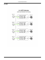
LX-COS Comm/Sync
Provides a communications link to the CueStation host computer system (or the computer
hosting your custom control software), a SMPTE Time Code signal generator and receiver,
and MIDI I/O.
Ports
RS232 serial, RS422 serial, MIDI In/Out, XLR SMPTE In/Out
Pin-outs
Table 4. Nine-pin Male RS232 Serial Port (DTE)
Pin
Name
Use
1
2
RX
Receive data
3
TX
Transmit data
4
5
GND
Reference ground
6
7
RTS
Ready to send (not required)
8
CTS
Clear to send (not required)
9
Table 5. Nine-pin Female RS422 Serial Port (DTE)
Pin
Name
Use
1
2
RX
Receive data
3
TX
Transmit data
4
5
GND
Reference ground
6
7
RTS
Ready to send (not required)
8
CTS
Clear to send (not required)
9
Table 6. Five-pin DIN Female MIDI In
Pin
Name
Use
1
2
3
4
RD+
Receive data
5
RD-
Receive data
40
Component Specifications
Table 7. Five-pin DIN Female MIDI Out
Pin
Name
Use
1
2
GND
Shield
3
4
+5V
Reference current
5
Data
Send data
Table 8. XLR Female SMPTE In
Pin
Name
Use
1
GND
Shield
2
+data
+Balanced analog input
3
-data
-Balanced analog input
Table 9. XLR Male SMPTE Out
Pin
Name
Use
1
GND
Shield
2
+data
+Balanced analog output
3
-data
-Balanced analog output
41
42
LX-300 Error Codes
Status LED Blink Codes
Frame Status Error Codes
Frame Status Error Messages
CueStation Log Window Messages
43
43
44
45
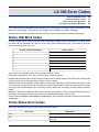
The LX-300 reports the identifiable errors through one or a combination of methods: Status LED blinking, Frame
Status error code reports, Frame Status error messages, and CueStation Log window messages.
Identifying the error and its probable root cause helps you choose an appropriate troubleshooting strategy.
Status LED Blink Codes
There are several system failure errors that make it impossible to display an error code directly. For these errors,
the Status LED will repeatedly blink the error code, with a pause between each cycle. The number of green-red
blinks corresponds to the error code.
Number of Green-Red Blinks
Cause of Error
1
Bad HSB File
2
Bad Serial File
3
Memory Allocation Error
4
File Size Mismatch
5
Bitfile Bad Program
6
Main FPGA Error
7
ISR Initialization Failure
These seven errors indicate a failure of the LX-DSP processor module.
Rebooting may resolve the error. The LX-300 should be treated as suspect.
Repeated failure indicates the LX-DSP processor module is non-functional. Replace the LX-DSP with a known-good
module. Return the non-working module to Meyer Sound for repairs.
Multiple LX-DSP failures indicate a problem with the LX-300 itself. Replace the LX-300 with a known-good LX-300.
You may re-use the modules from the non-working LX-300, but they should be treated as suspect until proved good
(they may have been damaged by the non-working LX-300.) Return the non-working LX-300 to Meyer Sound for
repairs.
Multiple LX-300 failures indicate a problem with the facility power system. This is a situation beyond the scope of
this manual. Facility power problems may result in non-warrantable damage to your LX-300s.
Please consult the Removal and Installation of Modules (p. 20) instructions for details on safe LX-300 expansion
dis/assembly.
Frame Status Error Codes
Most errors are shown as an error code on the Frame Status display.
Error Code
Explanation
IE12
Could not update Link FPGA program
IE13
Successfully returned from Flash program loading initmain.cpp
43
Frame Status Error Messages
Error Code
Explanation
IE14
Could not load Flash program
IE16
Could not start BoxNet
IE17
Could not start SerialNet
IE18
Could not obtain TCP/IP Hostname
IE19
Could not obtain Midi serial socket
IE20
Could not start Midi Parser
IE21
Could not start Midi Subsystem Manager
IE22
Could not start Subsystem
IE23
Could not start Midi Xfer system
IE24
Could not start CASL subsystem
IE25
Could not start Externals subsystem
IE26
Could not erase System Flash
IE27
Could not erase User Flash
IE28
Could not autostart Cue List
IE29
Could not start RIF subsystem
IE30
Could not start CobraNet subsystem
IE31
Could not start DSP subsystem
IE32
Could not start Relay subsystem
IE33
Could not erase EtherTracks Flash
IE34
Could not start TCP/IP subsystem
IE35
Could not start SMPTE subsystem
IE36
Could not start CueStation 4 server
These errors are self-explanatory, and indicate a problem with the system software.
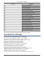
Frame Status Error Messages
Some errors are shown as a text message on the Frame Status display.
DMA0 DID NOT INTIALIZE PROPERLY. POWER CYCLE TO CORRECT
DMA1 DID NOT INTIALIZE PROPERLY. POWER CYCLE TO CORRECT
COBRANET DSP HAS STOPPED RESPONDING. POWER CYCLE TO CORRECT
MISSING BOOT ETHERTRACKS FILE. PLEASE SEND FILE
ETHERTRACKS FLASH FAILURE. REFLASH TO CORRECT
ETHERTRACKS DUALPORT FAILURE. POWER CYCLE TO CORRECT
ETHERTRACKS BOOT FAILURE. POWER CYCLE TO CORRECT
MISSING MAIN ETHERTRACKS FILE. PLEASE SEND FILE
ETHERTRACKS STARTUP FAILURE. POWER CYCLE TO CORRECT
CONFIGURATION FOR ETHERTRACKS MISSING. PLEASE SEND CONFIGURATION
COBRANET COMMUNICATION FAILURE. POWER CYCLE TO CORRECT
COBRANET INTERNAL FAILURE. POWER CYCLE TO CORRECT
These errors are non-fatal, but do require a firmware upload or that the LX-300 be rebooted.
44
CueStation Log Window Messages
Repeated occurrence of an error indicates a fault with the associated expansion module ("DMA0" corresponds to
an Analog Audio Input module; "DMA1" to a CobraNet module).
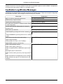
CueStation Log Window Messages
CueStation's Log window reports a number of errors from the Matrix3 system. These can be helpful in diagnosing
the root cause of a failure. The messages relevant to booting an LX-300 are:
Error Code
Explanation
M3 E1.5.0, Built on yy/mm/dd, at hh:mm:ss
No Flash program detected.
DMEM memory usage exceeded.
Total Dynamix points exceeded x
Matrix exceeds DSP capacity.
DSP Usage has reached limit. Halting processing. Please ADSIR_InterruptsHaveBackedUp
re-send configuration.
Corrupt audio detected. Muting audio for 1 second.
ADSIR_BadSampleDetected
Unmuting audio.
HSB Packet error detected
INITMAIN_HSB_Packet_Error
FLASH ReadFile got wrong CRC for file x, wanted y, got Flash program memory error
z
FLASH ReadRawFile got wrong CRC for file x, wanted y, got z
FPGA still not done after 4mSeconds waiting
Various FPGA programming errors
FPGA Length Mis-Match
FPGA program error. Byte x, bit x TotalBits x
FPGA 'DONE' not active at end of write.
ETRX: Cannot allocate memory
Various EtherTracks Errors
ETRX: Cannot read et_boot.bin (x)
ETRX: Corrupted DualPort->HSB transfer. [0x]=0x, should be 0x
Read Again: [0x]=0x, should be 0x
ETRX: Could not read et_linux.bin (x, 0x) Trying a second time
ETRX: CRC failed. ET=0x Should be=0x. #P=x LAST[0x] ETRX: # Packets not right. ET=0x Should be=0x. #P=x LAST[0x]
45
46
Appendix
Returns Policy
Shipping Address
47
47
Returns Policy
Please contact one of our product specialists:
Tel: +1 (626) 836-0446
Fax: +1 (626) 836-4883
http://LCSforums.com
[email protected]
Shipping Address
Product returns *must* be packaged appropriately. Shipment without adequate shock protection and electrostatic
discharge protection may void your product warranty. Level Control Systems can not assume responsibility for
damage caused during shipping.
When possible, return product using the original packaging.
ATTN: Repair Services
Meyer Sound Canada
100 Kal Lake Rd Suite 23
Vernon, BC, CANADA
V1T 9G1
47
48