1
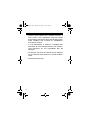
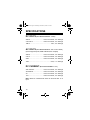
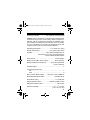
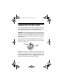
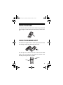
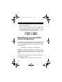
22-801.fm Page 1 Thursday, December 2, 1999 9:44 AM
Cat. No. 22-801
OWNER’S MANUAL
Please read before using this equipment.
35-Range Auto-Ranging
Digital Multimeter
22-801.fm Page 2 Thursday, December 2, 1999 9:44 AM
FEATURES
Your RadioShack 35-Range Auto-Ranging Digital Multimeter is
a portable, compact multimeter that is ideal for field, lab, shop,
bench, and home applications. The meter measures DC and
AC current up to 10 A, voltage up to 1000V DC and 750V AC,
resistance up to 40 MΩ, and capacitance from 4 nF–40 µF. Its
33/4-digit digital display means it can display up to 3,999 units.
Important:
• Completely read this manual before you use the meter.
• If you are not familiar with multimeters and testing procedures, we suggest you read the book Using Your Meter
(RadioShack Cat. No. 62-2039, not supplied) before you
use this meter.
Here are some features that make your new multimeter a real
pro:
Auto-Ranging with Manual-Ranging Override — automatically selects a range when you measure voltage, resistance,
capacitance, or current. You can also manually set the range
when measuring values you know are within a certain range.
Data Hold Function — the meter holds the displayed value, so
you can see the reading even after you disconnect the probes.
High-Speed Sampling — ensures quick, reliable measurements.
© 1999 Tandy Corporation.
All Rights Reserved.
RadioShack is a registered trademark used by Tandy Corporation.
2
22-801.fm Page 3 Thursday, December 2, 1999 9:44 AM
Auto Power Off — the meter helps conserve battery power by
sounding a beep then turning off if you do not change any settings for 5 minutes.
UL Listed — your meter has passed the stringent safety tests
required by Underwriters Laboratories.
Note: The UL mark does not indicate that this product has been
evaluated by Underwriters Laboratories for the accuracy of its
readings.
Latest IC and Display Technology — ensure reliability, accuracy, stability, and ease of operation.
Zero Function — lets you set the display to zero or to a reference point you select, then measure voltage, current, resistance, or capacitance around that reference.
Overload and Transient Protection — helps protect the meter
from overvoltage in most ranges.
Continuity Buzzer Function — lets you quickly hear if there is
continuity in a cable or between two points.
Diode Check Function — lets you safely check semiconductors for open, shorted, or normal junctions.
Auto-Polarity Operation — protects your meter and gives valid measurements even when you connect the leads in reverse
polarity.
3
22-801.fm Page 4 Thursday, December 2, 1999 9:44 AM
Low-Battery Indicator — so you can quickly see when you
need to replace the batteries.
Protective Rubber Boot — protects the meter from damage
and lets you hang the meter on a wall.
Note: Your multimeter requires one 9V battery (not supplied).
4
22-801.fm Page 5 Thursday, December 2, 1999 9:44 AM
CONTENTS
A Word About Safety ............................................................ 6
Special Panel Markings ........................................................ 9
Specifications ..................................................................... 10
Preparation ..........................................................................
Installing a Battery .........................................................
Connecting the Test Leads ............................................
Using the Stand .............................................................
Using the Rubber Boot ..................................................
15
15
18
19
19
About Ranging .................................................................... 20
Using the Meter ...................................................................
Manually Setting the Range ..........................................
Holding a Measurement ................................................
Zeroing the Meter/Using Relative Measurement ...........
Automatic/Manual Power Off .........................................
Disabling Automatic Power Off ...............................
21
24
24
25
28
28
Making Measurements .......................................................
Measuring DC/AC Voltage .............................................
Measuring AC Voltage Riding on a DC Source Bias .....
Measuring Three-Phase AC Voltage ......................
Measuring Current .........................................................
Measuring Resistance ...................................................
Measuring Capacitance .................................................
Checking Continuity .......................................................
Checking Diodes ...........................................................
Checking Diode Polarity .........................................
29
29
30
32
33
35
37
38
39
40
Care and Maintenance ........................................................ 41
Cleaning ........................................................................ 42
Replacing the Fuse ........................................................ 42
5
22-801.fm Page 6 Thursday, December 2, 1999 9:44 AM
A WORD ABOUT SAFETY
We have taken every precaution in designing this meter to ensure that it is as safe as we can make it. But safe operation depends on you, the operator. We recommend that you follow
these simple safety rules:
• Never apply voltages to the meter that exceed the limits
given in the specifications. Never apply more than 1000V
DC or 750V RMS AC between the input jacks and ground.
• Use extreme caution when working with voltages above
100V. Always disconnect power from the circuit you are
measuring before you connect test leads to high-voltage
points.
• Never connect the test leads to a source of voltage when
you select the diode check, resistance measurement,
capacitance measurement, or continuity functions, or any
of the current measurement functions.
• Always discharge any capacitors of the circuit under test
before you attach test leads.
• Always turn off power and disconnect the test leads from
the circuit you are testing before you replace the meter’s
batteries or fuse.
• Never operate the meter unless its back cover is in place
and fully closed.
• This equipment is rated for installation category II (maximum 3600 VA).
• Because many AC/DC sets have a potentially hot chassis,
be sure the top of your workbench and the floor underneath
it are made of non-conductive materials.
6
22-801.fm Page 7 Thursday, December 2, 1999 9:44 AM
This meter is fully calibrated and tested. Under normal use, no
further adjustment should be necessary except as noted in this
Owner’s Manual. If the meter requires repair, do not try to adjust
it yourself. Take it to your local RadioShack store.
WARNINGS:
• USE EXTREME CAUTION IN THE USE OF THIS DEVICE. IMPROPER USE OF THIS DEVICE CAN RESULT
IN INJURY OR DEATH. FOLLOW ALL SAFEGUARDS
SUGGESTED IN THIS OWNER’S MANUAL IN ADDITION
TO NORMAL SAFETY PRECAUTIONS IN DEALING
WITH ELECTRICAL CIRCUITS. DO NOT USE THIS
DEVICE IF YOU ARE UNFAMILIAR WITH ELECTRICAL
CIRCUITS AND TESTING PROCEDURES.
• NEVER TRY TO PROBE WITH BOTH TEST LEADS AT
THE SAME TIME OR HOLD BOTH TEST LEADS IN ONE
HAND.
• USE EXTREME CARE WHILE USING THE METER TO
MEASURE CURRENT AND VOLTAGE IN COMMERCIAL
ELECTRICAL PANELS. UNLIKE A HOME AC OUTLET, A
COMMERCIAL ELECTRICAL PANEL HAS TREMENDOUS CURRENT SURGE POTENTIAL. THIS IS ESPECIALLY TRUE FOR THREE-PHASE INDUSTRIAL
ELECTRICAL PANELS. A SMALL SPARK FROM ONE OF
THESE PANELS CAN CAUSE A PLASMA EXPLOSION
AND FIRE THAT CAN SEVERELY BURN YOU. DO NOT
HOLD THE METER WHILE USING IT.
7
22-801.fm Page 8 Thursday, December 2, 1999 9:44 AM
• ALWAYS WEAR PROTECTIVE LEATHER GLOVES, A
FACE SHIELD, AND FIREPROOF ARM AND UPPER
BODY PROTECTION WHILE USING THE METER TO MEASURE CURRENT AND VOLTAGE IN COMMERCIAL
ELECTRICAL PANELS.
• IF THIS EQUIPMENT IS USED IN A MANNER NOT
SPECIFIED BY THE MANUFACTURER, THE PROTECTION PROVIDED BY THE EQUIPMENT MAY BE
IMPAIRED.
• TO REDUCE THE RISK OF FIRE OR SHOCK HAZARD,
DO NOT EXPOSE THIS PRODUCT TO RAIN OR MOISTURE.
• FOR INDOOR USE ONLY.
8
22-801.fm Page 9 Thursday, December 2, 1999 9:44 AM
SPECIAL PANEL MARKINGS
For your safety, we have added special markings to the meter’s
panel to remind you of the measurement limitations.
10 A MAX
UNFUSED
The maximum current that you can measure
at this terminal is 10 amps.
Caution: This terminal is not fuse-protected.
500V
MAX
To avoid electrical shock or instrument damage, do not connect the common input terminal (–COM jack) to any source that exceeds
500 volts with respect to earth/ground.
!
Caution: Risk of electric shock! Refer to the
complete operating instructions.
1000V
750V
The maximum voltage that this meter can
measure is 1000V DC or 750V AC.
MAX
Caution: Be extra careful when making highvoltage measurements; DO NOT TOUCH
TERMINALS OR PROBE ENDS.
The meter is protected by double insulation.
CAT II
This equipment is rated for installation category II (max. 3600 VA).
9
22-801.fm Page 10 Thursday, December 2, 1999 9:44 AM
SPECIFICATIONS
DC VOLTS (MAX MEASUREMENT: 1000V)
400 mV ................................. ±2.5% of full scale, ±2 in last digit
4–40–400 V .......................... ±2.0% of full scale, ±2 in last digit
1000 V ...................................................... ±20 V, ±2 in last digit
AC VOLTS (MAX MEASUREMENT: 750 V at 50–100Hz)
(AC Average Response, RMS Calibrated, DC Coupled)
400 mV ................................. ±3.5% of full scale, ±3 in last digit
4–40 V .................................. ±3.0% of full scale, ±3 in last digit
400 V .................................... ±3.0% of full scale, ±3 in last digit
750 V ....................................................... ±30 V, ± 3 in last digit
DC CURRENT (MAX MEASUREMENT: 10 A)
400 µA/40 mA ...................... ±2.5% of full scale, ±2 in last digit
4mA/400 mA ......................... ±2.0% of full scale, ±2 in last digit
4A ......................................... ±2.5% of full scale, ±5 in last digit
10 A ...................................... ±2.0% of full scale, ±5 in last digit
Note: Based on measurement within 30 seconds after 10 A
input.
10
22-801.fm Page 11 Thursday, December 2, 1999 9:44 AM
AC CURRENT (MAX MEASUREMENT: 10A AT 60 HZ)
(AVERAGE RESPONSE, RMS CALIBRATED, DC COUPLED)
400 µA/40mA ....................... ±3.5% of full scale, ±3 in last digit
4 mA/400mA ........................ ±3.0% of full scale, ±3 in last digit
4A ........................................ ±3.5% of full scale, ±3 in last digit
10 A ..................................... ±3.0% of full scale, ±3 in last digit
Note: Based on measurement within 30 seconds after 10A
input.
RESISTANCE
400 Ω/4/40/400 KΩ .............. ±2.0% of full scale, ±3 in last digit
4 MΩ .................................... ±3.5% of full scale, ±3 in last digit
40 MΩ .................................. ±4.0% of full scale, ±3 in last digit
CAPACITANCE
4/40/400nF/4µF ................... ±3.0% of full scale, ±3 in last digit
40µF .................................... ±4.0% of full scale, ±3 in last digit
11
22-801.fm Page 12 Thursday, December 2, 1999 9:44 AM
CONTINUITY TEST
Open Circuit Voltage ...........................................2.5 V (Typical)
Short Circuit Current ................................................... < 2.0 mA
DIODE TEST
The diode test measures the voltage drop across the diode
under test.
Nominal Current ............................................. 1.0 mA @ 0.60 V
1.1 mA @ 0.0 V (short)
0.0 mA @ 2.5 V (open)
Overrange .......................... > 2.0 V DC to Vcc (2.5 V (Typical))
MISCELLANEOUS
Display ............................................... LCD 33/4-digit maximum,
4000 counts full scale
Range Selection ...................... Auto or manual range selection
Polarity .......................................... Automatic polarity selection
Input Impedance:
10 MΩ in parallel with <50 pF at DC/ACV function
Low Battery Indicator ........ BATT appears when battery voltage
drops below operating voltage of 6.4 V ± 0.3 V
12
22-801.fm Page 13 Thursday, December 2, 1999 9:44 AM
Overrange Indication .............. O.F (overflow) or OL (overload)
Caution: When O.F appears, it indicates that the measurement
exceeds the range for the current setting. When OL appears, it
indicates that the measurement exceeds the absolute maximum reading. Exceeding the maximum limits of the DC 1000V,
AC 750 V, and DC/AC 10 A ranges can damage the meter and
cause the meter to not show an overrange indication.
Operating Temperature ........................ 41 to 104°F (5 to 40°C)
Storage Temperature ....................... –4 to 140°F (–20 to 60°C)
Humidity .................................... Max. relative humidity 80% for
temperature up to 31°C, decreasing linearity
to 50% relative humidity at 40°C
Power Source ................................................... One 9V battery
Battery Life (at 5 Min. Use Per Day) ................ About 100 days
Battery Measurement Frequency .......... Every time operational
mode is changed
Pollution Degree ..................................................................... 2
Conversions Per Second:
Min. .................................................................................. 2
Max. ................................................................................. 9
Max. Common Mode Voltage ...... 500 V DC or 500 V RMS AC
Normal Mode Rejection Ratio ........................ > 60 dB at 60 Hz
Sleep Mode Timing ............................................ 5 ±1.5 Minutes
Range Up Detect Value .................... Overflow (>3999 Counts)
Range Down Detect Value ...................................... 380 Counts
Dimensions (HWD) ................................. 7 × 31/7 × 17/10 Inches
(178 × 80 × 43 mm)
13
22-801.fm Page 14 Thursday, December 2, 1999 9:44 AM
Weight (without batteries) .................... Approx. 10.6 oz (300 g)
Included Accessories ................................................ Test leads
Extra 500 mA 250V Ceramic Fuse
(such as Littelfuse® 216.500)
Specifications are typical; individual units might vary. Specifications are subject to change and improvement without notice.
14
22-801.fm Page 15 Thursday, December 2, 1999 9:44 AM
PREPARATION
INSTALLING A BATTERY
Your meter requires one 9 volt rectangular battery for power.
For the best performance and longest life, we recommend a RadioShack alkaline battery.
Warnings:
• To avoid electrical shock, disconnect both of the meter’s
test leads from any equipment before you install or remove
the meter’s battery.
• Do not operate your meter until the battery is properly
installed and the back cover is in place and secured.
Cautions:
• Use only a fresh battery of the required size and recommended type.
• Do not press RANGE, SELECT, or HOLD/ZERO while installing a battery.
• While the back cover is removed, do not touch any of the
components inside the meter other than as noted in this
Owner’s Manual. Doing so might damage the meter or
change its calibration.
Note: If the rubber boot has been attached to the meter, remove it before continuing (see “Using the Rubber Boot” on
Page 19).
15
22-801.fm Page 16 Thursday, December 2, 1999 9:44 AM
Rubber Boot
1. Turn off the meter if it is not already off (see “Automatic/
Manual Power Off” on Page 28), then disconnect the test
leads if they are connected.
2. Lift the stand on the back of the meter, then use a Phillips
screwdriver to loosen the screw in the meter’s back cover
and lift off the cover.
Stand
Screwdriver
3. Snap one terminal of a fresh 9 volt battery onto one of the
terminals in the battery compartment, then snap the other
battery terminal onto the other battery compartment terminal.
Caution: Connecting the battery to both of the battery terminals at the same time might cause the meter to lock up.
16
22-801.fm Page 17 Thursday, December 2, 1999 9:44 AM
Note: If the meter automatically turns on, continue with
Step 4. If the meter does not automatically turn on, press
SELECT. If the meter still does not turn on, press RESET on
the circuit board. The meter turns on.
RESET
4. Replace the cover and secure it with the screw.
When BATT appears on the right side of the display, replace the
battery.
Warning: Dispose of old batteries promptly and properly.
Cautions:
• Always remove an old or weak battery. Batteries can leak
chemicals that can destroy electronic parts.
• If you are not going to use the meter for a few weeks,
remove the battery.
17
22-801.fm Page 18 Thursday, December 2, 1999 9:44 AM
CONNECTING THE TEST LEADS
The test leads supplied with your meter are rated for 1000 volts.
Use only test leads of the same rating with the meter. You can
order replacement leads from your local RadioShack store.
WARNING: ALTHOUGH THE TEST LEADS ARE RATED FOR
1000 VOLTS, THE MAXIMUM RATING OF THIS METER IS
1000 VOLTS DC/750 VOLTS RMS AC. DO NOT TRY TO MEASURE ANY VOLTAGE GREATER THAN 1000 VOLTS DC/750
VOLTS RMS AC.
Plug the black test lead’s right-angled end into the meter’s –
COM (common) jack, then plug the red test lead’s right-angled
end into the +V.mA.Ω jack.
Black
Red
Caution: If the current in the circuit you are measuring is in the
10A DC/AC range or you do not know the amount of current in
the circuit (see “Measuring Current” on Page 33), plug the red
test lead’s right-angled end into the 10A MAX jack instead of the
+V.mA.Ω jack, to help prevent damage to the meter.
18
22-801.fm Page 19 Thursday, December 2, 1999 9:44 AM
USING THE STAND
The fold-out stand on the back of the meter lets you place the
meter upright on a flat surface (as shown here) for easier viewing.
USING THE RUBBER BOOT
The rubber boot supplied with the meter helps protect the meter
from damage. Simply slide the meter into the boot.
Use the clips on the back of the boot to store the test leads
while you are not using them. The keyhole on the back of the
boot lets you hang the meter on a wall.
Keyhole
Clips
19
22-801.fm Page 20 Thursday, December 2, 1999 9:44 AM
ABOUT RANGING
Your meter sets itself to its automatic ranging mode each time
you turn it on. In this mode, the meter automatically selects the
next higher or lower range (if available) when the measurement
causes the display to overflow (the meter tries to display 4000
or more units) or underflow (the meter tries to display 380 or
fewer units).
If a voltage or current measurement exceeds 4000 units, the
meter might display O.F (overflow) then automatically select
the next higher range (if available). For example, 3.200 appears when the meter measures a 3.2 V DC voltage. Then, if
the voltage is increased to 4.1 volts, the meter might display
O.F then change the range to the 40-volt range. (The tables on
Pages 22 and 23 show what the meter displays when set to its
different ranges).
If a voltage or current measurement falls below 380 units, the
meter might display UF (underflow) then automatically select
the next lower range (if available). For example, 4.50 appears
when the meter measures a 4.5 V DC voltage. Then if the voltage is decreased to 3.799 volts, the meter might display UF
then change the range to the next lower range.
Notes:
• You can also manually set the meter’s range (see “Manually Setting the Range” on Page 24).
• Since the meter switches ranges quickly, you might not
actually see O.F or UF on the display.
20
22-801.fm Page 21 Thursday, December 2, 1999 9:44 AM
USING THE METER
For the most accurate readings, the temperature should be between 65°F and 83°F (18°C and 28°C), with a maximum of 80%
relative humidity.
Before you use your meter for the first time, follow these steps
to familiarize yourself with its operation.
Warning: Always turn off power to the circuit you are about to
measure before you probe the test leads into high-voltage
points.
Caution: Be sure to select the correct function before you touch
the test leads to the circuit or component to be tested.
1. Press ON/SELECT to turn on the meter if it is not already on.
HEllO flashes and:
• if the selector is set to V
, 0.4/4 mA, 40/400 mA, or 4/
10A, the meter sets itself to its DC/auto test mode
Ω, O.F appears
• if the selector is set to
• if the selector is set to
2. Set the selector to V
, OPEn appears
.
21
22-801.fm Page 22 Thursday, December 2, 1999 9:44 AM
3. Repeatedly press RANGE to set the meter to manual ranging so you can view the different measurement ranges.
AUTO disappears and the decimal point shifts each time
you press RANGE. See “Manually Setting the Range” on
Page 24.
4. Turn the selector to change between the meter’s functions
and familiarize yourself with the displays.
Your meter automatically sets itself to the range that gives
the best reading. The unit of measure that appears on the
display shows you the range that the meter is currently set
to. For example, mV appears in the 400 mV range and V
appears in the 400 V range. Also, note the position of the
decimal. For example, if.000 V appears, the meter is set to
measure less than 4 volts. If 0000 V appears, the meter is
set to measure up to 1000 volts.
Read the range in volts, ohms, or amps as indicated by the
position of the decimal point.
Range
22
Display
400 mV
ddd.d
mV
4V
d.ddd
V
40 V
dd.dd
V
400 V
ddd.d
V
1000V DC
dddd
V
750V RMS AC
ddd
V
40 mA
dd.dd
mA
22-801.fm Page 23 Thursday, December 2, 1999 9:44 AM
Range
Display
400 mA
ddd.d
mA
400 ohms
ddd.d
Ω
4 KΩ
d.ddd
KΩ
40 KΩ
dd.dd
KΩ
400 KΩ
ddd.d
KΩ
4 MΩ
d.ddd
MΩ
4V (Fixed Range)
d.ddd
V
Note: The display might show a phantom reading in some
DC and AC voltage ranges when the test leads are not
connected to a circuit. This is normal. The high input sensitivity produces a “wandering” effect. When you connect the
test leads to a circuit, a real measurement appears.
5. Connect the test leads to the circuit you want to measure.
To measure different circuits, see “Making Measurements”
on Page 29.
Cautions:
• If O.F (overflow) appears, the value you are measuring
exceeds the range for the setting you selected. This is normal when you measure resistance or a diode, or do not
have the leads connected to a component. If you are measuring voltage or current when O.F appears, however,
immediately disconnect the probes from the circuit.
23
22-801.fm Page 24 Thursday, December 2, 1999 9:44 AM
• If OL (overload) appears, the value you are measuring
exceeds the meter’s maximum range. Immediately disconnect the probes from the circuit.
MANUALLY SETTING THE RANGE
When you measure voltages, resistance, or capacitance, your
meter is preset to automatically select a measuring range.
When you measure current, the meter is preset to automatically
select a range within the limits of the selector’s setting. While
this feature is convenient, it might be faster to manually set the
range when measuring values that you know are within a certain range.
To switch to manual range control, press RANGE. AUTO disappears and the meter holds the range at its current setting. To
change the range, repeatedly press RANGE.
To reselect automatic range control, press SELECT. AUTO appears and the meter automatically selects the range that gives
the best reading.
HOLDING A MEASUREMENT
Press HOLD/ZERO to hold all indications on the display. DH (display hold) appears and the meter holds the measured value on
the display even if you remove the probes from the circuit.
24
22-801.fm Page 25 Thursday, December 2, 1999 9:44 AM
Note: You cannot change the selected range while the meter is
holding a measurement.
To cancel hold, press HOLD/ZERO again or set the selector to
another setting. DH disappears.
ZEROING THE METER/USING
RELATIVE MEASUREMENT
You can set the meter to have it not show an unwanted value
that might appear as a result of internal or other factors, called
zeroing. For example, the meter always shows a small value
Ω to measure capacitance,
when you set the selector to
even when you have not connected the test leads to a component. (This happens because the meter measures its own internal capacitance, which is normal). If you zero the meter, it does
not display this value when you measure a component.
You can also set the meter to a baseline reference value called
relative measurement. For example, if you are measuring resistors with a 100 ohm rating and you want to see the resistor’s tolerance (the actual value in ohms above or below the resistor’s
rating), you can set the meter to a baseline reference value of
100 ohms so it displays only the resistor’s tolerance.
25
22-801.fm Page 26 Thursday, December 2, 1999 9:44 AM
Caution: Your meter has a circuit to protect the resistance
range from over-voltage. However, to prevent accidentally exceeding the protection circuit’s rating and to ensure a correct
measurement, never connect the test leads to a source of voltΩ, 0.4/4 mA, 40/400 mA, or
age while the selector is set to
4/10A. This could damage the meter or the circuit being tested.
Note: To use the zero feature in higher ranges, manually select
the range before you short the leads together.
Follow these steps to zero the meter or use relative measurement.
1. Set the selector to any setting except
.
2. Touch the test leads together (if you are zeroing the meter)
or connect the test leads to the component whose measurement you want to use as a reference value (if you are
using relative measurement).
Note: Do not short the test leads together in Steps 2 and 3
if you are measuring capacitance.
3. While touching the test leads together or while the test
leads are connected to a component, hold down HOLD/
ZERO until DH appears and the value on the display stops
changing. Then hold down SELECT until REL appears and
AUTO and DH disappear.
The meter automatically subtracts the value on the display
from the next measurement you make.
4. Use the meter to make a measurement.
26
22-801.fm Page 27 Thursday, December 2, 1999 9:44 AM
Notes:
• If the reference value you measured in Step 2 is greater
than the value of the measurement you made in Step 4, the
meter shows a negative value. This is not a malfunction.
• You must zero the meter or set a new reference value each
time you change the range or mode.
• The meter automatically sets itself to manual ranging when
you use this function.
• O.F appears as usual if you measure values outside of the
meter’s currently set range.
• You cannot zero the meter to an out-of-range value.
• If you are using the meter to take a relative measurement,
repeat Steps 2–3 to set the reference value to the current
input value.
• The meter displays values greater than 4000 counts as
long as the range used is not an overflow range. (A count is
the smallest unit of measure that the meter can measure).
For example, if you store –3.5 volts as a reference, then
measure +3.5 volts, the meter might display 7.0 volts.
To reset zeroing or a relative measurement, press SELECT or
RANGE to change the current range or set the selector to another setting.
27
22-801.fm Page 28 Thursday, December 2, 1999 9:44 AM
AUTOMATIC/MANUAL POWER OFF
Your meter conserves power by automatically turning off about 5 minutes after the
last time you changed settings (even if you
are making measurements). OFF appears
and the meter beeps as it turns itself off.
To turn the meter back on after it automatically turns off, press
any button (SELECT, RANGE, or HOLD/ZERO).
To manually turn off the meter before it turns itself off, make
sure the selector is not set to
, then press HOLD/ZERO. DH
appears. Then hold down RANGE until OFF appears. When you
release RANGE, the meter beeps then turns off.
Disabling Automatic Power Off
To set the meter so it does not turn off automatically, make sure
the meter is turned off. Then hold down RANGE and SELECT at
the same time until the meter turns on and PLOc (power-lock)
appears.
To turn off the meter and reset it so it automatically turns off the
next time you turn it on, follow these steps.
1. Press HOLD/ZERO. DH appears.
2. Hold down RANGE until OFF appears, then release RANGE.
The meter beeps then turns off.
3. Press any key to turn on the meter.
28
22-801.fm Page 29 Thursday, December 2, 1999 9:44 AM
MAKING MEASUREMENTS
MEASURING DC/AC VOLTAGE
Warnings:
• Never clamp a test lead to a hot wire (usually red, black, or
blue in AC wiring circuits). If one lead is clamped to a hot
wire and you touch the meter’s other probe, you could
receive an electric shock.
• The maximum input limit for voltage measurement is 1000V
DC or 750V AC (RMS). To avoid electrical shock and damage to the meter, never try to measure a DC voltage above
1000 volts or an AC voltage above 750 volts RMS.
Follow these steps to measure AC or DC voltage.
1. Set the selector to V
.
2. Hold down SELECT to set the meter to measure AC voltage
(
appears on the left side of the display) or DC voltage
(
disappears).
3. Touch the test leads to the circuit you want to test. If the
meter is set to automatic range control, the meter automatically moves to the range that gives the best reading.
If you set the meter to use manual range control (see Step
3 under “Using the Meter” on Page 21), repeatedly press
RANGE to change the range (if necessary).
When you measure AC voltages,
appears on the left side of the display
and V or mV appear on the right side.
29
22-801.fm Page 30 Thursday, December 2, 1999 9:44 AM
When you measure DC voltages,
the left side of the display.
does not appear on
Note: In the 400 V and 400 mV ranges, the decimal point
appears in the same position (one place to the left). To distinguish between the two ranges, mV appears in the 400
mV range, and V appears in the 400 V range.
MEASURING AC VOLTAGE RIDING
ON A DC SOURCE BIAS
To measure AC voltage superimposed on a DC voltage source
bias while ignoring the DC voltage, you must first measure the
AC and DC voltages separately, then compute the peak voltage
using this formula:
Peak voltage = DC voltage + AC voltage/0.707
Warning: To avoid injury or damage to your meter, never try to
measure an AC voltage that is riding on a DC source bias
where the peak AC voltage exceeds 750V with respect to earth
ground.
Follow these steps to measure an AC voltage superimposed on
a DC voltage source bias.
1. Press SELECT to turn on the meter if it is not already on.
30
22-801.fm Page 31 Thursday, December 2, 1999 9:44 AM
2. Set the selector to V
.
3. Hold down SELECT to set the meter to measure DC voltage
(
disappears).
4. Touch the test leads to the circuit you want to test and note
the reading. The display shows the DC voltage.
5. Disconnect the test leads from the circuit.
6. Remove power from the circuit under test and discharge all
capacitors.
7. Hold down SELECT to set the meter to measure AC voltage
(
appears).
8. Connect a 0.1 microfarad/1000V capacitor in series with
the positive terminal of the voltage source and the red test
lead.
9. Connect the black test lead to ground, then connect power
to the circuit you want to measure and note the reading.
The display shows the AC voltage.
Warning: To avoid electric shock, never touch the circuit
and test terminals while testing.
10. When you finish measuring the AC voltage, disconnect the
power from the circuit under test then disconnect the
capacitor you connected in Step 8.
31
22-801.fm Page 32 Thursday, December 2, 1999 9:44 AM
Measuring Three-Phase AC Voltage
We designed this meter primarily to measure household AC
voltages. If you want to measure 3-phase, line-to-line voltages,
please note the following:
• Because of the dangers inherent in measuring three-phase
circuits, we strongly recommend you do not use this meter
for such applications.
• The actual voltage can be greater than the circuit’s rated
line-to-ground voltage.
Most 3-phase power circuits are rated by their line-to-line voltage. This voltage is higher than the line (or phase) to ground
voltage. To determine if a line-to-line 3-phase voltage exceeds
the rating of this meter, multiply the rated line-to-ground voltage
by 1.732 (the square root of 3). For example, if the rated line-toground voltage is 640 volts, the line-to-line voltage is 640 ×
1.732 = 1108 V AC.
Warning: This voltage exceeds the meter’s rating. Therefore,
you should not connect the meter to this circuit or to any equipment connected to the circuit. Doing so could present a dangerous shock hazard to you, and could also damage the meter.
32
22-801.fm Page 33 Thursday, December 2, 1999 9:44 AM
MEASURING CURRENT
To measure AC or DC current, you must break the circuit and
connect the test leads to two circuit connection points. The connection must be in series with the circuit under test.
Warning: The meter’s internal components might become dangerously hot if you measure current in the 10 A DC/AC range.
Make measurements within 30 seconds after you connect the
meter to the circuit and allow the meter to cool for 15 minutes
between measurements.
Cautions:
• Never connect the test leads across a voltage source.
Doing so can damage the meter or the circuit under test.
The maximum input limit for AC/DC current measurement
is 10 A.
• If you do not know the amount of current in the circuit you
are measuring, always set the selector to 4/10 A and connect the red test lead to the 10A MAX jack.
1. Set the selector to 0.4/4 mA, 40/400 mA, or 4/10A.
2. Hold down SELECT to set the meter to measure AC current
(
appears) or DC current (
disappears).
3. Remove power from the circuit under test and discharge all
capacitors.
4. Plug the black test lead into the –COM jack and the red test
lead into the appropriate jack.
33
22-801.fm Page 34 Thursday, December 2, 1999 9:44 AM
5. Connect the meter’s test leads in series with the circuit.
6. Apply power and read the current.
7. If the measurement is less than 400 mA, the red test lead is
connected to 10A MAX, and the selector is set to 4/10A:
• a. Remove power from the circuit
• b. Move the red test lead to the +V.mA.Ω jack
• c. Set the selector to 40/400 mA
• d. Reapply power to the circuit.
Otherwise, if the measurement is less than 4 mA, the red
test lead is connected to the +V.mA.Ω jack, and the selector
is set to 40/400 mA:
• a. Remove power from the circuit
• b. Set the selector to 0.4/4 mA
• c. Reapply power to the circuit.
If the measured current’s polarity is negative,
before the value.
appears
Notes:
• If your measurement exceeds the currently selected range,
O.F appears until the measured voltage or current is reduced to a value below the currently selected range. If your
measurement exceeds the absolute maximum reading and
the selector is set to 4/10A, OL appears until the measured
voltage or current is reduced to a value below the absolute
maximum reading.
34
22-801.fm Page 35 Thursday, December 2, 1999 9:44 AM
• The 0.4/4 mA and 40/400 mA ranges are fuse-protected. If
the meter does not show a reading in these ranges, check
the fuse (see “Replacing the Fuse” on Page 42).
MEASURING RESISTANCE
The resistance measuring circuit in your meter compares the
voltage gained through a known resistance (internal) with the
voltage developed across an unknown resistance.
Warning: Be sure the circuit under test has all power removed
and any associated capacitors are fully discharged before you
make a resistance measurement.
Caution: Your meter has a circuit to protect the resistance
range from over-voltage. However, to prevent accidentally exceeding the protection circuit’s rating and to ensure a correct
measurement, never connect the test leads to a source of voltΩ.
age while the selector is set to
Follow these steps to measure resistance.
1. Remove all power from the circuit under test and discharge
all capacitors.
2. Set the selector to
Ω.
Caution: Never connect the test leads to a source of voltΩ.
age while the selector is set to
3. Hold down SELECT to set the meter to measure resistance.
Ω, K Ω, or M Ω appears.
35
22-801.fm Page 36 Thursday, December 2, 1999 9:44 AM
Note: With no resistance connected across the test leads
(meaning resistance is infinite), O.F appears when you set
the meter to measure resistance. This is normal.
4. Touch the test leads across the circuit you want to measure, or remove one of the leads of the component you
want to measure from its circuit and touch the test leads
across the component. If the meter is set to automatic
range control, it automatically moves to the proper range.
If you selected manual range control, repeatedly press
RANGE to change the range (if necessary).
Notes:
• If you are measuring resistance of about 1 MΩ or more,
the display might take a few seconds to stabilize. This is
normal.
• As with the voltage range, use the measuring units that
appear on the display to determine the current resistance range. If only Ω appears, the values of the measurements are in ohms. If K and Ω appear, the meter is
measuring kilohms (1 kilohm = 1000 Ω). If M and Ω
appear, the meter is measuring megohms (1 megohm =
1,000,000 Ω).
Hint: If you want to accurately measure a very small resistance,
you can view the resistance of the meter’s test leads and fuse,
then subtract that resistance from the measured value. To measure the meter’s internal resistance, simply touch the ends of
the test leads together. The meter selects the 400 Ω scale and
displays its internal resistance. You can also use the meter’s
zero feature to do this (see “Zeroing the Meter/Using Relative
Measurement” on Page 25).
36
22-801.fm Page 37 Thursday, December 2, 1999 9:44 AM
MEASURING CAPACITANCE
The capacitance measuring circuit in your meter charges a connected capacitor to a specific voltage level, then discharges the
capacitor to a lower voltage. The meter measures the amount of
time it takes to discharge the capacitor.
1. Remove all power from the circuit under test and discharge
all capacitors.
2. Set the selector to
Ω.
3. Hold down SELECT to set the meter to measure capacitance. nF or µF (a capacitance range) appears on the right
side of the display.
4. Attach the red test lead to the positive side of the capacitor
and attach the black test lead to the negative side of the
capacitor. Or, remove one of the leads of the capacitor you
want to measure from its circuit and connect the test leads
to the capacitor.
Note: Electrolytic capacitors have positive and negative
terminals. Be sure to connect each test lead to the correct
terminal to match the polarity of these capacitors.
5. Read the measured value on the display.
Notes:
• The voltage applied across electrolytic capacitors will affect
their measured values. That is, a measurement taken with
a low voltage will be different and lower than that taken with
a voltage that approaches the capacitor’s voltage rating.
37
22-801.fm Page 38 Thursday, December 2, 1999 9:44 AM
Since this meter cannot use high voltage to set the electrolyte, it cannot measure the absolute value of capacitance.
• Low value capacitors might match or be close to the actual
input capacitance of your meter. To measure low capacitance values, use the meter’s zero feature to adjust the
meter for the meter’s own capacitance (see “Zeroing the
Meter/Using Relative Measurement” on Page 25).
• The accuracy of capacitance measurement depends on
the measurement method and also differs with different
types of capacitors. The readings as shown on the meter’s
display are consistent to ±3% percent and ±3 digits. However, the meter’s measurement is for reference only.
CHECKING CONTINUITY
You can use the meter to check for shorted or open electrical
circuits.
1. Remove all power from the circuit under test and discharge
all capacitors.
2. Set the selector to
3. Hold down SELECT until
display.
.
appears on the left side of the
4. Touch the test leads across the circuit you want to measure. Shrt appears and the buzzer sounds if the circuit
resistance is less than about 50 ohms (meaning the circuit
is continuous or shorted). OPEn appears and the meter’s
buzzer does not sound if the circuit resistance is greater
than about 50 ohms (meaning the circuit is not continuous).
38
22-801.fm Page 39 Thursday, December 2, 1999 9:44 AM
CHECKING DIODES
This procedure lets you check diodes, transistors, and other
semiconductors for opens, shorts, and normal operation. It also
lets you determine the forward voltage and polarity for diodes.
(This is handy when you need to match a diode.) You can also
check LEDs using this procedure.
Caution: Do not connect the test leads to a source of voltage
with the selector set to
. This could damage the meter or
the circuit being tested.
1. Remove all power from the circuit under test and discharge
all capacitors.
2. Set the selector to
3. Hold down SELECT until
.
appears.
4. Connect the test leads to the device you want to check, or
remove one of the leads of the component you want to
measure from its circuit and connect the test leads to the
component.
5. Reverse the test leads and note the second reading.
If one reading shows a value and the other is overrange
(O.F appears) the device is good. If O.F appears during
both readings, the device is open. If both values are very
small or zero, the device is shorted.
39
22-801.fm Page 40 Thursday, December 2, 1999 9:44 AM
Notes:
• When you test a silicon-type semiconductor, the values
might vary depending on the temperature.
• The values that appear during a diode check show the
actual forward voltage (max. 2.0V). If the voltage exceeds
2.0V, O.F appears. This means the diode check cannot be
made using this meter.
Checking Diode Polarity
Many diodes have a stripe or mark on one side. The marked
side of the diode indicates the diode’s cathode or negative (–)
side. The other side is the anode or positive (+) side.
Cathode
Diode
Anode
+
If a diode is not marked, you can use your meter to check the diode’s polarity. As you follow the steps under “Checking Diodes”
on Page 39, connect the red test lead to one side, connect the
black test lead to the other side, then measure and note the
voltage. Then reverse the test leads and measure and note the
second reading. The side of the diode where the meter shows a
higher voltage using the red test lead is the anode (+) side.
40
22-801.fm Page 41 Thursday, December 2, 1999 9:44 AM
CARE AND MAINTENANCE
Your RadioShack 35-Range Auto-Ranging Digital Multimeter is
an example of superior design and craftsmanship. The following suggestions will help you care for your meter so it will serve
you for years.
Keep the meter dry. If it gets wet, wipe it dry immediately. Liquids might contain minerals that can corrode the electronic circuits.
Use and store the meter only in normal temperature environments. Temperature extremes can
shorten the life of electronic devices, damage batteries, and distort or melt plastic parts.
Keep the meter away from dust and dirt, which can
cause premature wear of parts.
Handle the meter gently and carefully. Dropping it
can damage circuit boards and cases and can
cause the meter to work improperly.
Use only a fresh battery of the required size and
recommended type. Batteries can leak chemicals
that damage your meter’s electronic parts.
Wipe the meter with a damp cloth occasionally to
keep it looking new. Do not use harsh chemicals,
cleaning solvents, or strong detergents to clean the
meter.
41
22-801.fm Page 42 Thursday, December 2, 1999 9:44 AM
Modifying or tampering with the meter’s internal components
can cause a malfunction and might invalidate its warranty. If
your meter is not performing as it should, take it to your local
RadioShack store for assistance.
CLEANING
To keep the meter looking new, occasionally wipe it with a cloth
slightly dampened with water. Do not use harsh chemicals,
cleaning solvents, or strong detergents to clean the meter.
Warnings:
• Do not let any water drip inside the meter while cleaning it.
• Make sure that the meter is completely dry before using it.
REPLACING THE FUSE
If the meter does not work, you might need to replace the fuse
with the spare fuse we have included with your meter. The
spare fuse is next to the battery compartment.
42
22-801.fm Page 43 Thursday, December 2, 1999 9:44 AM
The fuse is a 500 mA, 250V ceramic fuse (such as Littelfuse®
216.500).
Caution: Do not use a fuse with ratings other than those specified here. Doing so might damage your meter.
Follow these steps to replace the fuse.
1. Turn the meter off if it is not already off (see “Automatic/
Manual Power Off” on Page 28), then disconnect the test
leads if they are connected.
Warning: To avoid electric shock, you must disconnect the
test leads before you remove the back cover.
2. Lift the stand on the back of the meter. Then use a Phillips
screwdriver to loosen the screw in the back cover and lift
off the cover.
Screwdriver
3. To remove the fuse, gently pull the red ribbon holding it.
The fuse pops out.
Fuse
43
22-801.fm Page 44 Thursday, December 2, 1999 9:44 AM
4. If the fuse is blown, discard it and save the ribbon (to use
with the next spare fuse you store in the compartment).
Then remove the spare fuse and the ribbon holding it from
beside the battery compartment and insert it into the fuse
holder.
5. Replace the back cover and secure it with the screw.
Warning: Do not operate your meter until the back cover is in
place and secured.
44
22-801.fm Page 45 Thursday, December 2, 1999 9:44 AM
NOTES
45
22-801.fm Page 46 Thursday, December 2, 1999 9:44 AM
46
22-801.fm Page 47 Thursday, December 2, 1999 9:44 AM
47
22-801.fm Page 48 Thursday, December 2, 1999 9:44 AM
Limited Ninety-Day Warranty
This product is warranted by RadioShack against manufacturing defects in material
and workmanship under normal use for ninety (90) days from the date of purchase
from RadioShack company-owned stores and authorized RadioShack franchisees
and dealers. EXCEPT AS PROVIDED HEREIN, RadioShack MAKES NO EXPRESS WARRANTIES AND ANY IMPLIED WARRANTIES, INCLUDING THOSE
OF MERCHANTABILITY AND FITNESS FOR A PARTICULAR PURPOSE, ARE
LIMITED IN DURATION TO THE DURATION OF THE WRITTEN LIMITED WARRANTIES CONTAINED HEREIN. EXCEPT AS PROVIDED HEREIN, RadioShack
SHALL HAVE NO LIABILITY OR RESPONSIBILITY TO CUSTOMER OR ANY
OTHER PERSON OR ENTITY WITH RESPECT TO ANY LIABILITY, LOSS OR
DAMAGE CAUSED DIRECTLY OR INDIRECTLY BY USE OR PERFORMANCE OF
THE PRODUCT OR ARISING OUT OF ANY BREACH OF THIS WARRANTY, INCLUDING, BUT NOT LIMITED TO, ANY DAMAGES RESULTING FROM INCONVENIENCE, LOSS OF TIME, DATA, PROPERTY, REVENUE, OR PROFIT OR ANY
INDIRECT, SPECIAL, INCIDENTAL, OR CONSEQUENTIAL DAMAGES, EVEN IF
RadioShack HAS BEEN ADVISED OF THE POSSIBILITY OF SUCH DAMAGES.
Some states do not allow the limitations on how long an implied warranty lasts or the
exclusion of incidental or consequential damages, so the above limitations or exclusions may not apply to you.
In the event of a product defect during the warranty period, take the product and the
RadioShack sales receipt as proof of purchase date to any RadioShack store. RadioShack will, at its option, unless otherwise provided by law: (a) correct the defect
by product repair without charge for parts and labor; (b) replace the product with one
of the same or similar design; or (c) refund the purchase price. All replaced parts and
products, and products on which a refund is made, become the property of RadioShack. New or reconditioned parts and products may be used in the performance
of warranty service. Repaired or replaced parts and products are warranted for the
remainder of the original warranty period. You will be charged for repair or replacement of the product made after the expiration of the warranty period.
This warranty does not cover: (a) damage or failure caused by or attributable to acts
of God, abuse, accident, misuse, improper or abnormal usage, failure to follow instructions, improper installation or maintenance, alteration, lightning or other incidence of excess voltage or current; (b) any repairs other than those provided by a
RadioShack Authorized Service Facility; (c) consumables such as fuses or batteries;
(d) cosmetic damage; (e) transportation, shipping or insurance costs; or (f) costs of
product removal, installation, set-up service adjustment or reinstallation.
This warranty gives you specific legal rights, and you may also have other rights
which vary from state to state.
RadioShack Customer Relations, 200 Taylor Street, 6th Floor, Fort Worth, TX 76102
We Service What We Sell
12A99
04/99
811082200A
Printed in China