1
Commissioning and Fault Finding
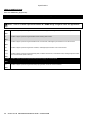
9 FAULT FINDING
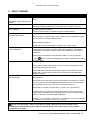
SYMPTOM
Unit is inoperative
Read/Write configuration does not
operate
Unit shuts down
Continuous starting of generator
when in AUTO
Generators fail to start on receipt
of Remote Start signal.
POSSIBLE REMEDY
Check the battery and wiring to the unit. Check the DC supply. Check the DC
fuse.
Check DC supply voltage is not above 35 Volts or below 9 Volts
Check the operating temperature is not above 70°C. Check the DC fuse.
Check that there is no signal present on the “Remote Start” input. Check
configured polarity is correct.
Check the mains supply is available and within configured limits.
Check Start Delay timer has timed out.
Check signal is on “Remote Start” input. Confirm correct configuration of input
is configured to be used as “Remote Start”.
Check MSC link operation
Module appears to ‘revert’ to an
earlier configuration
Check 8660 ATS and 8610 engine controllers are in AUTO mode.
When editing a configuration using the PC software it is vital that the
configuration is first ‘read’ from the controller before editing it. This edited
configuration must then be “written” back to the controller for the changes to
take effect.
When editing a configuration using the fascia editor, be sure to press the
Bus will not take load
Accept
button to save the change before moving to another item or exiting
the fascia editor
Ensure the generator available LED is lit
Check that the output configuration is correct to drive the load switch device
and that all connections are correct.
Inaccurate measurements on
controller display
Remember that the set will not take load in manual mode unless the mains
supply fails, a remote start on load input is present or the close generator
button is pressed.
Check that the CT primary, CT secondary and VT ratio settings are correct for
the application.
Check that the CTs are wired correctly with regards to the direction of current
flow (p1,p2 and s1,s2) and additionally ensure that CTs are connected to the
correct phase (errors will occur if CT1 is connected to phase 2).
Remember to consider the power factor. Ie (kW = kVA x powerfactor)
The 8600 series controller is true RMS measuring so gives more accurate
display when compared with an ‘averaging’ meter such as an analogue panel
meter or some lower specified digital multimeters.
Accuracy of the controller is better than 1% of full scale. Ie Gen volts full scale
is 333V ph-n so accuracy is ±3.33V (1% of 333V).
NOTE:- The above fault finding is provided as a guide check-list only. As the module can be
configured to provide a wide range of different features, always refer to the source of your module
configuration if in doubt.
Part No. 057-120 8660 OPERATING MANUAL ISSUE 1 07/05/2010 ADM
69