1
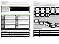
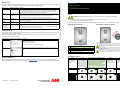
PVS300 user interface Navigation map Control the inverter from either the front panel or, if applicable, a control unit situated in a remote location. The layout of the user interface is similar in both cases. After the inverter is turned on, it initializes and enters normal operation. Graphical display Use the graphical display to see the operational status, user-navigable menus, performance monitoring, event messages (for example, faults, warnings, maintenance reminders) and help. Common display zones 1 4 3 2 1 Status bar: Includes the view title, date and status icon. 2 Content area: Different for each view. It displays the actual subject matter of the current view. For example, a menu, parameter or help page. 3 Current output power: Shows “-- kW” if disconnected from the grid and “0 kW” if connected to the grid but not power feeding. 4 Cumulative electricity produced: In kilowatt hours for the displayed time period so far. 5 Softkey bar: Shows the softkey labels and the real time clock. The labels change from view to view. 5 You will normally see the Output view which shows the status and history of power produced by the system. You can cycle through these views in an endless loop. In most screens you can use the left softkey to toggle between a graphical and numerical representation of the data. The Output views show the amount of energy produced during the respective time period. You can select the format of graphs from the Date and time menu. The current column of histogram displays is shown in a different color to the others. Note: In multi-unit installations, the output values can be applied to show the whole system instead of individual inverters (Screen Menu). Control buttons and LED status indicator The control buttons are used to navigate the menus. Not all buttons can be used in all views. Control Usage Control Usage Use the up and down buttons to scroll up and down to different items within menu screens and to adjust values. Briefly push the button to select the next row in the menu. Hold the button to quickly scroll through the possible choices. Use the left and right buttons to navigate to the previous (higher level) and next (lower level) menu screens respectively. Also use them to move the cursor horizontally during parameter editing. Use the left softkey to select items shown on the bottom left of the display. Usually use this to step backwards. If held, the left softkey exits each menu and nested view in turn, finally returning to the Output View. When the display shows the Output View, use this button to toggle between numeric and graphical displays. Use the right softkey to select items shown on the bottom right of the display. Use this key to affirm, acknowledge and confirm, for example to select yes, OK, proceed. Use the ? (help) button to access the available contextsensitive problem-solving instructions and descriptions of functions and parameters. The LED status indicator shows the current operating status of the inverter. The LED changes color and flashes, depending on the status. The Total page shows cumulative values since the unit was installed. CO2 reduction is shown only if a reduction factor is selected to be larger than 0. The sun display appears automatically if the control buttons are not touched for a while. When the inverter is producing power, the rays are filled in proportion to the current power output. Access Menu at any time to adjust settings and parameters. Views in the Menu hierarchy Editing parameters using the control buttons To edit a parameter, select the parameter name from the menu. Use the arrow keys to select or adjust each parameter, and the right softkey to save or confirm the selection. When setting parameters, pushing the up and down arrows together will restore the selected parameter to the default value. Status LED indications View Description Date & time Use this to set the time, date and display format. Select daylight saving adjustments from this menu. Language Use this to set the language of the user interface. CO2 reduction Use this to select the CO2 reduction factor for the installation. Control unit bi-color LED Status Description Screen Use this to set the screen brightness, contrast, backlight and screensaver delay. OFF Going to sleep The inverter sleeps when there is not enough light to operate. Events ON Red Fault There is an active fault which needs user action to reconnect to the grid. Consists of two menus: faults and other events. This view shows the date and nature of the fault or event. Push the Help (?) button to see any available information about the event. Flashing Red (1s ON, 2s OFF) Warning There is an active warning and the inverter is temporarily in stand-by mode. Communication Flashing Green (1s ON, 2s OFF) Stand-by The inverter is in stand-by mode with no faults present. Use this to set up communications for remote monitoring, 3-phase system configurations and external control systems via programmable output relay. Flashing Green (3s ON, 1s OFF) Limited operation The inverter is operating with limited output power. ON Green Normal operation The inverter is in normal power feeding mode. System info System information includes viewing a subset of parameter groups that tell the product type and software version. Self test Use this to activate the self test (an automated test for testing the protection functions of the inverter).