1
BreezeNET® B130/B300 GigE
Technical User Manual
Software Version: 1.3
July 2010
P/N 215745
Document History
Document History
Changed Item
Description
Date
First revision
Document’s first revision
April 2009
Section 2.2
Added BNB 130
November 2009
Third revision
Added GigE functionality
July 2010
Alvarion BreezeNET B130/B300 GigE
ii
Technical User Manual
Legal Rights
Legal Rights
© Copyright 2010 Alvarion Ltd. All rights reserved.
The material contained herein is proprietary, privileged, and confidential and
owned by Alvarion or its third party licensors. No disclosure thereof shall be made
to third parties without the express written permission of Alvarion Ltd.
Alvarion Ltd. reserves the right to alter the equipment specifications and
descriptions in this publication without prior notice. No part of this publication
shall be deemed to be part of any contract or warranty unless specifically
incorporated by reference into such contract or warranty.
Trade Names
Alvarion®, BreezeCOM®, WALKair®, WALKnet®, BreezeNET®, BreezeACCESS®,
BreezeLINK® and/or other products and/or services referenced here in are either
registered trademarks, trademarks or service marks of Alvarion Ltd.
All other names are or may be the trademarks of their respective owners.
Statement of Conditions
The information contained in this manual is subject to change without notice.
Alvarion Ltd. shall not be liable for errors contained herein or for incidental or
consequential damages in connection with the furnishing, performance, or use of
this manual or equipment supplied with it.
Warranties and Disclaimers
All Alvarion Ltd. ("Alvarion") products purchased from Alvarion or through any of
Alvarion's authorized resellers are subject to the following warranty and product
liability terms and conditions.
Exclusive Warranty
(a) Alvarion warrants that the Product hardware it supplies and the tangible
media on which any software is installed, under normal use and conditions, will
be free from significant defects in materials and workmanship for a period of
fourteen (14) months from the date of shipment of a given Product to Purchaser
(the "Warranty Period"). Alvarion will, at its sole option and as Purchaser's sole
remedy, repair or replace any defective Product in accordance with Alvarion'
standard R&R procedure.
(b) With respect to the Firmware, Alvarion warrants the correct functionality
according to the attached documentation, for a period of fourteen (14) month from
invoice date (the "Warranty Period")". During the Warranty Period, Alvarion may
release to its Customers firmware updates, which include additional performance
Alvarion BreezeNET B130/B300 GigE
iii
Technical User Manual
Legal Rights
improvements and/or bug fixes, upon availability (the "Warranty"). Bug fixes,
temporary patches and/or workarounds may be supplied as Firmware updates.
Additional hardware, if required, to install or use Firmware updates must be
purchased by the Customer. Alvarion will be obligated to support solely the two (2)
most recent Software major releases.
ALVARION SHALL NOT BE LIABLE UNDER THIS WARRANTY IF ITS TESTING
AND EXAMINATION DISCLOSE THAT THE ALLEGED DEFECT IN THE PRODUCT
DOES NOT EXIST OR WAS CAUSED BY PURCHASER'S OR ANY THIRD
PERSON'S MISUSE, NEGLIGENCE, IMPROPER INSTALLATION OR IMPROPER
TESTING, UNAUTHORIZED ATTEMPTS TO REPAIR, OR ANY OTHER CAUSE
BEYOND THE RANGE OF THE INTENDED USE, OR BY ACCIDENT, FIRE,
LIGHTNING OR OTHER HAZARD.
Disclaimer
(a) The Software is sold on an "AS IS" basis. Alvarion, its affiliates or its licensors
MAKE NO WARRANTIES, WHATSOEVER, WHETHER EXPRESS OR IMPLIED,
WITH RESPECT TO THE SOFTWARE AND THE ACCOMPANYING
DOCUMENTATION. ALVARION SPECIFICALLY DISCLAIMS ALL IMPLIED
WARRANTIES OF MERCHANTABILITY AND FITNESS FOR A PARTICULAR
PURPOSE AND NON-INFRINGEMENT WITH RESPECT TO THE SOFTWARE.
UNITS OF PRODUCT (INCLUDING ALL THE SOFTWARE) DELIVERED TO
PURCHASER HEREUNDER ARE NOT FAULT-TOLERANT AND ARE NOT
DESIGNED, MANUFACTURED OR INTENDED FOR USE OR RESALE IN
APPLICATIONS WHERE THE FAILURE, MALFUNCTION OR INACCURACY OF
PRODUCTS CARRIES A RISK OF DEATH OR BODILY INJURY OR SEVERE
PHYSICAL OR ENVIRONMENTAL DAMAGE ("HIGH RISK ACTIVITIES"). HIGH
RISK ACTIVITIES MAY INCLUDE, BUT ARE NOT LIMITED TO, USE AS PART OF
ON-LINE CONTROL SYSTEMS IN HAZARDOUS ENVIRONMENTS REQUIRING
FAIL-SAFE PERFORMANCE, SUCH AS IN THE OPERATION OF NUCLEAR
FACILITIES, AIRCRAFT NAVIGATION OR COMMUNICATION SYSTEMS, AIR
TRAFFIC CONTROL, LIFE SUPPORT MACHINES, WEAPONS SYSTEMS OR
OTHER APPLICATIONS REPRESENTING A SIMILAR DEGREE OF POTENTIAL
HAZARD. ALVARION SPECIFICALLY DISCLAIMS ANY EXPRESS OR IMPLIED
WARRANTY OF FITNESS FOR HIGH RISK ACTIVITIES.
(b) PURCHASER'S SOLE REMEDY FOR BREACH OF THE EXPRESS
WARRANTIES ABOVE SHALL BE REPLACEMENT OR REFUND OF THE
PURCHASE PRICE AS SPECIFIED ABOVE, AT ALVARION'S OPTION. TO THE
FULLEST EXTENT ALLOWED BY LAW, THE WARRANTIES AND REMEDIES SET
FORTH IN THIS AGREEMENT ARE EXCLUSIVE AND IN LIEU OF ALL OTHER
WARRANTIES OR CONDITIONS, EXPRESS OR IMPLIED, EITHER IN FACT OR BY
OPERATION OF LAW, STATUTORY OR OTHERWISE, INCLUDING BUT NOT
Alvarion BreezeNET B130/B300 GigE
iv
Technical User Manual
Legal Rights
LIMITED TO WARRANTIES, TERMS OR CONDITIONS OF MERCHANTABILITY,
FITNESS FOR A PARTICULAR PURPOSE, SATISFACTORY QUALITY,
CORRESPONDENCE WITH DESCRIPTION, NON-INFRINGEMENT, AND
ACCURACY OF INFORMATION GENERATED. ALL OF WHICH ARE EXPRESSLY
DISCLAIMED. ALVARION' WARRANTIES HEREIN RUN ONLY TO PURCHASER,
AND ARE NOT EXTENDED TO ANY THIRD PARTIES. ALVARION NEITHER
ASSUMES NOR AUTHORIZES ANY OTHER PERSON TO ASSUME FOR IT ANY
OTHER LIABILITY IN CONNECTION WITH THE SALE, INSTALLATION,
MAINTENANCE OR USE OF ITS PRODUCTS.
Limitation of Liability
(a) ALVARION SHALL NOT BE LIABLE TO THE PURCHASER OR TO ANY THIRD
PARTY, FOR ANY LOSS OF PROFITS, LOSS OF USE, INTERRUPTION OF
BUSINESS OR FOR ANY INDIRECT, SPECIAL, INCIDENTAL, PUNITIVE OR
CONSEQUENTIAL DAMAGES OF ANY KIND, WHETHER ARISING UNDER
BREACH OF CONTRACT, TORT (INCLUDING NEGLIGENCE), STRICT LIABILITY
OR OTHERWISE AND WHETHER BASED ON THIS AGREEMENT OR
OTHERWISE, EVEN IF ADVISED OF THE POSSIBILITY OF SUCH DAMAGES.
(b) TO THE EXTENT PERMITTED BY APPLICABLE LAW, IN NO EVENT SHALL
THE LIABILITY FOR DAMAGES HEREUNDER OF ALVARION OR ITS EMPLOYEES
OR AGENTS EXCEED THE PURCHASE PRICE PAID FOR THE PRODUCT BY
PURCHASER, NOR SHALL THE AGGREGATE LIABILITY FOR DAMAGES TO ALL
PARTIES REGARDING ANY PRODUCT EXCEED THE PURCHASE PRICE PAID
FOR THAT PRODUCT BY THAT PARTY (EXCEPT IN THE CASE OF A BREACH OF
A PARTY'S CONFIDENTIALITY OBLIGATIONS).
Radio Frequency Interference Statement
The Slave equipment has been tested and found to comply with the limits for a
class B digital device, pursuant to ETSI EN 301 489-1 rules and Part 15 of the
FCC Rules. These limits are designed to provide reasonable protection against
harmful interference when the equipment is operated in a residential environment
notwithstanding use in commercial, business and industrial environments. This
equipment generates, uses, and can radiate radio frequency energy and, if not
installed and used in accordance with the instruction manual, may cause harmful
interference to radio communications.
The Master equipment has been tested and found to comply with the limits for a
class A digital device, pursuant to part 15 of the FCC rules and to EN 301 489-1
rules. These limits are designed to provide reasonable protection against harmful
interference when the equipment is operated in commercial, business and
industrial environments. This equipment generates, uses, and can radiate radio
frequency energy and, if not installed and used in accordance with the instruction
Alvarion BreezeNET B130/B300 GigE
v
Technical User Manual
Legal Rights
manual, may cause harmful interference to radio communications. Operation of
this equipment in a residential area is likely to cause harmful interference in
which case the user will be required to correct the interference at the user’s own
expense.
FCC Radiation Hazard Warning
To comply with FCC RF exposure requirement, the antenna used for this
equipment must be fixed-mounted on outdoor permanent structures with a
separation distance of at least 2 meters from al persons.
Antenna Compliance Statement
This device has been designed to operate with the antennas listed in Table 2-5,
and having a maximum gain of 28 dBi. Antennas not included in this list or
having a gain greater than 28 dBi are strictly prohibited for use with this device.
The required antenna impedance is 50 ohms.
To reduce potential radio interference to other users, the antenna type and its
gain should be so chosen that the Equivalent Isotropically Radiated Power (EIRP)
is not more than that permitted for successful communication.
R&TTE Compliance Statement
This equipment complies with the appropriate essential requirements of Article 3
of the R&TTE Directive 1999/5/EC.
Safety Considerations - General
For the following safety considerations, "Instrument" means the BreezeACCESS
units' components and their cables.
Safety Considerations - DC Powered Equipment
Restricted Access Area: The DC powered equipment should only be installed in a
Restricted Access Area.
Installation Codes: The equipment must be installed according to the latest
edition of the country national electrical codes. For North America, equipment
must be installed in accordance with the US National Electrical Code and the
Canadian Electrical Code.
The equipment must be connected directly to the DC Supply System
grounding electrode conductor.
All equipment in the immediate vicinity must be grounded in the same way,
and not be grounded elsewhere.
Alvarion BreezeNET B130/B300 GigE
vi
Technical User Manual
Legal Rights
The DC supply system is to be local, i.e. within the same premises as the
equipment.
There shall be no disconnect device between the grounded circuit conductor of
the DC source (return) and the point of connection of the grounding electrode
conductor.
Caution
To avoid electrical shock, do not perform any servicing unless you are qualified to
do so.
Line Voltage
Before connecting this instrument to the power line, make sure that the voltage of
the power source matches the requirements of the instrument.
Radio
The instrument transmits radio energy during normal operation. To avoid possible
harmful exposure to this energy, do not stand or work for extended periods of time
in front of its antenna. The long-term characteristics or the possible physiological
effects of radio frequency electromagnetic fields have not been yet fully
investigated.
Outdoor Units and Antennas Installation and Grounding
Ensure that outdoor units, antennas and supporting structures are properly
installed to eliminate any physical hazard to either people or property. Make sure
that the installation of the outdoor unit, antenna and cables is performed in
accordance with all relevant national and local building and safety codes. Even
where grounding is not mandatory according to applicable regulation and national
codes, it is highly recommended to ensure that the outdoor unit and the antenna
mast (when using external antenna) are grounded and suitable lightning
protection devices are used so as to provide protection against voltage surges and
static charges. In any event, AlvarionThe Supplier is not liable for any injury,
damage or regulation violations associated with or caused by installation,
grounding or lightning protection.
Disposal of Electronic and Electrical Waste
Disposal of Electronic and Electrical Waste
Pursuant to the WEEE EU Directive electronic and electrical waste must not be disposed of with
unsorted waste. Please contact your local recycling authority for disposal of this product.
Alvarion BreezeNET B130/B300 GigE
vii
Technical User Manual
Important Notice
Important Notice
This user manual is delivered subject to the following conditions and restrictions:
This manual contains proprietary information belonging to Alvarion Ltd. Such
information is supplied solely for the purpose of assisting properly authorized
users of the respective Alvarion products.
No part of its contents may be used for any other purpose, disclosed to any
person or firm or reproduced by any means, electronic and mechanical,
without the express prior written permission of Alvarion Ltd.
The text and graphics are for the purpose of illustration and reference only.
The specifications on which they are based are subject to change without
notice.
The software described in this document is furnished under a license. The
software may be used or copied only in accordance with the terms of that
license.
Information in this document is subject to change without notice. Corporate
and individual names and data used in examples herein are fictitious unless
otherwise noted.
Alvarion Ltd. reserves the right to alter the equipment specifications and
descriptions in this publication without prior notice. No part of this
publication shall be deemed to be part of any contract or warranty unless
specifically incorporated by reference into such contract or warranty.
The information contained herein is merely descriptive in nature, and does not
constitute an offer for the sale of the product described herein.
Any changes or modifications of equipment, including opening of the
equipment not expressly approved by Alvarion Ltd. will void equipment
warranty and any repair thereafter shall be charged for. It could also void the
user's authority to operate the equipment.
Alvarion BreezeNET B130/B300 GigE
viii
Technical User Manual
About this Manual
About this Manual
This User Manual is a description of Alvarion devices and contains installation
and configuration guidelines, recommendations and troubleshooting sections,
and supplementary materials. The document is intended to be used by Qualified
RF engineers/technicians and IT professionals. Qualified personnel should have
skills and experience in the following areas:
Outdoor/indoor radio equipment installation
Outdoor wireless networks
TCP/IP networking protocols
Safety procedures and instructions for installing antenna equipment
Professional manage of electrical equipment and accessories
Safety procedures and instructions for working on towers and heights
Alvarion BreezeNET B130/B300 GigE
ix
Technical User Manual
Contents
Contents
Chapter 1 - Getting Started ..................................................................... 1
1.1 Scope of Document....................................................................................................3
1.2 Abbreviations .............................................................................................................4
1.3 Document Marks ........................................................................................................5
Chapter 2 - Hardware Description .......................................................... 6
2.1 Power supply units (IDU)...........................................................................................8
2.1.1 IDU-BS-G ............................................................................................................8
2.2 Outdoor Units (ODU)................................................................................................10
2.2.1 BU/RB-B130D/B300D-5X-GigE ........................................................................10
2.2.2 BU/RB-B130/B300-5X-GigE .............................................................................11
2.2.3 ODU LED Indicators Description.......................................................................12
2.3 Installation Preparations .........................................................................................13
2.3.1 Required Components and Accessories...........................................................13
2.3.2 Antenna Placement...........................................................................................13
2.3.3 Antenna Poles Usage .......................................................................................14
2.3.4 Poles with Stretching.........................................................................................15
2.3.5 Wall Mounted Pole ............................................................................................15
2.3.6 Antenna Poles Requirements ...........................................................................15
2.3.7 Grounding when Using IDU-BS-G ....................................................................15
2.3.8 Antenna Alignment............................................................................................16
2.3.9 Precaution Measures ........................................................................................16
2.3.10 Service Cable Soldering Procedure ..................................................................17
2.3.11 Tools Required at the Installation Site ..............................................................20
2.4 BU/RB-B130D/B300D-5X-GigE ................................................................................22
2.4.1 Installation Guidelines .......................................................................................22
2.5 BU/RB-B130/B300-5X-GigE .....................................................................................25
2.5.1 Installation Guidelines .......................................................................................25
2.6 Mounting Kit (MOUNT-KIT-85).................................................................................27
Alvarion BreezeNET B130/B300 GigE
x
Technical User Manual
Contents
2.6.1 Assembly...........................................................................................................28
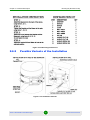
2.6.2 Possible Variants of the Installation ..................................................................29
2.7 Specifications ...........................................................................................................31
2.7.1 Radio.................................................................................................................31
2.7.2 Antenna.............................................................................................................33
2.7.3 Data Communication.........................................................................................33
2.7.4 Configuration Management...............................................................................33
2.7.5 Electrical Characteristics...................................................................................34
2.7.6 Physical and Environmental..............................................................................34
2.7.7 Standards and Regulations...............................................................................34
Chapter 3 - Basic Configuration Instructions ....................................... 35
3.1 Initial Settings Configuration Procedure ...............................................................37
3.2 Device Interfaces......................................................................................................39
3.3 Command Line Interface (CLI) ................................................................................40
3.4 Lost Password Recovery.........................................................................................41
3.5 Configuration Manipulations...................................................................................45
3.5.1 Printing and Saving Your Configuration ............................................................45
3.5.2 Import/Export.....................................................................................................45
3.5.3 IP Address Formats ..........................................................................................45
3.6 Ethernet Interface Configuration ............................................................................47
3.7 Radio Interface Configuration.................................................................................48
Chapter 4 - Link Configuration .............................................................. 50
4.1 Link Diagnostic Tools ..............................................................................................52
4.1.1 Ltest ..................................................................................................................52
4.1.2 Muffer ................................................................................................................55
4.1.3 Load Meter ........................................................................................................58
4.1.4 Acquiring Interfaces Statistics ...........................................................................59
4.1.5 RapidView .........................................................................................................60
Alvarion BreezeNET B130/B300 GigE
xi
Technical User Manual
Contents
Chapter 5 - Configuration Via Web Interface........................................ 66
5.1 Overall Functionality Overview...............................................................................68
5.2 Run Requirements ...................................................................................................69
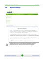
5.3 Basic Settings...........................................................................................................70
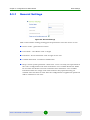
5.3.1 General Settings ...............................................................................................71
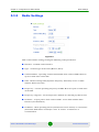
5.3.2 Radio Settings...................................................................................................72
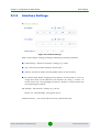
5.3.3 Interface Settings ..............................................................................................73
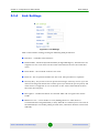
5.3.4 Link Settings......................................................................................................74
5.3.5 MAC Switch.......................................................................................................75
5.3.6 QoS Options......................................................................................................77
5.4 Device Status............................................................................................................78
5.4.1 Extended Link Diagnostic..................................................................................79
5.5 Maintenance..............................................................................................................88
5.6 Spectrum Analyzer...................................................................................................89
5.7 Command Line Emulation .......................................................................................92
Chapter 6 - Supplementary Information................................................ 93
6.1 "RJ-45" Service Cable Connector Soldering Scheme ..........................................95
6.2 Console Cable Connector Soldering Scheme .......................................................96
Alvarion BreezeNET B130/B300 GigE
xii
Technical User Manual
List of Tables
List of Tables
Table 2-1: Types of Units ............................................................................................................ 10
Table 2-2: ODU LED Indicators Description................................................................................ 12
Table 2-3: RJ-45 Connector Soldering Procedure ...................................................................... 18
Table 2-4: Radio Specifications................................................................................................... 31
Table 2-5: Antenna Specifications .............................................................................................. 33
Table 2-6: Data Communication Specifications .......................................................................... 33
Table 2-7: Configuration Management Specifications................................................................. 33
Table 2-8: Electrical Characteristics Specifications..................................................................... 34
Table 2-9: Physical and Environmental Specifications................................................................ 34
Table 2-10: Standards and Regulations Compliance.................................................................. 34
Table 4-1: Indicator LEDs ........................................................................................................... 64
Alvarion BreezeNET B130/B300 GigE
xiii
Technical User Manual
List of Figures
List of Figures
Figure 2-1: IDU-BS-G Top View.................................................................................................... 8
Figure 2-2: IDU-BS-G Front Panel ................................................................................................ 8
Figure 2-3: IDU-BS-G Rear Panel................................................................................................. 9
Figure 2-4: Connection scheme for IDU-BS-G.............................................................................. 9
Figure 2-5: BU/RB-B130D/B300D-5X-GigE Front Panel ............................................................ 10
Figure 2-6: BU/RB-B130D/B300D-5X-GigE Top View ................................................................ 11
Figure 2-7: BU/RB-B130/B300-5X-GigE Front Panel.................................................................. 11
Figure 2-8: BU/RB-B130/B300-5X-GigE Top View ..................................................................... 12
Figure 2-9: Grounding ................................................................................................................. 16
Figure 2-10: BU/RB-B130D/B300D-5X-GigE Installation 1......................................................... 22
Figure 2-11: BU/RB-B130D/B300D-5X-GigE Installation 2......................................................... 23
Figure 2-12: BU/RB-B130/B300-5X-GigE Installation 1 .............................................................. 25
Figure 2-13: BU/RB-B130/B300-5X-GigE Installation 2 .............................................................. 26
Figure 2-14: Mounting Kit ............................................................................................................ 28
Figure 2-15: Mounting Instructions.............................................................................................. 29
Figure 2-16: Installation Variants................................................................................................. 29
Figure 3-1: ERConsole (Step 1) .................................................................................................. 41
Figure 3-2: ERConsole (Step 2) .................................................................................................. 42
Figure 3-3: ERConsole (Step 3) .................................................................................................. 43
Figure 3-4: ERConsole (Step 4) .................................................................................................. 44
Figure 4-1: Ltest .......................................................................................................................... 52
Figure 4-2: Ltest Align ................................................................................................................. 54
Figure 4-3: Ltest Bandwidth Meter .............................................................................................. 54
Figure 4-4: Muffer Review Mode ................................................................................................. 55
Figure 4-5: Muffer MAC2 Mode................................................................................................... 56
Figure 4-6: Muffer Statistics Mode .............................................................................................. 57
Figure 4-7: Load Meter................................................................................................................ 59
Alvarion BreezeNET B130/B300 GigE
xiv
Technical User Manual
List of Figures
Figure 4-8: Netstat ...................................................................................................................... 60
Figure 4-9: RapidView Top.......................................................................................................... 61
Figure 4-10: RapidView Back...................................................................................................... 62
Figure 4-11: RapidView Indicator Panel...................................................................................... 62
Figure 5-1: Basic Settings ........................................................................................................... 70
Figure 5-2: General Settings ....................................................................................................... 71
Figure 5-3: .................................................................................................................................. 72
Figure 5-4: Interface Settings ...................................................................................................... 73
Figure 5-5: Link Settings ............................................................................................................. 74
Figure 5-6: MAC Switch .............................................................................................................. 75
Figure 5-7: Group Rules.............................................................................................................. 76
Figure 5-8: QoS Options ............................................................................................................. 77
Figure 5-9: Device Status............................................................................................................ 78
Figure 5-10: Extended Link Diagnostics...................................................................................... 80
Figure 5-11: Antenna Alignment ................................................................................................. 80
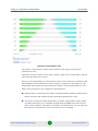
Figure 5-12: Antenna Alignment Graphical Indicator .................................................................. 82
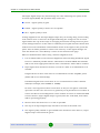
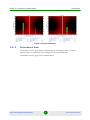
Figure 5-13: Good Link Sample .................................................................................................. 84
Figure 5-14: Bad Link Sample..................................................................................................... 85
Figure 5-15: Performance Test ................................................................................................... 86
Figure 5-16: Performance Test Sample ...................................................................................... 87
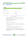
Figure 5-17: Maintenance ........................................................................................................... 88
Figure 5-18: Spectrum Analyzer.................................................................................................. 89
Figure 5-19: Command Line Emulator ........................................................................................ 92
Figure 6-1: Service Cable Connector Soldering Scheme............................................................ 95
Figure 6-2: Console Cable Connector Soldering Scheme .......................................................... 96
Alvarion BreezeNET B130/B300 GigE
xv
Technical User Manual
Chapter
1
Getting Started
Chapter 1 - Getting Started
In This Chapter:
“Scope of Document” on page 3
“Abbreviations” on page 4
“Document Marks” on page 5
Alvarion BreezeNET B130/B300 GigE
2
Technical User Manual
Chapter 1 - Getting Started
1.1
Scope of Document
Scope of Document
This document consists of the following chapters:
“Getting Started” on page 1 - This chapter includes the information about this
document purpose and structure.
“Hardware Description” on page 6 - This chapter shows the devices
appearance and all plugs and connectors.
“Basic Configuration Instructions” on page 35 - This chapter includes basic
recommendations for primary link configuration, including interfaces
configuration and MINT protocol usage. Also there is a description of how to
perform basic manipulations with device's configuration including its
updating, importing and exporting.
“Link Configuration” on page 50 - The chapter contains basic
recommendations for making preliminary choices and decisions while
planning and deploying a wireless network based on the Devices. It also
describes a set of tools that can help while improving the link quality and
statistics gathering.
“Configuration Via Web Interface” on page 66 - This chapter describes the
device's built-in services, features and tools which were not described in
previous parts of the document.
“Supplementary Information” on page 93 - Contains supplementary
information (specifications, connectors soldering scheme).
Alvarion BreezeNET B130/B300 GigE
3
Technical User Manual
Chapter 1 - Getting Started
1.2
Abbreviations
Abbreviations
The following abbreviations are used in this document:
ODU - Outdoor Unit
IDU - Indoor power supply Unit
RF cable - Radio Frequency cable to connect ODU and external antenna in
case connectorized version of the unit is used
LOS - Line-of-Sight
STP cable - Shielded Twisted Pair cable (STP Cat5E) to connect ODU and IDU
PTP - Point-to-Point topology
MINT - Microwave Interconnection NeTworks
Alvarion BreezeNET B130/B300 GigE
4
Technical User Manual
Chapter 1 - Getting Started
1.3
Document Marks
Document Marks
CAUTION
All caution warnings are marked with a special warning sign. One should pay a great deal of
attention to what is written in the Warning sections.
NOTE
All notes are marked with a special note sign. Notes usually contain useful comments or hints to the
described section of the document.
Alvarion BreezeNET B130/B300 GigE
5
Technical User Manual
Chapter
2
Hardware Description
Chapter 2 - Hardware Description
In This Chapter
“Power supply units (IDU)” on page 8
“Outdoor Units (ODU)” on page 10
“Installation Preparations” on page 13
“BU/RB-B130D/B300D-5X-GigE” on page 22
“BU/RB-B130/B300-5X-GigE” on page 25
“Mounting Kit (MOUNT-KIT-85)” on page 27
“Specifications” on page 31
Alvarion BreezeNET B130/B300 GigE
7
Technical User Manual
Chapter 2 - Hardware Description
Power supply units (IDU)
2.1
Power supply units (IDU)
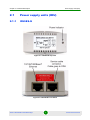
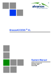
2.1.1
IDU-BS-G
Figure 2-1: IDU-BS-G Top View
Figure 2-2: IDU-BS-G Front Panel
Alvarion BreezeNET B130/B300 GigE
8
Technical User Manual
Chapter 2 - Hardware Description
Power supply units (IDU)
Figure 2-3: IDU-BS-G Rear Panel
Figure 2-4: Connection scheme for IDU-BS-G
Alvarion BreezeNET B130/B300 GigE
9
Technical User Manual
Chapter 2 - Hardware Description
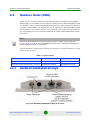
2.2
Outdoor Units (ODU)
Outdoor Units (ODU)
There are two versions of outdoor units (BreezeNET B130 GigE and BreezeNET
B300 GigE), each available in two hardware configurations. BreezeNET B130 GigE
is a limited version of the BreezeNET B300 GigE model, with a maximum bitrate of
130 Mbps. BreezeNET B130 GigE units can be upgraded to BreezeNET B300 GigE
by acquiring an appropriate license and by following the indications described in
the “Upgrading Procedure from BreezeNET B130 GigE to BreezeNET B300 GigE”
document.
NOTE
Although the BreezeNET B130’s maximum bitrate is limited to 130 Mbps, the Ltest utility (see
“Ltest” on page 52) is not. Thus, the full radio link capacity (of up to 250 Mbps net throughput) of
the BreezeNET B130 units may be sampled.
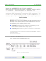
The two firmware configurations and the two hardware versions combine to a total
of four types of units:
Table 2-1: Types of Units
Hardware Configuration
300 Mbps Max. Bitrate
130 Mbps Max. Bitrate
Units with integrated 23dBi panel antenna
BU/RB-B300-5X-GigE
BU/RB-B130-5X-GigE
Units with two external antenna RF connectors
BU/RB-B300D-5X-GigE
BU/RB-B130D-5X-GigE
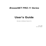
2.2.1
BU/RB-B130D/B300D-5X-GigE
Figure 2-5: BU/RB-B130D/B300D-5X-GigE Front Panel
Alvarion BreezeNET B130/B300 GigE
10
Technical User Manual
Chapter 2 - Hardware Description
Outdoor Units (ODU)
Figure 2-6: BU/RB-B130D/B300D-5X-GigE Top View
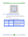
2.2.2
BU/RB-B130/B300-5X-GigE
Figure 2-7: BU/RB-B130/B300-5X-GigE Front Panel
Alvarion BreezeNET B130/B300 GigE
11
Technical User Manual
Chapter 2 - Hardware Description
Outdoor Units (ODU)
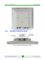
Figure 2-8: BU/RB-B130/B300-5X-GigE Top View
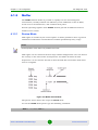
2.2.3
ODU LED Indicators Description
ODU units have two LED indicators (red and green) located in the Console
connector. These LEDs are useful in monitoring the device status during the
installation procedure. LEDs modes and Device status correspondence is shown
in the following table:
Table 2-2: ODU LED Indicators Description
Red Indicator
Green Indicator
Device Status
Off
Off
Device is switched off of in the process of start-up
booting
Off
Blinking
Device is booted. No radio connection. Searching for
another device to establish radio connection to.
Blinking
On
Radio connection established. The more data is
transmitted through the radio channel the more
frequently red indicator is blinking.
On
Off
MINT is stopped.
Alvarion BreezeNET B130/B300 GigE
12
Technical User Manual
Chapter 2 - Hardware Description
Installation Preparations
2.3
Installation Preparations
2.3.1
Required Components and Accessories
Before the installation, please make sure you have all necessary parts and
accessories:
Device
Antenna
Low loss antenna cable for the required frequency range
Antenna pole (if necessary)
Required grounding system
Accessories and tools
2.3.2
Antenna Placement
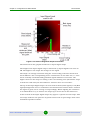
When planning an antenna placement for PTP link, in order to obtain the maximal
coverage range and best performance for the Device, one need to consider that
LOS requirements must be fulfilled for the path between two antennas. Moreover,
it is of vital importance that the certain zone that surrounds the signal
propagation path must be free from obstructions. One should understand that the
radio beam is not as thin as, for example, laser beam. Radio beam, also called as
a 1st Fresnel zone, has a profile of a rugby ball. Its exact form and size depend
upon the frequency and the signal propagation path length.
If most of the 1st Fresnel zone is obstructed, a major part of a electromagnetic
energy will be lost which leads to a severe signal quality degradation and, as a
result, to coverage range decreasing.
Below is an incomplete list of possible obstructions on the signal propagation
path:
Neighboring buildings
Trees
Bridges
Alvarion BreezeNET B130/B300 GigE
13
Technical User Manual
Chapter 2 - Hardware Description
Installation Preparations
Power lines
To obtain the best results, it is necessary to perform a precise analysis of a signal
propagation path zone and possible obstructions that may cover a part of the 1st
Fresnel zone (usually the analysis is performed at the highest points of the signal
propagation path).
NOTE
While planning, it is strongly recommended to consult high-qualified and experienced technicians
General recommendation for antennas placement are the following:
Install antennas as high as possible over specific level. In case of flat surface it will be ground level, in case of vegetation and forest - it will be tree heights,
in urban environment - it will be the highest building in the observed area
(specific level definition).
Avoid tree and vegetation along with wave propagation path, influence of trees
can increase depending on seasons (ice, dew, leaves);
Proximity of other antennas should be avoided (at least 2 meters);
Reflecting surfaces should be considered (building with reflective windows,
water surfaces or wet grounds);
When installing antenna over water surface, one should tune height bracket
within 1-3 meter range variation, because it can yield signal level variation
from minimum to maximum.
If seasonal changes influence on the signal quality, so then the most probable
reasons would be either the connectors are not protected enough from
humidity, summer vegetation or ice covered cabling and connectors during
winter.
2.3.3
Antenna Poles Usage
Antenna installation is performed on a special facility called antenna pole. The
pole is used for strong antenna tightening at the installation site. Poles might have
different modifications depending on the installation requirements.
Alvarion BreezeNET B130/B300 GigE
14
Technical User Manual
Chapter 2 - Hardware Description
2.3.4
Installation Preparations
Poles with Stretching
Usually this kind of poles are used when installing antenna on a flat surface and
permits one to raise it to a significant height for providing optimal conditions for
signal propagation.
2.3.5
Wall Mounted Pole
Usually these kinds of poles are used when there is no need to elevate antenna to
the rooftop and there is the possibility to mounting it on a wall. This installation is
significantly simpler than that implementation with poles. Mostly it is used for
subscriber side deployments.
2.3.6
Antenna Poles Requirements
Ease of antenna mounting and sufficient mechanical durability should provide
reliable fastening in conditions of high windy loads. Poles should have round
profile for ease of azimuth adjustment. Typical pole diameter is 30 to 50 mm.
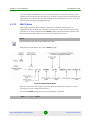
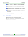
2.3.7
Grounding when Using IDU-BS-G
Antenna should be placed on the mast on the level that is at least 1 meter lower
than a mast's top. In this case it is of big probability that the lightning strikes the
mast and not the antenna. The mast is to be grounded on the grounding contour
according to your local standards. When the lightning strikes the antenna, the
current goes through the coaxial cable which grounds ODU clamp with the mast the mast is grounded via the grounding contour. The direct lightning strike to the
STP service cable (ODU-IDU) is partially terminated on the grounded IDU case.
Partial termination means that the direct lightning strike will probably destroy an
STP cable. The service cable pickups from the electromagnetic impulses are
terminated on the IDU case by the winding shield, and further - on the IDU
grounding. IDU is grounded via a three-conductor power cord and a plug
containing a ground. The data & power wires pickups are terminated via IDU
protection scheme (three-conductor power cord and a plug containing a ground).
CAUTION
Antenna pole, tower, ODU and lightning arrestor should be connected to the first common
grounding contour. Cable thickness should be no less than 10AWG using corrosion-steady
connectors. It is highly recommended to entrust grounding contour development to the skilled
personnel.
A special attention should be paid if antenna used is not DC-shorted. In this case
additional lightning arrestor should be used between the antenna and ODU.
Suggested grounding diagram is shown on the picture below.
Alvarion BreezeNET B130/B300 GigE
15
Technical User Manual
Chapter 2 - Hardware Description
Installation Preparations
Figure 2-9: Grounding
2.3.8
Antenna Alignment
To obtain maximal system performance antennas must be precisely aligned one
towards another according to LOS requirements. General recommendations for
antenna alignment are the following:
Align antennas using optical equipment (binoculars, spyglass) accompanied
by mobile phone actions coordination
Use GPS receiver and area map
Use build-in Device features. These features allow evaluating current
channel/signal quality and perform precise antenna alignment
2.3.9
Precaution Measures
Before you start the installation please read this section very carefully.
Alvarion BreezeNET B130/B300 GigE
16
Technical User Manual
Chapter 2 - Hardware Description
Installation Preparations
Antennas are installed on the roof tops or on the building walls. This work must
be accomplished only by personnel having special skills and experience in this
area.
Antennas and cables are electric conductors. Incidental electrostatic strikes may
occur during the system installation. This can lead to equipment damaging or
may hurt the personnel. While installing or changing the elements of the
antenna-feeder system one should make sure that open metal parts are
temporarily grounded.
Do not install the antenna close to the electric power lines. Antenna and antenna
pole have to be installed in such a way that while their assembling, disassembling
and repairing they did not have any contact with power lines.
Basic precaution measures that must be fulfilled during the installation are the
following:
Do not stay on the roof top in windy or rainy weather, during the
thunderstorm or when the working zone is covered with snow or ice
Do not touch the antennas, antenna poles, cables and lighting arrestors
during the thunderstorm
Antenna placement should not be close to electric or telephone lines. Safe
distance is a distance that is a sum of the two antenna poles heights and
antenna height
2.3.10 Service Cable Soldering Procedure
The following instruction shows the "RJ-45" (modification 2) connector soldering
procedure.
Alvarion BreezeNET B130/B300 GigE
17
Technical User Manual
Chapter 2 - Hardware Description
Installation Preparations
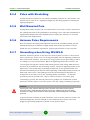
Table 2-3: RJ-45 Connector Soldering Procedure
Illustration
Description
Step 1. Peel STP service cable and
prepare "RJ-45" connector parts.
Use RJ-45 connector without
grounding here (RJ-45 connector
with grounding is used for
connecting service cable to IDU).
Step 2. Stick rubber filler - 5 on the
Part 4, previously having removed
protective white layer from rubber
filler -5.
Insert Part 2 inside part 4 up to the
stop. Part 2 must be entirely within
Part 4.
Alvarion BreezeNET B130/B300 GigE
18
Technical User Manual
Chapter 2 - Hardware Description
Installation Preparations
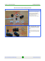
Table 2-3: RJ-45 Connector Soldering Procedure
Illustration
Description
Step 3. Put connector parts on the
STP service cable as shown.
Attach RJ-45 connector without
grounding to the STP service cable
according to the "RJ-45" soldering
scheme (in the "Supplementary
information" chapter of this manual)
and crimp the connector using a
crimp tool.
Please tightly crimp the
RJ-45 connector. Not
crimped or badly crimped
connector damages the
unit when assembled into
it which is not considered
as a warranty case.
Step 4. Put Part 4 on the attached in
the previous step RJ-45 connector.
Step 5. Screw Part 2 on Part 4. This
fixes the "RJ-45" connector on the
cable. Check that the connector is
properly fixed on the cable.
Alvarion BreezeNET B130/B300 GigE
19
Technical User Manual
Chapter 2 - Hardware Description
Installation Preparations
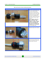
Table 2-3: RJ-45 Connector Soldering Procedure
Illustration
Description
Step 6. Assemble the connector to
the unit.
Step 7. Fix the connector by
screwing Part 3.
Now the connector is hermetically
attached to the unit.
2.3.11 Tools Required at the Installation Site
1
Screwdrivers set
2
Pliers
3
Soldering iron 40 W
4
Spanners set
Alvarion BreezeNET B130/B300 GigE
20
Technical User Manual
Chapter 2 - Hardware Description
5
6
Installation Preparations
Connectors isolating set
»
Raw rubber
»
Thermal shrinkage tube
»
Scissors
»
Fan
»
Mantling gun
Additional equipment
»
GPS receiver or area map (with compass and alidade)
»
Big zoom binoculars
Alvarion BreezeNET B130/B300 GigE
21
Technical User Manual
Chapter 2 - Hardware Description
BU/RB-B130D/B300D-5X-GigE
2.4
BU/RB-B130D/B300D-5X-GigE
2.4.1
Installation Guidelines
1
Unpack the equipment
2
Check items integrity
3
Prepare RF-cables of the required length. The recommended maximal RF cable
length is 1 meter.
4
Install and isolate the connectors on the RF cables
Figure 2-10: BU/RB-B130D/B300D-5X-GigE Installation 1
5
Determine the STP cable length that is used to connect IDU and ODU. The
total cable length between LAN (behind IDU) and ODU should not be longer
than 100 meters. Service cable connecting IDU and ODU should be STP Cat
5E cable.
6
Install (solder) connector for ODU on the STP cable and isolate it
7
If it is possible to lay STP cable with a connector on the IDU side, install
(solder) connector for IDU on the STP cable and isolate it
8
Lay the STP cable "from top to bottom" - from ODU to IDU
9
If step 7 is not accomplished, after the STP cable has been laid, install (solder)
connector for IDU
10 Install ODU on the mounting bracket connectors down and tighten it
Alvarion BreezeNET B130/B300 GigE
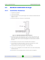
22
Technical User Manual
Chapter 2 - Hardware Description
BU/RB-B130D/B300D-5X-GigE
11 Connect the ODU-IDU cable to the ODU
12 Isolate the ODU connector joint place
13 Once the antenna and antenna pole are installed they must be grounded via
lightning protection grounding contour. Antenna's position must be lower than
the highest antenna pole point at least by 2 antenna heights. If antenna is
NOT DC-shorted (see antenna technical documentation), the additional
lightning arrestor must be used which is placed between ODU and antenna
and is grounded to the antenna pole grounding contour.
Figure 2-11: BU/RB-B130D/B300D-5X-GigE Installation 2
14 Connect RF cables to the antenna. Twist the connectors tightly
15 Connect RF cables to the ODU previously having touched RF cable connectors
case with ODU connector case
16 Isolate RF connectors from both sides (ODU and antenna)
17 Connect the STP cable to IDU previously having touched IDU connector case
with STP cable connector case
18 Provide grounding for IDU
Alvarion BreezeNET B130/B300 GigE
23
Technical User Manual
Chapter 2 - Hardware Description
BU/RB-B130D/B300D-5X-GigE
19 Connect Ethernet cable to IDU
20 Provide power supply for IDU
21 Connect to the Device using Telnet protocol
CAUTION
It is extremely important to install ODU connectors down!
Alvarion BreezeNET B130/B300 GigE
24
Technical User Manual
Chapter 2 - Hardware Description
BU/RB-B130/B300-5X-GigE
2.5
BU/RB-B130/B300-5X-GigE
2.5.1
Installation Guidelines
1
Unpack the equipment
2
Check items integrity
3
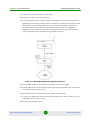
Determine the STP cable length that is used to connect IDU and ODU. The
total cable length between LAN (behind IDU) and ODU should not be longer
than 100 meters.
Figure 2-12: BU/RB-B130/B300-5X-GigE Installation 1
4
Install (solder) connector for ODU on the STP cable and isolate it
5
Lay the STP cable "from top to bottom" - from ODU to IDU
6
After the STP cable has been laid, use distribution box to switch from STP
cable to UTP cable with RJ-45 connectors. Service cable connecting IDU and
ODU should be STP Cat 5E cable.
7
Install ODU on the mounting bracket according to the direction required for
the link. Do not tight it too hard unless the antenna alignment is not complete.
Install ODU connectors down.
Alvarion BreezeNET B130/B300 GigE
25
Technical User Manual
Chapter 2 - Hardware Description
BU/RB-B130/B300-5X-GigE
8
Connect the ODU-IDU cable to the ODU
9
Isolate the ODU connector joint place
10 Once the ODU and antenna pole are installed they must be grounded via
lightning protection grounding contour. ODU position must be lower than the
highest antenna pole point at least by 2 ODU heights
Figure 2-13: BU/RB-B130/B300-5X-GigE Installation 2
11 Connect the UTP cable to IDU
12 Provide grounding for IDU
13 Connect Ethernet cable to IDU
14 Provide power supply for IDU
15 Connect to the Device using Telnet protocol
CAUTION
It is extremely important to install ODU connectors down!
Alvarion BreezeNET B130/B300 GigE
26
Technical User Manual
Chapter 2 - Hardware Description
2.6
Mounting Kit (MOUNT-KIT-85)
Mounting Kit (MOUNT-KIT-85)
The default mounting kit packed with all the device models is MOUNT-KIT-85.
MOUNT-KIT-85 features:
Material: casted Aluminum
Adjustment: two axis (vertical and horizontal)
Mounting options:
»
standard pole (30-85 mm)
»
wall
»
thick pipe (>85 mm, horizontal/vertical) using additional fasteners (not
included to the package)
RoHS compliant
Alvarion BreezeNET B130/B300 GigE
27
Technical User Manual
Chapter 2 - Hardware Description
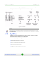
2.6.1
Mounting Kit (MOUNT-KIT-85)
Assembly
Figure 2-14: Mounting Kit
Alvarion BreezeNET B130/B300 GigE
28
Technical User Manual
Chapter 2 - Hardware Description
Mounting Kit (MOUNT-KIT-85)
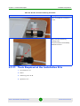
Figure 2-15: Mounting Instructions
2.6.2
Possible Variants of the Installation
Figure 2-16: Installation Variants
Alvarion BreezeNET B130/B300 GigE
29
Technical User Manual
Chapter 2 - Hardware Description
Mounting Kit (MOUNT-KIT-85)
CAUTION
MOUNT-KIT-85 does NOT contain worm drive hose clamps or other additional fixtures used in
possible variants of installation.
Alvarion BreezeNET B130/B300 GigE
30
Technical User Manual
Chapter 2 - Hardware Description
Specifications
2.7
Specifications
2.7.1
Radio
Table 2-4: Radio Specifications
Item
Description
Frequency
ETSI (5.470 - 5.725 GHz)
Center frequencies range 5.475 - 5.720 GHz
(in 5MHz steps) for 5MHz BW
Center frequencies range 5.475 - 5.720 GHz
(in 5MHz steps) for 10MHz BW
Center frequencies range 5.480 - 5.700 GHz
(in 20MHz steps) for 20MHz BW
Center frequencies range 5.490 - 5.690 GHz
(in 20MHz steps) for 40MHz BW
ETSI (5.725 - 5.875 GHz)
Center frequencies range 5.730 - 5.870 GHz
(in 5MHz steps) for 5MHz BW
Center frequencies range 5.730 - 5.870 GHz
(in 5MHz steps) for 10MHz BW
Center frequencies range 5.740 - 5.860 GHz
(in 20MHz steps) for 20MHz BW
Center frequencies range 5.750 - 5.850 GHz
(in 20MHz steps) for 40MHz BW
FCC (4.940 - 4.990 GHz)
Center frequencies range 4.945 - 4.985 GHz
(in 5MHz steps) for 5MHz BW
Center frequencies range 4.945 - 4.985 GHz
(in 5MHz steps) for 10MHz BW
Center frequencies range 4.960 GHz for
20MHz BW
Center frequencies range 4.970 GHz for
40MHz BW
Alvarion BreezeNET B130/B300 GigE
31
Technical User Manual
Chapter 2 - Hardware Description
Specifications
Table 2-4: Radio Specifications
Item
Description
FCC (5.250 - 5.350 GHz)
Center frequencies range 5.255 - 5.345 GHz
(in 5MHz steps) for 5MHz BW
Center frequencies range 5.255 - 5.345 GHz
(in 5MHz steps) for 10MHz BW
Center frequencies range 5.260 - 5.340 GHz
(in 20MHz steps) for 20MHz BW
Center frequencies range 5.270 - 5.330GHz (in
20MHz steps) for 40MHz BW
FCC (5.470 - 5.725 GHz)
Center frequencies range 5.475 - 5.720 GHz
(in 5MHz steps) for 5MHz BW
Center frequencies range 5.475 - 5.720 GHz
(in 5MHz steps) for 10MHz BW
Center frequencies range 5.480 - 5.700 GHz
(in 20MHz steps) for 20MHz BW
Center frequencies range 5.490 - 5.690 GHz
(in 20MHz steps) for 40MHz BW
FCC (5.725 - 5.850 GHz)
Center frequencies range 5.730 - 5.845 GHz
(in 5MHz steps) for 5MHz BW
Center frequencies range 5.730 - 5.845 GHz
(in 5MHz steps) for 10MHz BW
Center frequencies range 5.740 - 5.840 GHz
(in 20MHz steps) for 20MHz BW
Center frequencies range 5.750 - 5.830 GHz
(in 20MHz steps) for 40MHz BW
Universal
Center frequencies range 4.915 - 5.945 GHz
(in 5MHz steps) for 5MHz BW
Center frequencies range 4.915 - 5.945 GHz
(in 5MHz steps) for 10MHz BW
Center frequencies range 4.920 - 5.940 GHz
(in 20MHz steps) for 20MHz BW
Center frequencies range 4.930 - 5.930 GHz
(in 20MHz steps) for 40MHz BW
Modulation
OFDM modulation, BPSK, QPSK, QAM16, QAM64
Radio Type
OFDM TDD
Channel BW
5 MHz / 10 MHz / 20 MHz / 40 MHz
Maximal Net Throughput
250 Mbps
Alvarion BreezeNET B130/B300 GigE
32
Technical User Manual
Chapter 2 - Hardware Description
Specifications
Table 2-4: Radio Specifications
Item
Description
Output Power (at antenna port)
Up to 18 dBm (dependant upon regulation)
2.7.2
Antenna
Table 2-5: Antenna Specifications
Item
Description
External Antenna
ANT, T.S, 4.9-6 GHz, 9°, dual polarized, 23 dBi / ANT, T.S, 4.9-6
GHz, 6°, dual polarized, 28 dBi
Integrated Antenna
ANT, T.S, 4.9-6 GHz, 9°, dual polarized, 23 dBi
2.7.3
Data Communication
Table 2-6: Data Communication Specifications
Item
Description
Standard and Network Compliance
IEEE 802.3 CSMA CD, ARP filter/proxy, MAC/IP filtering, layer 2
switch, Ethernet 10/100/1000BaseT
VLAN Support
802.1q transparent or frame tagging and re-tagging
QoS
QoS enforcer classification and traffic limiting based on: IP
ToS/DSCP/802.1p tags, VLAN/IP/MAC address and protocol
Security
Storm/flood protection, password protection, over-the-air payload
encryption, IP Firewall
2.7.4
Configuration Management
Table 2-7: Configuration Management Specifications
Item
Description
Management Options
Configure/monitor SNMP traps, WEB interface, CLI (telnet, serial
console, remote shell)
Remote Management Access
From wired LAN, wireless link
Allocation of IP Address
DHCP client / server / relay
SW Upgrade
Via FTP / WEB interface
Configuration Upload / Download
Via FTP / WEB interface
SNMP Agents
SNMP V1 / SNMP V3, MIB II, private MIB
Alvarion BreezeNET B130/B300 GigE
33
Technical User Manual
Chapter 2 - Hardware Description
2.7.5
Specifications
Electrical Characteristics
Table 2-8: Electrical Characteristics Specifications
Item
Description
Power Consumption
Up to 20W
Input Power
AC, 100-240 VAC, 50-60 Hz (DC 10.5-32 UDC with OPS-DC add-on
module)
Indoor-outdoor Cable
CAT-5 shielded, 90m max
AC Power Indoor Unit
3 pin AC power plug
Connectors
RJ-45
2.7.6
Physical and Environmental
Table 2-9: Physical and Environmental Specifications
Item
Description
Dimensions RB/BU
IDU: 5 x 4 x 2 cm (0.14 kg) / ODU with integrated antenna: 30 x 30 x
8 cm (3.7 kg) / ODU with external antenna 24 x 24 x 5 cm (2.1 kg)
Operating Temperature
ODU: -40°C to 60°C / IDU: 0°C to 40°C
Operating Humidity
ODU: 100% humidity, condensing (exceeds IP65 rating) / IDU: 95%
humidity, non-condensing
2.7.7
Standards and Regulations
Table 2-10: Standards and Regulations Compliance
Item
Description
Radio
ETSI EN 301 893 V1.5.1 / ETSI EN 302 502 V1.2.1
EMC
ETSI EN 301 489-1 V1.4.1
Protection and Safety
ETSI EN 60950-1
Alvarion BreezeNET B130/B300 GigE
34
Technical User Manual
Chapter
3
Basic Configuration Instructions
Chapter 3 - Basic Configuration Instructions
In This Chapter:
“Initial Settings Configuration Procedure” on page 37
“Device Interfaces” on page 39
“Command Line Interface (CLI)” on page 40
“Lost Password Recovery” on page 41
“Configuration Manipulations” on page 45
“Ethernet Interface Configuration” on page 47
“Radio Interface Configuration” on page 48
Alvarion BreezeNET B130/B300 GigE
36
Technical User Manual
Chapter 3 - Basic Configuration Instructions
3.1
Initial Settings Configuration Procedure
Initial Settings Configuration Procedure
Before starting new device, one should perform initial configuration. The
configuration can be performed either using serial console port or using Telnet
protocol. In order to configure the device using Console port, follow the
instructions below:
Device should be connected with host (e.g. Hyper Terminal)
Set serial interface properties to 38400 baud rate, 8 bit, 1 stop bit, parity off,
flow control disabled
Enable emulation mode ANSI or VT100, keyboard VT100
To connect using Telnet protocol from the wired LAN run Telnet with 10.10.10.1
IP-address that is configured for the Ethernet interface of the device by default.
If all above procedures are completed correctly, you will see the WANFleX OS
prompt:
Login:
Every new device has got default login and password settings as written below:
Login: admin
Password: private
After default authorization there will be standard console prompt:
console>
Now the device is ready for the initial configuration procedure. The most relevant
thing to be done at this phase is to define device name/user/password.
system name Test
system user root
system password qwerty
Alvarion BreezeNET B130/B300 GigE
37
Technical User Manual
Chapter 3 - Basic Configuration Instructions
Initial Settings Configuration Procedure
NOTE
Part of commands in bold must be typed in CLI (Command Line Interface). The rest of the
command name is optional and can be skipped while typing.
Once this is completed, ONLY the specified username and password can be used
to access the device. DO NOT FORGET THESE PARAMETERS.
Alvarion BreezeNET B130/B300 GigE
38
Technical User Manual
Chapter 3 - Basic Configuration Instructions
3.2
Device Interfaces
Device Interfaces
The Device has several physical and logical interfaces:
lo0 - loopback interface, used for system interaction needs
null0 - logical interface, can be used for auxiliary addresses assignation (for
NAT module, for example); for routes aggregation for RIP protocol. Addresses
(subnets) are announced to the network but every packet transmitted through
this interface is destroyed
eth0 - Ethernet 10/100/1000 Mbits interface
rf5.0 - radio interface. See device's labeling it learn your radio interface name
vlanX - interfaces supporting VLAN 802.1q tagging
All configured interfaces of the device can be reviewed using the following
command:
ifconfig -a
Alvarion BreezeNET B130/B300 GigE
39
Technical User Manual
Chapter 3 - Basic Configuration Instructions
3.3
Command Line Interface (CLI)
Command Line Interface (CLI)
For device's management and configuration a Unix-like command line language is
used. Every command starts having the power right after Enter key is pressed.
However, each command lifetime duration is limited within one configuration
session. In order to save a current configuration "config save" command is used.
Several commands can be grouped in one line using ";" character. If a
wrong-syntax line is met in the group, the rest of the string is checked anyway
and the wrong command is ignored. Command name can be shortened unless the
ambiguity occurs.
If your terminal supports VT100 or ANSI standard you can move around the list of
recently executed commands using cursor keys. Numbered list of these
commands can be reviewed by "!h" command. Any command from this list can be
available using "!<NUMBER>" command. TAB key performs substring search of
recently executed commands.
Ctrl/R combination refreshes the command string if its content was disturbed by
system messages.
The command executed with no arguments prints a short hint about its keys,
parameters and syntax.
Context help can be obtained by printing "?" in any position of the line.
Alvarion BreezeNET B130/B300 GigE
40
Technical User Manual
Chapter 3 - Basic Configuration Instructions
3.4
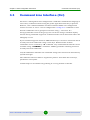
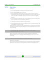
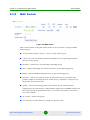
Lost Password Recovery
Lost Password Recovery
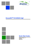
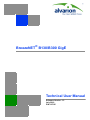
The password for the device can be recovered remotely.
Recovery procedure can be done with the help of graphical "ERConsole" utility.
Figure 3-1: ERConsole (Step 1)
Below is a description of ERConsole’s utility recovery procedure:
1
Connect a computer and a device that should be repaired to one physical
Ethernet segment.
NOTE
It is recommended to put a switch between the unit and the PC from which ERConsole is executed.
2
Start the ERConsole utility on the computer by running the ERConsole.jar file.
Utility will be running in a waiting mode.
Alvarion BreezeNET B130/B300 GigE
41
Technical User Manual
Chapter 3 - Basic Configuration Instructions
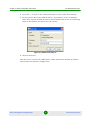
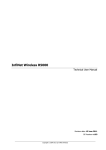
3
Lost Password Recovery
Restart the device. During its restart, the ERConsole utility will determine the
device and will show necessary information about it in the "Discovered
devices" section of the main window.
Figure 3-2: ERConsole (Step 2)
4
Send "Serial" and "Sequence" fields values to the Technical Support.
5
You will be given a factory password for the device.
6
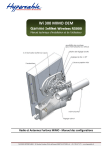
Click the "+" button in the "Scheduled tasks" section of the main window.
7
In the opened "New task" window choose "Reset configuration" in the
"Command" field. Then enter Serial number and factory password in the
corresponding fields. Click "Ok".
Alvarion BreezeNET B130/B300 GigE
42
Technical User Manual
Chapter 3 - Basic Configuration Instructions
Lost Password Recovery
Figure 3-3: ERConsole (Step 3)
8
Restart the device.
After device restart the ERConsole utility will reset device configuration.
CAUTION
The ERConsole reports as "complete" also a failed action because it does not have a mechanism to
verify if the unit accepted the password or not.
9
Login the device with Serial number as a login name and new password that
was received from tech support.
CAUTION
Password must be inserted without spaces in order to be accepted by the device.
10 Reconfigure device username and password.
CAUTION
The "config clear" command followed by a reboot must be performed in order to make available the
radio interface and start unit configuration from default settings.
The ERConsole utility's "New task" window also allows setting the unit's
IP-address on its Ethernet interface (eth0) without login to device. To perform this
procedure, follow the steps below:
1
Firstly, do steps 1-3 as described above.
Alvarion BreezeNET B130/B300 GigE
43
Technical User Manual
Chapter 3 - Basic Configuration Instructions
Lost Password Recovery
2
Press the "+" button in the "Scheduled tasks" section of the main window.
3
In the opened "New task" window choose "Up interface" in the "Command"
field. Then type the wanted IP-address and network mask in the corresponding
fields of the window and press the "OK" button.
Figure 3-4: ERConsole (Step 4)
4
Restart the device.
After the device restarts, the "ERConsole" utility will add the wanted IP-address
into its Ethernet interface configuration.
Alvarion BreezeNET B130/B300 GigE
44
Technical User Manual
Chapter 3 - Basic Configuration Instructions
Configuration Manipulations
3.5
Configuration Manipulations
3.5.1
Printing and Saving Your Configuration
You can easily review your current device's configuration by executing "config
show" command. The output of the command is sorted by the configuration
sections (e.g. "System parameters", "Interfaces configuration" etc).
You can review some particular parts of the configuration specifying the part of
the configuration you want to see.
Example:
config show ifc
This command will print the interfaces configuration.
In order to save your configuration "config save" command is used. It saves the
current system configuration in the device's flash memory for subsequent
permanent use. All modifications to the system parameters, if not saved by this
command, are valid only during the current session (until the system reset
occurs).
3.5.2
Import/Export
Export/import of the device's configuration is performed using "config export" and
"config import" commands correspondingly. "Config export" saves the device
configuration on a remote server and "config import" reloads it from a remote
server. The information is transferred using FTP.
Example:
config export user:[email protected]/var/conf/test.cfg
"Config import" command writes the uploaded file directly into the Flash memory
without changing the active configuration in RAM. In order to make a new
configuration active, right after "config import" command implementation
finishes the device should be rebooted. If "config save" command is run before
rebooting, Flash memory is overwritten by the copy of the active configuration.
This action will erase the uploaded configuration file.
3.5.3
IP Address Formats
Many commands of the operating system require specification of IP addresses.
Alvarion BreezeNET B130/B300 GigE
45
Technical User Manual
Chapter 3 - Basic Configuration Instructions
Configuration Manipulations
In OS WANFleX, the IP-addressees may be specified in traditional numeric format.
Optionally, the mask may be specified either by its bit length (the specified
number of leading bits in the mask are set to 1, the remaining bits are reset to 0)
or numeric value. The IP address 0/0 denotes all possible IP addresses.
Therefore, the possible formats to specify IP-addresses are:
nn.nn.nn.nn (no mask is used)
nn.nn.nn.nn/N (N is the bit length of the mask)
nn.nn.nn.nn:xxx.xxx.xxx.xxx (xxx.xxx.xxx.xxx is the numerical value of the mask)
Example:
The 192.168.9.0/24 address describes the network address 192.168.9.0 and the
mask with leading 24 bits on.
The same set of addresses may be denoted as 192.168.9.0:255.255.255.0.
Alvarion BreezeNET B130/B300 GigE
46
Technical User Manual
Chapter 3 - Basic Configuration Instructions
3.6
Ethernet Interface Configuration
Ethernet Interface Configuration
In the most basic form Ethernet interface can be configured as follows:
ifconfig eth0 1.1.1.1/24 up
UP flag means than the interface is turned to UP state.
Also you can specify the following parameters for the Ethernet interface:
Media type. By default media type is selected automatically (media auto
parameter).
Assign aliases to the Ethernet interface (alias key word)
Full information about interfaces configuration can be reviewed in OS WanFlex
User Guide - ifconfig command.
Alvarion BreezeNET B130/B300 GigE
47
Technical User Manual
Chapter 3 - Basic Configuration Instructions
3.7
Radio Interface Configuration
Radio Interface Configuration
Radio interface configuration is performed using "rfconfig" command. In its most
basic form one need to configure the following parameters of the radio interface:
Frequency (freq parameter) in MHz. For example, 5260.
Bitrate (bitr parameter). Bit transfer rate in kBits/sec.
System identifier (SID parameter). A hexadecimal number in the range of 1H to
FFFFFFH. All devices that are supposed to see each other on the same radio
link must have the same identifier.
NOTE
Radio interface state is not saved in the configuration. That means that if you put radio interface to
the down state after rebooting it will be in the up state.
To learn your device's radio module capabilities type the command:
rfconfig <IF-NAME> capabilities
<IF-NAME> - radio interface name. Can be read on the device's labeling located on
the case.
Radio interface configuration is performed using "rfconfig" command.
Example:
rfconfig rf5.0 freq 5260 bitr 130000 sid 01010101
Additional important parameters and settings for the radio interface:
rf5.0 - radio interface name in this case. In order to obtain radiointerface
name either see the ODU/Device labeling or execute "ifc -a" command.
txpwr - transmitting power selection. Available power levels can be obtained
using "capabilities" parameter as shown above.
Example:
Alvarion BreezeNET B130/B300 GigE
48
Technical User Manual
Chapter 3 - Basic Configuration Instructions
Radio Interface Configuration
rfconfig rf5.0 freq 5260 bitr 300000 sid 10203040
rfconfig rf5.0 txpwr 18
Alvarion BreezeNET B130/B300 GigE
49
Technical User Manual
Chapter
4
Link Configuration
Chapter 4 - Link Configuration
In This Chapter:
“Link Diagnostic Tools” on page 52
Alvarion BreezeNET B130/B300 GigE
51
Technical User Manual
Chapter 4 - Link Configuration
Link Diagnostic Tools
4.1
Link Diagnostic Tools
4.1.1
Ltest
Ltest utility allows precise test of a radio link. It is recommended for antenna
alignment when installing a new device or for testing of existing radio link.
Ltest can work in standard, alignment and bandwidth modes.
Standard mode:
In standard mode Ltest measures signal levels, retries, lost packets and acks.
To start Ltest in this mode:
ltest rf5.0 <Mac-address of a device on the other side of the radio link>
When "ltest" command starts it will show you output information that contains
testing results. You can see Ltest output below:
Figure 4-1: Ltest
For successful radio link establishing the following factors have to be considered:
Alvarion BreezeNET B130/B300 GigE
52
Technical User Manual
Chapter 4 - Link Configuration
1
Link Diagnostic Tools
It is recommended to start antenna alignment with searching maximum signal
level on a minimal possible bitrate. Afterwards automatic MINT mechanisms
will set the most appropriate bitrate if autobitrate mode will be enabled.
2
Current incoming signal level in "amp/max" columns (see "ltest" command
output) must be between 12 and 40.
When it is more than 40 it is recommended to lower amplifier power.
If maximal signal level is less than 12 it is recommended to lower bitrate or
channel width (for example, from 20MHz to 10MHz on the both sides of the
radio link).
In some cases signal level that is less then 12 may be enough for radio link
operation. In this case one has to be guided by such parameters as number of
retries, number of undelivered packets and number of undelivered acks. If the
number of undelivered packets and the number of undelivered acks is null,
the number of retries is small and all these parameters are constant in time
then the radio link, most often, will be operating properly.
3
Number of retries value in "rt%" columns must be as close to zero as possible.
4
Number of undelivered packets value in "up%" columns must be zero; if this
value is not zero then the radio link couldn't be exploit.
5
Number of undelivered acks value in "ua%" columns must be zero; if this value
is not zero then the radio link couldn't be exploit.
ALL described parameters must be observed in the both (Local and Remote)
sections of the "ltest" command output.
Alignment mode:
The difference of this mode from the standard one is that "ant.amps" column is
used instead of "amp/max". "Ant.amps" column indicates signal levels for each of
two antennas of a device divided by ":" correspondingly.
To start Ltest in this mode:
ltest rf5.0 <Mac-address> -align [L,R]
Ltest output in alignment mode:
Alvarion BreezeNET B130/B300 GigE
53
Technical User Manual
Chapter 4 - Link Configuration
Link Diagnostic Tools
Figure 4-2: Ltest Align
Bandwidth mode (Bandwidth meter):
Bandwidth meter is used to test the following radio link characteristics: speed in
kilobits per second, speed in packets per second, number of retries and errors.
Use the following "ltest" command options for testing:
-tu [seconds] - Unidirectional test: packets are transmitted only from the
current side to the specified address ("target" option)
-tb [seconds] - Bidirectional test: packets are transmitted in both directions
"Seconds" parameter allows setting test period (5 seconds by default). Maximum
value is 60 seconds.
To start Ltest in this mode:
ltest rf5.0 <Mac-address> -tb
"Ltest" command output in Bandwidth meter mode:
Figure 4-3: Ltest Bandwidth Meter
Alvarion BreezeNET B130/B300 GigE
54
Technical User Manual
Chapter 4 - Link Configuration
4.1.2
Link Diagnostic Tools
Muffer
The muffer module makes it possible to rapidly test the electromagnetic
environment, visually estimate the efficiency of the utilization of the air links,
reveal sources of interference, and estimate their power.
Several operating regimes of the muffer module provide for different levels of
details in test results.
4.1.2.1
Review Mode
This regime is enabled by the review option. It makes possible to have a general
estimation of emissions and interference within specified frequency range.
NOTE
Normal operation of the radio is not possible in this mode.
This regime can be useful on the first steps of link configuration. One can observe
the activity on the selected list of frequencies and make decisions of what
frequencies can be used for the link so that the link did not interfere with other
sources of signals.
Figure 4-4: Muffer Review Mode
The picture above shows the output of review mode.
To run the review mode please type the following command:
muffer <IF-NAME> review
Alvarion BreezeNET B130/B300 GigE
55
Technical User Manual
Chapter 4 - Link Configuration
Link Diagnostic Tools
Once the link is established you can use this mode to review the activity on the
configured for frequency for the link. If no activity is observed that means that the
signal from the remote side is being broken by the interference sources or by the
obstacles on the signal propagation path.
4.1.2.2
MAC2 Mode
This regime performs MAC-address analysis to estimate the efficiency of
utilization of the air link. The analysis is carried out at the frequency previously
specified by rfconfig command. The mac2 regime checks both data packets and
the link-level ACK messages sent by protocol supported devices.
NOTE
Normal operation of the radio is not possible in this mode.
The picture below shows the output mac2 regime.
Figure 4-5: Muffer MAC2 Mode
Like in review mode this regime provides with the information about a current
activity but on the configured frequency.
To run the review mode please type the following command:
muffer <IF-NAME> mac2
Alvarion BreezeNET B130/B300 GigE
56
Technical User Manual
Chapter 4 - Link Configuration
4.1.2.3
Link Diagnostic Tools
Statistics
The statistics gathering is used for estimating link load intensity. The amount of
packets sent and received, and the number of retransmissions is shown for each
MAC address participating in the data exchange.
The statistics output is presented in the picture below.
Figure 4-6: Muffer Statistics Mode
The following decisions can be made by analyzing the outputted parameters:
If the number of repeated packets is comparable with total number of packets
that means that you might have an interference source on the selected
frequency. For normally operating link the percentage of repeated packets
should not exceed 10%. It is extremely important to obtain a permanent zero
value for the average number of repeats per packet. If the value is not zero that
means that the link is NOT working properly and requires further
improvement
If total percentage of repeated packets and the percentage of packets that were
repeated at least once are close to each other that might mean that you have
got a permanent source of interference. Otherwise, it means that a strong
interference source appears from time to time breaking your signal
Concerning the fact that statistics module outputs the information for each
MAC-address separately, you can reveal the problem for some specific unit on
the wireless network
The "muffer stat" command shows the statistics only from registered devices.
To view statistics type the following command:
muffer stat
To reset all counters please type
muffer stat clear
4.1.2.4
Other Modes of Muffer
The muffer also has the following modes:
Alvarion BreezeNET B130/B300 GigE
57
Technical User Manual
Chapter 4 - Link Configuration
Link Diagnostic Tools
mac mode. Compared to the mac2 mode this mode does not take link-level
ACK messages sent by protocol support devices into account
mac2 mode. This mode is used to detect impulse interference and doesn't
disturb radio model normal operation.
mac3 mode. Compared to mac2 mode this mode also performs calculation of
impulse interference.
mynet mode. This mode performs the radio testing without disturbing radio
module's normal operation, but taking into account only packets from within
the given network
Sensor mode. In this mode shows the radio environment testing results on the
screen in a visual-digital format.
4.1.3
Load Meter
Load meter is a powerful tool that allows estimating the load of a system interface
specified by interface parameter. By default, the information is displayed on one
line and updated every second; the load is measured in kilobytes.
Below picture shows the load meter output for the radio interface outputted in
line-by-line mode with one second interval.
Alvarion BreezeNET B130/B300 GigE
58
Technical User Manual
Chapter 4 - Link Configuration
Link Diagnostic Tools
Figure 4-7: Load Meter
To run load meter like it is shown above, please type:
loadm -l <IF-NAME>
4.1.4
Acquiring Interfaces Statistics
Interface statistics can be acquired using netstat module which includes two
modes:
Routing tables output (using "-r" parameter with the command)
Alvarion BreezeNET B130/B300 GigE
59
Technical User Manual
Chapter 4 - Link Configuration
Link Diagnostic Tools
Interfaces statistics output (using "-i" parameter with the command)
Below picture shows the example of interfaces statistics output.
Figure 4-8: Netstat
NOTE
If the interface has several aliases the statistics is still measured for physical interface in a whole.
For example, see rf5.0 or eth0 interfaces above. The numbers shown in 4 right columns correspond
in physical interface.
4.1.5
RapidView
RapidView - is a special diagnostic device that is used for equipment comfort
installation, antenna alignment and configuration.
Device allows getting the following information:
Radio link establishment indication
Visual monitoring of radio signal levels
Receiving retries information
Diagnostic of RF and Ethernet interfaces
Alvarion BreezeNET B130/B300 GigE
60
Technical User Manual
Chapter 4 - Link Configuration
Link Diagnostic Tools
Figure 4-9: RapidView Top
Alvarion BreezeNET B130/B300 GigE
61
Technical User Manual
Chapter 4 - Link Configuration
Link Diagnostic Tools
Figure 4-10: RapidView Back
Figure 4-11: RapidView Indicator Panel
Alvarion BreezeNET B130/B300 GigE
62
Technical User Manual
Chapter 4 - Link Configuration
4.1.5.1
Link Diagnostic Tools
How to Use
Turning on:
1
For turning RapidView on simply push the "Power button".
2
Device LEDs will light up for 2 seconds.
3
Device will perform constant tries to connect to ODU. If device's power is
normal Power/ODU connection LED (1) will blink 1 time per second. If device's
power is low LED 1 will blink 4 times per second in turn with not lighting
intervals.
4
Once ODU link is established, LED 1 stops blinking (if power is normal) and
device's interfaces status are shown by LEDs 2-6.
5
1 time per second device updates its status output.
6
If ODU link will be broken, LEDs 2-6 will go out after 2 seconds and LED 1 will
start blinking 1 time per second.
Diagnostic device connection to ODU should be done via console port of the ODU.
Once link is up between ODU and diagnostic device the following record is put in
ODU system log:
Connected test unit. Begin service communication over console.
Test unit detected: rf0 - rf5.0
Exact radio interface names depend on wireless equipment configuration.
When diagnostic device is unplugged from the following record is put in ODU
system log:
Test unit disconnected. Return to normal console mode.
LEDs modes description:
ODU status monitoring via diagnostic device is performed by its LEDs indication.
LEDs modes and ODU status correspondence is shown in the following table:
Alvarion BreezeNET B130/B300 GigE
63
Technical User Manual
Chapter 4 - Link Configuration
Link Diagnostic Tools
Table 4-1: Indicator LEDs
LEDs
Function
1. Power/ODU
connection LED
Shows diagnostic device power status and diagnostic device-ODU connection
status.
Constant lighting - diagnostic device-ODU connection established,
diagnostic device power is normal.
Blinking 1 time per second - diagnostic device power is normal, diagnostic
device-ODU connection is not established.
Blinking 4 times per second - diagnostic device-ODU connection
established, diagnostic device power is low (change batteries).
Frequent blinking with intervals - diagnostic device power is low,
diagnostic device-ODU connection is not established.
2. Radio link LEDs
Show whether radio link is established on certain ODU's radio interface.
Constant lighting - radio link is established.
What ODU's radio interface to show by what column RF0 or RF1 is chosen by the
following way:
for RF0 column is taken radio interface with the least number, for RF1 the other
interface.
For example, there are the following radio interfaces on ODU:
rf5.0. Then for RF0 column rf5.0 will be taken, for RF1 - rf5.1.
When no radio link then LEDs 2-4 are not lighting.
3. Radio signal
overload/Packets
retries LEDs
Show receiving radio signal level overload and number of packet retries
information.
Constant lighting -receiving radio signal level on the interface is too high.
Blinking 4 times per second - number of retries >= 50%
Blinking 2 times per second - number of retries >= 28%
Blinking 1 time per second - number of retries >= 7%
If certain radio interface (radio module) is not present on the device then all
corresponding LEDs of this radio interface is off.
If ODU has certain radio interface but it is not activated (for example, not entered
"mint rf5.0 start" command) then LED 3 is blinking 1 time per second whereas
LEDs 2 and 4 are not lighting.
If ODU has certain radio interface but it is not activated (for example, not entered
"mint rf5.0 start" command) then LED 3 is blinking 1 time per second whereas
LEDs 2 and 4 are not lighting.
If ODU has certain radio interface activated ("mint rf5.0 start" command entered)
then LED 3 is blinking 4 times per second whereas LEDs 2 and 4 are not lighting.
Alvarion BreezeNET B130/B300 GigE
64
Technical User Manual
Chapter 4 - Link Configuration
Link Diagnostic Tools
Table 4-1: Indicator LEDs
LEDs
Function
4. Radio signal level
scales
Show receiving signal level of the established radio link.
Each LED can be in 4 modes:
Not lighting - radio signal level is lower than scale value.
Blinking - the more frequently is blinking the nearer signal level is to given scale
value.
Constant lighting - signal level is higher or equal to scale value.
5. Ethernet interface
speed LEDs
6. Ethernet interface
mode LEDs
Show speed of corresponding Ethernet interface.
There are LEDs for the Ethernet interface.
10 Mbps
100 Mbps
1000 Mbps
Error
Upper LED
Lighting
Not lighting
Lighting
Blinking
Lower LED
Not lighting
Lighting
Lighting
Blinking
Constant lighting - Full Duplex.
Not lighting - Half Duplex.
IF Ethernet connection is established but corresponding ODU's interface is not
enabled then LEDs 5, 6 indicate connection configuration by blinking 1 time per
second.
Alvarion BreezeNET B130/B300 GigE
65
Technical User Manual
Chapter
5
Configuration Via Web Interface
Chapter 5 - Configuration Via Web Interface
In This Chapter:
“Overall Functionality Overview” on page 68
“Run Requirements” on page 69
“Basic Settings” on page 70
“Device Status” on page 78
“Maintenance” on page 88
“Spectrum Analyzer” on page 89
Alvarion BreezeNET B130/B300 GigE
67
Technical User Manual
Chapter 5 - Configuration Via Web Interface
5.1
Overall Functionality Overview
Overall Functionality Overview
Web-interface is used for the following purposes:
View and change system parameters of the device
View and change system interface parameters of the device
View and change radio link parameters
View and change network parameters of the device
Monitoring statistics for all interfaces
Monitoring radio link statistics
Alvarion BreezeNET B130/B300 GigE
68
Technical User Manual
Chapter 5 - Configuration Via Web Interface
5.2
Run Requirements
Run Requirements
In order to run and properly use the application, the following requirements must
be met:
Web-browser
OS WANFleX for MINT
Web-interface support activated on the device ("webcfg start" command)
To connect to the device via Web-browser type: http://<device IP address> (by
default http://10.10.10.1).
CAUTION
Web session time-out is 30 minutes.
Alvarion BreezeNET B130/B300 GigE
69
Technical User Manual
Chapter 5 - Configuration Via Web Interface
5.3
Basic Settings
Basic Settings
Figure 5-1: Basic Settings
On the "Basic Settings" page the device configuration is performed. All the
parameters that are available for configuration are divided into the dedicated
sections (e.g. "General settings", "Radio Settings").
To show/hide the parameters of the section just click the section's header.
The listing and description of all the sections can be found below in this chapter.
To view the commands that will be executed on the device after pressing the
"Done" button, please use "Preview Configuration" button.
To apply the configuration changes to the unit use "Done" button.
NOTE
After pressing "Done" button unit's current configuration will be updated according to the
parameters set on the "Basic Settings" tab. Unit will be turned into the switch mode.
Alvarion BreezeNET B130/B300 GigE
70
Technical User Manual
Chapter 5 - Configuration Via Web Interface
5.3.1
Basic Settings
General Settings
Figure 5-2: General Settings
This section allows viewing/setting general parameters used for device access:
Device name - general device name
User Name - User Name used as Login
Password - Secret Password used to login to the unit
Confirm Password - Password confirmation
Keep current system password" check-box - saves currently used password in
the unit's configuration and locks "Password" and "Confirm Password" fields.
In case this check-box is leaved unchecked and "Password" and "Confirm
Password" fields are empty some web browsers may spontaneously put
random data into them so that after the configuration is applied the password
will be unknown to the user.
Alvarion BreezeNET B130/B300 GigE
71
Technical User Manual
Chapter 5 - Configuration Via Web Interface
5.3.2
Basic Settings
Radio Settings
Figure 5-3:
This section allows viewing/setting the following radio parameters:
Interface -available radio interface
Type - network type of the node (Master, Slave)
Channel Width - operating channel bandwidth of the radio in MHz. Must be
equal at both sides of the link
DFS - allows starting DFS (Dynamic Frequency Selection) service or DFS
without Radar Detection
Frequency - central operating frequency in MHz. Must be equal at both sides
of the link.
Frequency range list - list of frequencies allowed for choosing by DFS service
TX Power - output power of the radio in dBm. "Auto" field enables ATPC
function (recommended)
Tx Bitrate - fixed operating bitrate (if numerical value chosen) or auto bitrate
(Automatic Modulation Control) if "Auto" is chosen. "Autobitrate" is
recommended
Alvarion BreezeNET B130/B300 GigE
72
Technical User Manual
Chapter 5 - Configuration Via Web Interface
5.3.3
Basic Settings
Interface Settings
Figure 5-4: Interface Settings
This section allows viewing/setting the following network parameters:
ethX Settings - Ethernet interface settings (e.g. eth0):
"Up" check-box enables/disables the interface
"DHCP" check-box allows starting DHCP client on the interface
IP-address field allows assigning an IP-address to the interface. One can
assign more than one IP-address to the interface by using "+" button. "X"
button clears the corresponding IP-address. "Remove" button deletes the
corresponding IP-address.
rfX Settings - RF interface settings (e.g. rf5.0):
Please see "ethX Settings" description above.
Default Gateway - sets an IP-address for the Default Gateway.
Alvarion BreezeNET B130/B300 GigE
73
Technical User Manual
Chapter 5 - Configuration Via Web Interface
5.3.4
Basic Settings
Link Settings
Figure 5-5: Link Settings
This section allows viewing/setting the following link parameters:
Interface - available radio interface
Network SID - Network System Identifier (8-digit HEX figure). All units that are
supposed to see each other on the same radio link must have the same SID
value
Node Name - the network name for the node
Node ID - the sequential number for the node. The parameter is optional
Security Key - key word to encode protocol messages. The key can be up to 64
characters long and should not contain spaces (or should be put in quotes). All
units that are supposed to see each other on the same radio link must have
the same Security Key
Encryption - enables hardware-accelerated AES-128 encryption for all the
traffic
Marker Access - turns marker access (Polling) mode on. This mode is
recommended for long PTP links (7+ km). Should be enabled just at one side of
the PTP link (do not enable polling at both sides, otherwise wireless connection
will fail!)
Alvarion BreezeNET B130/B300 GigE
74
Technical User Manual
Chapter 5 - Configuration Via Web Interface
5.3.5
Basic Settings
MAC Switch
Figure 5-6: MAC Switch
This section allows stating the switch mode on the unit and creating multiple
switch groups.
"Create Switch Group" button - creates a new switch group
"ethX" and "rfx" check-boxes allows including the corresponding interfaces
into the switch group
Enabled - enables the corresponding switching group
STP - enables Spanning Tree Protocol feature at the switching group
IGMP - enables IGMP-Snooping feature at the switching group
Repeater - starts the repeater mode. In this mode the group switches the
packets simply by sending them to all the device's interfaces except the one
the packet was received from.
Admin - sets the switching group as the admin group. All the packets
originated by the unit itself (e.g. RIP/OSPF or ping) leave the MINT network via
the admin group. If "No Admin Group" is selected such packets isn't able to
leave the network
"X" button - deletes the group
Up and down arrows allows to change the group's order
Alvarion BreezeNET B130/B300 GigE
75
Technical User Manual
Chapter 5 - Configuration Via Web Interface
Basic Settings
Group Rules - allows adding rules that defines what packets should be
processed by the group
Default Action - the action (permit or deny) taken on the packet if it doesn't
match to any rule
Help - displays help guidelines for rules creation using "Group Rules"
subsection
Management VLAN - sets a Management VLAN ID. When set the device access
and configuration are possible only via Management VLAN
"Enable Switch" check-box - starts switching on the unit.
5.3.5.1
Group Rules
Figure 5-7: Group Rules
This subsection of the "MAC Switch" section allows adding rules that defines what
packets should be processed by the group.
Match - a field where a rule shall be typed in. To view the rules help please use
the "Help" button in the "MAC Switch" section (described above).
Validate - checks if the rule typed in the "Match" field has the right syntax
Action - the action (permit or deny) taken on the packet if it matches the rule
"X" button - deletes the rule
Up and down arrows allows to change the rule's order
New Rule - creates a new rule's entry in the "Group Rules" subsection
Alvarion BreezeNET B130/B300 GigE
76
Technical User Manual
Chapter 5 - Configuration Via Web Interface
5.3.6
Basic Settings
QoS Options
Figure 5-8: QoS Options
This section allows managing traffic prioritization.
5.3.6.1
Auto Prioritization
This set of check-boxes allows enabling/disabling automatic traffic prioritization
for different types of packets.
RTP Packets - enables automatic prioritization for real time packets
Dot1p Tags - enables automatic prioritization for packets labeled with IEEE
802.1p priority
IP ToS - enables automatic prioritization for packets labeled with ToS
TCP Acknowledgments - enables automatic prioritization for TCP Acks.
5.3.6.2
Miscellaneous
These options allow choosing the prioritization policy applied to the traffic queues
and enabling ICMP prioritization.
"Strict Prioritization" check-box enables "Strict Priority" prioritization policy
(otherwise, by default, "Weighted Fair Queuing" policy is used).
"ICMP Prioritization" check-box enables prioritization of ICMP (Internet
Control Message Protocol) packets
Alvarion BreezeNET B130/B300 GigE
77
Technical User Manual
Chapter 5 - Configuration Via Web Interface
5.4
Device Status
Device Status
Figure 5-9: Device Status
"Device status" sheet allows viewing interface and radio link statistic. One can set
"Auto Refresh" option to refresh the statistics automatically. Refreshment
frequency can be set by "Auto Refresh Time" parameter. Device statistics can be
also refreshed manually by "Refresh" button.
"Interface Statistics" section displays the following parameters of all device's
interfaces:
Interface name
Interface MAC Address
Status
Mode
Packets (Rx/Tx)
Errors (Rx/Tx)
"Wireless Links Statistics" section displays all neighbor devices that it may
physically "hear" and that satisfy the given criteria. The following radio link
parameters are displayed:
Alvarion BreezeNET B130/B300 GigE
78
Technical User Manual
Chapter 5 - Configuration Via Web Interface
Device Status
Link Quality (color indication of a connection quality: red - bad connection,
yellow - "not very good" connection, green - good connection)
Unit's interface, to which neighbor is connected
Neighbor's name
Neighbor's MAC address
Distance
Control Level (dB) Rx/Tx - signals levels for minimal available bitrate
Current Level (dB) Rx/Tx - signals levels for current bitrate
Bitrate Rx/Tx
Retries (%)
Errors
Load (Rx/Tx) in kbps
Load (Rx/Tx) in pps
5.4.1
Extended Link Diagnostic
Once the unit is wirelessly connected to the remote neighbor it is possible to make
extended diagnostic and optimization of this link. To do this just mouse-click on
the row containing data of the wireless link you want to test (as on the picture
shown below):
Alvarion BreezeNET B130/B300 GigE
79
Technical User Manual
Chapter 5 - Configuration Via Web Interface
Device Status
Figure 5-10: Extended Link Diagnostics
Then choose "Antenna alignment tool" or "Performance tests" from the appeared
"Extended Link Diagnostic" window.
5.4.1.1
Antenna Alignment Tool
Graphical antenna alignment tool visualize antenna alignment process making it
quicker, easier and comfortable for the user.
"Antenna alignment tool" page view is shown below:
Figure 5-11: Antenna Alignment
Alvarion BreezeNET B130/B300 GigE
80
Technical User Manual
Chapter 5 - Configuration Via Web Interface
Device Status
"Start Test"/"Stop Test" buttons at the bottom of the page start/stop the
alignment test.
"Back" button returns to the "Device Status" page.
Once the test is started antenna alignment can be monitored using graphical and
text indicators. Indicators for both local and remote devices are displayed together
on the same page that allows viewing the alignment process for both sides of the
link.
Each side of the link (local and remote) has two similar test indicator sets
corresponding to two antenna polarizations (rx chains) of the device (one for
Vertical polarization and another for Horizontal). This allows controlling the
alignment process for each antenna polarizations for local and remote devices
simultaneously.
Text indicators are the following:
Error Vector Magnitude (EVM) - indicator of the measured input signal quality.
It should be as high as possible. The recommended level is not less than 21.
Chain 0 Signal Level - input signal level indicator of antenna number 0
(vertical polarization).
Chain 1 Signal Level - input signal level indicator of antenna number 1
(horizontal polarization).
Retries - percentage of transmit packet retries.
Graphical indicator:
Alvarion BreezeNET B130/B300 GigE
81
Technical User Manual
Chapter 5 - Configuration Via Web Interface
Device Status
Figure 5-12: Antenna Alignment Graphical Indicator
The main item in the graphical indicator is Input Signal stripe.
The height of the Input Signal stripe is measured by Input Signal Level scale in
dB. The higher is the stripe the stronger is the signal.
The stripe can change it location along the Cross Fading scale that shows how
much influence the corresponding device antenna has on the other one, i.e. how
much vertically and horizontally polarized signals influence each other. The
higher value has the stripe according to the Cross Fading scale (the farther stripe
is from the 0 dB value) the less influence antennas have on each other.
The top of the Input Signal stripe can be located in black (Good signal) or red (Bad
signal) background areas or somewhere in washed border between them. It means
the signal is good, bad or average correspondingly. When aligning the antenna it
is recommended to try to achieve the stripe top to be located in the black area.
At the bottom of the Input Signal stripe may appear a special red sub-stripe. This
sub-stripe indicates the presence of packet retries and its percentage of the total
transmitted packets number.
Alvarion BreezeNET B130/B300 GigE
82
Technical User Manual
Chapter 5 - Configuration Via Web Interface
Device Status
The Input Signal stripe may itself change the color indicating the quality of the
received signal (EVM). The possible stripe colors are:
Green - signal quality is good
Yellow - signal quality is worse but acceptable
Red - signal quality is bad.
During alignment test the Input Signal stripe may be moving along Cross Fading
scale and increase or decrease in height indicating the changes in the received
signal. When the top of the stripe is changing its location moving from one point
on the background area to the other it commonly leaves pink and blue marks that
indicate measured maximum and minimum levels of the signal at the particular
point. Thus it makes possible to observe the "history" of the signal changes. To
clear the marks use "Clear History" button at the bottom of the page.
Main recommendations when using "Antenna alignment tool":
1
It is recommended to start antenna alignment with searching maximum signal
level on a minimal possible bitrate. Afterwards automatic MINT mechanisms
will set the most appropriate bitrate when "Autobitrate" mode will be enabled.
2
Input signal level should be between 12 and 50. ATPC is recommended to be
enabled.
If signal level it is more than 50 it is recommended to lower amplifier power
(ATPC will do it automatically).
If maximal signal level is less than 12 it is recommended to lower channel
width (for example, from 20MHz to 10MHz).
In some cases signal level that is less than 12 may be enough for radio link
operation. In this case one has to be guided by such parameters as number of
retries and Error Vector Magnitude. If the number of retries is small and EVM
is more than 21 (Input Signal stripe is green) then the radio link, most often,
will be operating properly.
3
Retries value should be zero or as low as possible.
4
The top of an Input Signal stripe should be located in the black area.
5
The signal quality should be good: EVM value should be more than 21, Input
Signal stripe color should be green.
Alvarion BreezeNET B130/B300 GigE
83
Technical User Manual
Chapter 5 - Configuration Via Web Interface
6
Device Status
Input signals of the two antennas of the device should have similar Cross
fading values (Input Signal stripes should be located symmetrically relating to
the 0 dB value).
ALL described recommendations should be applied to both (Local and Remote)
sections.
Link samples:
Good link sample
Figure 5-13: Good Link Sample
Bad link sample
Alvarion BreezeNET B130/B300 GigE
84
Technical User Manual
Chapter 5 - Configuration Via Web Interface
Device Status
Figure 5-14: Bad Link Sample
5.4.1.2
Performance Tests
"Performance tests" page allows performing link throughput tests on all the
bitrates that are available for the configured channel bandwidth.
"Performance tests" page view is shown below:
Alvarion BreezeNET B130/B300 GigE
85
Technical User Manual
Chapter 5 - Configuration Via Web Interface
Device Status
Figure 5-15: Performance Test
"Run Tests"/"Stop Tests" buttons at the bottom of the page start/stop the
performance tests.
"Exit Test" button returns to the "Device Status" page. Test results will be deleted
after pressing "Exit Test" button.
Each row corresponding to a certain bitrate value can be selected or deselected for
participating in the performance test by using a check-box on the right of it. By
using "Select all" check-box all the bitrates could be selected/deselected at once.
Three more parameters are available for management:
"Bi-directional" check-box that allows choosing between making bi-directional
(when checked) and unidirectional (unchecked) performance tests.
"Use mint" check-box allows performing "real-life" testing when all the traffic
and link parameters are controlled and managed by MINT functions such as
ATPC and autobitrate (in ordinary test ATPC and autobitrate are not used). In
this mode the statistics for errors and retries is not available.
Alvarion BreezeNET B130/B300 GigE
86
Technical User Manual
Chapter 5 - Configuration Via Web Interface
Device Status
"Test time" parameter allows setting the duration of the test for each bitrate in
seconds (5 seconds by default).
The bitrates list on the "Performance test" page consists of the bitrates that
corresponds to the channel bandwidth set on the unit (5/10/20/40MHz). To
perform the tests for the bitrates related to the other channel bandwidth you need
to reconfigure channel bandwidth ("Channel Width" parameter in the "Radio
Setting" section of the "Basic Settings" page) on both units that form the tested
link.
Bi-directional performance test output description for 180 Mbps bitrate (40MHz
channel bandwidth):
Figure 5-16: Performance Test Sample
Alvarion BreezeNET B130/B300 GigE
87
Technical User Manual
Chapter 5 - Configuration Via Web Interface
5.5
Maintenance
Maintenance
Figure 5-17: Maintenance
"Firmware" section shows current firmware version, firmware build date, serial
number and system up time.
"Upload"/"Download" sections allow uploading and downloading license files,
firmware and configuration on/off the device.
The following buttons can be used:
"Reboot" button - reboots the device.
"Restore Factory Settings" button - restores factory default configuration.
"View Current License" button - shows current device license parameters in a
separate window
"View Current Configuration" button - shows the full running device
configuration in text format in a separate window
"Create Diagnostic Card" button - creates a text file that contains complete
information set from the device such as: full device configuration listing, system
log output, license information, "mint map detail" command output, interfaces
statistics and so on.
Alvarion BreezeNET B130/B300 GigE
88
Technical User Manual
Chapter 5 - Configuration Via Web Interface
5.6
Spectrum Analyzer
Spectrum Analyzer
Figure 5-18: Spectrum Analyzer
"Spectrum Analyzer" tab provides deep analysis of radio emission sources. In this
mode device scans the radio spectrum on all available frequencies. To obtain
information as complete as possible, the scanning process may take some time.
The following parameters can be set to manage "Spectrum Analyzer" operation:
Unit's radio interface
Start frequency, determining the initial frequency for scanning in MHz.
Stop frequency, determining the ending frequency for scanning in MHz.
Alvarion BreezeNET B130/B300 GigE
89
Technical User Manual
Chapter 5 - Configuration Via Web Interface
Spectrum Analyzer
Band - bandwidth in MHz.
CAUTION
40MHz band value is not available.
Step - scanning frequency step in MHz.
NOTE
It is recommended to set 1 MHz "step" value to get more precise scanning results.
CAUTION
40MHz step value is not available.
Channel mask - specifies which antenna will scan the radio environment.
"Auto" value set scanning by both antennas.
Scan Duration - time period for scanning in seconds. After the end of this time
period scanning will be stopped and radio interface will be back to normal
mode operation
Enable Grid - draws grid lines and highlights the special frequency channel on
the scan output. Special highlighted frequency channel can be used to mark a
channel that the device is currently working on or that is planned for using
Grid Width -bandwidth value for the highlighted frequency channel in MHz
Grid Frequency - central operating frequency for the highlighted frequency
channel
Gradient Max RSSI - shows gradient-color marked "Max RSSI" values on the
Spectrum Analyzer output screen.
To start/stop "Spectrum Analyzer" use "Start Sensor Test"/"Stop Sensor Test"
buttons.
"Last Snapshot" button outputs the final scanning results. It is used when doing a
spectrum scan at the remote unit on the other side of the radio link. When
Alvarion BreezeNET B130/B300 GigE
90
Technical User Manual
Chapter 5 - Configuration Via Web Interface
Spectrum Analyzer
running a spectrum scan at such a unit (accessible via the RF interface),
connection to this unit will be lost for a scan time. "Last Snapshot" button allows
viewing scan results after the connection is up again.
You can get detailed information about scanned radio signals on a specific
frequency. Just point a cursor on the needed frequency and you will see a hint
with exact Signal level (dBm), Frequency (MHz), Noise Floor (dBm), RSSI (dBm),
High RSSI (dBm), Max RSSI (dBm) values.
CAUTION
If the web page is refreshed either via Web Browser refresh button or the refresh button located on
the Device Status page of the unit's Web Interface the Spectrum Analyzer will stop.
Alvarion BreezeNET B130/B300 GigE
91
Technical User Manual
Chapter 5 - Configuration Via Web Interface
5.7
Command Line Emulation
Command Line Emulation
Figure 5-19: Command Line Emulator
"Command line" tab emulates CLI (command line interface) in the Web-interface.
It allows managing and monitoring the device by using all the commands and
functions that are available via standard CLI.
To type the commands use "Command" field and then press either "Execute"
button on the screen or "Enter" key on your keypad. The commands output are
shown in the window above.
Alvarion BreezeNET B130/B300 GigE
92
Technical User Manual
Chapter
6
Supplementary Information
Chapter 6 - Supplementary Information
In This Chapter:
“"RJ-45" Service Cable Connector Soldering Scheme” on page 95
“Console Cable Connector Soldering Scheme” on page 96
Alvarion BreezeNET B130/B300 GigE
94
Technical User Manual
Chapter 6 - Supplementary Information
6.1
"RJ-45" Service Cable Connector Soldering Scheme
"RJ-45" Service Cable Connector
Soldering Scheme
Figure 6-1: Service Cable Connector Soldering Scheme
Alvarion BreezeNET B130/B300 GigE
95
Technical User Manual
Chapter 6 - Supplementary Information
6.2
Console Cable Connector Soldering Scheme
Console Cable Connector Soldering
Scheme
Figure 6-2: Console Cable Connector Soldering Scheme
Alvarion BreezeNET B130/B300 GigE
96
Technical User Manual